46
TMHL63, ht2, 2013 Lecture 1; 1-dimensional spring systems (modified 2013-10-31) 1 TMHL63, ht 2, 2013 Lecture 1 1-dimensional spring systems
TMHL63, ht2, 2013
Lecture 1; 1-dimensional spring systems
(modified 2013-10-31) 1
TMHL63, ht 2, 2013
Lecture 1
1-dimensional spring systems

TMHL63, ht2, 2013
Lecture 1; 1-dimensional spring systems
(modified 2013-10-31) 2
With a 1-dimensional spring system we here mean
springs in series
where the individual springs are
linear, i.e. expose linear force-elongation relations
1k 2k
1 2
Note that the identity of a spring is indicated by a ring-symbol (in the book
an underlining is used), while its stiffness is referred to as k

TMHL63, ht2, 2013
Lecture 1; 1-dimensional spring systems
(modified 2013-10-31) 3
Why study (linear) spring systems?
• You are familiar with springs, since you have met them in a number of
courses
• By using what you already know (e.g. equilibrium), we may find a matrix
formulation which has the same structure as an FE-formulation for a
general elastostatic problem of Solid Mechanics

TMHL63, ht2, 2013
Lecture 1; 1-dimensional spring systems
(modified 2013-10-31) 4
Example problem
Let us first, in order to have something to compare with, in the
"traditional" way determine the spring forces and spring elongations in the
example below. We will later on solve the same problem by a structured
FE-treatment.
1
1
2 3
4
32
F Fk k k
TMHL63, ht2, 2013
Lecture 1; 1-dimensional spring systems
(modified 2013-10-31) 5
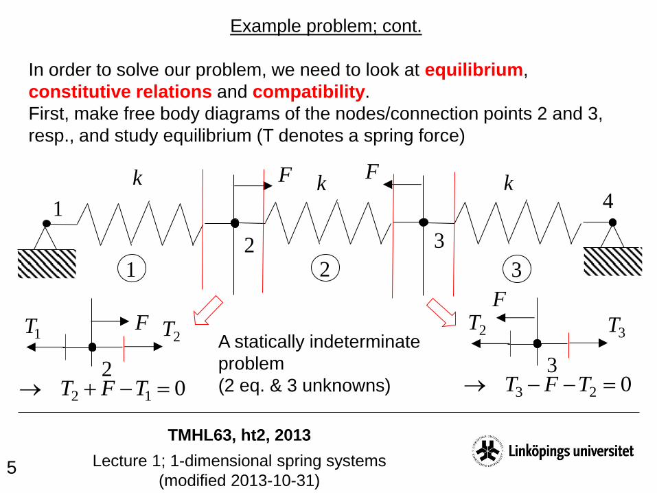
Example problem; cont.
In order to solve our problem, we need to look at equilibrium,
constitutive relations and compatibility.
First, make free body diagrams of the nodes/connection points 2 and 3,
resp., and study equilibrium (T denotes a spring force)
1
1
2 3
4
32
F Fk k k
2
F2T1T
012 TFT3
F
3T2T
023 TFT
A statically indeterminate
problem
(2 eq. & 3 unknowns)

TMHL63, ht2, 2013
Lecture 1; 1-dimensional spring systems
(modified 2013-10-31) 6
Example problem; cont.
The constitution tells us (linear springs)
1
1
2 3
4
32
F Fk k k
332211 ,, kTkTkT
where δ denotes the spring elongation. We now have 5 eq. for 6
unknowns, which we fix by compatibility
0321
Let us now do some calculations (see the next page)

TMHL63, ht2, 2013
Lecture 1; 1-dimensional spring systems
(modified 2013-10-31) 7
Example problem; cont.
1
1
2 3
4
32
F Fk k k
FTTT 231
By equilibrium
33
2312
FTT
FT
With the left expressions inserted into the right one we get
0321 TTT
By constitution and compatibility
The elongations are finally found by inserting the obtained spring forces
into the constitutive relations (only a scaling with k)

TMHL63, ht2, 2013
Lecture 1; 1-dimensional spring systems
(modified 2013-10-31) 8
Structured analysis of spring systems
Let us now focus on a general structured FE approach for spring
systems, which contains the following steps
I. Find, for each spring, a relation between the spring loading and the
spring displacements
II. Find, for the spring structure, a relation between the structural loading
and the structural displacements
III. Solve the structural problem for the given loading and restraints, and
calculate entities such as spring forces and spring elongations
Let us now see how this is done!

TMHL63, ht2, 2013
Lecture 1; 1-dimensional spring systems
(modified 2013-10-31) 9
Step I
Find, for each spring, a relation between spring loading and the
spring displacements
TMHL63, ht2, 2013
Lecture 1; 1-dimensional spring systems
(modified 2013-10-31) 10
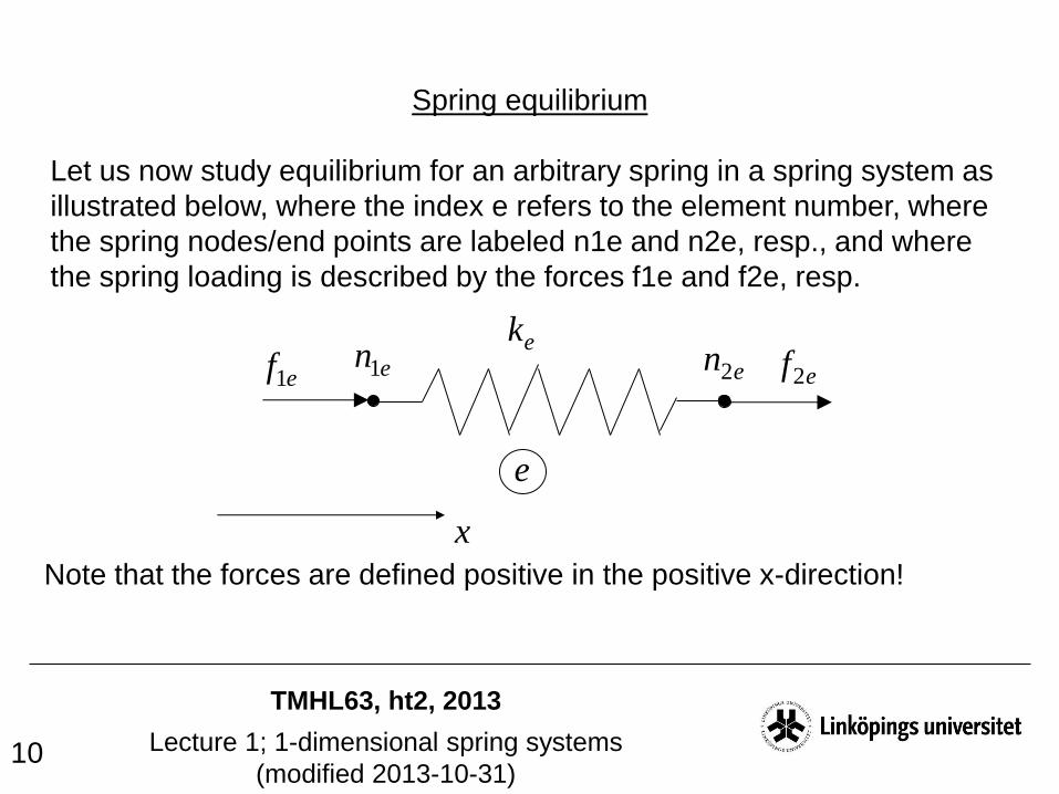
Spring equilibrium
Let us now study equilibrium for an arbitrary spring in a spring system as
illustrated below, where the index e refers to the element number, where
the spring nodes/end points are labeled n1e and n2e, resp., and where
the spring loading is described by the forces f1e and f2e, resp.
ek
e
en1 en2ef1 ef2
x
Note that the forces are defined positive in the positive x-direction!

TMHL63, ht2, 2013
Lecture 1; 1-dimensional spring systems
(modified 2013-10-31) 11
Spring equilibrium; cont.
Let us make an imaginary cut in the spring, insert the spring force Te, and
study equilibrium for each part of the spring
en1 en2ef1 ef2eT
01 ee Tf 02 ee fT
On matrix form we thus have
ee
eT
f
f
1
1
2
1

TMHL63, ht2, 2013
Lecture 1; 1-dimensional spring systems
(modified 2013-10-31) 12
Spring equilibrium; cont.
Let us now proceed and look at the spring deformation, where the
elongation (as before) is labeled δe, while the displacement of its end
nodes are called d1e and d2e; resp.
en1 en2ed1 ed2
Obviously
eee dd 12
or, on matrix form
e
ee
d
d
2
111

TMHL63, ht2, 2013
Lecture 1; 1-dimensional spring systems
(modified 2013-10-31) 13
Spring equilibrium; cont.
Since the springs are linear, we have
eee kT
TMHL63, ht2, 2013
Lecture 1; 1-dimensional spring systems
(modified 2013-10-31) 14
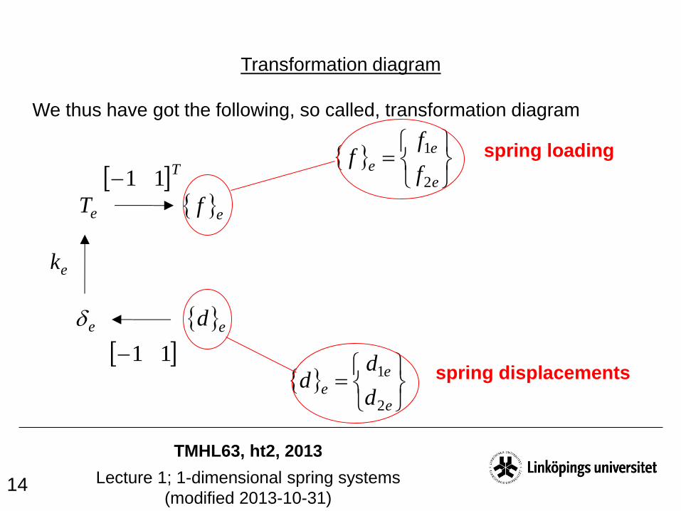
Transformation diagram
We thus have got the following, so called, transformation diagram
eT
e
ef
ed
ek
e
e
ef
ff
2
1
T11
11
e
e
ed
dd
2
1
spring loading
spring displacements

TMHL63, ht2, 2013
Lecture 1; 1-dimensional spring systems
(modified 2013-10-31) 15
Transformation diagram; cont.
A counter-clockwise trip in the transf. diag. will give us the so called
spring stiffness [k]e, which relates the spring displacements to the spring
loading
eT
e
ef
ed
ek
T11
11
eeeeee dkkTf
111
1
1
1
1
1
ek
TMHL63, ht2, 2013
Lecture 1; 1-dimensional spring systems
(modified 2013-10-31) 16
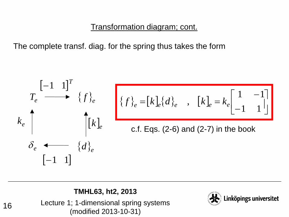
Transformation diagram; cont.
The complete transf. diag. for the spring thus takes the form
eT
e
ef
ed
ek
T11
11
ek
11
11, eeeee kkdkf
c.f. Eqs. (2-6) and (2-7) in the book

TMHL63, ht2, 2013
Lecture 1; 1-dimensional spring systems
(modified 2013-10-31) 17
Step II
Find, for the spring structure, the relation between the structual
loading and the structural displacements

TMHL63, ht2, 2013
Lecture 1; 1-dimensional spring systems
(modified 2013-10-31) 18
Structural loading and structural displacements
For the spring structure, we introduce structural nodes, with associated
structural loads and structural displacements, according to the example
below
1
1
1F
2 3
432
3F2F4F
1D4D3D
2D
TMHL63, ht2, 2013
Lecture 1; 1-dimensional spring systems
(modified 2013-10-31) 19
1
1
1F
2 3
432
3F2F4F
1D4D3D
2D
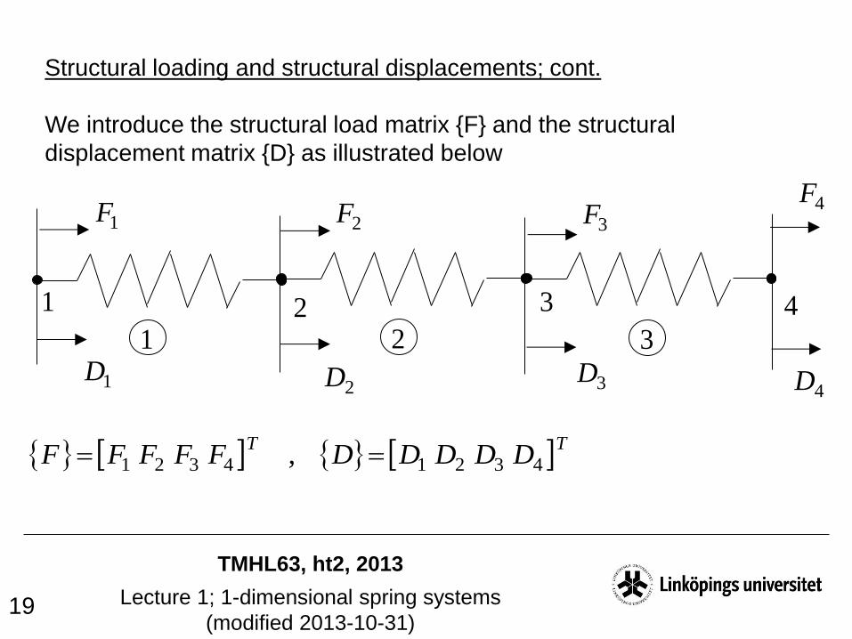
Structural loading and structural displacements; cont.
We introduce the structural load matrix {F} and the structural
displacement matrix {D} as illustrated below
TTDDDDDFFFFF 43214321 ,

TMHL63, ht2, 2013
Lecture 1; 1-dimensional spring systems
(modified 2013-10-31) 20
1
1
1F
2 3
432
3F2F4F
1D4D3D
2D
The structural problem
What we now seek is a relation between the structural load matrix {F} and
the structural displacement matrix {D}, which will take the form
DKF c.f.. Eq. (2-9) in the book
Note that we here, in contrast to the book, use small letters for spring
related quantities, and capital letters for structural quantities.

TMHL63, ht2, 2013
Lecture 1; 1-dimensional spring systems
(modified 2013-10-31) 21
The structural problem; cont.
In the transformation diagram we thus have to find
eT
e
ef
ed
ek
T11
11
ek
D
F
?
?K
?

TMHL63, ht2, 2013
Lecture 1; 1-dimensional spring systems
(modified 2013-10-31) 22
1
1
1F
2 3
432
3F2F 4F
1D4D3D
2D
The relation between spring disp. and structural disp.
We fix this by so called connectivity matrices (unique for each spring).
For spring 1 we get
11 en
11 ef
12 en
12 ef
11 ed12 ed
4
3
2
1
12
11
0010
0001
D
D
D
D
d
d
e
e
DCd 11 ][
TMHL63, ht2, 2013
Lecture 1; 1-dimensional spring systems
(modified 2013-10-31) 23
1
1
1F
2 3
432
3F2F 4F
1D4D3D
2D
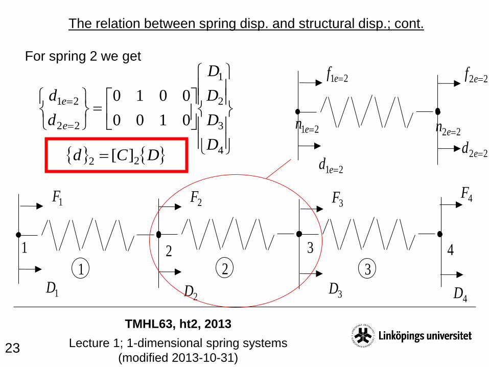
The relation between spring disp. and structural disp.; cont.
For spring 2 we get
21 en
21 ef
22 en
22 ef
21 ed22 ed
4
3
2
1
22
21
0100
0010
D
D
D
D
d
d
e
e
DCd 22 ][
TMHL63, ht2, 2013
Lecture 1; 1-dimensional spring systems
(modified 2013-10-31) 24
1
1
1F
2 3
432
3F2F 4F
1D4D3D
2D
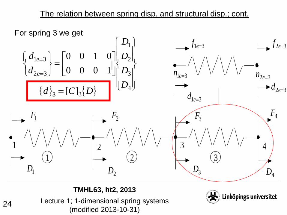
The relation between spring disp. and structural disp.; cont.
For spring 3 we get
31 en
31 ef
32 en
32 ef
31 ed32 ed
4
3
2
1
32
31
1000
0100
D
D
D
D
d
d
e
e
DCd 33 ][
TMHL63, ht2, 2013
Lecture 1; 1-dimensional spring systems
(modified 2013-10-31) 25
eT
e
ef
ed
ek
T11
11
ek
D
F
eC
?
?K
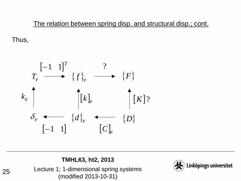
The relation between spring disp. and structural disp.; cont.
Thus,

TMHL63, ht2, 2013
Lecture 1; 1-dimensional spring systems
(modified 2013-10-31) 26
The relation between spring loads and structural loads
Let us now continue, and study the relation between spring loads and
structural loads. If looking closely at the structural nodes, and using
Newtons 3:rd law and the previously defined spring loads, we get the
following situation
1
1F
432
3F2F 4F
11 ef32 ef31 ef22 ef
21 ef12 ef1 2 3
Equilibrium implies
0111 efF
021122 ee ffF 0324 efF
031223 ee ffF
TMHL63, ht2, 2013
Lecture 1; 1-dimensional spring systems
(modified 2013-10-31) 27
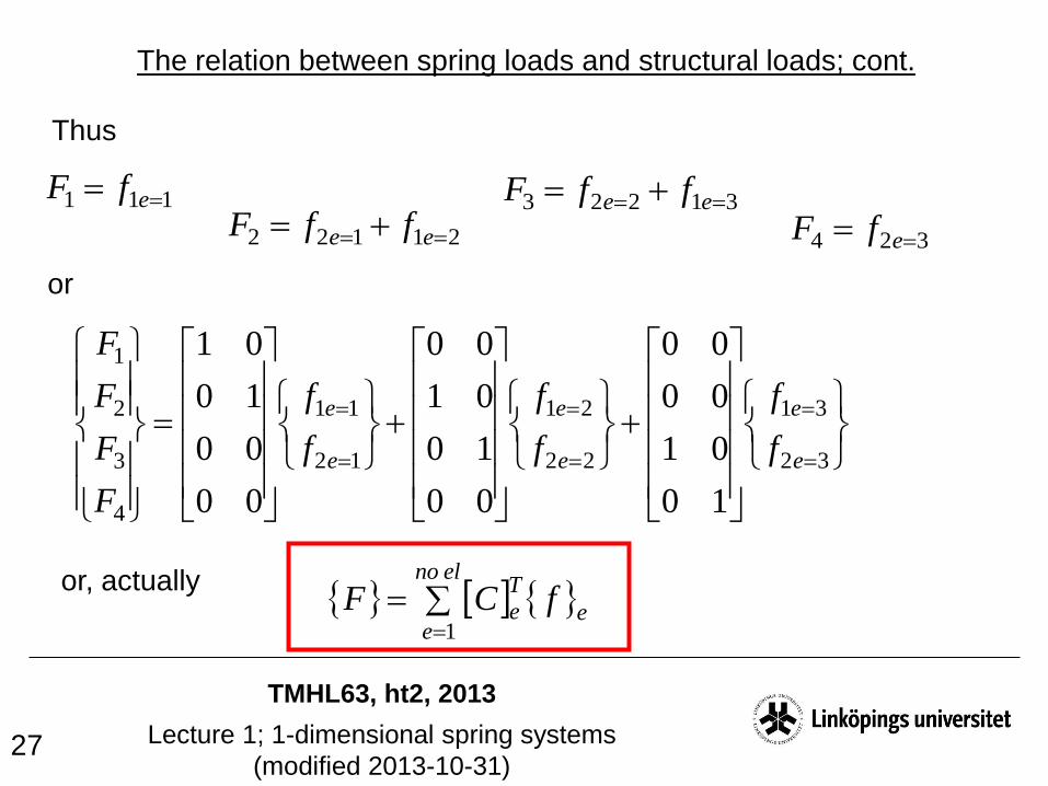
The relation between spring loads and structural loads; cont.
Thus
or
111 efF
21122 ee ffF324 efF
31223 ee ffF
32
31
22
21
12
11
4
3
2
1
10
01
00
00
00
10
01
00
00
00
10
01
e
e
e
e
e
e
f
f
f
f
f
f
F
F
F
F
or, actually
elno
ee
T
e fCF1

TMHL63, ht2, 2013
Lecture 1; 1-dimensional spring systems
(modified 2013-10-31) 28
eT
e
ef
ed
ek
T11
11
ek
D
F
eC
elno
e
T
eC1
?K
The relation between spring loads and structural loads; cont.
Thus
TMHL63, ht2, 2013
Lecture 1; 1-dimensional spring systems
(modified 2013-10-31) 29
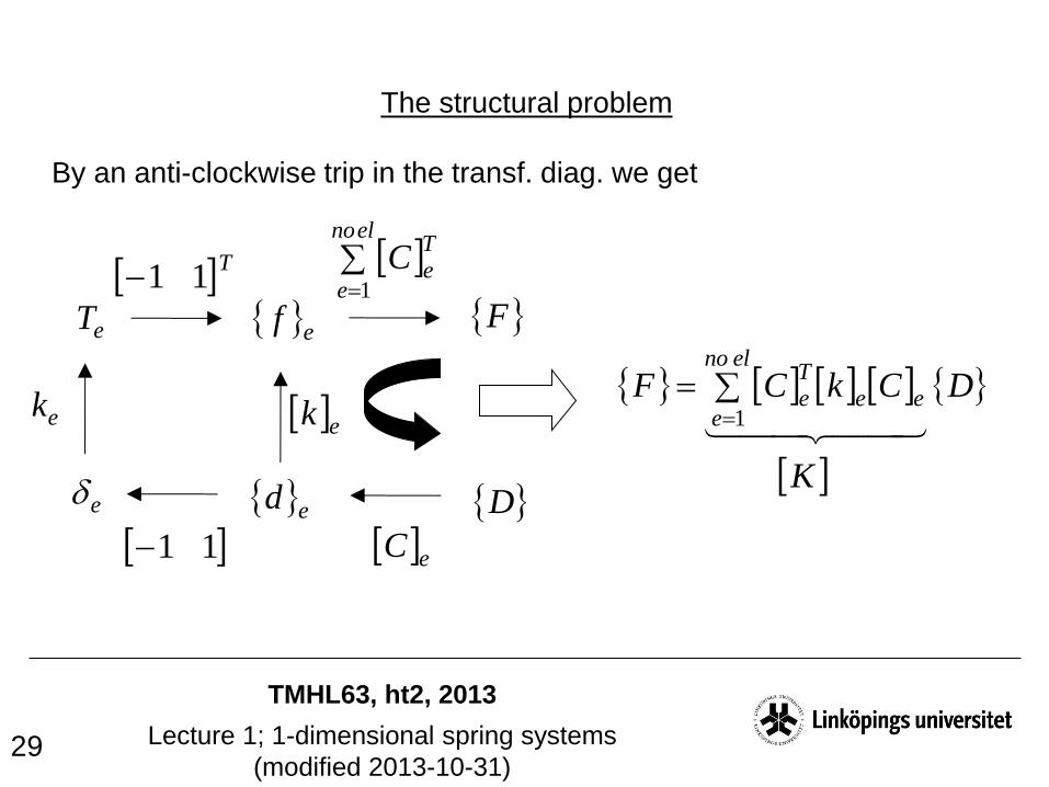
The structural problem
By an anti-clockwise trip in the transf. diag. we get
eT
e
ef
ed
ek
T11
11
ek
D
F
eC
elno
e
T
eC1
DCkCFelno
eee
T
e
1
K

TMHL63, ht2, 2013
Lecture 1; 1-dimensional spring systems
(modified 2013-10-31) 30
eT
e
ef
ed
ek
T11
11
ek
D
F
eC
elno
e
T
eC1
K
The structural problem; cont.
11
11
1
ee
elno
eee
T
e
kk
CkCK
DKF
external loads internal loads
TMHL63, ht2, 2013
Lecture 1; 1-dimensional spring systems
(modified 2013-10-31) 31
Step III
Solve the structural problem for given loading and restraints,
and calculate entities such as spring forces and
spring elongations
Let us see what this looks like in our example!

TMHL63, ht2, 2013
Lecture 1; 1-dimensional spring systems
(modified 2013-10-31) 32
Example problem
Find the spring forces and spring elongations in the example below
1
1
2 3
4
32
F
With the connectivity matrices previously found, we get
(see the next page)
Fk k k

TMHL63, ht2, 2013
Lecture 1; 1-dimensional spring systems
(modified 2013-10-31) 33
1000
0100
11
11
10
01
00
00
0100
0010
11
11
00
10
01
00
0010
0001
11
11
00
00
10
01
1
kk
kCkCKelno
eee
T
e
Example problem; cont.

TMHL63, ht2, 2013
Lecture 1; 1-dimensional spring systems
(modified 2013-10-31) 34
1100
1210
0121
0011
kK
We thus have to solve
Example problem; cont.
4
3
2
1
4
3
2
1
1100
1210
0121
0011
F
F
F
F
D
D
D
D
k= F
= 0
= 0
= - F
= ?
= ?
= ?
= ?

TMHL63, ht2, 2013
Lecture 1; 1-dimensional spring systems
(modified 2013-10-31) 35
The unknown displacements D2 and D3 are now found by solving the
equation system one gets when eliminating all rows and columns
associated with locked displacements
Example problem; cont.
4
3
2
1
4
3
2
1
1100
1210
0121
0011
F
F
F
F
D
D
D
D
k= F
= 0
= 0
= - F
= ?
= ?
= ?
= ?
implying
k
F
F
F
kD
D
F
F
D
Dk
31
1
21
12
3
1
21
12
3
2
3
2

TMHL63, ht2, 2013
Lecture 1; 1-dimensional spring systems
(modified 2013-10-31) 36
The spring elongations are then found by (c.f. the transformation
diagram)
Example problem; cont.
DC ee 11
which for instance gives
k
F
k
Fe
33
0
1
1
0
0010
0001111
Finally, the spring forces are found by (c.f. the transformation diagram)
)11( DCkkT eeeee
implying
31
FTe As before :)

TMHL63, ht2, 2013
Lecture 1; 1-dimensional spring systems
(modified 2013-10-31) 37
The way used for finding the structural problem described above
(assembling the spring stiffnesses by using connectivity matrices)
constitutes the general structured way to describe FEM.
In a hand calculation situation, it is often easier to use the procedure
described below (not using connectivity matrices), which also is the way
described in the book.
Also when considering implementation in a computer code it is
generally too expensive to work with connectivity matrices (both with
respect to computational time and memory allocation)
Example problem; cont.

TMHL63, ht2, 2013
Lecture 1; 1-dimensional spring systems
(modified 2013-10-31) 38
The contribution to [K] from element 1, which we here call [K]1, is
Example problem; cont.
11
111 kk
11 ed
11 ed
12 ed
12 ed= D1
= D1
= D2
= D2
0000
0000
0011
0011
1 kK
1D 3D4D2D
2D
3D
4D
1D
TMHL63, ht2, 2013
Lecture 1; 1-dimensional spring systems
(modified 2013-10-31) 39
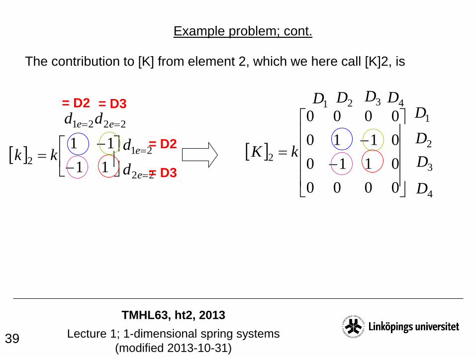
The contribution to [K] from element 2, which we here call [K]2, is
Example problem; cont.
11
112 kk
21 ed
21 ed
22 ed
22 ed= D2
= D2
= D3
= D3
0000
0110
0110
0000
2 kK
1D 3D4D2D
2D
3D
4D
1D
TMHL63, ht2, 2013
Lecture 1; 1-dimensional spring systems
(modified 2013-10-31) 40
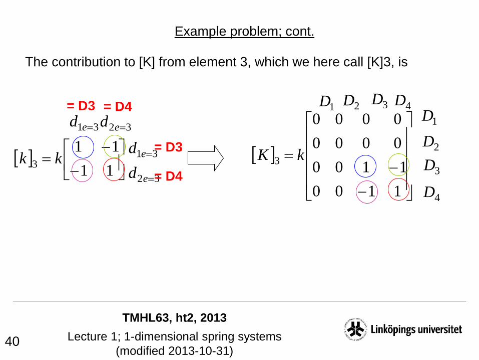
The contribution to [K] from element 3, which we here call [K]3, is
Example problem; cont.
11
113 kk
31 ed
31 ed
32 ed
32 ed= D3
= D3
= D4
= D4
1100
1100
0000
0000
3 kK
1D 3D4D2D
2D
3D
4D
1D
TMHL63, ht2, 2013
Lecture 1; 1-dimensional spring systems
(modified 2013-10-31) 41
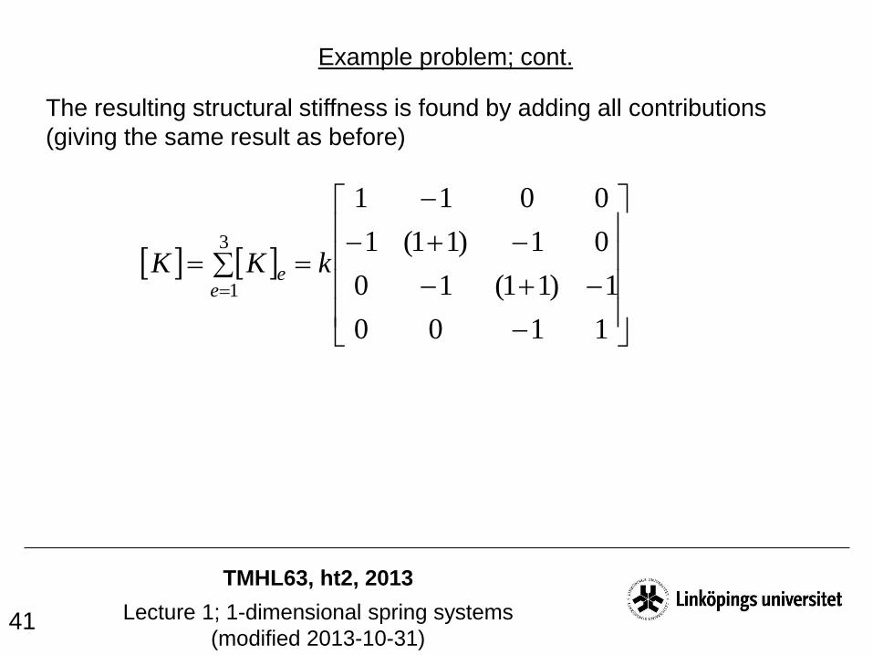
The resulting structural stiffness is found by adding all contributions
(giving the same result as before)
Example problem; cont.
1100
1)11(10
01)11(1
0011
3
1
kKKe
e

TMHL63, ht2, 2013
Lecture 1; 1-dimensional spring systems
(modified 2013-10-31) 42
An alternative treatment of our example problem by
taking advantage of the symmetry
1
1
2 3
4
32
F Fk k k
1
1
22
Fk k23
Decreasing the
length by two,
increases the
stiffness by two!
TMHL63, ht2, 2013
Lecture 1; 1-dimensional spring systems
(modified 2013-10-31) 43
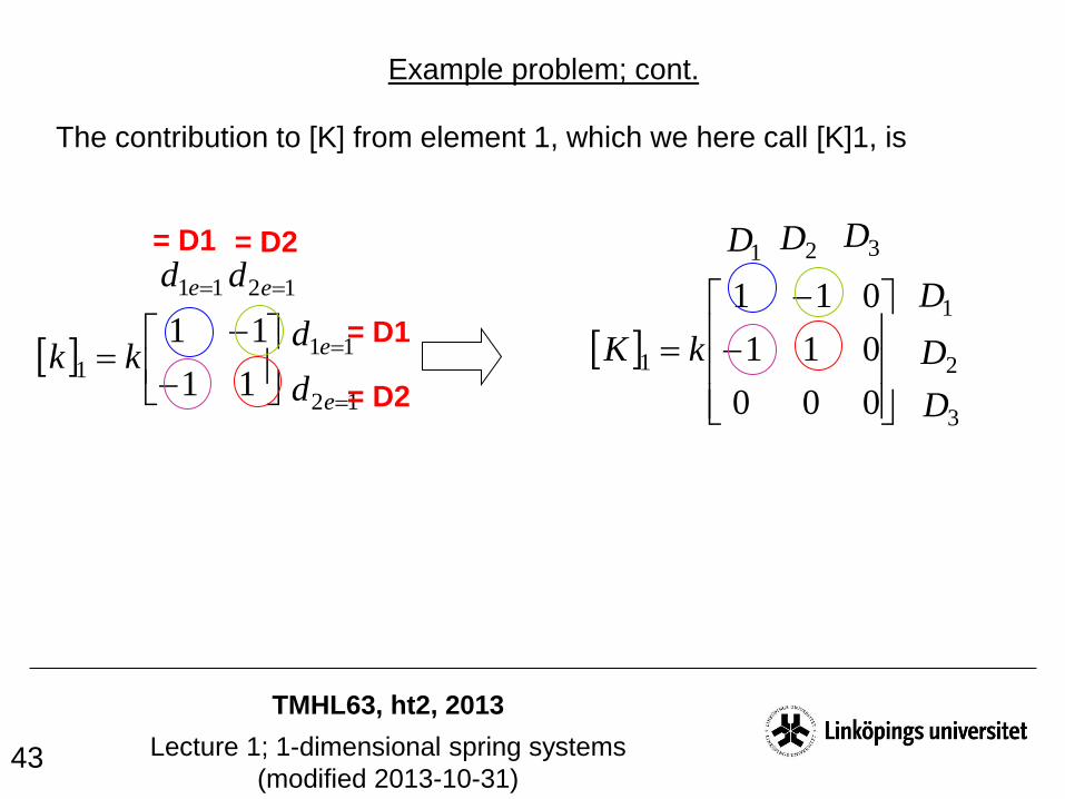
The contribution to [K] from element 1, which we here call [K]1, is
Example problem; cont.
11
111 kk
11 ed
11 ed
12 ed
12 ed= D1
= D1
= D2
= D2
000
011
011
1 kK
1D 3D2D
2D
3D
1D

TMHL63, ht2, 2013
Lecture 1; 1-dimensional spring systems
(modified 2013-10-31) 44
The contribution to [K] from element 2, which we here call [K]2, is
Example problem; cont.
11
1122 kk
21 ed
21 ed
22 ed
22 ed= D2
= D2
= D3
= D3
110
110
000
22 kK
1D 3D2D
2D
3D
1D

TMHL63, ht2, 2013
Lecture 1; 1-dimensional spring systems
(modified 2013-10-31) 45
3
2
1
3
2
1
220
231
011
F
F
F
D
D
D
k
We thus have to solve
Example problem; cont.
= F
= 0
= ?
= ?
= ?
= 0
and gets
3
2
1
3
2
1
220
231
011
F
F
F
D
D
D
k
kFD 3/2
= F
As before :)
TMHL63, ht2, 2013
Lecture 1; 1-dimensional spring systems
(modified 2013-10-31) 46
The spring stiffness matrix [k]e and the structural stiffness matrix [K] are
symmetric and singular (can not be inverted).
However, if we have prevented rigid body motions, we may solve the
structural problem (the reduced stiffness matrix obtained by removing
rows and columns associated with locked displacements is not singular).
One may finally also note that the sum of all components in a row or
column of [k]e or [K] is always zero.
Some final comments


