TML TML Pam E-1007D STRAIN GAUGES 2017 Precise & Flexible
TML TML Pam E-1007D
STRAIN GAUGES 2017Precise & Flexible
1
Approval Certificate ISO9001 Design and manufacture of strain gauges, strain measuring equipment and transducers
INTRODUCTIONThis catalog presents the full range of TML standard strain gauges and associated products
including bonding adhesives and coating materials manufactured by Tokyo Sokki Kenkyujo Co., Ltd. TML is a registered trade mark of the company.
It also describes how to find specific strain gauges, introduces typical applications, and defines the most commonly used technical terms.
CHANGES IN SPECIFICATIONSIn the interest of product improvement, the specifications in this catalog are subject to change without prior notice.
DIMENSIONSDimensions are mainly given in milimeter. Strain gauge patterns are shown in actual size, with enlargements of some miniature patterns.
PRICESPrices are not listed in this catalog. For price information or orders, please contact TML or your local representative.
HANDLING STRAIN GAUGES1. The technical data supplied herein do not reflect the
influence of the leadwire. The data must be corrected in accordance with the effect caused by the leadwire.
2. The service temperature of a strain gauge depends on the operating temperature of the adhesive, etc.
3. Insulation resistance should be checked at a voltage of less than 50V.
4. Do not apply an excessive force to the gauge leads.5. Apply adhesive to the back of the strain gauge and attach
the gauge to the specimen.6. The back of each strain gauge has been washed and
degreased. Do not contaminate it by touching it directly.7. For maintaining quality, store products in a dry place.
HANDLING BONDING ADHESIVES AND COATING MATERIALS1. Read the operation manual carefully before using bonding
adhesives and coating materials.2. After using an adhesive, wipe all remaining adhesive off the
container and nozzle with a cloth, and replace the cap.3. After using an adhesive, put the container back in the
package and store it in a cool, dark place away from fire.4. If an adhesive contacts skin or clothing, wash well with soap
and water.
Prior to using the catalog, please check the information listed below.
If you have any questions about this catalog, please contact TML or your local representative.
2
TML STRAIN GAUGES
-20°C +80°C
+80°C+10°C
Operating temperature range
Temperature compensation range
About this TML STRAIN GAUGES
Compatible adhesive & Operating temperatureCN : 0 ~ +80°CP-2 : -20 ~ +80°C
This catalog presents the full range of TML standard strain gauges and associated products including bonding adhesives and coating materials manufactured by Tokyo Sokki Kenkyujo Co., Ltd.It also describes how to find specific strain gauges, introduces typical applications, and defines the most commonly used technical terms.
Each strain gauge series includes its operating temperature and temperature compensation range along with the bar images as shown right.
Each strain gauge series is available with different bonding adhesives. Operating temperature is given along with combination of applicable adhesive, while it may differ from potential temperature of the adhesive itself.
general
Each strain gauge series is designed for object materials. 14 different materials are shown with pictograms.
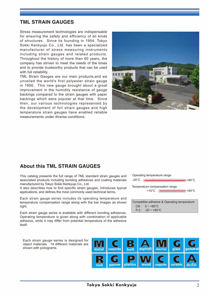
Stress measurement technologies are indispensable for ensuring the safety and efficiency of all kinds of structures. Since its founding in 1954, Tokyo Sokki Kenkyujo Co., Ltd. has been a specialized manufacturer of stress measur ing instruments inc luding st ra in gauges and re lated products. Throughout the history of more than 60 years, the company has striven to meet the needs of the times and to provide trustworthy products that can be used with full reliability.TML Strain Gauges are our main products,and we unveiled the world's first polyester strain gauge in 1956. This new gauge brought about a great improvement in the humidity resistance of gauge backings compared to the strain gauges with paper backings which were popular at that time. Since then, our var ious technologies represented by the development of foi l strain gauges and high temperature strain gauges have enabled reliable measurements under diverse conditions.
auto
3
Developing Strain Gauges and Instruments
Testing and Inspection Standards
TML STRAIN GAUGE TESTING AND INSPECTION STANDARDS
¶ ASTM E251-74"Standard Test Methods for Performance Characteristics of Metallic Bonded Resistance Strain Gauges"Designation: E251-92, ASTM
¶ BSI BS6888"Methods for Calibration of Bonded Electric Resistance Strain Gauges"Draft for development 6:1972. BSI
¶ NAS942"Strain Gauges, Bonded Resistance"Classification Specification NAS 942, 1963
¶ VDE/VDI Richtlinen NR 2635"Bonded Electric Resistance Strain Gauges with Metallic Measurement Grids - Characteristics and Testing Conditions"VDE/VDI-Richtlinen NR 2635 August, 1974
¶ Other standardsJIS Z2300-91 - "Glossary of Terms Used in Nondestructive Testing", Japan Industrial StandardNDIS 4001:2008 - "Glossary of Terms Relating to Electric Resistance Strain Gauges", NDI, Japan
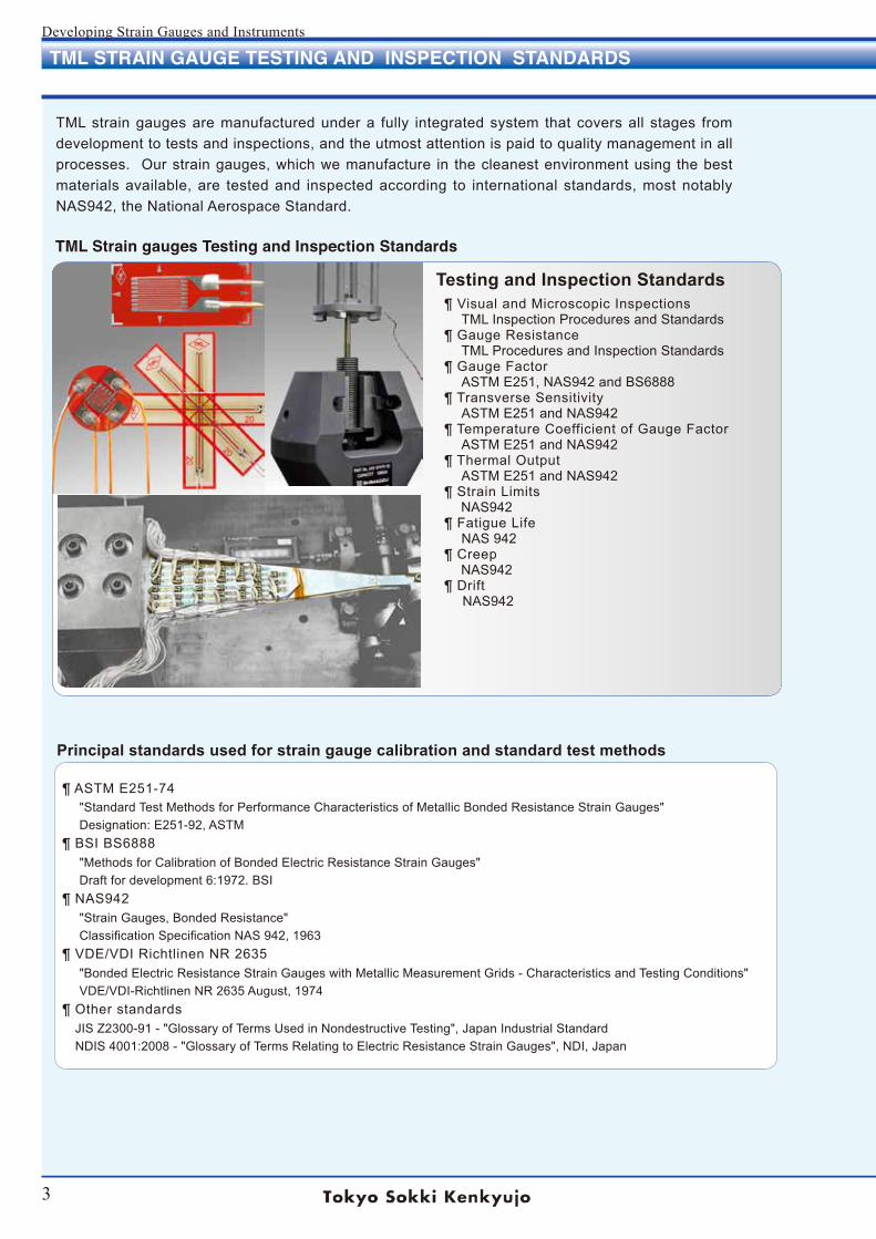
TML Strain gauges Testing and Inspection Standards
Principal standards used for strain gauge calibration and standard test methods
TML strain gauges are manufactured under a fully integrated system that covers all stages from development to tests and inspections, and the utmost attention is paid to quality management in all processes. Our strain gauges, which we manufacture in the cleanest environment using the best materials available, are tested and inspected according to international standards, most notably NAS942, the National Aerospace Standard.
¶ Visual and Microscopic InspectionsTML Inspection Procedures and Standards
¶ Gauge ResistanceTML Procedures and Inspection Standards
¶ Gauge FactorASTM E251, NAS942 and BS6888
¶ Transverse SensitivityASTM E251 and NAS942
¶ Temperature Coefficient of Gauge FactorASTM E251 and NAS942
¶ Thermal OutputASTM E251 and NAS942
¶ Strain Limits NAS942
¶ Fatigue LifeNAS 942
¶ Creep NAS942
¶ Drift NAS942
4
Developing Strain Gauges and Instruments
TABLE OF CONTENTS
TML Strain Gauge Applications ……………………………………………………………………………………5General Description ………………………………………………………………………………………………7Technical Terms ……………………………………………………………………………………………………9Strain Gauge Measurement ………………………………………………………………………………… 11Measuring method of strain and temperature ………………………………………………………………… 15TML Foil Strain Gauges F series GOBLET compliant to CE marking ……………………………………… 16Strain Gauge Bridge Circuit …………………………………………………………………………………… 17TML Strain Gauge Coding System/ Package Designation ………………………………………………… 21TML Strain Gauge Selection …………………………………………………………………………………… 25Primary Installation Bonding/Overcoating …………………………………………………………………… 31Strain Gauge Extension Leadwires …………………………………………………………………………… 33How are integral leadwires jointed……………………………………………………………………………… 35Strain Gauge Installation ……………………………………………………………………………………… 39Strain Gauge Tool Kit …………………………………………………………………………………………… 40Strain Gauge Users' Guide / Strain Gauge Performance Characteristics ………………………………… 40Combination use of strain gauges and dedicated leadwires ………………………………………………… 41General use strain gauges F series …………………………………………………………………………… 43General use strain gauges F series GOBLET compliant to CE marking ………………………………… 48Waterproof strain gauges WF series ………………………………………………………………………… 52High temperature strain gauges QF series …………………………………………………………………… 53High temperature strain gauges ZF series …………………………………………………………………… 55High temperature strain gauges EF series ………………………………………………………………… 56High and Low temperature strain gauges CEF series ……………………………………………………… 56Cryogenic temperature strain gauges CF series……………………………………………………………… 57Weldable strain gauges AW series …………………………………………………………………………… 59Spot Welder W-50RB ………………………………………………………………………………………… 64Concrete material use Bondable type P series, PF series ………………………………………………………………………… 65 Bondable type FLM/WFLM series, Embedment type PM series ……………………………………… 66 Embedment type PMF series ……………………………………………………………………………… 68Asphalt Pavement use Embedment type PMFLS series …………………………………………………………………………… 68 Concrete material use/Civil Engineering Strain Transducer KM series ……………………………………………………………………………… 69Asphalt pavement use/Civil Engineering Strain Transducer KM-HAS series ………………………………………………………………………… 70Composite materials use UBF series, BF series……………………………………………………………… 71Low elastic modulus materials use GF series ……………………………………………………………… 72Wood materials LF series, PFLW / PLW series ……………………………………………………………… 73Magnetic field strain gauges MF series ……………………………………………………………………… 74Post-Yield Strain gauges YEF series, YF series, YHF series ……………………………………………… 75High endurance Strain Gauges DSF series, One-side Strain Gauges DD series ……………………… 78Crack Detection Gauges FAC series, Stress Gauges SF series …………………………………………… 79Temperature Gauges TF series, Platinum RTD/ Thermocouple …………………………………………… 80Transducer-specific Strain Gauges …………………………………………………………………………… 81Bolt Strain Gauges BTM series, BTMC series ……………………………………………………………… 83Connecting Terminals …………………………………………………………………………………………… 85Strain Gauge Clamp Gauge Mate / Pressee ………………………………………………………………… 86Strain Gauge Adhesives ……………………………………………………………………………………… 87Coating Materials ……………………………………………………………………………………………… 89Gauge Protector, Coating Tape ………………………………………………………………………………… 91Frictional Axial Strain Transducer FGAH-1B series ………………………………………………………… 92Frictional Torque Sensor System FGDH series ……………………………………………………………… 93Frictional Strain Checker FGMH series ……………………………………………………………………… 95TML Strain Measuring Instruments …………………………………………………………………………… 97
Table of contents
5
Developing Strain Gauges and Instruments
TML STRAIN GAUGE APPLICATIONS
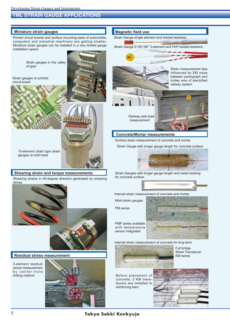
Miniature strain gauges
Shearing strain and torque measurements
Printed circuit boards and surface mounting parts of automobile, computers and industrial machinery are getting smaller. Miniature strain gauges can be installed in a very limited gauge installation space.
Shearing strains in 45-degree direction generated by shearing stress.
Strain gauges in the valley of gear
Strain gauges on printedcircuit board
10-element chain type strain gauges on bolt head
3-element residual stress measurement b y c e n t e r - h o l e drilling method
Internal strain measurement of concrete and mortar
Internal strain measurement of concrete for long term
Mold strain gauges
PM series
PMF series available wi th temperature sensor integrated
Full bridgeStrain TransducerKM series
Before p lacement of concrete, 3 KM trans-ducers are installed to reinforcing bars.
Concrete/Mortar measurementsSurface strain measurement of concrete and mortar
Strain Gauge with longer gauge length for concrete surface
Magnetic field use
Residual stress measurement
Strain Gauge single element and twisted leadwire
Strain Gauge 0°/45°/90° 3-element and FEP twisted leadwire
Strain measurement less influenced by EM noise between pantograph and trolley wire of electrified railway system
Strain Gauges with longer gauge length and metal backingfor concrete surface
Railway axle load measurement
6
Developing Strain Gauges and Instruments
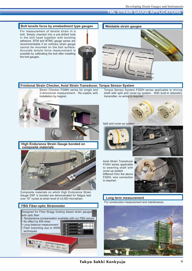
Bolt tensile force by emebedment type gauges
Frictional Strain Checker, Axial Strain Transducer, Torque Sensor System
Long term measurement
Weldable strain gaugesFor measurement of tensile strain in a bolt. Simply inserted into a pre-drilled hole in the bolt head together with bonding adhesive. BTM and BTMC gauge series are recommendable if an ordinary strain gauge cannot be mounted on the bolt surface. Accurate tensile force measurement is possible by calibrating the bolt after installing the bolt gauges.
High Endurance Strain Gauge bonded on composite materials
Composite materials on which High Endurance Strain Gauge DSF is bonded are demonstrated for fatigue test over 107 cycles at strain level of ±3,000 microstrain.
For construction measurement and maintenance.
TML STRAIN GAUGE APPLICATIONS
FBG Fiber-optic Strainmeter
Strain Checker FGMH series for single and 3-directional measurement. Re-usable with installation by magnet.
Torque Sensor System FGDH series applicable to driving shaft with split and cover-up system. With built-in telemetry transmitter, no wiring is required.
Split and cover-up system
Axial Strain Transducer FGAH series applicable to steerling shaft with cover-up systemDifferent from the above FGDH, wire connection is required.
• No effect by EM noise• Long distance measurement• Fiber branching due to WDM
techniques
Designed for Fiber Bragg Grating based strain gauges with optic fiber• Temperature-compensation available with our FBG sensor
7
Developing Strain Gauges and Instruments
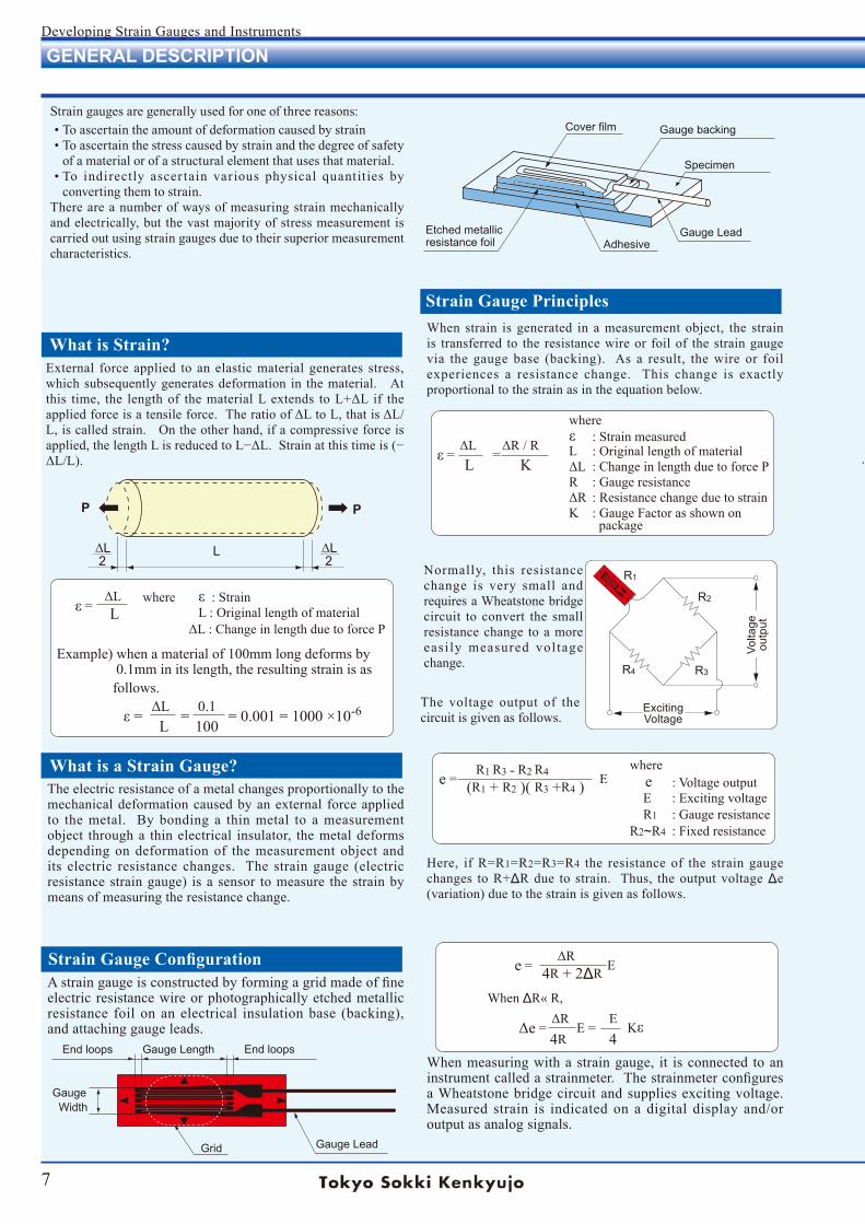
Strain gauges are generally used for one of three reasons:• To ascertain the amount of deformation caused by strain• To ascertain the stress caused by strain and the degree of safety
of a material or of a structural element that uses that material.• To indirectly ascer tain various physical quantit ies by
converting them to strain.There are a number of ways of measuring strain mechanically and electrically, but the vast majority of stress measurement is carried out using strain gauges due to their superior measurement characteristics.
P P
ΔL 2
ΔL 2
L
Volta
geou
tput
where ε : Strain measuredL : Original length of materialΔL :ChangeinlengthduetoforcePR : Gauge resistanceΔR :ResistancechangeduetostrainK : Gauge Factor as shown on package
ΔLΔR/Rε = = L K
R1
R2
R3R4
ExcitingVoltage
where ε : Strain L : Original length of materialΔL:ChangeinlengthduetoforceP
ΔLε = L
R1 R3˗R2 R4e = E (R1 + R2 )( R3 +R4 )where e : Voltage output E : Exciting voltage R1 : Gauge resistanceR2~R4 : Fixed resistance
ΔR e = E 4R + 2ΔR
When ΔR« R,ΔR Δe = E =
E Kε
4R 4
Example) when a material of 100mm long deforms by 0.1mm in its length, the resulting strain is as follows. ΔL0.1 ε= ==0.001=1000×10-6 L 100
End loops End loopsGauge Length
Gauge LeadGrid
Gauge Width
Cover film Gauge backing
Specimen
Gauge LeadAdhesive
Etched metallicresistance foil
Astraingaugeisconstructedbyformingagridmadeoffineelectric resistance wire or photographically etched metallic resistance foil on an electrical insulation base (backing), and attaching gauge leads.
Strain Gauge Configuration
Normally, this resistance change is very small and requires a Wheatstone bridge circuit to convert the small resistance change to a more easi ly measured voltage change.
What is a Strain Gauge?
When strain is generated in a measurement object, the strain is transferred to the resistance wire or foil of the strain gauge via the gauge base (backing). As a result, the wire or foil experiences a resistance change. This change is exactly proportional to the strain as in the equation below.
Strain Gauge Principles
The electric resistance of a metal changes proportionally to the mechanical deformation caused by an external force applied to the metal. By bonding a thin metal to a measurement object through a thin electrical insulator, the metal deforms depending on deformation of the measurement object and its electric resistance changes. The strain gauge (electric resistance strain gauge) is a sensor to measure the strain by means of measuring the resistance change.
GENERAL DESCRIPTION
External force applied to an elastic material generates stress, which subsequently generates deformation in the material. At this time, the lengthof thematerialLextends toL+ΔL if theappliedforceisatensileforce.TheratioofΔLtoL,thatisΔL/L, is called strain. On the other hand, if a compressive force is applied,thelengthLisreducedtoL−ΔL.Strainatthistimeis(−ΔL/L).
What is Strain?
The voltage output of the circuit is given as follows.
Here, if R=R1=R2=R3=R4 the resistance of the strain gauge changes to R+ΔR due to strain. Thus, the output voltage Δe (variation) due to the strain is given as follows.
When measuring with a strain gauge, it is connected to an instrumentcalledastrainmeter.Thestrainmeterconfiguresa Wheatstone bridge circuit and supplies exciting voltage. Measured strain is indicatedon adigital display and/oroutput as analog signals.
8
Developing Strain Gauges and Instruments
Measurement of principal strain and stress using 3-element rectangular rosette gauge
σε x = E νσεy = νεx = E
where σ : StressE : Elastic modulusεx : Strain in x directionεy : Strain in y directionν :Poisson'sratio
εx = εx' νεy' σx νσy = E E 1 =(σx νσy) E
εy = εy' νεx' σy νσx = E E 1 =(σy νσx) E
εy' : strain in the y direction due to σy
εx' : strain in the x direction due to σx
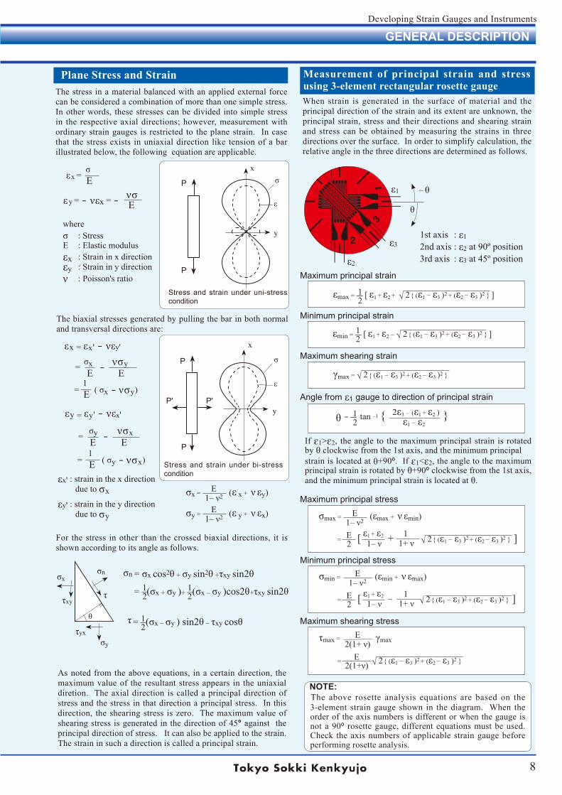
Plane Stress and StrainThe stress in a material balanced with an applied external force can be considered a combination of more than one simple stress. In other words, these stresses can be divided into simple stress in the respective axial directions; however, measurement with ordinary strain gauges is restricted to the plane strain. In case that the stress exists in uniaxial direction like tension of a bar illustrated below, the following equation are applicable.
Stress and strain under uni-stress condition
P
P
x
y
σ
ε
P
P' P'
P
x
y
σ
ε
Stress and strain under bi-stress condition
The biaxial stresses generated by pulling the bar in both normal and transversal directions are:
As noted from the above equations, in a certain direction, the maximum value of the resultant stress appears in the uniaxial diretion. The axial direction is called a principal direction of stress and the stress in that direction a principal stress. In this direction, the shearing stress is zero. The maximum value of shearing stress is generated in the direction of 45° against the principal direction of stress. It can also be applied to the strain. The strain in such a direction is called a principal strain.
When strain is generated in the surface of material and the principal direction of the strain and its extent are unknown, the principal strain, stress and their directions and shearing strain and stress can be obtained by measuring the strains in three directions over the surface. In order to simplify calculation, the relative angle in the three directions are determined as follows.
1st axis : ε12nd axis : ε2 at 90º position3rd axis : ε3 at 45º position
Maximum principal strain
Minimum principal strain
Maximum shearing strain
Angle from ε1 gauge to direction of principal strain
εmax=―[ ε1 + ε2 + √ 2 (ε1 −ε3 )2 + (ε2 −ε3 )2 ]
εmin=―[ ε1 + ε2 – √ 2 (ε1 −ε3 )2 + (ε2 −ε3 )2 ]
12
12
γmax = √ 2 (ε1 −ε3 )2 + (ε2 −ε3 )2
12θ=―tan –1 2ε3 – (ε1 + ε2 )
ε1 −ε2
If ɛ1>ɛ2, the angle to the maximum principal strain is rotated by θ clockwise from the 1st axis, and the minimum principalstrain is located at θ+90º. If ɛ1<ɛ2, the angle to the maximum principal strain is rotated by θ+90º clockwise from the 1st axis, and the minimum principal strain is located at θ.
Maximum principal stress
Minimum principal stress
Maximum shearing stress
σmax = (εmax + ν εmin)E1–ν2
E2 = [ + √ 2 (ε1 −ε3 )2 + (ε2 −ε3 )2 ]ε1 + ε2
1–ν 1 1+ν
σmin = (εmin + ν εmax)E1–ν2
E2 = [ – √ 2 (ε1 −ε3 )2 + (ε2 −ε3 )2 ]ε1 + ε2
1–ν 1 1+ν
τmax = γmaxE
2(1+ν)E
2(1+ν) = √ 2 (ε1 −ε3 )2 + (ε2 −ε3 )2
ε1
ε2
ε3
θ
– θ
NOTE: The above rosette analysis equations are based on the 3-element strain gauge shown in the diagram. When the order of the axis numbers is different or when the gauge is not a 90º rosette gauge, different equations must be used. Check theaxisnumbersofapplicablestraingaugebeforeperforming rosette analysis.
σx = (ε x + ν εy)E1–ν2
σy = (ε y + ν εx)E1–ν2
For the stress in other than the crossed biaxial directions, it is shown according to its angle as follows.
σnσx
σy
τ
τyx
τxy
σn =σx cos2θ + σy sin2θ +τxy sin2θ
= –(σx + σy )+ –(σx – σy )cos2θ+τxy sin2θ12
12
= –(σx – σy )sin2θ – τxy cosθ12
τθ
GENERAL DESCRIPTION
9
Developing Strain Gauges and Instruments
TECHNICAL TERMS
This dimension represents the actual grid length in the sensitive direction.
Gauge Length
Gauge ResistanceThe gauge resistance is the electrical resistance of an unbonded gauge at room temperature and subject to no externalstress.Thegaugeresistancegenerallyusedis120Ωbutgaugesarealsoproducedwithgaugeresistanceof60Ω,350Ωand1000Ω. High-resistancegaugesyield ahighbridge output when high voltages are applied but they are also susceptible to noise. The majority of the strain gauges used in the production of transducers have a gauge resistance of350Ω.
Gauge Factor
The amount shown in the following equation is called the gauge factor. In this equation, ε indicates the strain generated due to uniaxial stress in the direction of the strain gauge axis. ΔR/Rshowstheratioofresistancechangedueto strain ε.
where K : Gauge Factor ε : Mechanical strain R : Gauge ResistanceΔR:Resistancechange
ΔR/RK = ε
Longitudinal sensitivity is very similar to the gauge factor and refers to the sensitivity of the gauge when no strain is applied in the direction perpendicular to the gauge axis.
Longitudinal Sensitivity
The gauge also exhibits sensitivity in the direction per-pendicular to the axial direction. The amount shown in the following equation due to the uniaxial strain (εt) in the direction perpendicular to the gauge axis, and the resistance variation generated thereby, is called transverse sensitivity (Kt).
Transverse Sensitivity
where Kt : Transverse Sensitivity ε t : Uniaxial strain perpendicu- lar to the gauge axis
ΔR/RKt= ×100 ε t
This refers to the ratio of transverse sensitivity to longitudinal sensitivity. This is usually 1% or less and does not usually pose a problem except in high-precision measurement or in locations with biaxial strain.
Transverse Sensitivity Ratio
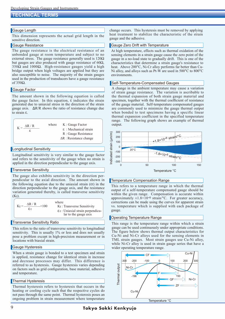
This refers to a temperature range in which the thermal output of a self-temperature compensated gauge should be within thegivenrange. Compensation isaccuratewithinapproximately±1.8×10⁻⁶ strain/°C. Forgreateraccuracy,corrections can be made using the curves for apparent strain vs. temperature which is supplied with each package of gauge.
Temperature Compensation Range
Thermal hysteresis refers to hysteresis that occurs in the heating or cooling cycle such that the respective cycles do not pass through the same point. Thermal hysteresis poses an ongoing problem in strain measurement where temperature
Thermal Hysteresis
When a strain gauge is bonded to a test specimen and strain is applied, resistance change for identical strain in increase and decrease processes may differ. This difference is referred to as hysteresis. Gauge hysteresis varies depending onfactorssuchasgridconfiguration,basematerial,adhesiveand temperature.
Gauge Hysteresis
This range is the temperature range within which a strain gauge can be used continuously under appropriate conditions. The figure below shows thermal output characteristics for Cu-NiandNi-Cralloysused for thesensingelements inTMLstraingauges. Most straingaugesuseCu-Nialloy,whileNi-Cralloyisusedinstraingaugeseriesthathaveawider operating temperature range.
Operating Temperature Range
Temperature °C
Ther
mal
out
put
At high temperature, effects such as thermal oxidation of the sensing elements in a strain gauge cause the zero point of the gauge in a no-load state to gradually drift. This is one of the characteristics thatdetermineastraingauge'sresistancetoheat. Above 200°C,Ni-CralloyperformsfarbetterthanCu-Nialloy,andalloyssuchasPt-Wareusedin500°Cto800°Cenvironments.
Gauge Zero Drift with Temperature
A change in the ambient temperature may cause a variation of strain gauge resistance. The variation is ascribable to the thermal expansion of both strain gauge material and specimen,togetherwiththethermalcoefficientofresistanceof the gauge material. Self-temperature compensated gauges are commonly used to minimize the gauge thermal output when bonded to test specimens having a specific linear thermal expansion coefficient in the specified temperature range. The following graph shows an example of thermal output.
Self-Temperature-Compensated Gauges
change occurs. This hysteresis must be removed by applying heat treatment to stabilize the characteristic of the strain gauge and the adhesive.
F
QF
ZF
CF Cu-Ni
Cu-Ni
Ni-Cr
Ni-Cr
-300 -200 -100 0 100 200 300
-196 150
20°C
300
200
100
0
-100
-200
-3000 50 100 150
+1.8×10⁻⁶ strain/°C
-1.8×10⁻⁶ strain/°C
Temperature °C
Indi
cate
d st
rain
(µm
/m)
10
Developing Strain Gauges and Instruments
TECHNICAL TERMS
The frequency response of a strain gauge is determined by the gauge length and the longitudinal elastic wave speed of the test specimen. Frequency response limits are typically only a concern under impact conditions.
Strain Gauge Frequency Response
Different gauge lengths should be selected depending on specimens. Gauges with short gauge lengths are used to measure local strain, while gauges with long lengths can be used to measure averaged strain over a larger area. For a heterogenous material, a gauge length is required that can average out irregular strain in the material. For example, as concrete is composed of cement and aggregate (gravel or sand, etc.) the length of a gauge used is more than three times the diameter of the aggregate so as to give an averaged evaluation of the concrete.
Gauge Length Selection
Fatigue Life
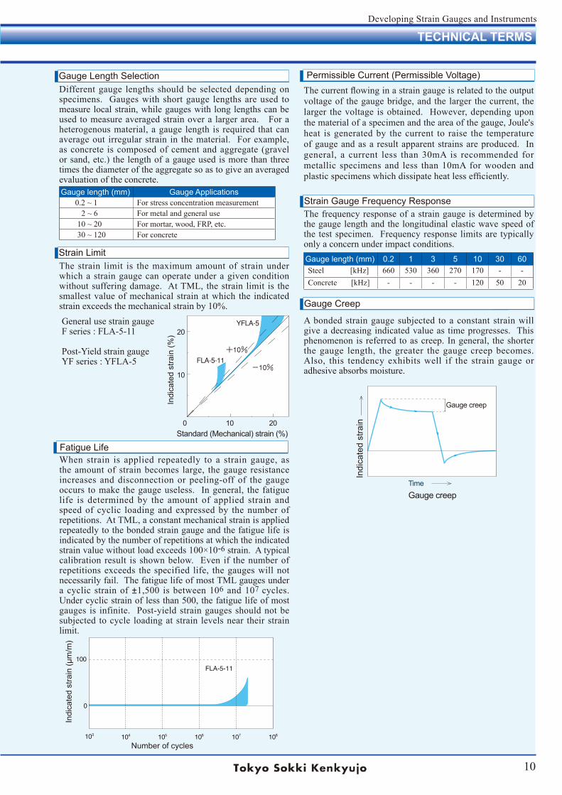
The strain limit is the maximum amount of strain under which a strain gauge can operate under a given condition without suffering damage. At TML, the strain limit is the smallest value of mechanical strain at which the indicated strain exceeds the mechanical strain by 10%.
Strain Limit
Thecurrentflowinginastraingaugeisrelatedtotheoutputvoltage of the gauge bridge, and the larger the current, the larger the voltage is obtained. However, depending upon thematerialofaspecimenandtheareaofthegauge,Joule'sheat is generated by the current to raise the temperature of gauge and as a result apparent strains are produced. In general, a current less than 30mA is recommended for metallic specimens and less than 10mA for wooden and plasticspecimenswhichdissipateheatlessefficiently.
Permissible Current (Permissible Voltage)
Gauge length (mm) 0.2 1 3 5 10 30 60Steel [kHz] 660 530 360 270 170 - -Concrete[kHz] - - - - 120 50 20
Gauge length (mm) Gauge Applications0.2 ~ 1 For stress concentration measurement
2 ~ 6 For metal and general use10 ~ 20 Formortar,wood,FRP,etc.30 ~ 120 For concrete
0 10 20
20
10
Indi
cate
d st
rain
(%)
Standard (Mechanical) strain (%)
General use strain gaugeF series : FLA-5-11
Post-YieldstraingaugeYFseries:YFLA-5
Indi
cate
d st
rain
(µm
/m)
Number of cycles
A bonded strain gauge subjected to a constant strain will give a decreasing indicated value as time progresses. This phenomenon is referred to as creep. In general, the shorter the gauge length, the greater the gauge creep becomes. Also, this tendency exhibits well if the strain gauge or adhesive absorbs moisture.
Gauge Creep
Indi
cate
d st
rain
Gauge creep
Gauge creep
Time
When strain is applied repeatedly to a strain gauge, as the amount of strain becomes large, the gauge resistance increases and disconnection or peeling-off of the gauge occurs to make the gauge useless. In general, the fatigue life is determined by the amount of applied strain and speed of cyclic loading and expressed by the number of repetitions. At TML, a constant mechanical strain is applied repeatedly to the bonded strain gauge and the fatigue life is indicated by the number of repetitions at which the indicated strainvaluewithoutloadexceeds100×10-6 strain. A typical calibration result is shown below. Even if the number of repetitions exceeds the specified life, the gauges will not necessarily fail. The fatigue life of most TML gauges under a cyclic strain of ±1,500 is between 106 and 107 cycles. Under cyclic strain of less than 500, the fatigue life of most gauges is infinite. Post-yieldstraingaugesshouldnotbesubjected to cycle loading at strain levels near their strain limit.
11
Developing Strain Gauges and Instruments
STRAIN GAUGE MEASUREMENT
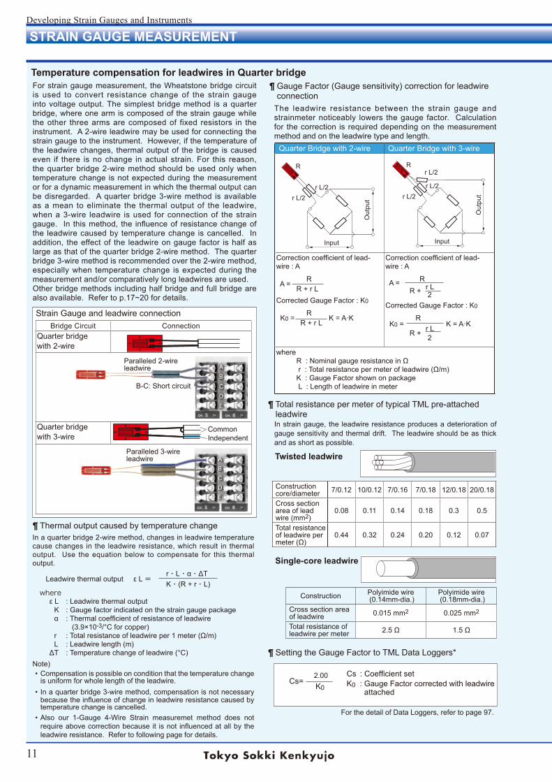
Temperature compensation for leadwires in Quarter bridgeFor strain gauge measurement, the Wheatstone bridge circuit is used to convert resistance change of the strain gauge into voltage output. The simplest bridge method is a quarter bridge, where one arm is composed of the strain gauge while the other three arms are composed of fixed resistors in the instrument. A 2-wire leadwire may be used for connecting the strain gauge to the instrument. However, if the temperature of the leadwire changes, thermal output of the bridge is caused even if there is no change in actual strain. For this reason, the quarter bridge 2-wire method should be used only when temperature change is not expected during the measurement or for a dynamic measurement in which the thermal output can be disregarded. A quarter bridge 3-wire method is available as a mean to eliminate the thermal output of the leadwire, when a 3-wire leadwire is used for connection of the strain gauge. In this method, the influence of resistance change of the leadwire caused by temperature change is cancelled. In addition, the effect of the leadwire on gauge factor is half as large as that of the quarter bridge 2-wire method. The quarter bridge 3-wire method is recommended over the 2-wire method, especially when temperature change is expected during the measurement and/or comparatively long leadwires are used.Other bridge methods including half bridge and full bridge are also available. Refer to p.17~20 for details.
Bridge Circuit ConnectionQuarter bridgewith 2-wire
Quarter bridgewith 3-wire
Strain Gauge and leadwire connection
Paralleled 2-wireleadwire
B-C: Short circuit
Paralleled 3-wireleadwire
¶ Thermal output caused by temperature changeIn a quarter bridge 2-wire method, changes in leadwire temperature cause changes in the leadwire resistance, which result in thermal output. Use the equation below to compensate for this thermal output. r・L・α・ΔT Leadwire thermal output ε L= K・(R + r・L) where ε L : Leadwire thermal output K : Gauge factor indicated on the strain gauge package α : Thermal coefficient of resistance of leadwire (3.9×10⁻³/°C for copper) r : Total resistance of leadwire per 1 meter (Ω/m) L : Leadwire length (m) ΔT : Temperature change of leadwire (°C)Note) • Compensation is possible on condition that the temperature change
is uniform for whole length of the leadwire.• In a quarter bridge 3-wire method, compensation is not necessary
because the influence of change in leadwire resistance caused by temperature change is cancelled.
• Also our 1-Gauge 4-Wire Strain measuremet method does not require above correction because it is not influenced at all by the leadwire resistance. Refer to following page for details.
¶ Gauge Factor (Gauge sensitivity) correction for leadwire connection
The leadwire resistance between the strain gauge and strainmeter noticeably lowers the gauge factor. Calculation for the correction is required depending on the measurement method and on the leadwire type and length.
Quarter Bridge with 2-wire Quarter Bridge with 3-wire
Correction coefficient of lead-wire : A
R A = R + r LCorrected Gauge Factor : K0
R K0 = K = A·K R + r L
Correction coefficient of lead-wire : A
R A = r L R + 2Corrected Gauge Factor : K0
R K0 = K = A·K r L R + 2
where R : Nominal gauge resistance in Ω r : Total resistance per meter of leadwire (Ω/m) K : Gauge Factor shown on package L : Length of leadwire in meter
Rr L/2
r L/2r L/2
Input
Out
put
R
r L/2r L/2
Input
Out
put
¶ Total resistance per meter of typical TML pre-attached leadwire
In strain gauge, the leadwire resistance produces a deterioration of gauge sensitivity and thermal drift. The leadwire should be as thick and as short as possible.
Twisted leadwire
Construction core/diameter 7/0.12 10/0.12 7/0.16 7/0.18 12/0.18 20/0.18
Cross section area of lead wire (mm2)
0.08 0.11 0.14 0.18 0.3 0.5
Total resistance of leadwire per meter (Ω)
0.44 0.32 0.24 0.20 0.12 0.07
Single-core leadwire
Construction Polyimide wire (0.14mm-dia.)
Polyimide wire (0.18mm-dia.)
Cross section area of leadwire 0.015 mm2 0.025 mm2
Total resistance of leadwire per meter 2.5 Ω 1.5 Ω
¶ Setting the Gauge Factor to TML Data Loggers*
Cs : Coefficient set K0 : Gauge Factor corrected with leadwire attached
2.00 Cs= K0
IndependentCommon
For the detail of Data Loggers, refer to page 97.
12
Developing Strain Gauges and Instruments
STRAIN GAUGE MEASUREMENT
1-Gauge 4-Wire Strain measurement methodFor strain gauge measurement, the Wheatstone bridge circuit is employed according to the number of strain gauges to be used and measuring purpose. In a quarter bridge configuration, three wire method is widely used to remove the effect of temperature on gauge leadwire resistance. However, some measuring error occurs owing to gauge factor caused by leadwire resistance and variation in the contact resistance when leadwires are connected to the bridge.
Leadwire resistanceIn the conventional method, as thick and short leadwires as possible are recommended to keep the resistance of leadwires lower. However, as the 1-gauge 4-wire method is not influenced at all by the leadwire resistance, it is possible to connect thin and long leadwires to strain gauges.
Not affected by contact resistanceConventionally, leadwire extension and connection to a measuring instrument are done by soldering or the use of specially designed connectors. As the 1-gauge 4-wire method is not affected at all by contact resistance, a modular plug can be used. The modular plug makes leadwire extension and connection to the instrument inexpensive and efficient while preventing wiring mistakes are eliminated and also RoHS-compliant lead free soldering is unnecessary.
Compares Quarter Bridge 3-Wire vs. 1-Gauge 4-WireQuarter Bridge 3-wire(Wheatstone Bridge) 1-Gauge 4-Wire
Plug connection Not available AvailableSoldering works Required Not requiredWiring time Required LessWiring error Occurs None
RoHS directive Lead inclusive Lead free
Quarter Bridge 3-wire(Wheatstone Bridge) 1-Gauge 4-Wire
Size of leadwire Thick Thin
Weigt of leadwire Not less LessD i f fe ren t l ead-wires Not available Available
Color of leadwire Planned FreeLoad to specimen Not less LessCarrying cost Not less Less
Compares Quarter Bridge 3-Wire vs. 1-Gauge 4-Wire
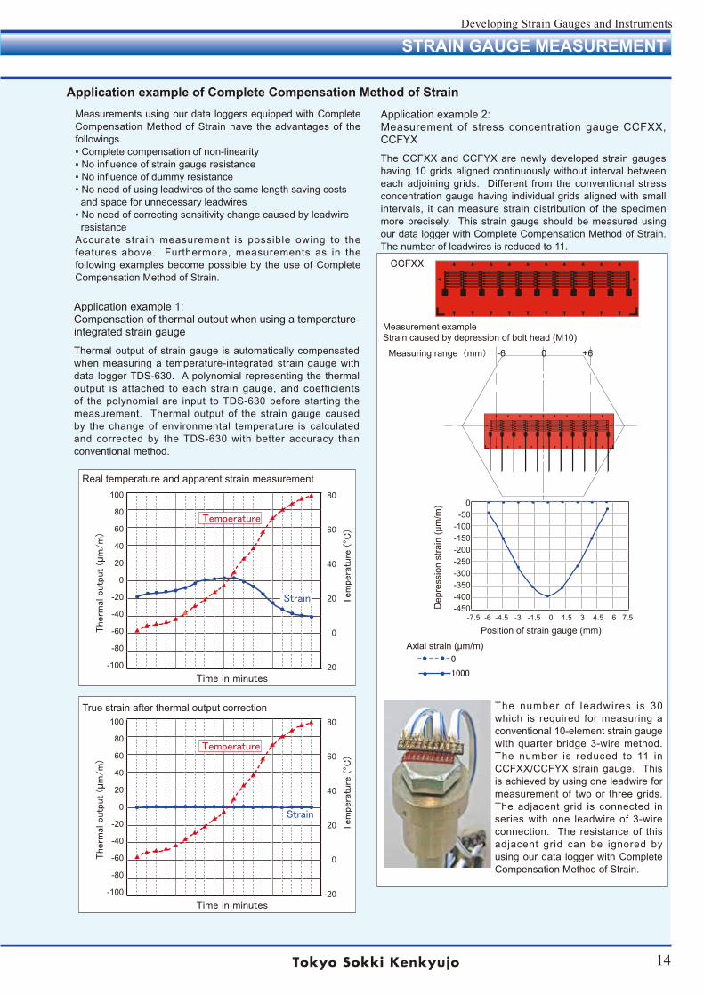
Strain gauges with leadwires and modular plugMost of our strain gauges can be supplied with the pre-attached 4 leadwires and modular plug (RJ12) that make up our proprietary 1-Gauge 4-Wire system. Because a modular plug is attached to the end of the leadwires, soldering or screwing connect ions to a measur ing inst rument is unnecessary, but the instrument must be of TML make. The 4-wire leadwires are covered with polypropylene resin which does not generate noxious gas even if exposed to fire.
Single element strain gauge with 4-wire paralleled leadwire
With 4-wire paralleled leadwire and modular plug
Three-element rectangular rosette strain gauge
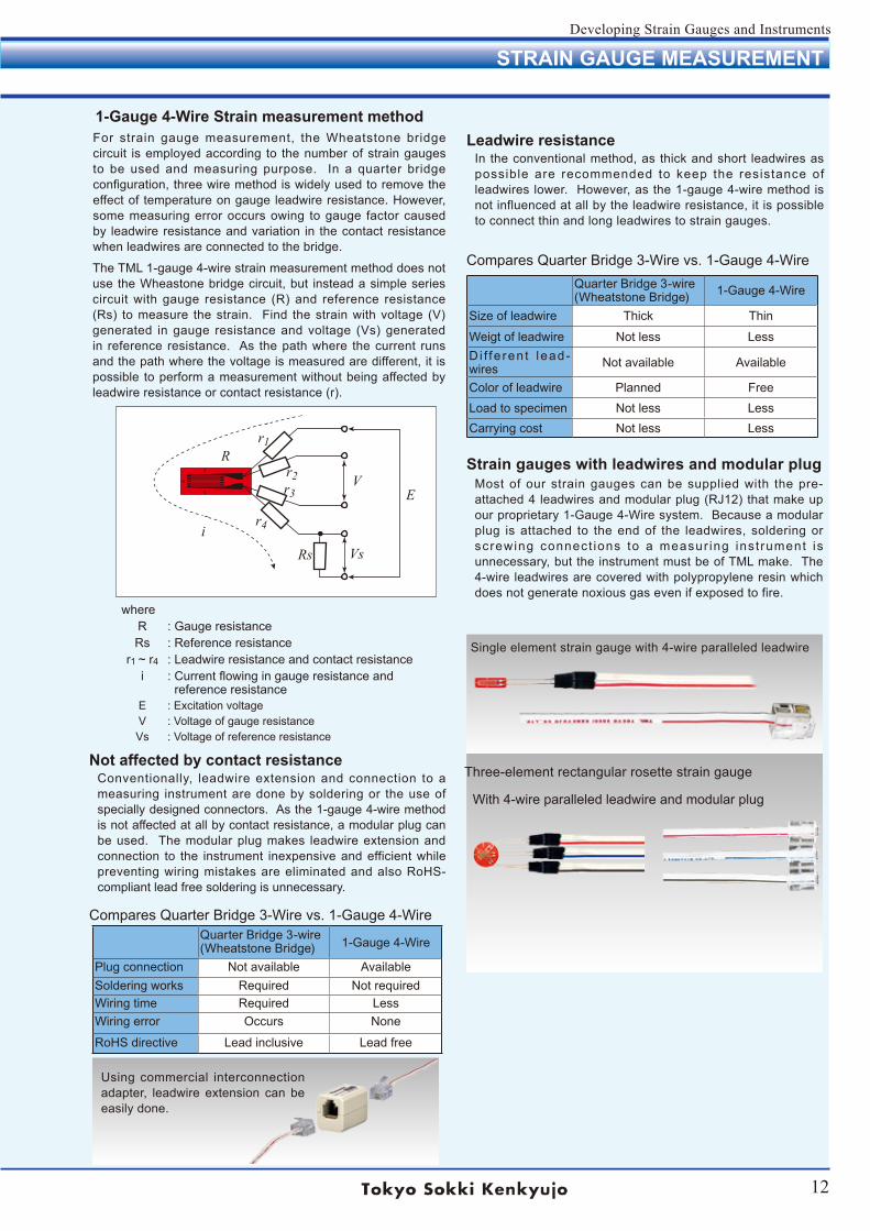
The TML 1-gauge 4-wire strain measurement method does not use the Wheastone bridge circuit, but instead a simple series circuit with gauge resistance (R) and reference resistance (Rs) to measure the strain. Find the strain with voltage (V) generated in gauge resistance and voltage (Vs) generated in reference resistance. As the path where the current runs and the path where the voltage is measured are different, it is possible to perform a measurement without being affected by leadwire resistance or contact resistance (r).
whereR : Gauge resistanceRs : Reference resistance
r1 ~ r4 : Leadwire resistance and contact resistancei : Current flowing in gauge resistance and
reference resistanceE : Excitation voltageV : Voltage of gauge resistanceVs : Voltage of reference resistance
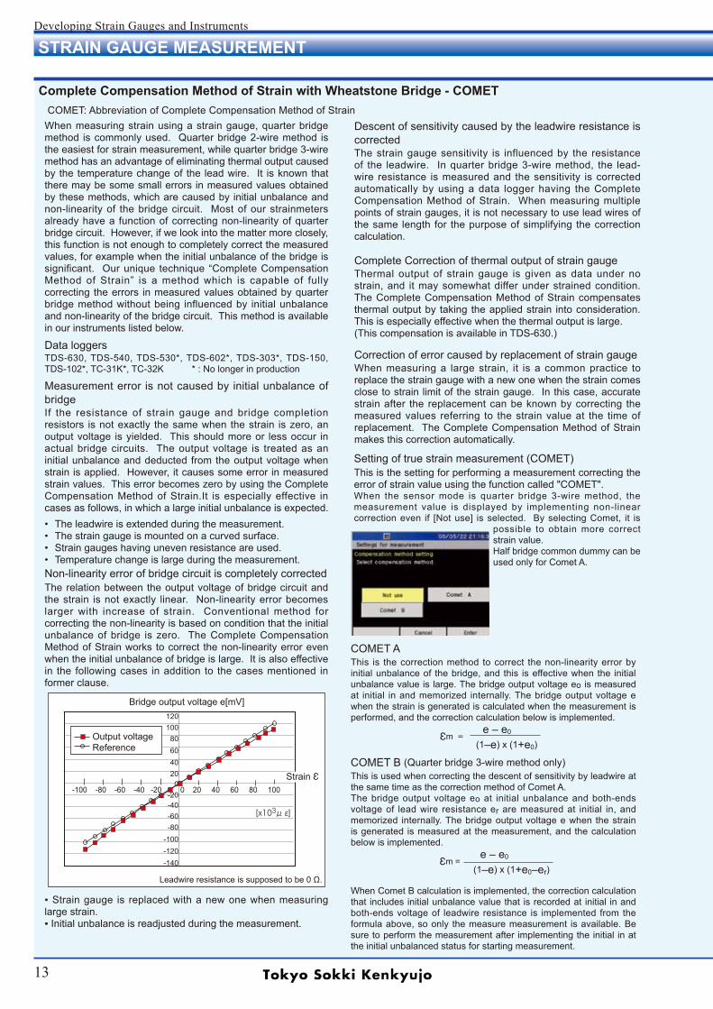
Using commercial interconnection adapter, leadwire extension can be easily done.
i
R
Rs
EV
Vs
r1
r3
r4
r2
13
Developing Strain Gauges and Instruments
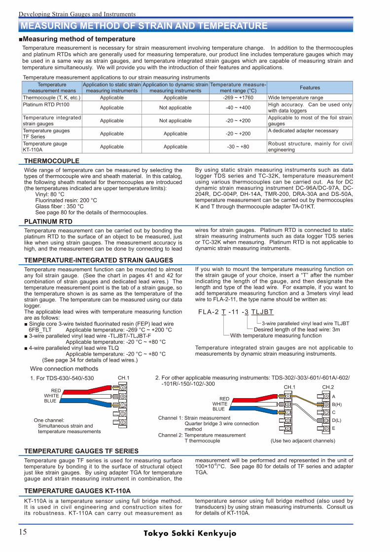
Strain gauge is replaced with a new one when measuring large strain. Initial unbalance is readjusted during the measurement.
STRAIN GAUGE MEASUREMENT
[x103με]
-100 -80 -60 -40 -20 0 20 40 60 80 100
Leadwire resistance is supposed to be 0 Ω.
Output voltageReference
Strain Ԑ
Bridge output voltage e[mV]
• The leadwire is extended during the measurement.• The strain gauge is mounted on a curved surface.• Strain gauges having uneven resistance are used.• Temperature change is large during the measurement.Non-linearity error of bridge circuit is completely correctedThe relation between the output voltage of bridge circuit and the strain is not exactly linear. Non-linearity error becomes larger with increase of strain. Conventional method for correcting the non-linearity is based on condition that the initial unbalance of bridge is zero. The Complete Compensation Method of Strain works to correct the non-linearity error even when the initial unbalance of bridge is large. It is also effective in the following cases in addition to the cases mentioned in former clause.
Complete Compensation Method of Strain with Wheatstone Bridge - COMET
When measuring strain using a strain gauge, quarter bridge method is commonly used. Quarter bridge 2-wire method is the easiest for strain measurement, while quarter bridge 3-wire method has an advantage of eliminating thermal output caused by the temperature change of the lead wire. It is known that there may be some small errors in measured values obtained by these methods, which are caused by initial unbalance and non-linearity of the bridge circuit. Most of our strainmeters already have a function of correcting non-linearity of quarter bridge circuit. However, if we look into the matter more closely, this function is not enough to completely correct the measured values, for example when the initial unbalance of the bridge is significant. Our unique technique “Complete Compensation Method of Strain” is a method which is capable of fully correcting the errors in measured values obtained by quarter bridge method without being influenced by initial unbalance and non-linearity of the bridge circuit. This method is available in our instruments listed below.
Measurement error is not caused by initial unbalance of bridgeIf the resistance of strain gauge and bridge completion resistors is not exactly the same when the strain is zero, an output voltage is yielded. This should more or less occur in actual bridge circuits. The output voltage is treated as an initial unbalance and deducted from the output voltage when strain is applied. However, it causes some error in measured strain values. This error becomes zero by using the Complete Compensation Method of Strain.It is especially effective in cases as follows, in which a large initial unbalance is expected.
120100
80604020
0-20-40-60-80
-100-120-140
COMET: Abbreviation of Complete Compensation Method of Strain
Data loggersTDS-630, TDS-540, TDS-530*, TDS-602*, TDS-303*, TDS-150, TDS-102*, TC-31K*, TC-32K * : No longer in production
Descent of sensitivity caused by the leadwire resistance is correctedThe strain gauge sensitivity is influenced by the resistance of the leadwire. In quarter bridge 3-wire method, the lead- wire resistance is measured and the sensitivity is corrected automatically by using a data logger having the Complete Compensation Method of Strain. When measuring multiple points of strain gauges, it is not necessary to use lead wires of the same length for the purpose of simplifying the correction calculation.
Complete Correction of thermal output of strain gaugeThermal output of strain gauge is given as data under no strain, and it may somewhat differ under strained condition. The Complete Compensation Method of Strain compensates thermal output by taking the applied strain into consideration. This is especially effective when the thermal output is large.(This compensation is available in TDS-630.)
Correction of error caused by replacement of strain gaugeWhen measuring a large strain, it is a common practice to replace the strain gauge with a new one when the strain comes close to strain limit of the strain gauge. In this case, accurate strain after the replacement can be known by correcting the measured values referring to the strain value at the time of replacement. The Complete Compensation Method of Strain makes this correction automatically.
Setting of true strain measurement (COMET)This is the setting for performing a measurement correcting the error of strain value using the function called "COMET". When the sensor mode is quarter bridge 3-wire method, the measurement value is displayed by implementing non-linear correction even if [Not use] is selected. By selecting Comet, it is
possible to obtain more correct strain value.Half bridge common dummy can be used only for Comet A.
COMET AThis is the correction method to correct the non-linearity error by initial unbalance of the bridge, and this is effective when the initial unbalance value is large. The bridge output voltage eo is measured at initial in and memorized internally. The bridge output voltage e when the strain is generated is calculated when the measurement is performed, and the correction calculation below is implemented. e ‒ e0 Ԑm = (1‒e) x (1+e0)
COMET B (Quarter bridge 3-wire method only)This is used when correcting the descent of sensitivity by leadwire at the same time as the correction method of Comet A.The bridge output voltage eo at initial unbalance and both-ends voltage of lead wire resistance er are measured at initial in, and memorized internally. The bridge output voltage e when the strain is generated is measured at the measurement, and the calculation below is implemented. e ‒ e0 Ԑm = (1‒e) x (1+e0‒er)
When Comet B calculation is implemented, the correction calculation that includes initial unbalance value that is recorded at initial in and both-ends voltage of leadwire resistance is implemented from the formula above, so only the measure measurement is available. Be sure to perform the measurement after implementing the initial in at the initial unbalanced status for starting measurement.
14
Developing Strain Gauges and Instruments
STRAIN GAUGE MEASUREMENT
Measurements using our data loggers equipped with Complete Compensation Method of Strain have the advantages of the followings. Complete compensation of non-linearity No influence of strain gauge resistance No influence of dummy resistance No need of using leadwires of the same length saving costs and space for unnecessary leadwires No need of correcting sensitivity change caused by leadwire resistanceAccurate strain measurement is possible owing to the features above. Furthermore, measurements as in the following examples become possible by the use of Complete Compensation Method of Strain.
Application example 1: Compensation of thermal output when using a temperature-integrated strain gauge
Thermal output of strain gauge is automatically compensated when measuring a temperature-integrated strain gauge with data logger TDS-630. A polynomial representing the thermal output is attached to each strain gauge, and coefficients of the polynomial are input to TDS-630 before starting the measurement. Thermal output of the strain gauge caused by the change of environmental temperature is calculated and corrected by the TDS-630 with better accuracy than conventional method.
Real temperature and apparent strain measurement100
80
60
40
20
0
-20
-40
-60
-80
-100
80
60
40
20
0
-20
Temperature
Tem
pera
ture
(° C
)
Strain
Therm
al o
utp
ut
(µm
/m
)
Time in minutes
100
80
60
40
20
0
-20
-40
-60
-80
-100
80
60
40
20
0
-20
Tem
pera
ture
(° C
)
Strain
Therm
al o
utp
ut
(µm
/m
)
Time in minutes
CCFXX
Measurement exampleStrain caused by depression of bolt head (M10)
Measuring range (mm) -6 0 +6
-7.5 -6 -4.5 -3 -1.5 0 1.5 3 4.5 6 7.5
0-50
-100-150-200-250-300-350-400-450
Position of strain gauge (mm)
Dep
ress
ion
stra
in (µ
m/m
)
Axial strain (µm/m)0
1000
Application example of Complete Compensation Method of Strain
True strain after thermal output correction
Application example 2: Measurement of stress concentration gauge CCFXX, CCFYX
The CCFXX and CCFYX are newly developed strain gauges having 10 grids aligned continuously without interval between each adjoining grids. Different from the conventional stress concentration gauge having individual grids aligned with small intervals, it can measure strain distribution of the specimen more precisely. This strain gauge should be measured using our data logger with Complete Compensation Method of Strain. The number of leadwires is reduced to 11.
The number of leadwires is 30 which is required for measuring a conventional 10-element strain gauge with quarter bridge 3-wire method. The number is reduced to 11 in CCFXX/CCFYX strain gauge. This is achieved by using one leadwire for measurement of two or three grids. The adjacent grid is connected in series with one leadwire of 3-wire connection. The resistance of this adjacent grid can be ignored by using our data logger with Complete Compensation Method of Strain.
Temperature
15
Developing Strain Gauges and Instruments
MEASURING METHOD OF STRAIN AND TEMPERATUREMeasuring method of temperature
Temperature measurement is necessary for strain measurement involving temperature change. In addition to the thermocouples and platinum RTDs which are generally used for measuring temperature, our product line includes temperature gauges which may be used in a same way as strain gauges, and temperature integrated strain gauges which are capable of measuring strain and temperature simultaneously. We will provide you with the introduction of their features and applications.
Temperature measurement applications to our strain measuring instrumentsTemperature
measurement meansApplication to static strain
measuring instrumentsApplication to dynamic strain
measuring instrumentsTemperature measure-
ment range (°C) Features
Thermocouple (T, K, etc.) Applicable Applicable -269 ~ +1760 Wide temperature rangePlatinum RTD Pt100 Applicable Not applicable -40 ~ +400 High accuracy. Can be used only
with data loggersTemperature integrated strain gauges Applicable Not applicable -20 ~ +200 Applicable to most of the foil strain
gaugesTemperature gaugesTF Series Applicable Applicable -20 ~ +200 A dedicated adapter necessary
Temperature gauge KT-110A Applicable Applicable -30 ~ +80 Robust structure, mainly for civil
engineering
THERMOCOUPLEWide range of temperature can be measured by selecting the types of thermocouple wire and sheath material. In this catalog, the following sheath material for thermocouples are introduced (the temperatures indicated are upper temperature limits):
Vinyl: 80 °CFluorinated resin: 200 °CGlass fiber : 350 °CSee page 80 for the details of thermocouples.
By using static strain measuring instruments such as data logger TDS series and TC-32K, temperature measurement using various thermocouples can be carried out. As for DC dynamic strain measuring instrument DC-96A/DC-97A, DC-204R, DC-004P, DH-14A, TMR-200, DRA-30A and DS-50A, temperature measurement can be carried out by thermocouples K and T through thermocouple adapter TA-01KT.
PLATINUM RTDTemperature measurement can be carried out by bonding the platinum RTD to the surface of an object to be measured, just like when using strain gauges. The measurement accuracy is high, and the measurement can be done by connecting to lead
wires for strain gauges. Platinum RTD is connected to static strain measuring instruments such as data logger TDS series or TC-32K when measuring. Platinum RTD is not applicable to dynamic strain measuring instruments.
TEMPERATURE-INTEGRATED STRAIN GAUGESTemperature measurement function can be mounted to almost any foil strain gauge. (See the chart in pages 41 and 42 for combination of strain gauges and dedicated lead wires.) The temperature measurement point is the tab of a strain gauge, so the temperature shown is as same as the temperature of the strain gauge. The temperature can be measured using our data logger. The applicable lead wires with temperature measuring function are as follows: Single core 3-wire twisted fluorinated resin (FEP) lead wire 6FB_TLT Applicable temperature: -269 °C ~ +200 °C 3-wire paralleled vinyl lead wire -TLJBT/-TLJBT-F Applicable temperature: -20 °C ~ +80 °C 4-wire paralleled vinyl lead wire TLQ Applicable temperature: -20 °C ~ +80 °C (See page 34 for details of lead wires.)
If you wish to mount the temperature measuring function on the strain gauge of your choice, insert a “T” after the number indicating the length of the gauge, and then designate the length and type of the lead wire. For example, if you want to add temperature measuring function and a 3meters vinyl lead wire to FLA-2-11, the type name should be written as:
FLA-2 T -11 -3 TLJBT 3-wire paralleled vinyl lead wire TLJBT Desired length of the lead wire: 3m With temperature measuring function
Temperature integrated strain gauges are not applicable to measurements by dynamic strain measuring instruments.
Wire connection methods1. For TDS-630/-540/-530
One channel: Simultaneous strain and temperature measurements
2. For other applicable measuring instruments: TDS-302/-303/-601/-601A/-602/ -101R/-150/-102/-300
Channel 1: Strain measurement Quarter bridge 3 wire connection method Channel 2: Temperature measurement T thermocouple (Use two adjacent channels)
CH.1
RED WHITE
BLUE RED WHITE
BLUE
CH.1 CH.2
A
B(H)
C
D(L)
E
TEMPERATURE GAUGES TF SERIES
TEMPERATURE GAUGES KT-110A
Temperature gauge TF series is used for measuring surface temperature by bonding it to the surface of structural object just like strain gauges. By using adapter TGA for temperature gauge and strain measuring instrument in combination, the
measurement will be performed and represented in the unit of 100×10-6/°C. See page 80 for details of TF series and adapter TGA.
KT-110A is a temperature sensor using full bridge method. It is used in civil engineering and construction sites for its robustness. KT-110A can carry out measurement as
temperature sensor using full bridge method (also used by transducers) by using strain measuring instruments. Consult us for details of KT-110A.
16
Developing Strain Gauges and Instruments
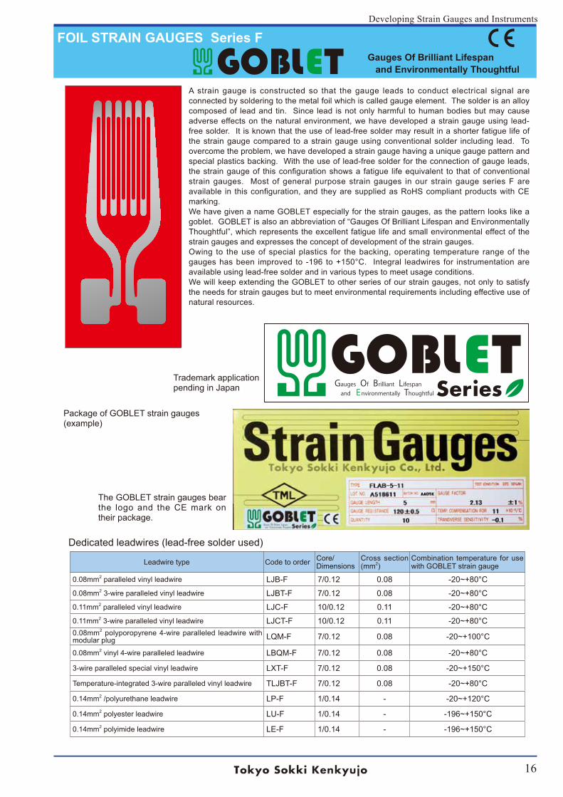
FOIL STRAIN GAUGES Series F Gauges Of Brilliant Lifespan and Environmentally Thoughtful
A strain gauge is constructed so that the gauge leads to conduct electrical signal are connected by soldering to the metal foil which is called gauge element. The solder is an alloy composed of lead and tin. Since lead is not only harmful to human bodies but may cause adverse effects on the natural environment, we have developed a strain gauge using lead-free solder. It is known that the use of lead-free solder may result in a shorter fatigue life of the strain gauge compared to a strain gauge using conventional solder including lead. To overcome the problem, we have developed a strain gauge having a unique gauge pattern and special plastics backing. With the use of lead-free solder for the connection of gauge leads, the strain gauge of this configuration shows a fatigue life equivalent to that of conventional strain gauges. Most of general purpose strain gauges in our strain gauge series F are available in this configuration, and they are supplied as RoHS compliant products with CE marking. We have given a name GOBLET especially for the strain gauges, as the pattern looks like a goblet. GOBLET is also an abbreviation of “Gauges Of Brilliant Lifespan and Environmentally Thoughtful”, which represents the excellent fatigue life and small environmental effect of the strain gauges and expresses the concept of development of the strain gauges. Owing to the use of special plastics for the backing, operating temperature range of the gauges has been improved to -196 to +150°C. Integral leadwires for instrumentation are available using lead-free solder and in various types to meet usage conditions. We will keep extending the GOBLET to other series of our strain gauges, not only to satisfy the needs for strain gauges but to meet environmental requirements including effective use of natural resources.
Package of GOBLET strain gauges (example)
Leadwire type Code to order Core/Dimensions
Cross section (mm2)
Combination temperature for use with GOBLET strain gauge
0.08mm2 paralleled vinyl leadwire LJB-F 7/0.12 0.08 -20~+80°C
0.08mm2 3-wire paralleled vinyl leadwire LJBT-F 7/0.12 0.08 -20~+80°C
0.11mm2 paralleled vinyl leadwire LJC-F 10/0.12 0.11 -20~+80°C
0.11mm2 3-wire paralleled vinyl leadwire LJCT-F 10/0.12 0.11 -20~+80°C0.08mm2 polyporopyrene 4-wire paralleled leadwire with modular plug LQM-F 7/0.12 0.08 -20~+100°C
0.08mm2 vinyl 4-wire paralleled leadwire LBQM-F 7/0.12 0.08 -20~+80°C
3-wire paralleled special vinyl leadwire LXT-F 7/0.12 0.08 -20~+150°C
Temperature-integrated 3-wire paralleled vinyl leadwire TLJBT-F 7/0.12 0.08 -20~+80°C
0.14mm2 /polyurethane leadwire LP-F 1/0.14 - -20~+120°C
0.14mm2 polyester leadwire LU-F 1/0.14 - -196~+150°C
0.14mm2 polyimide leadwire LE-F 1/0.14 - -196~+150°C
The GOBLET strain gauges bear the logo and the CE mark on their package.
Trademark applicationpending in Japan
Dedicated leadwires (lead-free solder used)
17
Developing Strain Gauges and Instruments
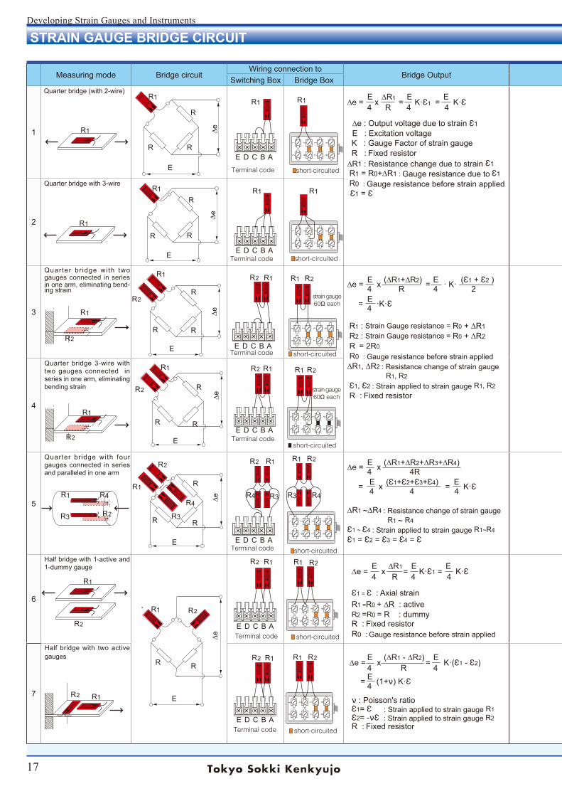
STRAIN GAUGE BRIDGE CIRCUIT
Measuring mode Bridge circuitWiring connection to
Bridge OutputSwitching Box Bridge Box
1
Quarter bridge (with 2-wire)
E ∆R1 E E ∆e = x = K·Ԑ1 = K·Ԑ 4 R 4 4 ∆e : Output voltage due to strain Ԑ1
E : Excitation voltage K : Gauge Factor of strain gauge R : Fixed resistor ∆R1 : Resistance change due to strain Ԑ1 R1 = R0+∆R1 : Gauge resistance due to Ԑ1 R0 : Gauge resistance before strain applied Ԑ1 = Ԑ
2
Quarter bridge with 3-wire
3
Quarter br idge wi th two gauges connected in series in one arm, eliminating bend-ing strain
E (∆R1+∆R2) E (Ԑ1 + Ԑ2 ) ∆e = x = · K· 4 R 4 2 E = ·K·Ԑ 4
R1 : Strain Gauge resistance = R0 + ∆R1 R2 : Strain Gauge resistance = R0 + ∆R2 R = 2R0 R0 : Gauge resistance before strain applied ∆R1, ∆R2 : Resistance change of strain gauge R1, R2
Ԑ1, Ԑ2 : Strain applied to strain gauge R1, R2
R : Fixed resistor 4
Quarter bridge 3-wire with two gauges connected in series in one arm, eliminating bending strain
5
Quarter br idge with four gauges connected in series and paralleled in one arm
E (∆R1+∆R2+∆R3+∆R4) ∆e = x 4 4R E (Ԑ1+Ԑ2+Ԑ3+Ԑ4) E = x = K·Ԑ 4 4 4 ∆R1 ~∆R4 : Resistance change of strain gauge R1 ~ R4
Ԑ1 ~ Ԑ4 : Strain applied to strain gauge R1~R4
Ԑ1 = Ԑ2 = Ԑ3 = Ԑ4 = Ԑ
6
Half bridge with 1-active and 1-dummy gauge
E ∆R1 E E ∆e = x = K·Ԑ1 = K·Ԑ 4 R 4 4
Ԑ1 = Ԑ : Axial strain R1 =R0 + ∆R : active R2 =R0 = R : dummy R : Fixed resistor R0 : Gauge resistance before strain applied
7
Half bridge with two active gauges
E (∆R1 - ∆R2) E ∆e = x = K·(Ԑ1 - Ԑ2) 4 R 4 E = (1+ν) K·Ԑ 4
ν : Poisson's ratio Ԑ1= Ԑ : Strain applied to strain gauge R1 Ԑ2= -νԐ : Strain applied to strain gauge R2 R : Fixed resistor
5 6 7 8
1 2 3 4
5 6 7 8
1 2 3 4
5 6 7 8
1 2 3 4
5 6 7 8
1 2 3 4
5 6 7 8
1 2 3 4
5 6 7 8
1 2 3 4
5 6 7 8
1 2 3 4
R1
R1 R1 R1
R1
R1 R1 R1
R1
R1
R1
R1
R1
R
R
R
RR
R
R R
R
R
R
RR
R
R
R
R2
R2
R2
R2
R2
R2
R2
R2
R2
R2
R2
R2
R2
R2
R2
R2
R2 R2
R
R1 R1 R1
R1
R1
R1
R1 R1
R4R3
R3
R4
R3
R4R3R4
R1
R1
R1 R1
R1 R1R2
E D C B A
E D C B A
E D C B A
E D C B A
E D C B A
E D C B A
E D C B AE
E
E
E
E
E
∆e∆e
∆e∆e
∆e∆e
Terminal code
Terminal code
Terminal code
Terminal code
Terminal code
Terminal code
Terminal code
strain gauge60Ω each
strain gauge60Ω each
short-circuited
short-circuited
short-circuited
short-circuited
short-circuited
short-circuited
short-circuited
18
Developing Strain Gauges and Instruments
STRAIN GAUGE BRIDGE CIRCUIT
Measuring mode Bridge circuitWiring connection to
Bridge OutputSwitching Box Bridge Box
1
Quarter bridge (with 2-wire)
E ∆R1 E E ∆e = x = K·Ԑ1 = K·Ԑ 4 R 4 4 ∆e : Output voltage due to strain Ԑ1
E : Excitation voltage K : Gauge Factor of strain gauge R : Fixed resistor ∆R1 : Resistance change due to strain Ԑ1 R1 = R0+∆R1 : Gauge resistance due to Ԑ1 R0 : Gauge resistance before strain applied Ԑ1 = Ԑ
2
Quarter bridge with 3-wire
3
Quarter br idge wi th two gauges connected in series in one arm, eliminating bend-ing strain
E (∆R1+∆R2) E (Ԑ1 + Ԑ2 ) ∆e = x = · K· 4 R 4 2 E = ·K·Ԑ 4
R1 : Strain Gauge resistance = R0 + ∆R1 R2 : Strain Gauge resistance = R0 + ∆R2 R = 2R0 R0 : Gauge resistance before strain applied ∆R1, ∆R2 : Resistance change of strain gauge R1, R2
Ԑ1, Ԑ2 : Strain applied to strain gauge R1, R2
R : Fixed resistor 4
Quarter bridge 3-wire with two gauges connected in series in one arm, eliminating bending strain
5
Quarter br idge with four gauges connected in series and paralleled in one arm
E (∆R1+∆R2+∆R3+∆R4) ∆e = x 4 4R E (Ԑ1+Ԑ2+Ԑ3+Ԑ4) E = x = K·Ԑ 4 4 4 ∆R1 ~∆R4 : Resistance change of strain gauge R1 ~ R4
Ԑ1 ~ Ԑ4 : Strain applied to strain gauge R1~R4
Ԑ1 = Ԑ2 = Ԑ3 = Ԑ4 = Ԑ
6
Half bridge with 1-active and 1-dummy gauge
E ∆R1 E E ∆e = x = K·Ԑ1 = K·Ԑ 4 R 4 4
Ԑ1 = Ԑ : Axial strain R1 =R0 + ∆R : active R2 =R0 = R : dummy R : Fixed resistor R0 : Gauge resistance before strain applied
7
Half bridge with two active gauges
E (∆R1 - ∆R2) E ∆e = x = K·(Ԑ1 - Ԑ2) 4 R 4 E = (1+ν) K·Ԑ 4
ν : Poisson's ratio Ԑ1= Ԑ : Strain applied to strain gauge R1 Ԑ2= -νԐ : Strain applied to strain gauge R2 R : Fixed resistor
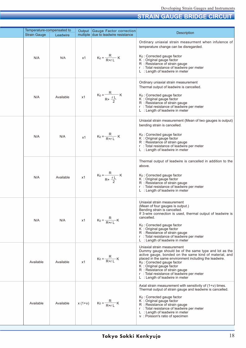
Temperature-compensated to Output multiple
Gauge Factor correction due to leadwire resistance Description Strain Gauge Leadwire
N/A N/A x1 R K0 = K R+r L
Ordinary uniaxial strain measurment when infulence of temperature change can be disregarded.
K0 : Corrected gauge factorK : Original gauge factorR : Resistance of strain gauger : Total resistance of leadwire per meterL : Length of leadwire in meter
N/A Available x1 R K0 = K r L R+ 2
Ordinary uniaxial strain measurement Thermal output of leadwire is cancelled.
K0 : Corrected gauge factorK : Original gauge factorR : Resistance of strain gauger : Total resistance of leadwire per meterL : Length of leadwire in meter
N/A N/A x1 R K0 = K R+r L
Uniaxial strain measurement (Mean of two gauges is output) bending strain is cancelled.
K0 : Corrected gauge factorK : Original gauge factorR : Resistance of strain gauger : Total resistance of leadwire per meterL : Length of leadwire in meter
N/A Available x1 R K0 = K r L R+ 2
Thermal output of leadwire is cancelled in addition to the above.
K0 : Corrected gauge factorK : Original gauge factorR : Resistance of strain gauger : Total resistance of leadwire per meterL : Length of leadwire in meter
N/A N/A x1 R K0 = K R+r L
Uniaxial strain measurement (Mean of four gauges is output.)Bending strain is cancelled.If 3-wire connection is used, thermal output of leadwire is cancelled.
K0 : Corrected gauge factorK : Original gauge factorR : Resistance of strain gauger : Total resistance of leadwire per meterL : Length of leadwire in meter
Available Available x1 R K0 = K R+r L
Uniaxial strain measurement Dummy gauge should be of the same type and lot as the active gauge, bonded on the same kind of material, and placed in the same environment including the leadwire.K0 : Corrected gauge factorK : Original gauge factorR : Resistance of strain gauger : Total resistance of leadwire per meterL : Length of leadwire in meter
Available Available x (1+ν) R K0 = K R+r L
Axial strain measurement with sensitivity of (1+ν) times.Thermal output of strain gauge and leadwire is cancelled.
K0 : Corrected gauge factorK : Original gauge factorR : Resistance of strain gauger : Total resistance of leadwire per meterL : Length of leadwire in meterν : Poisson's ratio of specimen
19
Developing Strain Gauges and Instruments
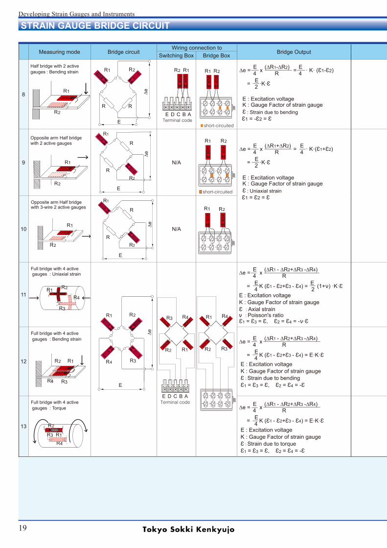
STRAIN GAUGE BRIDGE CIRCUIT
Measuring mode Bridge circuitWiring connection to
Bridge OutputSwitching Box Bridge Box
8
Half bridge with 2 active gauges : Bending strain
E (∆R1-∆R2) E ∆e = x = · K· (Ԑ1-Ԑ2) 4 R 4 E = ·K·Ԑ 2
E : Excitation voltage K : Gauge Factor of strain gauge Ԑ : Strain due to bending Ԑ1 = -Ԑ2 = Ԑ
9
Opposite arm Half bridge with 2 active gauges
N/A
E (∆R1+∆R2) E ∆e = x = · K·(Ԑ1+Ԑ2) 4 R 4 E = ·K·Ԑ 2
E : Excitation voltage K : Gauge Factor of strain gauge Ԑ : Uniaxial strain Ԑ1 = Ԑ2 = Ԑ
10
Opposite arm Half bridge with 3-wire 2 active gauges
N/A
11
Full bridge with 4 active gauges : Uniaxial strain
12
Full bridge with 4 active gauges : Bending strain
13
Full bridge with 4 active gauges : Torque
R2
R2
R2
R1
R1
R1
R1
R1 R1
R4
R3
R2
R2
R2
R2
R2
R1
R1
R1
R1
R3
R4
R4 R3
R2
R
R
R1
E
R2
RR
R2R1
E
∆e
R
R
R1
E
∆e
R2
R2R1
E
∆e
R4 R3R2
E D C B ATerminal code
5 6 7 8
1 2 3 4
5 6 7 8
1 2 3 4
5 6 7 8
1 2 3 4
R1
R3 R4
R2
E D C B ATerminal code 5 6 7 8
1 2 3 4
R3
R1 R4
R2
E (∆R1 - ∆R2+∆R3 -∆R4) ∆e = x 4 R E E = K (Ԑ1 - Ԑ2+Ԑ3 - Ԑ4) = (1+ν) ·K·Ԑ 4 2 E : Excitation voltage K : Gauge Factor of strain gauge Ԑ : Axial strain ν : Poisson's ratio Ԑ1 = Ԑ3 = Ԑ, Ԑ2 = Ԑ4 = -ν·Ԑ
E (∆R1 - ∆R2+∆R3 -∆R4) ∆e = x 4 R E = K (Ԑ1 - Ԑ2+Ԑ3 - Ԑ4) = E·K·Ԑ 4 E : Excitation voltage K : Gauge Factor of strain gauge Ԑ : Strain due to bending Ԑ1 = Ԑ3 = Ԑ, Ԑ2 = Ԑ4 = -Ԑ
E (∆R1 - ∆R2+∆R3 -∆R4) ∆e = x 4 R E = K (Ԑ1 - Ԑ2+Ԑ3 - Ԑ4) = E·K·Ԑ 4 E : Excitation voltage K : Gauge Factor of strain gauge Ԑ : Strain due to torque Ԑ1 = Ԑ3 = Ԑ, Ԑ2 = Ԑ4 = -Ԑ
short-circuited
short-circuited
∆e
20
Developing Strain Gauges and Instruments
STRAIN GAUGE BRIDGE CIRCUIT
Measuring mode Bridge circuitWiring connection to
Bridge OutputSwitching Box Bridge Box
8
Half bridge with 2 active gauges : Bending strain
E (∆R1-∆R2) E ∆e = x = · K· (Ԑ1-Ԑ2) 4 R 4 E = ·K·Ԑ 2
E : Excitation voltage K : Gauge Factor of strain gauge Ԑ : Strain due to bending Ԑ1 = -Ԑ2 = Ԑ
9
Opposite arm Half bridge with 2 active gauges
N/A
E (∆R1+∆R2) E ∆e = x = · K·(Ԑ1+Ԑ2) 4 R 4 E = ·K·Ԑ 2
E : Excitation voltage K : Gauge Factor of strain gauge Ԑ : Uniaxial strain Ԑ1 = Ԑ2 = Ԑ
10
Opposite arm Half bridge with 3-wire 2 active gauges
N/A
11
Full bridge with 4 active gauges : Uniaxial strain
12
Full bridge with 4 active gauges : Bending strain
13
Full bridge with 4 active gauges : Torque
Temperature-compensated to Output multiple
Gauge Factor correction due to leadwire resistance Description Strain Gauge Leadwire
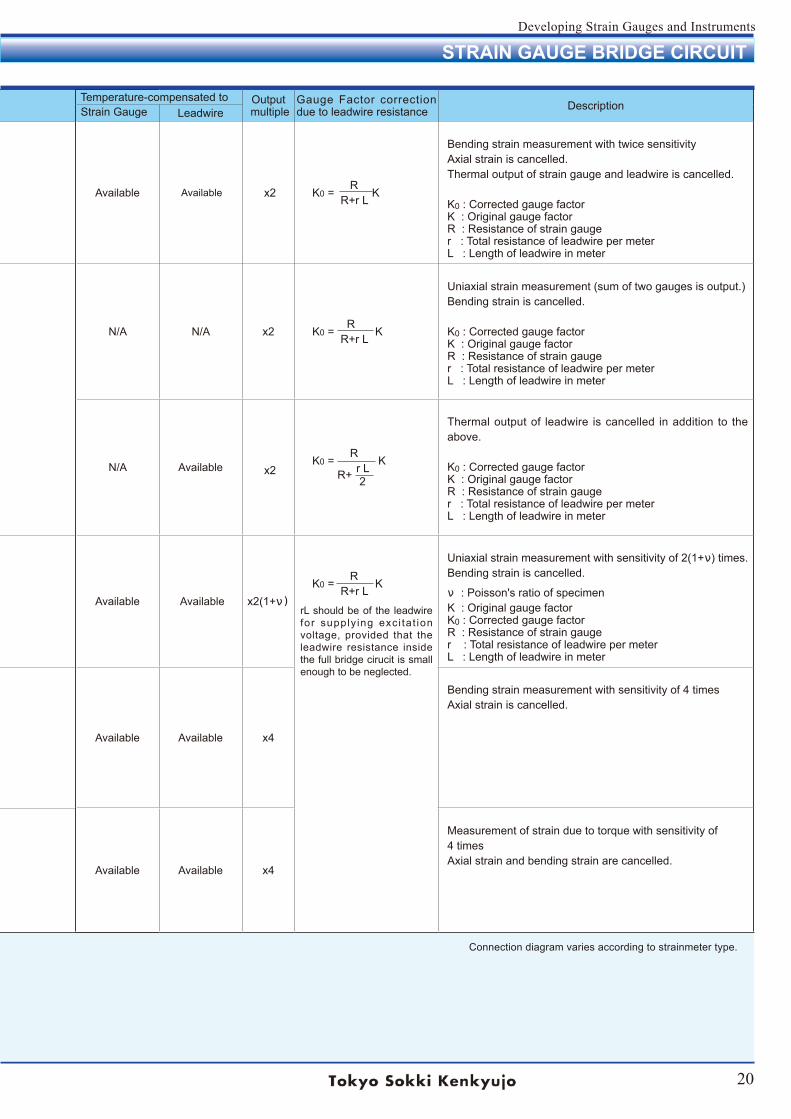
Available Available x2 R K0 = K R+r L
Bending strain measurement with twice sensitivityAxial strain is cancelled.Thermal output of strain gauge and leadwire is cancelled.
K0 : Corrected gauge factorK : Original gauge factorR : Resistance of strain gauger : Total resistance of leadwire per meterL : Length of leadwire in meter
N/A N/A x2 R K0 = K R+r L
Uniaxial strain measurement (sum of two gauges is output.)Bending strain is cancelled.
K0 : Corrected gauge factorK : Original gauge factorR : Resistance of strain gauger : Total resistance of leadwire per meterL : Length of leadwire in meter
N/A Available x2 R K0 = K r L R+ 2
Thermal output of leadwire is cancelled in addition to the above.
K0 : Corrected gauge factorK : Original gauge factorR : Resistance of strain gauger : Total resistance of leadwire per meterL : Length of leadwire in meter
Available Available x2(1+ν)
R K0 = K R+r L
rL should be of the leadwire for supply ing exci tat ion voltage, provided that the leadwire resistance inside the full bridge cirucit is small enough to be neglected.
Uniaxial strain measurement with sensitivity of 2(1+ν) times.Bending strain is cancelled.
ν : Poisson's ratio of specimenK : Original gauge factorK0 : Corrected gauge factorR : Resistance of strain gauger : Total resistance of leadwire per meterL : Length of leadwire in meter
Available Available x4
Bending strain measurement with sensitivity of 4 timesAxial strain is cancelled.
Available Available x4
Measurement of strain due to torque with sensitivity of4 times Axial strain and bending strain are cancelled.
Connection diagram varies according to strainmeter type.
21
Developing Strain Gauges and Instruments
TML STRAIN GAUGE CODING SYSTEM
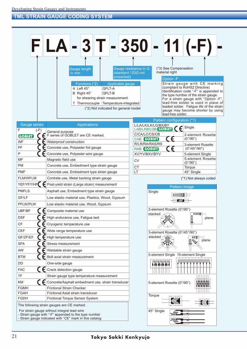
F LA - 3 T - 350 - 11 (-F) - 3 LJB(- F)Gauge resistance in Ω(standard 120Ω not presented)
Gauge length in mm
(*1) Not always coded
(*2) Not indicated for general model
Gauge series ApplicationsF (-F) General purpose
F series of GOBLET are CE marked.
WF Waterproof constructionPF Concrete use, Polyester foil gauge
P Concrete use, Polyester wire gaugeMF Magnetic field use
PM Concrete use, Embedment type strain gauge
PMF Concrete use, Embedment type strain gauge
FLM/WFLM Contrete use, Metal backing strain gauge
YEF/YF/YHF Post-yield strain (Large strain) measurement
PMFLS Asphalt use, Embedment type strain gauge
GF/LF Low elastic material use, Plastics, Wood, Gypsum
PFLW/PLW Low elastic material use, Wood, Gypsum
UBF/BF Composite material use
DSF High endurance use, Fatigue test
CF Cryogenic temperature use
CEF Wide range temperature use
QF/ZF/EF High temperature use
SFA Stress measurement
AW Weldable strain gauge
BTM Bolt axial strain measurement
DD One-side gauge
FAC Crack detection gauge
TF Strain gauge type temperature measurement
KM Concrete/Asphalt embedment use, strain transducer
FGMH Frictional Strain CheckerFGAH Frictional Axial strain transducerFGDH Frictional Torque Sensor System
Pattern imageSingle
2-element Rosette (0°/90°)
3-element Rosette (0°/45°/90°)
5-element Single 10-element Single
5-element Rosette (0°/90°)
Torque
45° Single
Pattern configuration (*1)L/LA/LK/LX/LG/BX/BYLAB/LKB/LGB Single
C/CA/LC/CS/CB 2-element Rosette (0°/90°)CAB
R/LR/RA/RAS/RS 3-element Rosette (0°/45°/90°)RAB
XV/YV/BXV/BYV 5-element Single
CV 5-element Rosette (0°/90°)
CT TorqueLT 45° Single
stacked
stacked
plane
plane
GOBLET
GOBLET
GOBLET
Functions (*2) Applicable gaugeA Left 45° QFLT-AB Right 45° QFLT-B
for shearing strain measurementT Thermocouple Temperature-integrated
S t ra in gauge w i th CE mark ing (compliant to RoHS2 Directive)Identification code “-F” is appended to the type number of the strain gauge. For a strain gauge with “Option -F”, lead-free solder is used in place of leaded solder. Fatigue life of the strain gauge may become shorter by using lead-free solder.
Option -F
(*3) See Compensationmaterial right
GOBLET
The following strain gauges are CE marked. For strain gauge without integral lead wire- Strain gauge with “-F” appended to the type number- Strain gauge indicated with “CE” mark in this catalog
22
Developing Strain Gauges and Instruments
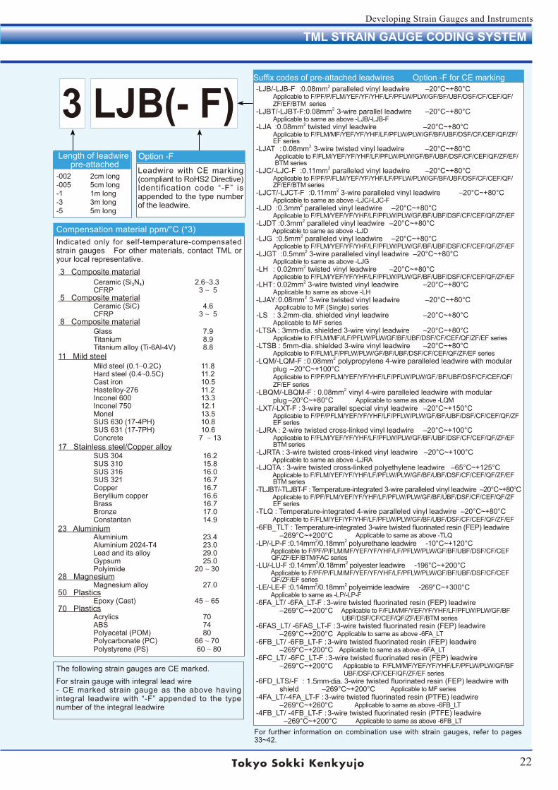
F LA - 3 T - 350 - 11 (-F) - 3 LJB(- F)Length of leadwire
pre-attached-002 2cm long-005 5cm long-1 1m long-3 3m long-5 5m long
Compensation material ppm/°C (*3)
3 Composite material
5 Composite material
8 Composite material
11 Mild steel
17 Stainless steel/Copper alloy
23 Aluminium
28 Magnesium
50 Plastics
70 Plastics
Ceramic (Si3N4) 2.6~3.3CFRP 3 ~ 5
Ceramic (SiC) 4.6CFRP 3 ~ 5
Glass 7.9Titanium 8.9Titanium alloy (Ti-6Al-4V) 8.8
Mild steel (0.1~0.2C) 11.8Hard steel (0.4~0.5C) 11.2Cast iron 10.5Hastelloy-276 11.2Inconel 600 13.3Inconel 750 12.1Monel 13.5SUS 630 (17-4PH) 10.8SUS 631 (17-7PH) 10.6Concrete 7 ~ 13
SUS 304 16.2SUS 310 15.8SUS 316 16.0SUS 321 16.7Copper 16.7Beryllium copper 16.6Brass 16.7Bronze 17.0Constantan 14.9
Aluminium 23.4Aluminium 2024-T4 23.0Lead and its alloy 29.0Gypsum 25.0Polyimide 20 ~ 30
Magnesium alloy 27.0
Epoxy (Cast) 45 ~ 65
Acrylics 70ABS 74Polyacetal (POM) 80Polycarbonate (PC) 66 ~ 70Polystyrene (PS) 60 ~ 80
Indicated only for self-temperature-compensated strain gauges For other materials, contact TML or your local representative.
TML STRAIN GAUGE CODING SYSTEM
Suffix codes of pre-attached leadwires Option -F for CE marking
For further information on combination use with strain gauges, refer to pages 33~42.
-LJB/-LJB-F :0.08mm2 paralleled vinyl leadwire ‒20°C~+80°C Applicable to F/PF/P/FLM/YEF/YF/YHF/LF/PFLW/PLW/GF/BF/UBF/DSF/CF/CEF/QF/ ZF/EF/BTM series -LJBT/-LJBT-F:0.08mm2 3-wire parallel leadwire ‒20°C~+80°C Applicable to same as above -LJB/-LJB-F -LJA :0.08mm2 twisted vinyl leadwire ‒20°C~+80°C Applicable to F/FLM/MF/YEF/YF/YHF/LF/PFLW/PLW/GF/BF/UBF/DSF/CF/CEF/QF/ZF/ EF series -LJAT : 0.08mm2 3-wire twisted vinyl leadwire ‒20°C~+80°C Applicable to F/FLM/YEF/YF/YHF/LF/PFLW/PLW/GF/BF/UBF/DSF/CF/CEF/QF/ZF/EF/ BTM series -LJC/-LJC-F :0.11mm2 paralleled vinyl leadwire ‒20°C~+80°C Applicable to F/PF/P/FLM/YEF/YF/YHF/LF/PFLW/PLW/GF/BF/UBF/DSF/CF/CEF/QF/ ZF/EF/BTM series -LJCT/-LJCT-F :0.11mm2 3-wire paralleled vinyl leadwire ‒20°C~+80°C Applicable to same as above -LJC/-LJC-F -LJD :0.3mm2 paralleled vinyl leadwire ‒20°C~+80°C Applicable to F/FLM/YEF/YF/YHF/LF/PFLW/PLW/GF/BF/UBF/DSF/CF/CEF/QF/ZF/EF -LJDT :0.3mm2 paralleled vinyl leadwire ‒20°C~+80°C Applicable to same as above -LJD -LJG :0.5mm2 paralleled vinyl leadwire ‒20°C~+80°C Applicable to F/FLM/YEF/YF/YHF/LF/PFLW/PLW/GF/BF/UBF/DSF/CF/CEF/QF/ZF/EF -LJGT :0.5mm2 3-wire paralleled vinyl leadwire ‒20°C~+80°C Applicable to same as above -LJG -LH : 0.02mm2 twisted vinyl leadwire ‒20°C~+80°C Applicable to F/FLM/YEF/YF/YHF/LF/PFLW/PLW/GF/BF/UBF/DSF/CF/CEF/QF/ZF/EF -LHT : 0.02mm2 3-wire twisted vinyl leadwire ‒20°C~+80°C Applicable to same as above -LH -LJAY: 0.08mm2 3-wire twisted vinyl leadwire ‒20°C~+80°C Applicable to MF (Single) series -LS : 3.2mm-dia. shielded vinyl leadwire ‒20°C~+80°C Applicable to MF series -LTSA : 3mm-dia. shielded 3-wire vinyl leadwire ‒20°C~+80°C Applicable to F/FLM/MF//LF/PFLW/PLW/GF/BF/UBF/DSF/CF/CEF/QF/ZF/EF series -LTSB : 5mm-dia. shielded 3-wire vinyl leadwire ‒20°C~+80°C Applicable to F/FLM/LF/PFLW/PLW/GF/BF/UBF/DSF/CF/CEF/QF/ZF/EF series -LQM/-LQM-F : 0.08mm2 polypropylene 4-wire paralleled leadwire with modular plug ‒20°C~+100°C Applicable to F/PF/PFLM/YEF/YF/YHF/LF/PFLW/PLW/GF/BF/UBF/DSF/CF/CEF/QF/ ZF/EF series -LBQM/-LBQM-F : 0.08mm2 vinyl 4-wire paralleled leadwire with modular plug ‒20°C~+80°C Applicable to same as above -LQM -LXT/-LXT-F : 3-wire parallel special vinyl leadwire ‒20°C~+150°C Applicable to F/PF/PFLM/YEF/YF/YHF/LF/PFLW/PLW/GF/BF/UBF/DSF/CF/CEF/QF/ZF EF series -LJRA : 2-wire twisted cross-linked vinyl leadwire ‒20°C~+100°C Applicable to F/FLM/YEF/YF/YHF/LF/PFLW/PLW/GF/BF/UBF/DSF/CF/CEF/QF/ZF/EF BTM series -LJRTA : 3-wire twisted cross-linked vinyl leadwire ‒20°C~+100°C Applicable to same as above -LJRA -LJQTA : 3-wire twisted cross-linked polyethylene leadwire ‒65°C~+125°C Applicable to F/FLM/YEF/YF/YHF/LF/PFLW/PLW/GF/BF/UBF/DSF/CF/CEF/QF/ZF/EF BTM series -TLJBT/-TLJBT-F : Temperature-integrated 3-wire paralleled vinyl leadwire ‒20°C~+80°C Applicable to F/PF/FLM/YEF/YF/YHF/LF/PFLW/PLW/GF/BF/UBF/DSF/CF/CEF/QF/ZF EF series -TLQ : Temperature-integrated 4-wire paralleled vinyl leadwire ‒20°C~+80°C Applicable to F/FLM/YEF/YF/YHF/LF/PFLW/PLW/GF/BF/UBF/DSF/CF/CEF/QF/ZF/EF -6FB_TLT : Temperature-integrated 3-wire twisted fluorinated resin (FEP) leadwire ‒269°C~+200°C Applicable to same as above -TLQ -LP/-LP-F :0.14mm2/0.18mm2 polyurethane leadwire -10°C~+120°C Applicable to F/PF/P/FLM/MF/YEF/YF/YHF/LF/PFLW/PLW/GF/BF/UBF/DSF/CF/CEF QF/ZF/EF/BTM/FAC series -LU/-LU-F :0.14mm2/0.18mm2 polyester leadwire -196°C~+200°C Applicable to F/PF/P/FLM/MF/YEF/YF/YHF/LF/PFLW/PLW/GF/BF/UBF/DSF/CF/CEF QF/ZF/EF series -LE/-LE-F :0.14mm2/0.18mm2 polyeimide leadwire -269°C~+300°C Applicable to same as -LP/-LP-F -6FA_LT/ -6FA_LT-F : 3-wire twisted fluorinated resin (FEP) leadwire ‒269°C~+200°C Applicable to F/FLM/MF/YEF/YF/YHF/LF/PFLW/PLW/GF/BF UBF/DSF/CF/CEF/QF/ZF/EF/BTM series -6FAS_LT/ -6FAS_LT-F : 3-wire twisted fluorinated resin (FEP) leadwire ‒269°C~+200°C Applicable to same as above -6FA_LT -6FB_LT/ -6FB_LT-F : 3-wire twisted fluorinated resin (FEP) leadwire ‒269°C~+200°C Applicable to same as above -6FA_LT -6FC_LT/ -6FC_LT-F : 3-wire twisted fluorinated resin (FEP) leadwire ‒269°C~+200°C Applicable to F/FLM/MF/YEF/YF/YHF/LF/PFLW/PLW/GF/BF UBF/DSF/CF/CEF/QF/ZF/EF series -6FD_LTS/-F : 1.5mm-dia. 3-wire twisted fluorinated resin (FEP) leadwire with shield ‒269°C~+200°C Applicable to MF series -4FA_LT/-4FA_LT-F : 3-wire twisted fluorinated resin (PTFE) leadwire ‒269°C~+260°C Applicable to same as above -6FB_LT -4FB_LT/ -4FB_LT-F : 3-wire twisted fluorinated resin (PTFE) leadwire ‒269°C~+200°C Applicable to same as above -6FB_LT
Leadwire with CE marking (compliant to RoHS2 Directive)Identification code “-F” is appended to the type number of the leadwire.
Option -F
The following strain gauges are CE marked.For strain gauge with integral lead wire- CE marked strain gauge as the above having integral leadwire with “-F” appended to the type number of the integral leadwire
23
Developing Strain Gauges and Instruments
PACKAGE DESIGNATION
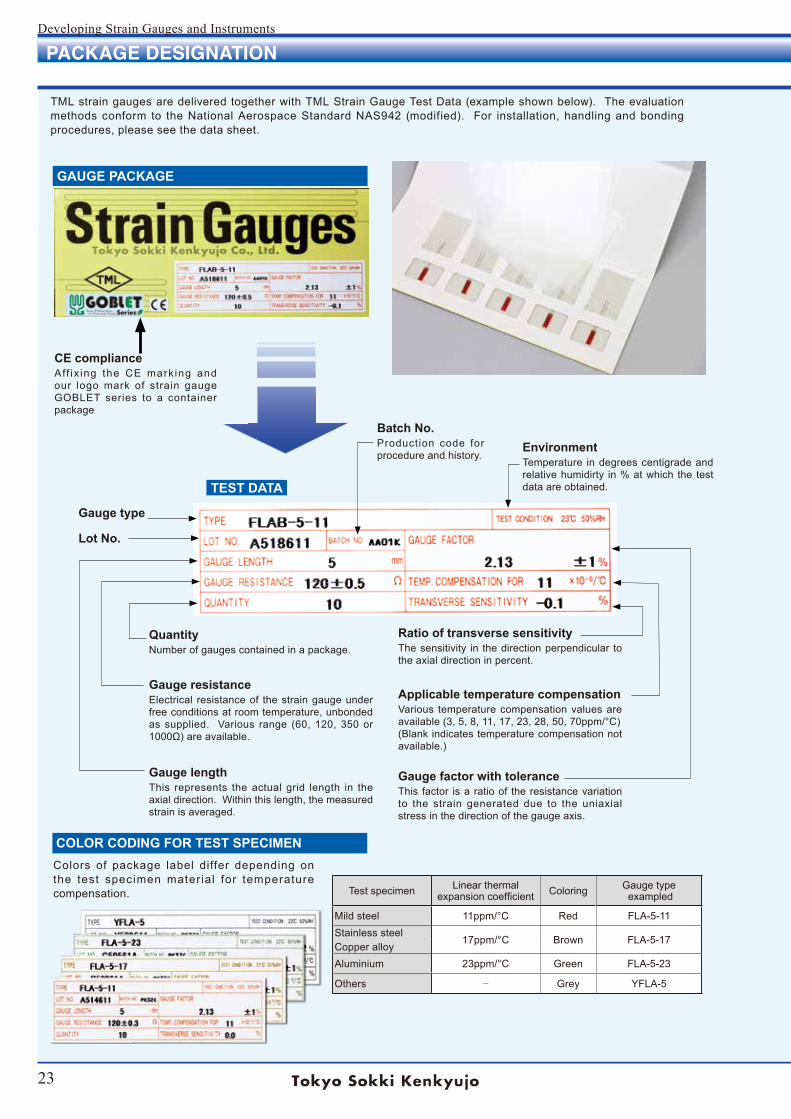
TML strain gauges are delivered together with TML Strain Gauge Test Data (example shown below). The evaluation methods conform to the National Aerospace Standard NAS942 (modified). For installation, handling and bonding procedures, please see the data sheet.
GAUGE PACKAGE
TEST DATA
COLOR CODING FOR TEST SPECIMEN
Test specimen Linear thermalexpansion coefficient Coloring Gauge type
exampled
Mild steel 11ppm/°C Red FLA-5-11Stainless steel
17ppm/°C Brown FLA-5-17Copper alloyAluminium 23ppm/°C Green FLA-5-23
Others − Grey YFLA-5
Colors of package label differ depending on the test specimen material for temperature compensation.
Batch No.Production code for procedure and history.
EnvironmentTemperature in degrees centigrade and relative humidirty in % at which the test data are obtained.
Ratio of transverse sensitivityThe sensitivity in the direction perpendicular to the axial direction in percent.
Applicable temperature compensationVarious temperature compensation values are available (3, 5, 8, 11, 17, 23, 28, 50, 70ppm/°C)(Blank indicates temperature compensation not available.)
Gauge factor with toleranceThis factor is a ratio of the resistance variation to the strain generated due to the uniaxial stress in the direction of the gauge axis.
QuantityNumber of gauges contained in a package.
Gauge resistanceElectrical resistance of the strain gauge under free conditions at room temperature, unbonded as supplied. Various range (60, 120, 350 or 1000Ω) are available.
Gauge lengthThis represents the actual grid length in the axial direction. Within this length, the measured strain is averaged.
Gauge type
Lot No.
CE complianceAff ix ing the CE mark ing and our logo mark of strain gauge GOBLET series to a container package
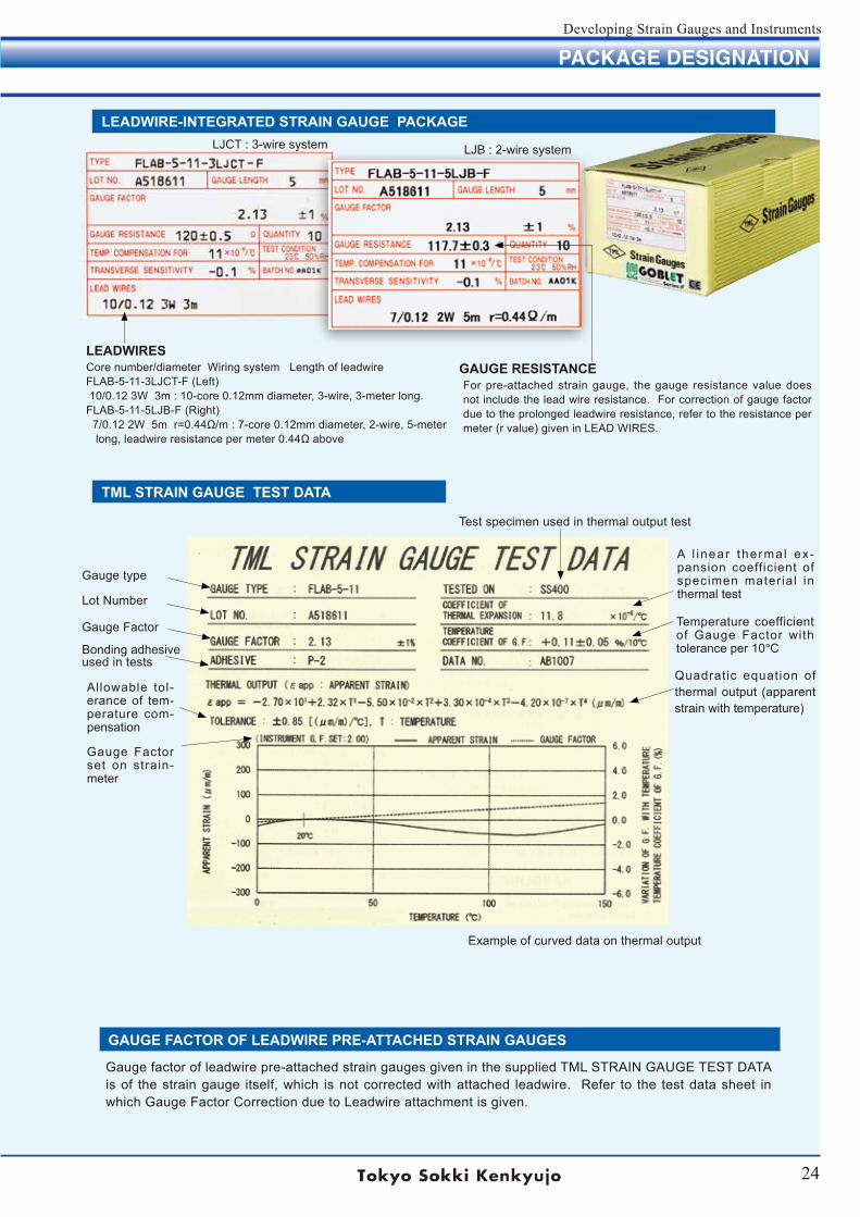
24
Developing Strain Gauges and Instruments
PACKAGE DESIGNATION
LEADWIRE-INTEGRATED STRAIN GAUGE PACKAGE
TML STRAIN GAUGE TEST DATA
Thermal output
Test specimen used in thermal output test
A l inear thermal ex-pansion coefficient of specimen material in thermal test
Temperature coefficient of Gauge Factor with tolerance per 10°C
Quadratic equation of thermal output (apparent strain with temperature)
Gauge type
Lot Number
Gauge Factor
Bonding adhesive used in tests
Allowable tol-erance of tem-perature com-pensation
Gauge Factor set on strain-meter
Example of curved data on thermal output
GAUGE FACTOR OF LEADWIRE PRE-ATTACHED STRAIN GAUGES
Gauge factor of leadwire pre-attached strain gauges given in the supplied TML STRAIN GAUGE TEST DATA is of the strain gauge itself, which is not corrected with attached leadwire. Refer to the test data sheet in which Gauge Factor Correction due to Leadwire attachment is given.
LEADWIRESCore number/diameter Wiring system Length of leadwireFLAB-5-11-3LJCT-F (Left) 10/0.12 3W 3m : 10-core 0.12mm diameter, 3-wire, 3-meter long.FLAB-5-11-5LJB-F (Right) 7/0.12 2W 5m r=0.44Ω/m : 7-core 0.12mm diameter, 2-wire, 5-meter long, leadwire resistance per meter 0.44Ω above
GAUGE RESISTANCEFor pre-attached strain gauge, the gauge resistance value does not include the lead wire resistance. For correction of gauge factor due to the prolonged leadwire resistance, refer to the resistance per meter (r value) given in LEAD WIRES.
LJCT : 3-wire system LJB : 2-wire system
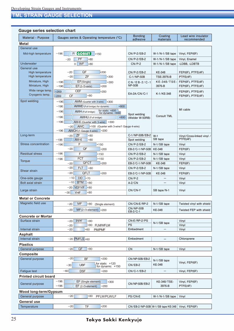
25
Developing Strain Gauges and Instruments
Material - Purpose Gauges series & Operating temperature (°C) Bonding adhesive
Coating materials
Lead wire insulator recommended
MetalGeneral use
Mid-high temperature CN/P-2/EB-2 W-1/N-1/SB tape Vinyl, FEP(6F)
CN/P-2/EB-2 W-1/N-1/SB tape Vinyl, EnamelUnderwater CN/P-2 W-1/N-1/SB tape -LDBB, -LDBTBGeneral use High temperature CN/P-2/EB-2 KE-348 FEP(6F), PTFE(4F) High temperature C-1/NP-50B TSE-3976-B PTFE(4F) Miniature, High Miniature, High
C N / E B -2/ C -1 NP-50B
KE-348/TSE-3976-B
FEP(6F), PTFE(4F)FEP(6F), PTFE(4F)
Wide range temp. Cryogenic temp. EA-2A/CN/C-1 K-1/KE-348
FEP(6F), PTFE(4F)FEP(6F), PTFE(4F)
Spot welding
Spot welding(Welder W-50RB) Consult TML
MI cable
Long-term C-1/NP-50B/EB-2 W-1SB tape
Vinyl/Cross-linked vinyl /PTFE(4F)Spot welding
Stress concentration CN/P-2/EB-2 N-1/SB tape Vinyl
EB-2/C-1/NP-50B KE-348 FEP(6F)Residual stress CN/P-2/EB-2 N-1/SB tape Vinyl
TorqueCN/P-2/EB-2 N-1/SB tape VinylEB-2/C-1/NP-50B KE-348 FEP(6F)
Shear strainCN/P-2/EB-2 N-1/SB tape Vinyl
EB-2/C-1/NP-50B KE-348 FEP(6F)
One-side gauge CN/P-2 ー VinylBolt axial strain A-2/CN ー Vinyl
Large strain CN/CN-Y SB tape/N-1 Vinyl
Metal or ConcreteMagnetic field use CN/CN-E/RP-2 N-1/SB tape Twisted vinyl with shield
CN/NP-50BEB-2/C-1 KE-348 Twisted FEP with shield
Concrete or MortarSurface strain CN-E/RP-2/PS
N-1/SB tapeVinyl
PS VinylInternal strain Embedment ー Vinyl
AsphaltInternal strain Embedment ー Chloroprene
PlasticsGeneral purpose CN N-1/SB tape Vinyl
CompositeGeneral purpose CN/NP-50B/EB-2 N-1/SB tape
KE-348Vinyl, FEP(6F)
CN/EB-2
Fatigue test CN/C-1/EB-2 ー Vinyl, FEP(6F)
Printed circuit board
General purpose CN/NP-50B/EB-2KE-348/TSE-
3976-BVinyl, FEP(6F)PTFE(4F)
Wood long-term/GypsumGeneral purpose PS/CN-E W-1/N-1/SB tape Vinyl
General useTemperature CN/EB-2/NP-50B W-1/SB tape/KE-348 Vinyl, FEP(6F)
GOBLET
Gauge series selection chart
TML STRAIN GAUGE SELECTION
+80
+200
+80
+150
+200
−20
+200−20
+80−20
+60
+150−196
+200
+80ー196+80−20
−20
+150−196
+150−196+200−20
+200−20
+70−10
+80
+80−20
−20
+200
+80
+80−10
−20
ー196
−20
−20
+300
−30
+80−30
+300+200
+200
+80
+300
+800
+300
+200−60
−20 +60
ー196
+80−20
+800
+100+300
+200
−196
0
−20
−20−20
ー196ー196
ー269
+200−20
ー269
ー196
ー196
ー196
ー196
ー196
−196
for static +120 for dynamic +150UBF
TF
PMFLS
PFLW/PLW/LF
EF (2-/3-element)
for static +600 for dynamic +650
EF (Single element)
DSF
BF
GF
PM/PMFFLM/WFLM
P/PF
MF(2-/3-element)
(Single element)MF
YHFYEF/YF
BTMDD
QFLTFLT
QFCTFCTF
QFF
AW-6 ZF
AWCH (1 Gauge 4-wire)AWC
AW-6 (Quarter with 3-wire)
AWHU (Full bridge)
AWH (Full bridge)
AWMD (Full bridge) for dynamic
AWM (Quarter with 3-wire)
CF CEF EF(2-/3-axis)
EF(Single)
ZFQF
WFPF
F/
+80−20
−20 (Quarter with 3-wire/1 Gauge 4-wire)
+80
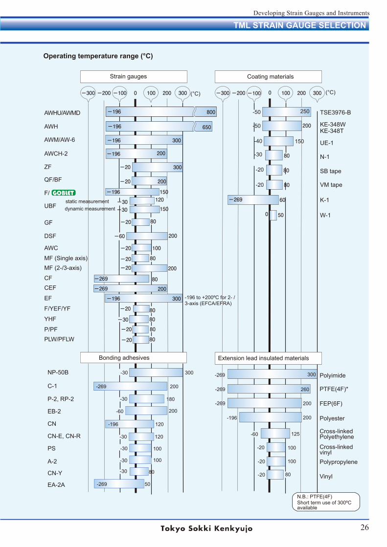
26
Developing Strain Gauges and Instruments
TML STRAIN GAUGE SELECTION
-196 to +200ºC for 2- /3-axis (EFCA/EFRA)
-20 300
-20 80
-100 -100
120
80
50
0
80-20
200
-30
-20 80
-200 100 200 300-300-300 -200 0 100 200 300
-196
-196 300
-196
800
650
-20
80-269
-196 200
200
-30
-20 100
300
80
80
60-269
150
150
80
200-20
-269 200
-196
-60 200
-30 80
-20
-20 80
0
-196
Strain gauges Coating materials
AWHU/AWMD
AWH
AWM/AW-6
AWCH-2
ZF
QF/BF
F/
UBF
GF
DSF
AWC
MF (Single axis)MF (2-/3-axis)
CFCEF
EF
F/YEF/YF
YHF
P/PFPLW/PFLW
TSE3976-B
KE-348WKE-348T
UE-1
N-1
SB tape
VM tape
K-1
W-1
NP-50B
C-1
P-2, RP-2
EB-2
CN
CN-E, CN-R
PS
A-2
CN-Y
EA-2A
Polyimide
PTFE(4F)*
FEP(6F)
Polyester
Cross-linkedPolyethylene
Cross-linkedvinylPolypropylene
Vinyl
Operating temperature range (°C)
static measurementdynamic measurement
Bonding adhesives Extension lead insulated materials
-50
-50
-40
-30
-20
-20
150
N.B.: PTFE(4F)Short term use of 300ºCavailable
(°C) (°C)
-30 300
200-269
-30
-60
-196
-30
-30
-30
-30
-269
180
200
120
120
100
100
50
80
-269
-269
-269
-196
-60
-20
-20
-20
300
260
200
200
125
100
100
80
250
GOBLET
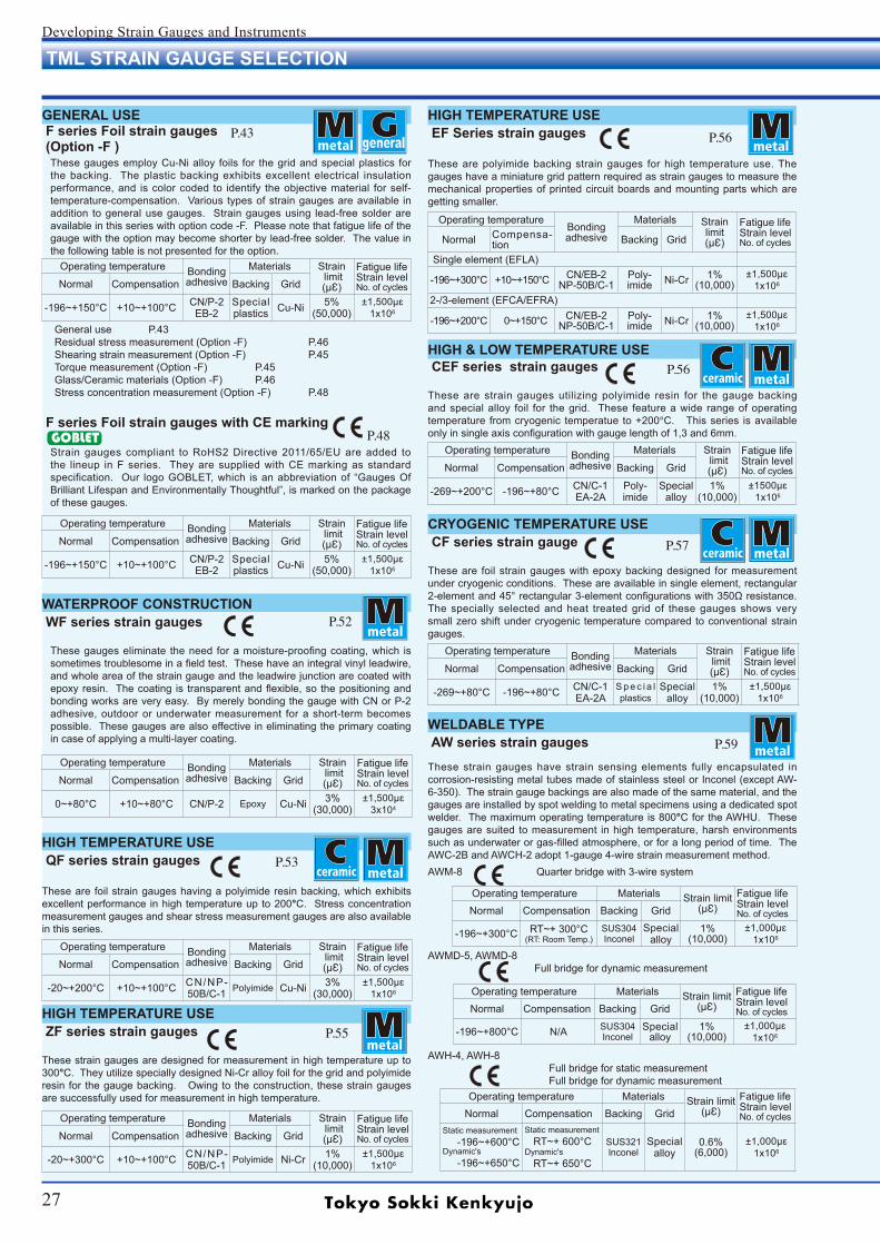
27
Developing Strain Gauges and Instruments
general
Operating temperatureBondingadhesive
Materials Strain limit(µƐ)
Fatigue lifeStrain levelNo. of cyclesNormal Compensa-
tion Backing Grid
Single element (EFLA)
-196~+300°C +10~+150°C CN/EB-2 NP-50B/C-1
Poly-imide Ni-Cr 1%
(10,000)±1,500µɛ
1x10⁶
2-/3-element (EFCA/EFRA)
-196~+200°C 0~+150°C CN/EB-2 NP-50B/C-1
Poly-imide Ni-Cr 1%
(10,000)±1,500µɛ
1x10⁶
Operating temperature Bondingadhesive
Materials Strain limit(µƐ)
Fatigue lifeStrain levelNo. of cyclesNormal Compensation Backing Grid
-196~+150°C +10~+100°C CN/P-2EB-2
Special plastics Cu-Ni 5%
(50,000)±1,500µɛ
1x10⁶
GENERAL USE F series Foil strain gauges (Option -F )
These gauges employ Cu-Ni alloy foils for the grid and special plastics for the backing. The plastic backing exhibits excellent electrical insulation performance, and is color coded to identify the objective material for self-temperature-compensation. Various types of strain gauges are available in addition to general use gauges. Strain gauges using lead-free solder are available in this series with option code -F. Please note that fatigue life of the gauge with the option may become shorter by lead-free solder. The value in the following table is not presented for the option.
General use P.43Residual stress measurement (Option -F) P.46Shearing strain measurement (Option -F) P.45Torque measurement (Option -F) P.45Glass/Ceramic materials (Option -F) P.46Stress concentration measurement (Option -F) P.48
F series Foil strain gauges with CE marking
Strain gauges compliant to RoHS2 Directive 2011/65/EU are added to the lineup in F series. They are supplied with CE marking as standard specification. Our logo GOBLET, which is an abbreviation of “Gauges Of Brilliant Lifespan and Environmentally Thoughtful”, is marked on the package of these gauges.
WATERPROOF CONSTRUCTION WF series strain gauges
These gauges eliminate the need for a moisture-proofing coating, which is sometimes troublesome in a field test. These have an integral vinyl leadwire, and whole area of the strain gauge and the leadwire junction are coated with epoxy resin. The coating is transparent and flexible, so the positioning and bonding works are very easy. By merely bonding the gauge with CN or P-2 adhesive, outdoor or underwater measurement for a short-term becomes possible. These gauges are also effective in eliminating the primary coating in case of applying a multi-layer coating.
HIGH TEMPERATURE USE EF Series strain gauges
These are polyimide backing strain gauges for high temperature use. The gauges have a miniature grid pattern required as strain gauges to measure the mechanical properties of printed circuit boards and mounting parts which are getting smaller.
HIGH & LOW TEMPERATURE USE CEF series strain gauges
These are strain gauges utilizing polyimide resin for the gauge backing and special alloy foil for the grid. These feature a wide range of operating temperature from cryogenic temperatue to +200°C. This series is available only in single axis configuration with gauge length of 1,3 and 6mm.
CRYOGENIC TEMPERATURE USE CF series strain gauge
These are foil strain gauges with epoxy backing designed for measurement under cryogenic conditions. These are available in single element, rectangular 2-element and 45° rectangular 3-element configurations with 350Ω resistance. The specially selected and heat treated grid of these gauges shows very small zero shift under cryogenic temperature compared to conventional strain gauges.
WELDABLE TYPE AW series strain gaugesThese strain gauges have strain sensing elements fully encapsulated in corrosion-resisting metal tubes made of stainless steel or Inconel (except AW-6-350). The strain gauge backings are also made of the same material, and the gauges are installed by spot welding to metal specimens using a dedicated spot welder. The maximum operating temperature is 800°C for the AWHU. These gauges are suited to measurement in high temperature, harsh environments such as underwater or gas-filled atmosphere, or for a long period of time. The AWC-2B and AWCH-2 adopt 1-gauge 4-wire strain measurement method.AWM-8 Quarter bridge with 3-wire system
AWMD-5, AWMD-8 Full bridge for dynamic measurement
HIGH TEMPERATURE USE QF series strain gauges
These are foil strain gauges having a polyimide resin backing, which exhibits excellent performance in high temperature up to 200°C. Stress concentration measurement gauges and shear stress measurement gauges are also available in this series.
P.43
P.52
P.53
P.56
P.59
P.57
P.55
P.56
TML STRAIN GAUGE SELECTION
Operating temperature Bondingadhesive
Materials Strain limit(µƐ)
Fatigue lifeStrain levelNo. of cyclesNormal Compensation Backing Grid
0~+80°C +10~+80°C CN/P-2 Epoxy Cu-Ni 3%(30,000)
±1,500µɛ3x10⁴
Operating temperature Bondingadhesive
Materials Strain limit(µƐ)
Fatigue lifeStrain levelNo. of cyclesNormal Compensation Backing Grid
-20~+200°C +10~+100°C CN/NP-50B/C-1 Polyimide Cu-Ni 3%
(30,000)±1,500µɛ
1x10⁶
Operating temperature Bondingadhesive
Materials Strain limit(µƐ)
Fatigue lifeStrain levelNo. of cyclesNormal Compensation Backing Grid
-20~+300°C +10~+100°C CN/NP-50B/C-1 Polyimide Ni-Cr 1%
(10,000)±1,500µɛ
1x10⁶
Operating temperature Bondingadhesive
Materials Strain limit(µƐ)
Fatigue lifeStrain levelNo. of cyclesNormal Compensation Backing Grid
-269~+200°C -196~+80°C CN/C-1EA-2A
Poly-imide
Special alloy
1%(10,000)
±1500µɛ1x10⁶
Operating temperature Bondingadhesive
Materials Strain limit(µƐ)
Fatigue lifeStrain levelNo. of cyclesNormal Compensation Backing Grid
-269~+80°C -196~+80°C CN/C-1EA-2A
S p e c i a l plastics
Special alloy
1%(10,000)
±1,500µɛ1x10⁶
Operating temperature Materials Strain limit(µƐ)
Fatigue lifeStrain levelNo. of cyclesNormal Compensation Backing Grid
-196~+300°C RT~+ 300°C(RT: Room Temp.)
SUS304Inconel
Special alloy
1%(10,000)
±1,000µɛ1x10⁶
Operating temperature Materials Strain limit(µƐ)
Fatigue lifeStrain levelNo. of cyclesNormal Compensation Backing Grid
-196~+800°C N/A SUS304Inconel
Special alloy
1%(10,000)
±1,000µɛ1x10⁶
Operating temperature Bondingadhesive
Materials Strain limit(µƐ)
Fatigue lifeStrain levelNo. of cyclesNormal Compensation Backing Grid
-196~+150°C +10~+100°C CN/P-2EB-2
Special plastics Cu-Ni 5%
(50,000)±1,500µɛ
1x10⁶
P.48
HIGH TEMPERATURE USE ZF series strain gauges
These strain gauges are designed for measurement in high temperature up to 300°C. They utilize specially designed Ni-Cr alloy foil for the grid and polyimide resin for the gauge backing. Owing to the construction, these strain gauges are successfully used for measurement in high temperature.
AWH-4, AWH-8 Full bridge for static measurement Full bridge for dynamic measurement
Operating temperature Materials Strain limit(µƐ)
Fatigue lifeStrain levelNo. of cyclesNormal Compensation Backing Grid
Static measurement -196~+600°CDynamic's -196~+650°C
Static measurementRT~+ 600°C
Dynamic's RT~+ 650°C
SUS321lnconel
Special alloy
0.6%(6,000)
±1,000µɛ1x10⁶
GOBLET
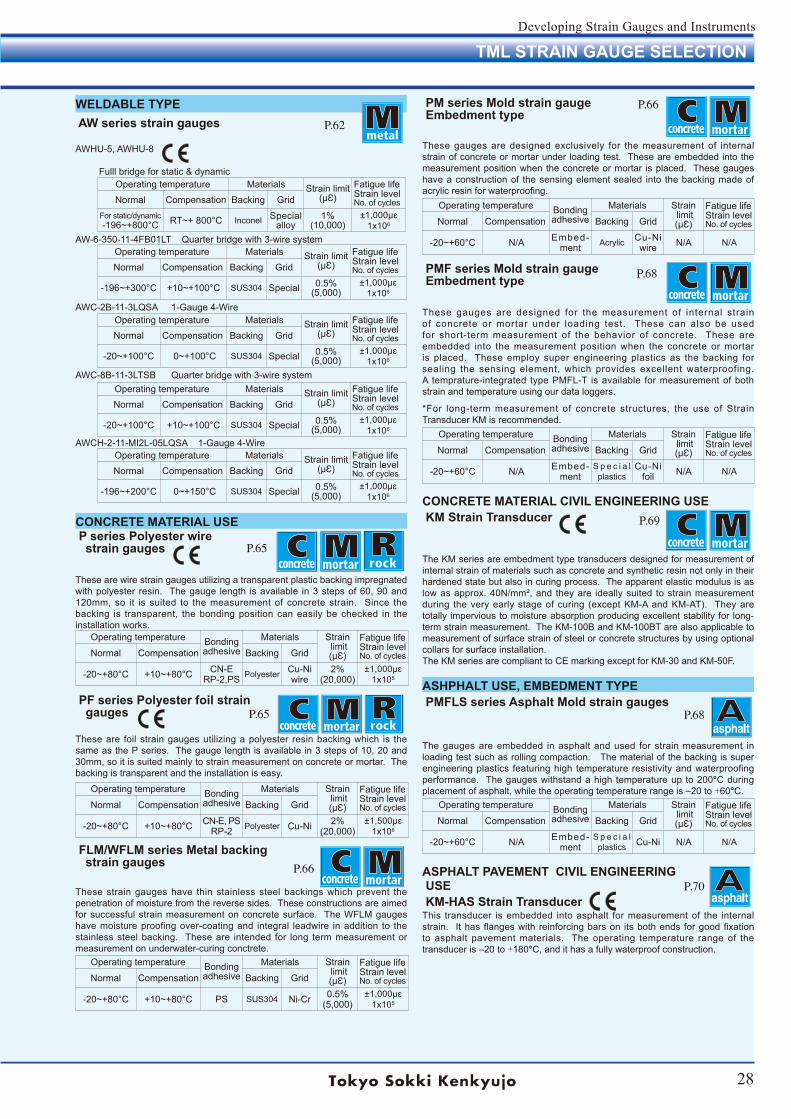
28
Developing Strain Gauges and Instruments
ASHPHALT USE, EMBEDMENT TYPE PMFLS series Asphalt Mold strain gauges
The gauges are embedded in asphalt and used for strain measurement in loading test such as rolling compaction. The material of the backing is super engineering plastics featuring high temperature resistivity and waterproofing performance. The gauges withstand a high temperature up to 200°C during placement of asphalt, while the operating temperature range is ‒20 to +60°C.
ASPHALT PAVEMENT CIVIL ENGINEERING USE KM-HAS Strain TransducerThis transducer is embedded into asphalt for measurement of the internal strain. It has flanges with reinforcing bars on its both ends for good fixation to asphalt pavement materials. The operating temperature range of the transducer is ‒20 to +180°C, and it has a fully waterproof construction.
PM series Mold strain gauge Embedment type
These gauges are designed exclusively for the measurement of internal strain of concrete or mortar under loading test. These are embedded into the measurement position when the concrete or mortar is placed. These gauges have a construction of the sensing element sealed into the backing made of acrylic resin for waterproofing.
PMF series Mold strain gauge Embedment type
These gauges are designed for the measurement of internal strain of concrete or mortar under loading test. These can also be used for short-term measurement of the behavior of concrete. These are embedded into the measurement position when the concrete or mortar is placed. These employ super engineering plastics as the backing for sealing the sensing element, which provides excellent waterproofing. A temprature-integrated type PMFL-T is available for measurement of both strain and temperature using our data loggers. *For long-term measurement of concrete structures, the use of Strain Transducer KM is recommended.
P.65
P.65
P.66
P.66
P.68
CONCRETE MATERIAL CIVIL ENGINEERING USE KM Strain Transducer
The KM series are embedment type transducers designed for measurement of internal strain of materials such as concrete and synthetic resin not only in their hardened state but also in curing process. The apparent elastic modulus is as low as approx. 40N/mm², and they are ideally suited to strain measurement during the very early stage of curing (except KM-A and KM-AT). They are totally impervious to moisture absorption producing excellent stability for long-term strain measurement. The KM-100B and KM-100BT are also applicable to measurement of surface strain of steel or concrete structures by using optional collars for surface installation.The KM series are compliant to CE marking except for KM-30 and KM-50F.
P.69
P.68
P.70
TML STRAIN GAUGE SELECTION
WELDABLE TYPE AW series strain gauges
AWHU-5, AWHU-8 Fulll bridge for static & dynamic
AW-6-350-11-4FB01LT Quarter bridge with 3-wire system
AWC-2B-11-3LQSA 1-Gauge 4-Wire
AWC-8B-11-3LTSB Quarter bridge with 3-wire system
AWCH-2-11-MI2L-05LQSA 1-Gauge 4-Wire
Operating temperature Materials Strain limit(µƐ)
Fatigue lifeStrain levelNo. of cyclesNormal Compensation Backing Grid
For static/dynamic-196~+800°C RT~+ 800°C Inconel Special
alloy1%
(10,000)±1,000µɛ
1x10⁶
Operating temperature Materials Strain limit(µƐ)
Fatigue lifeStrain levelNo. of cyclesNormal Compensation Backing Grid
-196~+300°C +10~+100°C SUS304 Special 0.5%(5,000)
±1,000µɛ1x10⁶
Operating temperature Materials Strain limit(µƐ)
Fatigue lifeStrain levelNo. of cyclesNormal Compensation Backing Grid
-20~+100°C 0~+100°C SUS304 Special 0.5%(5,000)
±1,000µɛ1x10⁶
Operating temperature Materials Strain limit(µƐ)
Fatigue lifeStrain levelNo. of cyclesNormal Compensation Backing Grid
-20~+100°C +10~+100°C SUS304 Special 0.5%(5,000)
±1,000µɛ1x10⁶
Operating temperature Materials Strain limit(µƐ)
Fatigue lifeStrain levelNo. of cyclesNormal Compensation Backing Grid
-196~+200°C 0~+150°C SUS304 Special 0.5%(5,000)
±1,000µɛ1x10⁶
CONCRETE MATERIAL USE P series Polyester wire strain gauges
These are wire strain gauges utilizing a transparent plastic backing impregnated with polyester resin. The gauge length is available in 3 steps of 60, 90 and 120mm, so it is suited to the measurement of concrete strain. Since the backing is transparent, the bonding position can easily be checked in the installation works.
PF series Polyester foil strain gauges
These are foil strain gauges utilizing a polyester resin backing which is the same as the P series. The gauge length is available in 3 steps of 10, 20 and 30mm, so it is suited mainly to strain measurement on concrete or mortar. The backing is transparent and the installation is easy.
FLM/WFLM series Metal backing strain gauges
These strain gauges have thin stainless steel backings which prevent the penetration of moisture from the reverse sides. These constructions are aimed for successful strain measurement on concrete surface. The WFLM gauges have moisture proofing over-coating and integral leadwire in addition to the stainless steel backing. These are intended for long term measurement or measurement on underwater-curing conctrete.
Operating temperature Bondingadhesive
Materials Strain limit(µƐ)
Fatigue lifeStrain levelNo. of cyclesNormal Compensation Backing Grid
-20~+80°C +10~+80°C CN-ERP-2,PS Polyester Cu-Ni
wire2%
(20,000)±1,000µɛ
1x10⁵
Operating temperature Bondingadhesive
Materials Strain limit(µƐ)
Fatigue lifeStrain levelNo. of cyclesNormal Compensation Backing Grid
-20~+80°C +10~+80°C CN-E, PS RP-2 Polyester Cu-Ni 2%
(20,000)±1,500µɛ
1x10⁶
Operating temperature Bondingadhesive
Materials Strain limit(µƐ)
Fatigue lifeStrain levelNo. of cyclesNormal Compensation Backing Grid
-20~+80°C +10~+80°C PS SUS304 Ni-Cr 0.5%(5,000)
±1,000µɛ1x10⁵
Operating temperature Bondingadhesive
Materials Strain limit(µƐ)
Fatigue lifeStrain levelNo. of cyclesNormal Compensation Backing Grid
-20~+60°C N/A Embed-ment Acrylic Cu-Ni
wire N/A N/A
Operating temperature Bondingadhesive
Materials Strain limit(µƐ)
Fatigue lifeStrain levelNo. of cyclesNormal Compensation Backing Grid
-20~+60°C N/A Embed-ment
S p e c i a l plastics
Cu-Ni foil N/A N/A
Operating temperature Bondingadhesive
Materials Strain limit(µƐ)
Fatigue lifeStrain levelNo. of cyclesNormal Compensation Backing Grid
-20~+60°C N/A Embed-ment
S p e c i a l plastics Cu-Ni N/A N/A
P.62
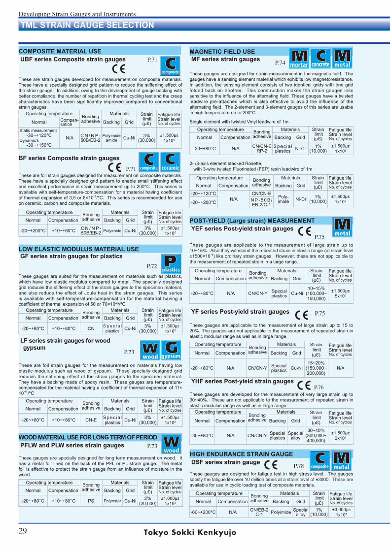
29
Developing Strain Gauges and Instruments
WOOD MATERIAL USE FOR LONG TERM OF PERIOD PFLW and PLW series strain gauges These gauges are specially designed for long term measurement on wood. It has a metal foil lined on the back of the PFL or PL strain gauge. The metal foil is effective to protect the strain gauge from an influence of moisture in the wood.
LOW ELASTIC MODULUS MATERIAL USE GF series strain gauges for plastics
These gauges are suited for the measurement on materials such as plastics, which have low elastic modulus compared to metal. The specially designed grid reduces the stiffening effect of the strain gauges to the specimen material, and also reduce the effect of Joule heat in the strain gauges. This series is available with self-temperature-compensation for the material having a coefficient of thermal expansion of 50 or 70×10-6/°C.
LF series strain gauges for wood gypsum These are foil strain gauges for the measurement on materials having low elastic modulus such as wood or gypsum. These specially designed grid reduces the stiffening effect of the strain gauges to the specimen material. They have a backing made of epoxy resin. These gauges are temperature-compensated for the material having a coefficient of thermal expansion of 11× 10-6 /°C
P.73
P.72
P.73HIGH ENDURANCE STRAIN GAUGE DSF series strain gauge
These gauges are designed for fatigue test in high stress level. The gauges satisfy the fatigue life over 10 million times at a strain level of ±3000. These are available for use in cyclic loading test of composite materials.
P.74
P.76
P.75
P.78
POST-YIELD (Large strain) MEASUREMENT YEF series Post-yield strain gauges These gauges are applicable to the measurement of large strain up to 10~15%. Also they withstand the repeated strain in elastic range (at strain level ±1500×10-6) like ordinary strain gauges. However, these are not applicalble to the measurement of repeated strain in a large range.
P.75
TML STRAIN GAUGE SELECTION
COMPOSITE MATERIAL USE UBF series Composite strain gauges
These are strain gauges developed for measurement on composite materials. These have a specially designed grid pattern to reduce the stiffening effect of the strain gauge. In addition, owing to the development of gauge backing with better compliance, the number of repetition in thermal cycling test and the creep characteristics have been significantly improved compared to conventional strain gauges.
BF series Composite strain gauges
These are foil strain gauges designed for measurement on composite mateirals. These have a specially designed grid pattern to enable small stiffening effect and excellent performance in strain measurement up to 200°C. This series is available with self-temperature-compensation for a material having coefficient of thermal expansion of 3,5 or 8×10⁻⁶/°C. This series is recommended for use on ceramic, carbon and composite materials.
P.71
P.71
Operating temperature Bondingadhesive
Materials Strain limit(µƐ)
Fatigue lifeStrain levelNo. of cyclesNormal Compen-
sation Backing Grid
Static measurement-30~+120°C
Dynamic's-30~+150°C
N/A C N / N P -50B/EB-2
Polyimide amide Cu-Ni 3%
(30,000)±1,500µɛ
1x10⁶
Operating temperature Bondingadhesive
Materials Strain limit(µƐ)
Fatigue lifeStrain levelNo. of cyclesNormal Compensation Backing Grid
-20~+200°C +10~+80°C C N / N P -50B/EB-2 Polyimide Cu-Ni 3%
(30,000)±1,500µɛ
1x10⁶
Operating temperature Bondingadhesive
Materials Strain limit(µƐ)
Fatigue lifeStrain levelNo. of cyclesNormal Compensation Backing Grid
-20~+80°C +10~+80°C CN S p e c i a l plastics Cu-Ni 3%
(30,000)±1,500µɛ
1x10⁶
Operating temperature Bondingadhesive
Materials Strain limit(µƐ)
Fatigue lifeStrain levelNo. of cyclesNormal Compensation Backing Grid
-20~+80°C +10~+80°C CN-E Spec ia l plastics Cu-Ni 3%
(30,000)±1,500µɛ
1x10⁶
Operating temperature Bondingadhesive
Materials Strain limit(µƐ)
Fatigue lifeStrain levelNo. of cyclesNormal Compensation Backing Grid
-20~+80°C +10~+80°C PS Polyester Cu-Ni 2%(20,000)
±1,000µɛ1x10⁵
Operating temperature Bondingadhesive
Materials Strain limit(µƐ)
Fatigue lifeStrain levelNo. of cyclesNormal Compensation Backing Grid
-20~+80°C N/A CN/CN-E RP-2
Spec ia l plastics Ni-Cr 1%
(10,000)±1,500µɛ
1x10⁶
Operating temperature Bondingadhesive
Materials Strain limit(µƐ)
Fatigue lifeStrain levelNo. of cyclesNormal Compensation Backing Grid
-20~+120°CN/A
CN/CN-EPoly-imide Ni-Cr 1%
(10,000)±1,500µɛ
1x10⁶-20~+200°C N P - 5 0 B /EB-2/C-1
Operating temperatureBondingadhesive
Materials Strain limit(µƐ)
Fatigue lifeStrain levelNo. of cyclesNormal Compensation Backing Grid
-20~+80°C N/A CN/CN-Y Specialplastics Cu-Ni
15~20%(150,000~200,000)
N/A
Operating temperature Bondingadhesive
Materials Strain limit(µƐ)
Fatigue lifeStrain levelNo. of cyclesNormal Compensation Backing Grid
-20~+80°C N/A CN/CN-Y Specialplastics Cu-Ni
10~15%(100,000~150,000)
±1,500µɛ5x10⁵
Operating temperatureBondingadhesive
Materials Strain limit(µƐ)
Fatigue lifeStrain levelNo. of cyclesNormal Compensation Backing Grid
-30~+80°C N/A CN/CN-Y Specialplastics
Special alloy
30~40%(300,000~400,000)
±1,500µɛ2x10⁴
Operating temperature Bondingadhesive
Materials Strain limit(µƐ)
Fatigue lifeStrain levelNo. of cyclesNormal Compensation Backing Grid
-60~+200°C N/A CN/EB-2C-1 Polyimide Special
alloy1%
(10,000)±3,000µɛ
1x10⁷
MAGNETIC FIELD USE MF series strain gauges
These gauges are designed for strain measurement in the magnetic field. The gauges have a sensing element material which exhibits low magnetoresistance. In addition, the sensing element consists of two identical grids with one grid folded back on another. This construction makes the strain gauges less sensitive to the influence of the alternating field. These gauges have a twisted leadwire pre-attached which is also effective to avoid the influence of the alternating field. The 2-element and 3-element gauges of this series are usable in high temperature up to 200°C. Single element with twisted Vinyl leadwire of 1m
2- /3-axis element stacked Rosette, with 3-wire twisted Fluorinated (FEP) resin leadwire of 1m
YF series Post-yield strain gauges These gauges are applicable to the measurement of large strain up to 15 to 20%. The gauges are not applicable to the measurement of repeated strain in elastic modulus range as well as in large range.
YHF series Post-yield strain gauges These gauges are developed for the measurement of very large strain up to 30~40%. These are not applicable to the measurement of repeated strain in elastic modulus range as well as in large range.
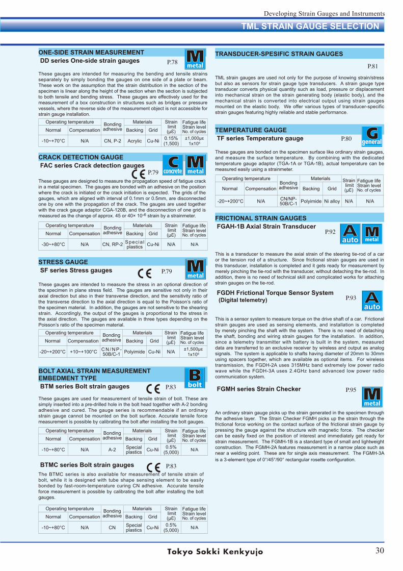
30
Developing Strain Gauges and Instruments
ONE-SIDE STRAIN MEASUREMENT DD series One-side strain gauges
These gauges are intended for measuring the bending and tensile strains separately by simply bonding the gauges on one side of a plate or beam. These work on the assumption that the strain distribution in the section of the specimen is linear along the height of the section when the section is subjected to both tensile and bending stress. These gauges are effectively used for the measurement of a box construction in structures such as bridges or pressure vessels, where the reverse side of the measurement object is not accessible for strain gauge installation.
general
Operating temperatureBondingadhesive
Materials Strain limit(µƐ)
Fatigue lifeStrain levelNo. of cyclesNormal Compensation Backing Grid
-20~+200°C N/A CN/NP-50B/C-1 Polyimide Ni alloy N/A N/A
CRACK DETECTION GAUGE FAC series Crack detection gauges
These gauges are designed to measure the propagation speed of fatigue crack in a metal specimen. The gauges are bonded with an adhesive on the position where the crack is initiated or the crack initiation is expected. The grids of the gauges, which are aligned with interval of 0.1mm or 0.5mm, are disconnected one by one with the propagation of the crack. The gauges are used together with the crack gauge adaptor CGA-120B, and the disconnection of one grid is measured as the change of approx. 45 or 40× 10-6 strain by a strainmeter.
STRESS GAUGE SF series Stress gauges
These gauges are intended to measure the stress in an optional direction of the specimen in plane stress field. The gauges are sensitive not only in their axial direction but also in their transverse direction, and the sensitivity ratio of the transverse direction to the axial direction is equal to the Poisson’s ratio of the specimen material. In addition, the gauges are not sensitive to the shearing strain. Accordingly, the output of the gauges is proportional to the stress in the axial direction. The gauges are available in three types depending on the Poisson’s ratio of the specimen material.
TEMPERATURE GAUGE TF series Temperature gauge
These gauges are bonded on the specimen surface like ordinary strain gauges, and measure the surface temperature. By combining with the dedicated temperature gauge adaptor (TGA-1A or TGA-1B), actual temperature can be measured easily using a strainmeter.
BOLT AXIAL STRAIN MEASUREMENTEMBEDMENT TYPE BTM series Bolt strain gauges
These gauges are used for measurement of tensile strain of bolt. These are simply inserted into a pre-drilled hole in the bolt head together with A-2 bonding adhesive and cured. The gauge series is recommendable if an ordinary strain gauge cannot be mounted on the bolt surface. Accurate tensile force measurement is possible by calibrating the bolt after installing the bolt gauges.
TRANSDUCER-SPESIFIC STRAIN GAUGES
TML strain gauges are used not only for the purpose of knowing strain/stress but also as sensors for strain gauge type transducers. A strain gauge type transducer converts physical quantity such as load, pressure or displacement into mechanical strain on the strain generating body (elastic body), and the mechanical strain is converted into electrical output using strain gauges mounted on the elastic body. We offer various types of transducer-specific strain gauges featuring highly reliable and stable performance.
P.78
P.79
P.79
P.80
P.83
P.81
BTMC series Bolt strain gaugesThe BTMC series is also available for measurement of tensile strain of bolt, while it is designed with tube shape sensing element to be easily bonded by fast-room-temperature curing CN adhesive. Accurate tensile force measurement is possible by calibrating the bolt after installing the bolt gauges.
FRICTIONAL STRAIN GAUGES FGAH-1B Axial Strain Transducer
This is a transducer to measure the axial strain of the steering tie-rod of a car or the tension rod of a structure. Since frictional strain gauges are used in this transducer, installation is completed and it gets ready for measurement by merely pinching the tie-rod with the transducer, without detaching the tie-rod. In addition, there is no need of technical skill and complicated works for attaching strain gauges on the tie-rod.
FGDH Frictional Torque Sensor System (Digital telemetry)
This is a sensor system to measure torque on the drive shaft of a car. Frictional strain gauges are used as sensing elements, and installation is completed by merely pinching the shaft with the system. There is no need of detaching the shaft, bonding and wiring strain gauges for the installation. In addition, since a telemetry transmitter with battery is built in the system, measured data are transferred to an exclusive receiver by wireless and output as analog signals. The system is applicable to shafts having diameter of 20mm to 30mm using spacers together, which are available as optional items. For wireless transmission, the FGDH-2A uses 315MHz band extremely low power radio wave while the FGDH-3A uses 2.4GHz band advanced low power radio communication system.
FGMH series Strain Checker
An ordinary strain gauge picks up the strain generated in the specimen through the adhesive layer. The Strain Checker FGMH picks up the strain through the frictional force working on the contact surface of the frictional strain gauge by pressing the gauge against the structure with magnetic force. The checker can be easily fixed on the position of interest and immediately get ready for strain measurement. The FGMH-1B is a standard type of small and lightweight construction. The FGMH-2A features measurement in a narrow place such as near a welding point. These are for single axis measurement. The FGMH-3A is a 3-element type of 0°/45°/90° rectangular rosette configuration.
auto
auto
P.95
P.92
P.93
P.83
TML STRAIN GAUGE SELECTION
Operating temperature Bondingadhesive
Materials Strain limit(µƐ)
Fatigue lifeStrain levelNo. of cyclesNormal Compensation Backing Grid
-10~+70°C N/A CN, P-2 Acrylic Cu-Ni 0.15%(1,500)
±1,000µɛ1x10⁵
Operating temperature Bondingadhesive
Materials Strain limit(µƐ)
Fatigue lifeStrain levelNo. of cyclesNormal Compensation Backing Grid
-30~+80°C N/A CN, RP-2 Spec ia l plastics Cu-Ni N/A N/A
Operating temperature Bondingadhesive
Materials Strain limit(µƐ)
Fatigue lifeStrain levelNo. of cyclesNormal Compensation Backing Grid
-20~+200°C +10~+100°C C N / N P -50B/C-1 Polyimide Cu-Ni N/A ±1,500µɛ
1x10⁶
Operating temperature Bondingadhesive
Materials Strain limit(µƐ)
Fatigue lifeStrain levelNo. of cyclesNormal Compensation Backing Grid
-10~+80°C N/A A-2 Specialplastics Cu-Ni 0.5%
(5,000) N/A
Operating temperature Bondingadhesive
Materials Strain limit(µƐ)
Fatigue lifeStrain levelNo. of cyclesNormal Compensation Backing Grid
-10~+80°C N/A CN Specialplastics Cu-Ni 0.5%
(5,000) N/A
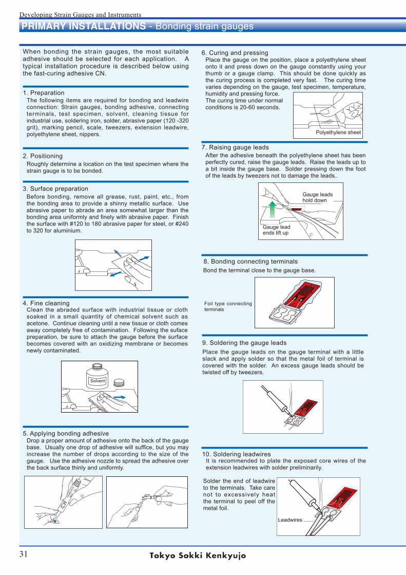
31
Developing Strain Gauges and Instruments
PRIMARY INSTALLATIONS - Bonding strain gauges
When bonding the strain gauges, the most suitable adhesive should be selected for each application. A typical installation procedure is described below using the fast-curing adhesive CN.
1. PreparationThe following items are required for bonding and leadwire connection: Strain gauges, bonding adhesive, connecting terminals, test specimen, solvent, cleaning tissue for industrial use, soldering iron, solder, abrasive paper (120 -320 grit), marking pencil, scale, tweezers, extension leadwire, polyethylene sheet, nippers.
2. PositioningRoughly determine a location on the test specimen where the strain gauge is to be bonded.
3. Surface preparationBefore bonding, remove all grease, rust, paint, etc., from the bonding area to provide a shinny metallic surface. Use abrasive paper to abrade an area somewhat larger than the bonding area uniformly and finely with abrasive paper. Finish the surface with #120 to 180 abrasive paper for steel, or #240 to 320 for aluminium.
4. Fine cleaningClean the abraded surface with industrial tissue or cloth soaked in a small quantity of chemical solvent such as acetone. Continue cleaning until a new tissue or cloth comes away completely free of contamination. Following the suface preparation, be sure to attach the gauge before the surface becomes covered with an oxidizing membrane or becomes newly contaminated.
5. Applying bonding adhesiveDrop a proper amount of adhesive onto the back of the gauge base. Usually one drop of adhesive will suffice, but you may increase the number of drops according to the size of the gauge. Use the adhesive nozzle to spread the adhesive over the back surface thinly and uniformly.
ADHESIVENET 2gCYA
7. Raising gauge leadsAfter the adhesive beneath the polyethylene sheet has been perfectly cured, raise the gauge leads. Raise the leads up to a bit inside the gauge base. Solder pressing down the foot of the leads by tweezers not to damage the leads..
8. Bonding connecting terminals
Foil type connecting terminals
9. Soldering the gauge leads
10. Soldering leadwiresIt is recommended to plate the exposed core wires of the extension leadwires with solder preliminarily.
6. Curing and pressingPlace the gauge on the position, place a polyethylene sheet onto it and press down on the gauge constantly using your thumb or a gauge clamp. This should be done quickly as the curing process is completed very fast. The curing time varies depending on the gauge, test specimen, temperature, humidity and pressing force. The curing time under normal conditions is 20-60 seconds.
Bond the terminal close to the gauge base.
Place the gauge leads on the gauge terminal with a little slack and apply solder so that the metal foil of terminal is covered with the solder. An excess gauge leads should be twisted off by tweezers.
Solder the end of leadwire to the terminals. Take care not to excessively heat the terminal to peel off the metal foil.
Gauge leads hold down
Gauge lead ends lift up
Polyethylene sheet
Leadwires
Solvent
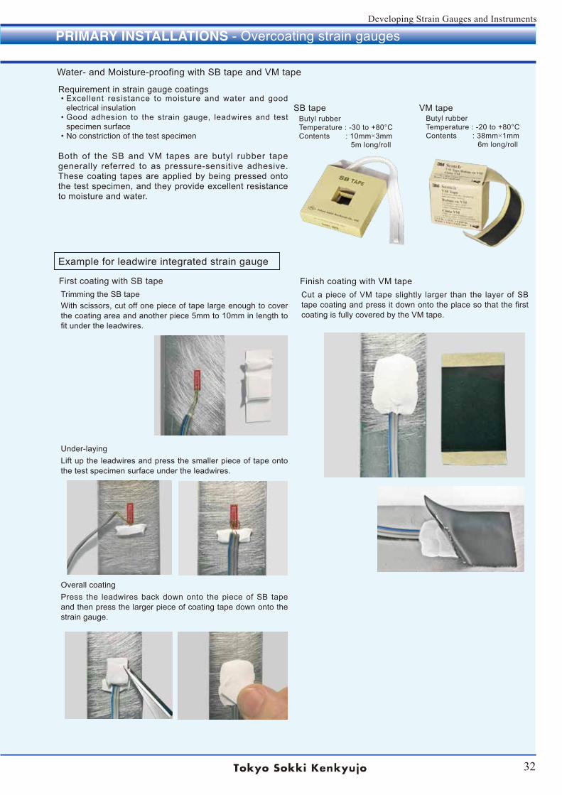
32
Developing Strain Gauges and Instruments
PRIMARY INSTALLATIONS - Overcoating strain gauges
Water- and Moisture-proofing with SB tape and VM tape
First coating with SB tapeTrimming the SB tapeWith scissors, cut off one piece of tape large enough to cover the coating area and another piece 5mm to 10mm in length to fit under the leadwires.
Both of the SB and VM tapes are butyl rubber tape generally referred to as pressure-sensitive adhesive. These coating tapes are applied by being pressed onto the test specimen, and they provide excellent resistance to moisture and water.
Under-layingLift up the leadwires and press the smaller piece of tape onto the test specimen surface under the leadwires.
Overall coatingPress the leadwires back down onto the piece of SB tape and then press the larger piece of coating tape down onto the strain gauge.
Finish coating with VM tapeCut a piece of VM tape slightly larger than the layer of SB tape coating and press it down onto the place so that the first coating is fully covered by the VM tape.
Requirement in strain gauge coatings• Excellent resistance to moisture and water and good
electrical insulation• Good adhesion to the strain gauge, leadwires and test
specimen surface• No constriction of the test specimen
SB tape VM tapeButyl rubberTemperature : -30 to +80°CContents : 10mm×3mm 5m long/roll
Butyl rubberTemperature : -20 to +80°CContents : 38mm×1mm 6m long/roll
Example for leadwire integrated strain gauge
33
Developing Strain Gauges and Instruments
Strain gauges are connected to strain measuring instruments using extension leadwires. We offer various types of leadwires to be selected depending on the usage conditions. In addition, most of TML strain gauges are available with extension leadwires preattached at our factory. Those leadwire-integrated strain gauges greatly save the leadwire connection works during the strain gauge installation. Please feel free to contact TML or local representative for the extension leadwires and the leadwire-integrated strain gauges.Standard leadwire length for leadwire-integrated strain gaugesStandard length of our integral leadwires is 1m, 3m and 5m except enamel leadwires. The standard length of enamel leadwires are 0.3m, 0.5m and 1m. Other lengths than the standard length may be available on request. The enamel leadwires are not available in a length more than 1m.
·OPTION -F Leadwire with CE markingLeadwire with CE marking (compliant to RoHS2 Directive)Identification code “-F” is appended to the type number of the leadwire.
Type number of leadwires(Option code -F for CE marking)
Core/Diameter(cross section)
Applicabletemperature
Total resist-ance of lead
wireOuter insulated dimensions
Length per roll Colors
0.08mm2 paralleled vinyl lead wire LJB/LJB-F
7/0.12(0.08mm2) -20 ~+80°C 0.44Ω/m
1.1 x 2.2mm200m
for Red
400mfor others
Red, White, Green, Black, Yellow Blue, Red-White
0.08mm2 3-wire paralleled vinyl leadwire LJBT/LJBT-F
1.1 x 3.3mmWhite wire and whichever color Blue, Orange, Red, Green, Black or Yellow stripe is selectable.(*)
0.08mm2 twisted vinyl leadwire LJA7/0.12
(0.08mm2) -20 ~+80°C 0.44Ω/mφ 1.6mm
-Red, Green, Yellow
0.08mm2 3-wire twisted vinyl leadwire LJATφ 1.9mm Red-Green-Ye l low, Red-
Green-Blue, Red-Green-White
0.11mm2 paralleled vinyl lead wire LJC/LJC-F
10/0.12(0.11mm2) -20 ~+80°C 0.32Ω/m
1.4 x 2.8mm 200m Grey
0.11mm2 3-wire paralleled vinyl leadwire LJCT/LJCT-F 1.4 x 4.2mm 100m Grey, One wire with Blue
stripe (*)
0.3mm2 paralleled vinyl leadwire LJD
12/0.8(0.3mm2) -20 ~+80°C 0.12Ω/m
1.9 x 3.8mm 200m Grey
0.3mm2 3-wire paralleled vinyl leadwire LJDT1.9 x 5.7mm 100m White, One wire with Red
stripe (*)
0.5mm2 paralleled vinyl leadwire LJG
20/0.8(0.5mm2) -20 ~+80°C 0.07Ω/m
2.5 x 5.0mm100m
Grey
0.5mm2 3-wire paralleled vinyl leadwire LJGT2.1 x 6.3mm White, One wire with Blue
stripe (*)
0.02mm2 twisted vinyl leadwire LH
5/0.07(0.02mm2) -20 ~+100°C 1.8 Ω/m
φ 0.8mm-
Red, Green, White
0.02mm2 3-wire twisted vinyl leadwire LHTφ 1.0mm Red-Green-White
3.2mm-dia. 2-core shielded vinyl leadwire LS 7/0.12 (0.08mm2) -20 ~+80°C 0.44Ω/m φ 3.2mm 200m Outer : Red, White or Green
Core wire : Red-Black-White
3mm-dia. 3-core shielded vinyl leadwire LTSA7/0.12
(0.08mm2) -20 ~+80°C 0.1 Ω/m φ 3mm 200mOuter insulated: BlackCore wire insulated: Red-Black-White
5mm-dia. 3-core shielded vinyl leadwire LTSB7/0.26
(0.3mm2) -20 ~+80°C 0.1Ω/m φ 5mm 200m White, One wire with Red, Blue or Black stripe (*)
0.08mm2 polypropyrene 4-wire paralleled leadwire LQM/LQM-F 7/0.12
(0.08mm2) -20 ~+100°C 0.44Ω/m 0.9 x 4.0mm 200m White, One wire with Red stripe (*)
N.B.: * Stripe is for distinction of independent wire in quarter bridge.
¶ Vinyl leadwires Vinyl leadwires are widely used as strain gauge leadwires, and are available in a variety of types. Because the vinyl insulation can be colored, these wires allow color-coding for rosette gauges. Stranded core wires are flexible and easy to handle, and allow easy wire connection and terminal attachment.·Small diameter vinyl wires (Code to order -LH, -LHT)These leadwires feature a thin vinyl insulated materials and small diameter core wires to achieve an outside diameter of 0.4mm. They are used for wiring in tight spaces. The stranded wires are flexible and minimize breakage due to repeated bending.·Shielded vinyl wires (Code to order -LTSA, -LTSB)These are 3-core wires with shield made of aluminium foil or braided copper wire. The outer insulation is made of vinyl. These leadwires offer a noise shielding function.
STRAIN GAUGE EXTENSION LEADWIRES
Leadwire selection
34
Developing Strain Gauges and Instruments
34
Developing Strain Gauges and Instruments
¶ Enamel leadwires Enamel leadwires have a single core insulated with a resin. Heat resistance and handling methods vary depending on resin. Because the wire mass and diameter are small, enamel leadwires are used for strain measurement of rotating specimens and/or measurement of multiple points located in close proximity. Since the enamel leadwire contains one core covered with a thin resin, it must be handled with care.·Polyurethane leadwires
Polyurethane leadwires allow easy post-processing because the resin can be removed with a soldering iron. The resin is not strong, therefore, polyurethane wires must be handled with special care.
·Polyester leadwires Polyester leadwires are harder than polyurethane wires, it cannot be removed with a soldering iron.
·Polyimide leadwires Polyimide leadwires are harder than the polyester wire. A soldering iron cannot be used for post-processing.)
Leadwire type Core/Diameter Applicable temperature
Total resistance of leadwire
Outer insulated dimensions Colors
0.14mm-dia. Polyurethane leadwire LP/LP-F 1/0.14-10 ~+120°C
2.5Ω/m φ 0.16mmRed, Brown, Green
0.18mm-dia. Polyurethane leadwire LP/LP-F 1/0.18 1.5Ω/m φ 0.20mm
0.14mm-dia. Polyester leadwire LU/LU-F 1/0.14-196 ~+200°C
2.5Ω/m φ 0.16mmBrown
0.18mm-dia. Polyester leadwire LU/LU-F 1/0.18 1.5Ω/m φ 0.20mm
0.14mm-dia. Polyimide leadwire LE/LE-F 1/0.14-269 ~+300°C
2.5Ω/m φ 0.16mmBrown
0.18mm-dia. Polyimide leadwire LE/LE-F 1/0.18 1.5Ω/m φ 0.20mm
¶ Cross-linked Vinyl leadwiresThe cross-linked vinyl insulation provides improved resistance against environmental elements. It is often used for underwater measurement in ordinary temperature.
¶ Cross-linked Polyethylene leadwires The cross-linked polyethylene leadwire offers higher durability than the cross-linked vinyl leadwire. Cross-linked polyethylene leadwires can be used in steam, warm water and concrete with virtually no insulation degradation.
Leadwire type Core/Diameter (Cross section)
Applicabletemperature
Total resistance of leadwire
Outer insulated dimensions
Lengthper roll Colors
2-wire twisted cross-linked vinyl leadwire LJRA7/0.16
(0.14mm2)-20 ~+100°C
0.24Ω/m φ 3.0mm White
3-wire twisted cross-linked vinyl leadwire LJRTA7/0.127
(0.09mm2) 0.4Ω/m φ 2.0mm 200m Red-Green-Black
3-wire twisted cross-linked polyethylene leadwire LJQTA 7/0.127
(0.09mm2) -65 ~+125°C 0.4Ω/m φ 2.0mmRed-Yellow-BlackRed-Yellow-BlueRed-Yellow-White
¶ Special leadwire for temperature-integrated gauge Special leadwire for temperature-integrated gauge consists of 2-core copper and 1-core constantan. To extend this wire, the exclusive leadwire should be applied properly.
Leadwire type Core/Diameter(Cross section)
Applicable temperature
Total resistance of leadwire
Outer insulated dimensions
Length per roll Colors
Temperature-integrated 3-wire paralleled vinyl leadiwre TLJBT/TLJBT-F 7/0.12
(0.08mm2) -20 ~+80°C 0.44Ω/m 1.2x3.6mm Red-White-Blue
Temperature-integrated 4-wire paralleled vinyl leadwire TLQ 7/0.12
(0.08mm2) -20 ~+80°C 0.44Ω/m 1.2x4.8mm Red-Green-White-Blue
Temperature-integrated 3-wire twisted fluorinated resin (FEP) leadwire 6FB_TLT 1/0.2 -269 ~+200°C 1.05Ω/m φ 1.1mm Red-White-Blue
Type number of leadwires(Option code -F for CE marking)
Core/Diameter(cross section)
Applicabletemperature
Total resist-ance of lead
wireOuter insulated dimensions
L e n g t h per roll Colors
0.08mm2 vinyl 4-wire paralleled leadwire LBQM/LBQM-F 7/0.12
(0.08mm2) -20 ~+80°C 0.44Ω/m 1.0 x 4.0mm 200m
3-wire paralleled special vinyl leadwire LXT/ LXT-F 7/0.12
(0.08mm2) -20 ~+150°C 0.44Ω/m 0.9 x 2.7mm 200m Red-Black-White
STRAIN GAUGE EXTENSION LEADWIRES
35
Developing Strain Gauges and Instruments
35
Developing Strain Gauges and Instruments
Leadwire
ConstructionDimension Code to
ordera b
2-wire paralleled
7/0.12 1.1 2.2 -LJB/-LJB-F10/0.12 1.4 2.8 -LJC/-LJC-F
2-wiretwisted
7/0.12 0.8 - -LJA5/0.07 0.4 - -LH
3-wireparalleled
7/0.12 1.1 3.3 -LJBT/-LJBT-F10/0.12 1.4 4.2 -LJCT/-LJCT-F
3-wiretwisted 7/0.12 0.8 -LJAT
Most TML strain gauges are available with extension leadwires pre-attached for customer convenience. We have several methods for connecting leadwires to be chosen depending on conditions such as the type of strain gauge and leadwire, measurement environments and so on.
Different joints·Integral type
A vinyl leadwire is jointed to polyimide insulaed gauge leads of a strain gauge. The solder joints are covered with the vinyl insulation of the leadwire. This is our standard method of integral leadwire attachment.
·Heat-shrinkable tubingA soldered joint between gauge leads and leadwire is protected with a heat shrinkable tube. The heat shrinkable tubes are available in three ratings of temperature among 80°C, 200°C and 260°C.
·Connecting terminals joint typeGauge leads and leadwires are jointed using foil shape connecting terminals. Measurement in high temperature is possible by using a high temperature solder with melting point of 300°C or more for the joint.
·Insulation film typeA soldered joint between gauge leads and leadwires is covered with an insulation film of glass cloth base. The film is resistive to heat up to 300°C, so this method is suited to measurement in high temperature.
·Direct typeA vinyl leadwire is jointed directly to gauge leads, which are made of nickel plated copper. The solder joints are covered with vinyl insulation of a leadwire up to the end of the gauge base.
b
a
Polyimide insulation
Gauge lead length approx. 15mm
Integral type
2-wire
3-wire
Cross section Vinyl leadwire
Vinyl leadwire
¶ Fluorinated resin leadwire With a fluorinated resin leadwires, these leadwires can be used in a wide range of temperature from extremely low to high temperatures. Fluorinated resin resists most chemicals. A surface treatment (tetra-etching) is not required by 6FAS_LT(-F).
Leadwire type Core/Diameter (Cross section)
Applicabletemperature
Total resistance of leadwire
Outer insulated dimensions
Length per roll*1
Suffix code of leadwire Colors
3-wire twisted fluorinated resin (FEP) insulated leadwire 6FA_LT/6FA_LT-F 7/0.18
(0.18mm2) -269 ~+200°C 0.2Ω/m φ 2.0mm 100m -6FA_LT*2 Red-Green-Blue
3-wire twisted fluorinated resin (FEP) insulated leadwire 6FAS_LT/6FAS_LT-F 7/0.18
(0.18mm2) -269 ~+200°C 0.2Ω/m φ 2.0mm 100m -6FAS_LT Red-Green-Blue
3-wire twisted fluorinated resin (FEP) insulated leadwire 6FB_LT/6FB_LT-F 1/0.2
(0.09mm2) -269 ~+200°C 1.2Ω/m φ 1.1mm - -6FB_LT Red-Green-Blue
3-wire twisted fluorinated resin (FEP) insulated leadwire 6FC_LT/6FC_LT-F 7/0.08
(0.04mm2) -269 ~+200°C 1.1Ω/m φ 1.1mm - -6FC_LT Red-Black-White
3-wire twisted fluorinated resin (FEP) insulated leadwire 6FD_LTS/6FD_LTS-F 7/0.08
(0.04mm2) -269 ~+200°C 1.1Ω/m φ 1.1mm - -6FD_LTS Red-Black-White
3-wire twisted f luorinated resin (PTFE) insulated leadwire 4FA_LT/4FA_LT-F 7/0.16
(0.14mm2)-269 ~+260°C*3 0.24Ω/m φ 1.9mm 100m -4FA_LT*4 Red-Grey-White
3-wire twisted f luorinated resin (PTFE) insulated leadwire 4FB_LT/4FB_LT-F 1/0.2 -269 ~+260°C 1.05Ω/m φ 1.1mm - -4FB_LT*4 Red-Black-White
N.B.: *1 : Leadwires are sold by one roll each *2 : _LT is filled with required length *3 : PTFE leadwire is available in 300ºC for short- term use. *4 : Suffix code LT (CT) is provided with connecting terminal joint, and another LT(TA) with insulation film
HOW ARE INTEGRAL LEADWIRES JOINTED
STRAIN GAUGE EXTENSION LEADWIRES
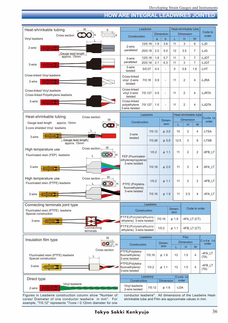
36
Developing Strain Gauges and Instruments
Leadwire Heat-shrinkable tubeCode to
orderConstruction Dimen-sion
DimensionL H W
3-wire twisted
7/0.12 φ 3.0 10 2 4 -LTSA
7/0.26 φ 5.0 12.5 3 6 -LTSB
FEP (Fluorinated-ethylenepropylene)
3-wire twisted
1/0.2 φ 1.1 11 2 2 -6FB_LT
7/0.18 φ 2.0 11 3 4 -6FA_LT
PTFE (Polytetra- fluoroethylene)3-wire twisted
1/0.2 φ 1.1 11 2 2 -4FB_LT
7/0.16 φ 1.9 11 2.5 4 -4FA_LT
Cross section
LeadwireCode to order
Construction Dimen-sion
PTFE(Polytetrafluoro-ethylene) 3-wire twisted 7/0.16 φ 1.9 -4FA_LT (CT)
PTFE(Polytetrafluoro-ethylene) 3-wire twisted 1/0.2 φ 1.1 -4FB_LT (CT)
Leadwire Code to orderConstruction Dimension
Vinyl leadwire2-wire twisted 7/0.12 φ 1.6 -LDA
Leadwire FilmC o d e t o
orderConstruction Dimen-sion
DimensionL H W
PTFE(Polytetra- fluoroethylene)3-wire twisted
7/0.16 φ 1.9 13 1.5 4 -4FA_LT(TA)
PTFE(Polytetra- fluoroethylene)3-wire twisted
1/0.2 φ 1.1 13 1.5 4 -4FB_LT(TA)
L
L
Leadwire Heat-shrinkable tubeCode to
orderConstructionDimension Dimension
a b L H W
2-wire paralleled
12/0.18 1.9 3.8 11 3 6 -LJD
20/0.18 2.5 5.0 12 3.5 7 -LJG
3-wireparalleled
12/0.18 1.9 5.7 11 3 7 -LJDT20/0.18 2.1 6.3 11 3 7 -LJGT
3-wire twisted 5/0.07 0.4 - 5 0.8 1.6 -LHT
Cross-linkedvinyl 2-wire
twisted7/0.16 0.9 - 11 2 4 -LJRA
Cross-linkedvinyl 3-wire
twisted7/0.127 0.9 - 11 2 4 -LJRTA
Cross-linkedpolyethylene3-wire twisted
7/0.127 1.0 - 11 2 4 -LJQTA
Heat-shrinkable tubing
Gauge lead length approx. 15mm
b
a
W
H
LVinyl leadwire
2-wire
3-wire
2-wire
3-wire
Cross-linked Vinyl leadwire
Cross-linked Vinyl leadwireCross-linked Polyethylene leadwire
Cross section
Heat-shrinkable tubing
Gauge lead length approx. 15mm
Gauge lead length approx. 15mm
3-core shielded Vinyl leadwire
3-wire
3-wire
3-wire
High temperature use Fluorinated resin (FEP) leadwire
High temperature use Fluorinated resin (PTFE) leadwire
W
H
W
H
Cross section
Cross section
Connecting terminals joint type Fluorinated resin (PTFE) leadwire Special construction
3-wire
Insulation film type
Direct type
W
H
Cross section
L Fluorinated resin (PTFE) leadwire Special construction
3-wire
2-wireVinyl leadwire
Figures in Leadwire construction column show "Number of cores/ Diameter of one conductor leadwire in mm". For example, "7/0.12" represents "7core / 0.12mm diameter for one
Connecting terminals
L
conductor leadwire". All dimensions of the Leadwire Heat-shrinkable tube and Film are approximate values in mm.
H
W
HOW ARE INTEGRAL LEADWIRES JOINTED
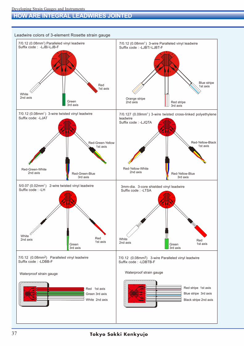
37
Developing Strain Gauges and Instruments
HOW ARE INTEGRAL LEADWIRES JOINTED
7/0.12 (0.08mm2) Paralleled vinyl leadwire Suffix code : -LJB/-LJB-F
7/0.12 (0.08mm2 ) 3-wire Paralleled vinyl leadwire Suffix code : -LJBT/-LJBT-F
Red 1st axis
Green 3rd axis
White 2nd axis Orange stripe
2nd axis Red stripe 3rd axis
Blue stripe 1st axis
Red-Green-White 2nd axis Red-Green-Blue
3rd axis
Red-Green-Yellow 1st axis
7/0.12 (0.08mm2 ) 3-wire twisted vinyl leadwire Suffix code: -LJAT
Red-Yellow-White 2nd axis Red-Yellow-Blue
3rd axis
Red-Yellow-Black1st axis
7/0.127 (0.09mm2 ) 3-wire twisted cross-linked polyethylene leadwire Suffix code : -LJQTA
5/0.07 (0.02mm2 ) 2-wire twisted vinyl leadwire Suffix code : -LH
Red 1st axis
Green 3rd axis
White 2nd axis Red
1st axisGreen 3rd axis
White 2nd axis
3mm-dia. 3-core shielded vinyl leadwire Suffix code : -LTSA
Red stripe 1st axis
Blue stripe 3rd axis
Black stripe 2nd axis
7/0.12 (0.08mm2) 3-wire Paralleled vinyl leadwire Suffix code : -LDBTB-F
7/0.12 (0.08mm2) Paralleled vinyl leadwire Suffix code : -LDBB-F
Red 1st axisGreen 3rd axis
White 2nd axis
Leadwire colors of 3-element Rosette strain gauge
Waterproof strain gauge Waterproof strain gauge
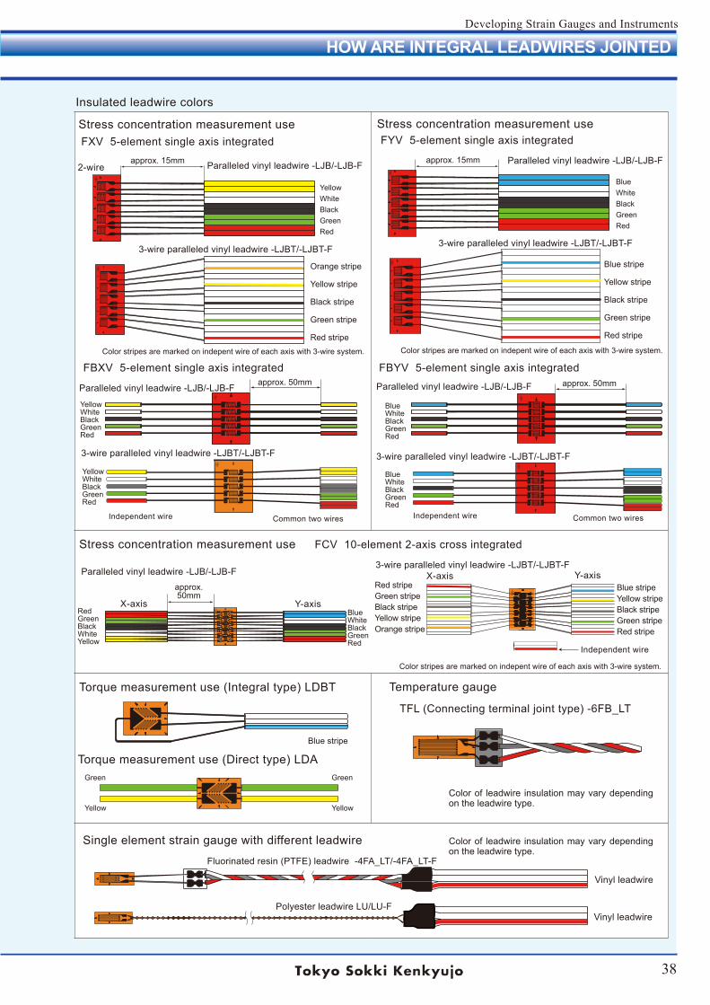
38
Developing Strain Gauges and Instruments
Paralleled vinyl leadwire -LJB/-LJB-F3-wire paralleled vinyl leadwire -LJBT/-LJBT-F
3-wire paralleled vinyl leadwire -LJBT/-LJBT-F3-wire paralleled vinyl leadwire -LJBT/-LJBT-F
Paralleled vinyl leadwire -LJB/-LJB-FParalleled vinyl leadwire -LJB/-LJB-F
Paralleled vinyl leadwire -LJB/-LJB-F Paralleled vinyl leadwire -LJB/-LJB-F
3-wire paralleled vinyl leadwire -LJBT/-LJBT-F3-wire paralleled vinyl leadwire -LJBT/-LJBT-F
HOW ARE INTEGRAL LEADWIRES JOINTED
}}}}}
Stress concentration measurement use
approx. 15mm approx. 15mm
approx. 50mm approx. 50mm
FXV 5-element single axis integrated
FBXV 5-element single axis integrated
YellowWhiteBlackGreenRed
Orange stripe
Yellow stripe
Black stripe
Green stripe
Red stripe
YellowWhiteBlackGreenRed
2-wire
YellowWhiteBlackGreenRed
BlueWhiteBlackGreenRed
Blue stripe
Yellow stripe
Black stripe
Green stripe
Red stripe
BlueWhiteBlackGreenRed
BlueWhiteBlackGreenRed
FBYV 5-element single axis integrated
FYV 5-element single axis integrated
Stress concentration measurement use FCV 10-element 2-axis cross integrated
approx. 50mm
RedGreenBlackWhiteYellow
BlueWhiteBlackGreenRed
X-axis Y-axis
X-axis Y-axisBlue stripeYellow stripeBlack stripeGreen stripeRed stripe
Red stripeGreen stripeBlack stripeYellow stripeOrange stripe
Torque measurement use (Integral type) LDBT Temperature gauge
TFL (Connecting terminal joint type) -6FB_LT
Torque measurement use (Direct type) LDAGreen
Yellow
Green
Yellow
Blue stripe
Single element strain gauge with different leadwire
Fluorinated resin (PTFE) leadwire -4FA_LT/-4FA_LT-F
Polyester leadwire LU/LU-F
Vinyl leadwire
Vinyl leadwire
Independent wire
Color of leadwire insulation may vary depending on the leadwire type.
Stress concentration measurement use
Insulated leadwire colors
Color of leadwire insulation may vary depending on the leadwire type.
Color stripes are marked on indepent wire of each axis with 3-wire system. Color stripes are marked on indepent wire of each axis with 3-wire system.
Color stripes are marked on indepent wire of each axis with 3-wire system.
Independent wire Common two wiresIndependent wire Common two wires
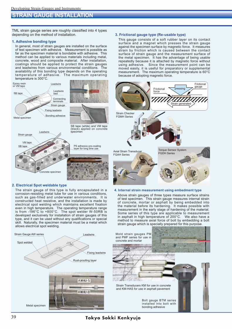
39
Developing Strain Gauges and Instruments
4. Internal strain measurement using embedment typeAbove strain gauges of three types measure surface strains of test specimen. This strain gauge measures internal strain of concrete, mortar or asphalt by being embedded into the material before its hardening. It makes possible with measurement in the early stage of hardening of the material. Some series of this type are applicable to measurement in asphalt in high temperature of 200°C. We also have a method to measure axial force of bolt by embedding a bolt strain gauge which is specially prepared for this purpose.
3. Frictional gauge type (Re-usable type)This gauge consists of a soft rubber layer on its contact sur face and a magnet which presses the strain gauge against the specimen surface by magnetic force. It measures strain by friction which is caused between the contact surface of strain gauge and the measurement surface of the metal specimen. It has the advantage of being usable repeatedly because it is attached by magnetic force without using adhesive. Since the measurement point can be moved easily, it is useful for preparatory or supplemental measurement. The maximum operating temperature is 60°C because of adopting magnetic force.
TML strain gauge series are roughly classified into 4 types depending on the method of installation.
1. Adhesive bonding typeIn general, most of strain gauges are installed on the surface of test specimen with adhesive. Measurement is possible as far as the specimen material is bondable with adhesive. This method can be applied to various materials including metal, concrete, wood and composite material. After installation, coatings should be applied to protect the strain gauges and leadwires from various environmental conditions. The availability of this bonding type depends on the operating temperature of adhesive. The maximum operat ing temperature is 300°C.
2. Electrical Spot weldable typeThe strain gauge of this type is fully encapsulated in a corrosion-resisting metal tube for use in various conditions, such as gas-f illed and underwater environments. It is constructed heat resistive, and the installation is made by electrical spot welding which maintains excellent fixation even in high temperature. The operating temperature range is from -196°C to +800°C. The spot welder W-50RB is developed exclusively for installation of strain gauges of this type, and it can be used without any qualifications or special skill. Naturally, the specimen material must be a metal which allows electrical spot welding.
Epoxy resinor VM tape
SB tape
Leadwire
Leadwirebed
Connecting terminals
Strain gauge
Fixing leadwire
Bonding adhesive
Strain gauge
SB tapeVM tape
PS adhesive pre-coating layer for long time use
Concrete specimen
Metal specimen
Strain Gauge AW series
Spot welded
Leadwire
Fixing leadwire
Rust-proofing layer
Metal specimen
SB tape (white) and VM tape (black) applied on concrete specimen
Frictional force
pressing
Strain generated
Frictional gauge
Strain CheckerFGMH Series
Axial Strain TransducerFGAH Series
Torque Sensor SystemFGDH Series
Bolt gauge BTM series installed into bolt with bonding adhesive
Strain Transducers KM for use in concreteand KM-HAS for use in asphalt pavement
Mold strain gauges PM and PMF series for use in concrete and mortar
Leadwire
STRAIN GAUGE INSTALLATION
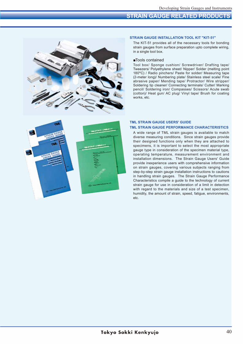
40
Developing Strain Gauges and Instruments
TML STRAIN GAUGE USERS' GUIDETML STRAIN GAUGE PERFORMANCE CHARACTERISTICS
A wide range of TML strain gauges is available to match diverse measuring conditions. Since strain gauges provide their designed functions only when they are attached to specimens, it is important to select the most appropriate gauge type in consideration of the specimen material type, operating temperature, measurement environment and installation dimensions. The Strain Gauge Users' Guide provide inexperience users with comprehensive information on strain gauges, covering various subjects ranging from step-by-step strain gauge installation instructions to cautions in handling strain gauges. The Strain Gauge Performance Characteristics compile a guide to the technology of current strain gauge for use in consideration of a limit in detection with regard to the materials and size of a test specimen, humidity, the amount of strain, speed, fatigue, environments, etc.
STRAIN GAUGE INSTALLATION TOOL KIT "KIT-51"The KIT-51 provides all of the necessary tools for bonding strain gauges from surface preparation upto complete wiring, in a single tool box.
Tools containedTool box/ Sponge cushion/ Screwdriver/ Drafting tape/ Tweezers/ Polyethylene sheet/ Nipper/ Solder (melting point 180°C) / Radio pinchers/ Paste for solder/ Measuring tape (2-meter long)/ Numbering plate/ Stainless steel scale/ Fine abrasive paper/ Mending tape/ Protractor/ Wire stripper/ Soldering tip cleaner/ Connecting terminals/ Cutter/ Marking pencil/ Soldering iron/ Compasses/ Scissors/ Acute swab (cotton)/ Heat gun/ AC plug/ Vinyl tape/ Brush for coating works, etc.
STRAIN GAUGE RELATED PRODUCTS
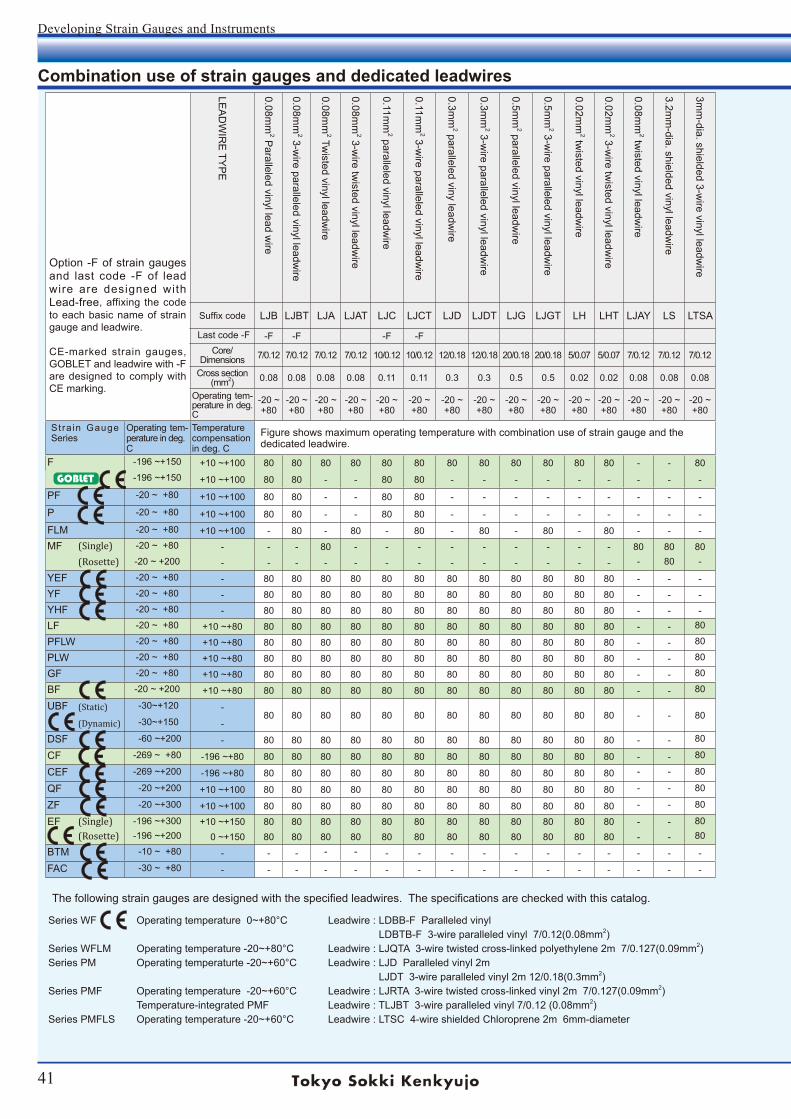
41
Developing Strain Gauges and Instruments
(Rosette)
Option -F of strain gauges and last code -F of lead wire are designed with Lead-free, affixing the code to each basic name of strain gauge and leadwire.
CE-marked strain gauges, GOBLET and leadwire with -F are designed to comply with CE marking.
LEA
DW
IRE
TYP
E
0.08mm
2 Paralleled vinyl lead w
ire
0.08mm
2 3-wire paralleled vinyl leadw
ire
0.08mm
2 Twisted vinyl leadw
ire
0.08mm
2 3-wire tw
isted vinyl leadwire
0.11mm
2 paralleled vinyl leadwire
0.11mm
2 3-wire paralleled vinyl leadw
ire
0.3mm
2 paralleled viny leadwire
0.3mm
2 3-wire paralleled vinyl leadw
ire
0.5mm
2 paralleled vinyl leadwire
0.5mm
2 3-wire paralleled vinyl leadw
ire
0.02mm
2 twisted vinyl leadw
ire
0.02mm
2 3-wire tw
isted vinyl leadwire
0.08mm
2 twisted vinyl leadw
ire
3.2mm
-dia. shielded vinyl leadwire
3mm
-dia. shielded 3-wire vinyl leadw
ire
5mm
-dia. shielded 3-wire vinyl leadw
ire
0.08mm
2 polypropyrene 4-wire paralleled
lead wire w
ith modular plug
0.08mm
2 vinyl 4-wire paralleled leadw
ire
3-wir paralleled special vinyl leadw
ire
2-wire tw
isted cross-linked vinyl leadwire
3-wire tw
isted cross-linked vinyl leadwire
3-wire tw
isted cross-linked polyethylene leadw
ire
Temperature-integrated 3-w
ire paralleled vinyl leadw
ire
Temperature-integrated 4-w
ire paralleled vinyl leadw
ire
Temperature-integrated 3-w
ire twisted
fluorinated resin (FEP
) leadwire
0.14mm
-dia. polyurethane leadwire
0.18mm
-dia. polyurethane leadwire
0.14mm
-dia. polyester leadwire
0.18mm
-dia. polyester leadwire
0.14mm
-dia. polyimide leadw
ire0.18m
m-dia. polyim
ide leadwire
3-wire tw
isted fluorinated resin (FEP
) leadw
ire
3-wire tw
isted fluorinated resin (FEP
) leadw
ire No Tetra-Etch required for surface
3-wire tw
isted fluorinated resin (FEP
) leadw
ire
3-wire tw
isted fluorinated resin (FEP
) leadw
ire
1.5mm
-dia. 3-wire tw
isted fluorinated resin (FE
P) leadw
ire with shield
3-wire tw
isted fluorinated resin (PTFE
) leadw
ire
3-wire tw
isted fluorinated resin (PTFE
) leadw
ire
Suffix code LJB LJBT LJA LJAT LJC LJCT LJD LJDT LJG LJGT LH LHT LJAY LS LTSA LTSB LQM LBQM LXT LJRA LJRTA LJQTA TLJBT TLQ 6FB_TLT* LP LU LE 6FA_
LT*6FAS_LT*
6FB_LT*
6FC_LT*
6FD_LTS*
4FA_LT*
4FB_LT*
Last code -F -F -F -F -F -F -F -F -F -F -F -F -F -F -F -F -F -F -FCore/
Dimensions 7/0.12 7/0.12 7/0.12 7/0.12 10/0.12 10/0.12 12/0.18 12/0.18 20/0.18 20/0.18 5/0.07 5/0.07 7/0.12 7/0.12 7/0.12 7/0.26 7/0.12 7/0.12 7/0.12 7/0.16 7/0.127 7/0.127 7/0.12 7/0.12 1/0.2 1/0.141/0.18
1/0.141/0.18
1/0.141/0.18 7/0.18 7/0.18 1/0.2 7/0.08 7/0.08 7/0.16 1/0.2
Cross section(mm2) 0.08 0.08 0.08 0.08 0.11 0.11 0.3 0.3 0.5 0.5 0.02 0.02 0.08 0.08 0.08 0.3 0.08 0.08 0.08 0.14 0.09 0.09 0.08 0.08 0.18 0.18 0.04 0.04 0.14
Operating tem-perature in deg. C
-20 ~ +80
-20 ~ +80
-20 ~ +80
-20 ~ +80
-20 ~ +80
-20 ~ +80
-20 ~ +80
-20 ~ +80
-20 ~ +80
-20 ~ +80
-20 ~ +80
-20 ~ +80
-20 ~ +80
-20 ~ +80
-20 ~ +80
-20 ~ +80
-20 ~ +100
-20 ~ +80
-20 ~ +150
-20 ~ +100
-20 ~ +100
-65 ~ +125
-20 ~ +80
-20 ~ +80
-269 ~ +200
-10 ~ +120
-196 ~ +200
-269 ~ +300
-269 ~ +200
-269 ~ +200
-269 ~ +200
-269 ~ +200
-269 ~ +200
-269 ~ +260
-269 ~ +200
Stra in Gauge Series
Operating tem-perature in deg.C
Temperaturecompensationin deg. C
Figure shows maximum operating temperature with combination use of strain gauge and the dedicated leadwire. Figure shows maximum operating temperature with combination use of strain gauge and the dedicated leadwire.
F -196 ~+150 +10 ~+100 80 80 80 80 80 80 80 80 80 80 80 80 - - 80 80 100 80 150 100 100 100 80 80 150 120 150 150 150 150 150 150 - 150 150-196 ~+150 +10 ~+100 80 80 - - 80 80 - - - - - - - - - - 100 80 150 - - - 80 - - 120 150 150 - - - - - - -
PF -20 ~ +80 +10 ~+100 80 80 - - 80 80 - - - - - - - - - - 80 80 80 - - - 80 - - 80 80 80 - - - - - - -
P -20 ~ +80 +10 ~+100 80 80 - - 80 80 - - - - - - - - - - 80 80 80 - - - - - - 80 80 80 - - - - - - -
FLM -20 ~ +80 +10 ~+100 - 80 - 80 - 80 - 80 - 80 - 80 - - - 80 - - 80 - 80 80 80 80 80 80 80 80 80 80 80 80 - 80 80MF (Single) -20 ~ +80 - - - 80 - - - - - - - - - 80 80 80 - - - - - - - - - - 80 80 80 - - - - 80 - -
(Rosette) -20 ~ +200 - - - - - - - - - - - - - - 80 - - - - - - - - - - - 120 200 200 - - - - 200 - -YEF -20 ~ +80 - 80 80 80 80 80 80 80 80 80 80 80 80 - - - 80 80 80 80 80 80 80 80 80 80 80 80 80 80 80 80 - 80 80YF -20 ~ +80 - 80 80 80 80 80 80 80 80 80 80 80 80 - - - 80 80 80 80 80 80 80 80 80 80 80 80 80 80 80 80 - 80 80YHF -20 ~ +80 - 80 80 80 80 80 80 80 80 80 80 80 80 - - - 80 80 80 80 80 80 80 80 80 80 80 80 80 80 80 80 - 80 80LF -20 ~ +80 +10 ~+80 80 80 80 80 80 80 80 80 80 80 80 80 - - 80 80 80 80 80 80 80 80 80 80 80 80 80 80 80 80 80 80 - 80 80PFLW -20 ~ +80 +10 ~+80 80 80 80 80 80 80 80 80 80 80 80 80 - - 80 80 80 80 80 80 80 80 80 80 80 80 80 80 80 80 80 80 - 80 80PLW -20 ~ +80 +10 ~+80 80 80 80 80 80 80 80 80 80 80 80 80 - - 80 80 80 80 80 80 80 80 80 80 80 80 80 80 80 80 80 80 - 80 80GF -20 ~ +80 +10 ~+80 80 80 80 80 80 80 80 80 80 80 80 80 - - 80 80 80 80 80 80 80 80 80 80 80 80 80 80 80 80 80 80 - 80 80BF -20 ~ +200 +10 ~+80 80 80 80 80 80 80 80 80 80 80 80 80 - - 80 80 100 80 150 100 100 125 80 80 200 120 200 200 200 200 200 200 - 200 200UBF (Static) -30~+120 -
80 80 80 80 80 80 80 80 80 80 80 80 - - 80 80 100 80120
100 100120
80 80120
120120 120 120 120 120 120 - 120 120
(Dynamic) -30~+150 - 150 125 150 150 150 150 150 150 150 - 150 150DSF -60 ~+200 - 80 80 80 80 80 80 80 80 80 80 80 80 - - 80 80 100 80 150 100 100 125 80 80 200 120 200 200 200 200 200 200 - 200 200CF -269 ~ +80 -196 ~+80 80 80 80 80 80 80 80 80 80 80 80 80 - - 80 80 80 80 80 80 80 80 80 80 80 80 80 80 80 80 80 80 - 80 80CEF -269 ~+200 -196 ~+80 80 80 80 80 80 80 80 80 80 80 80 80 - - 80 80 100 80 150 100 100 125 80 80 200 120 200 200 200 200 200 200 - 200 200QF -20 ~+200 +10 ~+100 80 80 80 80 80 80 80 80 80 80 80 80 - - 80 80 100 80 150 100 100 125 80 80 200 120 200 200 200 200 200 200 - 200 200ZF -20 ~+300 +10 ~+100 80 80 80 80 80 80 80 80 80 80 80 80 - - 80 80 100 80 150 100 100 125 80 80 200 120 200 300 200 200 200 200 - 260 260EF (Single) -196 ~+300 +10 ~+150 80 80 80 80 80 80 80 80 80 80 80 80 - - 80 80 100 80 150 100 100 125 80 80 200 120 200 300 200 200 200 200 - 260 260
(Rosette) -196 ~+200 0 ~+150 80 80 80 80 80 80 80 80 80 80 80 80 - - 80 80 100 80 150 100 100 125 80 80 200 120 200 200 200 200 200 200 - 200 200BTM -10 ~ +80 - - - - - - - - - - - - - - - - - - - - - - - - - - 80 - 80 - - - - - 80 80FAC -30 ~ +80 - - - - - - - - - - - - - - - - - - - - - - - - - - 80 - 80 - - - - - - -
GOBLET
Combination use of strain gauges and dedicated leadwires
The following strain gauges are designed with the specified leadwires. The specifications are checked with this catalog.
Series WF Operating temperature 0~+80°C Leadwire : LDBB-F Paralleled vinyl LDBTB-F 3-wire paralleled vinyl 7/0.12(0.08mm2)Series WFLM Operating temperature -20~+80°C Leadwire : LJQTA 3-wire twisted cross-linked polyethylene 2m 7/0.127(0.09mm2)Series PM Operating temperaturte -20~+60°C Leadwire : LJD Paralleled vinyl 2m LJDT 3-wire paralleled vinyl 2m 12/0.18(0.3mm2)Series PMF Operating temperature -20~+60°C Leadwire : LJRTA 3-wire twisted cross-linked vinyl 2m 7/0.127(0.09mm2) Temperature-integrated PMF Leadwire : TLJBT 3-wire paralleled vinyl 7/0.12 (0.08mm2)Series PMFLS Operating temperature -20~+60°C Leadwire : LTSC 4-wire shielded Chloroprene 2m 6mm-diameter
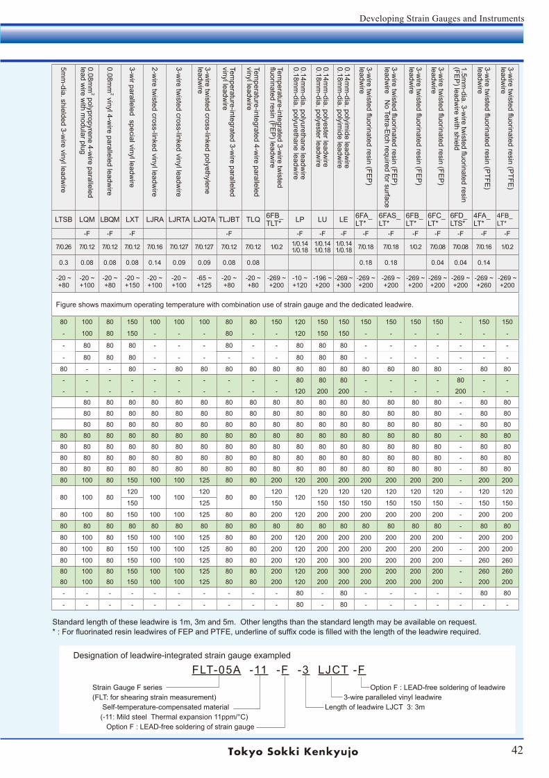
42
Developing Strain Gauges and Instruments
Option -F of strain gauges and last code -F of lead wire are designed with Lead-free, affixing the code to each basic name of strain gauge and leadwire.
CE-marked strain gauges, GOBLET and leadwire with -F are designed to comply with CE marking.
LEA
DW
IRE
TYP
E
0.08mm
2 Paralleled vinyl lead w
ire
0.08mm
2 3-wire paralleled vinyl leadw
ire
0.08mm
2 Twisted vinyl leadw
ire
0.08mm
2 3-wire tw
isted vinyl leadwire
0.11mm
2 paralleled vinyl leadwire
0.11mm
2 3-wire paralleled vinyl leadw
ire
0.3mm
2 paralleled viny leadwire
0.3mm
2 3-wire paralleled vinyl leadw
ire
0.5mm
2 paralleled vinyl leadwire
0.5mm
2 3-wire paralleled vinyl leadw
ire
0.02mm
2 twisted vinyl leadw
ire
0.02mm
2 3-wire tw
isted vinyl leadwire
0.08mm
2 twisted vinyl leadw
ire
3.2mm
-dia. shielded vinyl leadwire
3mm
-dia. shielded 3-wire vinyl leadw
ire
5mm
-dia. shielded 3-wire vinyl leadw
ire
0.08mm
2 polypropyrene 4-wire paralleled
lead wire w
ith modular plug
0.08mm
2 vinyl 4-wire paralleled leadw
ire
3-wir paralleled special vinyl leadw
ire
2-wire tw
isted cross-linked vinyl leadwire
3-wire tw
isted cross-linked vinyl leadwire
3-wire tw
isted cross-linked polyethylene leadw
ire
Temperature-integrated 3-w
ire paralleled vinyl leadw
ire
Temperature-integrated 4-w
ire paralleled vinyl leadw
ire
Temperature-integrated 3-w
ire twisted
fluorinated resin (FEP
) leadwire
0.14mm
-dia. polyurethane leadwire
0.18mm
-dia. polyurethane leadwire
0.14mm
-dia. polyester leadwire
0.18mm
-dia. polyester leadwire
0.14mm
-dia. polyimide leadw
ire0.18m
m-dia. polyim
ide leadwire
3-wire tw
isted fluorinated resin (FEP
) leadw
ire
3-wire tw
isted fluorinated resin (FEP
) leadw
ire No Tetra-Etch required for surface
3-wire tw
isted fluorinated resin (FEP
) leadw
ire
3-wire tw
isted fluorinated resin (FEP
) leadw
ire
1.5mm
-dia. 3-wire tw
isted fluorinated resin (FE
P) leadw
ire with shield
3-wire tw
isted fluorinated resin (PTFE
) leadw
ire
3-wire tw
isted fluorinated resin (PTFE
) leadw
ire
Suffix code LJB LJBT LJA LJAT LJC LJCT LJD LJDT LJG LJGT LH LHT LJAY LS LTSA LTSB LQM LBQM LXT LJRA LJRTA LJQTA TLJBT TLQ 6FB_TLT* LP LU LE 6FA_
LT*6FAS_LT*
6FB_LT*
6FC_LT*
6FD_LTS*
4FA_LT*
4FB_LT*
Last code -F -F -F -F -F -F -F -F -F -F -F -F -F -F -F -F -F -F -FCore/
Dimensions 7/0.12 7/0.12 7/0.12 7/0.12 10/0.12 10/0.12 12/0.18 12/0.18 20/0.18 20/0.18 5/0.07 5/0.07 7/0.12 7/0.12 7/0.12 7/0.26 7/0.12 7/0.12 7/0.12 7/0.16 7/0.127 7/0.127 7/0.12 7/0.12 1/0.2 1/0.141/0.18
1/0.141/0.18
1/0.141/0.18 7/0.18 7/0.18 1/0.2 7/0.08 7/0.08 7/0.16 1/0.2
Cross section(mm2) 0.08 0.08 0.08 0.08 0.11 0.11 0.3 0.3 0.5 0.5 0.02 0.02 0.08 0.08 0.08 0.3 0.08 0.08 0.08 0.14 0.09 0.09 0.08 0.08 0.18 0.18 0.04 0.04 0.14
Operating tem-perature in deg. C
-20 ~ +80
-20 ~ +80
-20 ~ +80
-20 ~ +80
-20 ~ +80
-20 ~ +80
-20 ~ +80
-20 ~ +80
-20 ~ +80
-20 ~ +80
-20 ~ +80
-20 ~ +80
-20 ~ +80
-20 ~ +80
-20 ~ +80
-20 ~ +80
-20 ~ +100
-20 ~ +80
-20 ~ +150
-20 ~ +100
-20 ~ +100
-65 ~ +125
-20 ~ +80
-20 ~ +80
-269 ~ +200
-10 ~ +120
-196 ~ +200
-269 ~ +300
-269 ~ +200
-269 ~ +200
-269 ~ +200
-269 ~ +200
-269 ~ +200
-269 ~ +260
-269 ~ +200
Stra in Gauge Series
Operating tem-perature in deg.C
Temperaturecompensationin deg. C
Figure shows maximum operating temperature with combination use of strain gauge and the dedicated leadwire. Figure shows maximum operating temperature with combination use of strain gauge and the dedicated leadwire.
F -196 ~+150 +10 ~+100 80 80 80 80 80 80 80 80 80 80 80 80 - - 80 80 100 80 150 100 100 100 80 80 150 120 150 150 150 150 150 150 - 150 150-196 ~+150 +10 ~+100 80 80 - - 80 80 - - - - - - - - - - 100 80 150 - - - 80 - - 120 150 150 - - - - - - -
PF -20 ~ +80 +10 ~+100 80 80 - - 80 80 - - - - - - - - - - 80 80 80 - - - 80 - - 80 80 80 - - - - - - -
P -20 ~ +80 +10 ~+100 80 80 - - 80 80 - - - - - - - - - - 80 80 80 - - - - - - 80 80 80 - - - - - - -
FLM -20 ~ +80 +10 ~+100 - 80 - 80 - 80 - 80 - 80 - 80 - - - 80 - - 80 - 80 80 80 80 80 80 80 80 80 80 80 80 - 80 80MF (Single) -20 ~ +80 - - - 80 - - - - - - - - - 80 80 80 - - - - - - - - - - 80 80 80 - - - - 80 - -
(Rosette) -20 ~ +200 - - - - - - - - - - - - - - 80 - - - - - - - - - - - 120 200 200 - - - - 200 - -YEF -20 ~ +80 - 80 80 80 80 80 80 80 80 80 80 80 80 - - - 80 80 80 80 80 80 80 80 80 80 80 80 80 80 80 80 - 80 80YF -20 ~ +80 - 80 80 80 80 80 80 80 80 80 80 80 80 - - - 80 80 80 80 80 80 80 80 80 80 80 80 80 80 80 80 - 80 80YHF -20 ~ +80 - 80 80 80 80 80 80 80 80 80 80 80 80 - - - 80 80 80 80 80 80 80 80 80 80 80 80 80 80 80 80 - 80 80LF -20 ~ +80 +10 ~+80 80 80 80 80 80 80 80 80 80 80 80 80 - - 80 80 80 80 80 80 80 80 80 80 80 80 80 80 80 80 80 80 - 80 80PFLW -20 ~ +80 +10 ~+80 80 80 80 80 80 80 80 80 80 80 80 80 - - 80 80 80 80 80 80 80 80 80 80 80 80 80 80 80 80 80 80 - 80 80PLW -20 ~ +80 +10 ~+80 80 80 80 80 80 80 80 80 80 80 80 80 - - 80 80 80 80 80 80 80 80 80 80 80 80 80 80 80 80 80 80 - 80 80GF -20 ~ +80 +10 ~+80 80 80 80 80 80 80 80 80 80 80 80 80 - - 80 80 80 80 80 80 80 80 80 80 80 80 80 80 80 80 80 80 - 80 80BF -20 ~ +200 +10 ~+80 80 80 80 80 80 80 80 80 80 80 80 80 - - 80 80 100 80 150 100 100 125 80 80 200 120 200 200 200 200 200 200 - 200 200UBF (Static) -30~+120 -
80 80 80 80 80 80 80 80 80 80 80 80 - - 80 80 100 80120
100 100120
80 80120
120120 120 120 120 120 120 - 120 120
(Dynamic) -30~+150 - 150 125 150 150 150 150 150 150 150 - 150 150DSF -60 ~+200 - 80 80 80 80 80 80 80 80 80 80 80 80 - - 80 80 100 80 150 100 100 125 80 80 200 120 200 200 200 200 200 200 - 200 200CF -269 ~ +80 -196 ~+80 80 80 80 80 80 80 80 80 80 80 80 80 - - 80 80 80 80 80 80 80 80 80 80 80 80 80 80 80 80 80 80 - 80 80CEF -269 ~+200 -196 ~+80 80 80 80 80 80 80 80 80 80 80 80 80 - - 80 80 100 80 150 100 100 125 80 80 200 120 200 200 200 200 200 200 - 200 200QF -20 ~+200 +10 ~+100 80 80 80 80 80 80 80 80 80 80 80 80 - - 80 80 100 80 150 100 100 125 80 80 200 120 200 200 200 200 200 200 - 200 200ZF -20 ~+300 +10 ~+100 80 80 80 80 80 80 80 80 80 80 80 80 - - 80 80 100 80 150 100 100 125 80 80 200 120 200 300 200 200 200 200 - 260 260EF (Single) -196 ~+300 +10 ~+150 80 80 80 80 80 80 80 80 80 80 80 80 - - 80 80 100 80 150 100 100 125 80 80 200 120 200 300 200 200 200 200 - 260 260
(Rosette) -196 ~+200 0 ~+150 80 80 80 80 80 80 80 80 80 80 80 80 - - 80 80 100 80 150 100 100 125 80 80 200 120 200 200 200 200 200 200 - 200 200BTM -10 ~ +80 - - - - - - - - - - - - - - - - - - - - - - - - - - 80 - 80 - - - - - 80 80FAC -30 ~ +80 - - - - - - - - - - - - - - - - - - - - - - - - - - 80 - 80 - - - - - - -
Standard length of these leadwire is 1m, 3m and 5m. Other lengths than the standard length may be available on request.* : For fluorinated resin leadwires of FEP and PTFE, underline of suffix code is filled with the length of the leadwire required.
Designation of leadwire-integrated strain gauge exampled
FLT-05A -11 -F -3 LJCT -F Strain Gauge F series Option F : LEAD-free soldering of leadwire (FLT: for shearing strain measurement) 3-wire paralleled vinyl leadwire Self-temperature-compensated material Length of leadwire LJCT 3: 3m (-11: Mild steel Thermal expansion 11ppm/°C) Option F : LEAD-free soldering of strain gauge
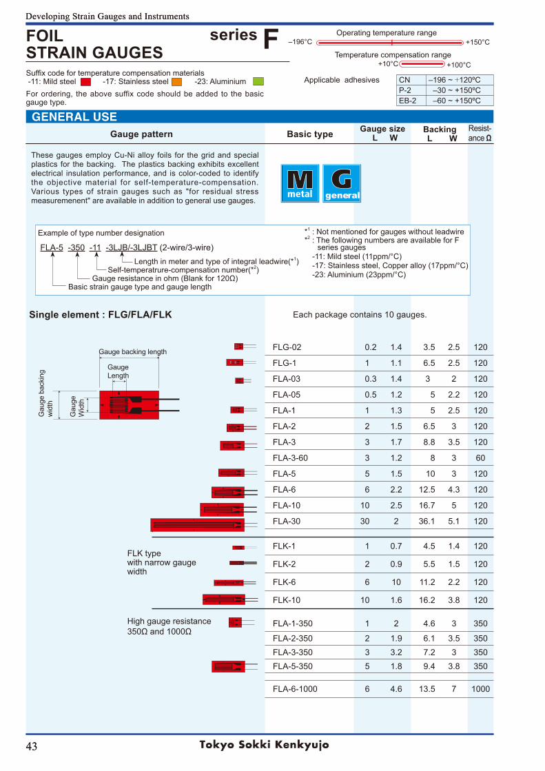
43
Developing Strain Gauges and Instruments
Suffix code for temperature compensation materials -11: Mild steel -17: Stainless steel -23: AluminiumFor ordering, the above suffix code should be added to the basic gauge type.
43
general
Example of type number designation
FLA-5 -350 -11 -3LJB/-3LJBT (2-wire/3-wire) Length in meter and type of integral leadwire(*1) Self-temperatrure-compensation number(*2) Gaugeresistanceinohm(Blankfor120Ω) Basic strain gauge type and gauge length
*1 : Not mentioned for gauges without leadwire*2 : The following numbers are available for F series gauges
-11: Mild steel (11ppm/°C)-17: Stainless steel, Copper alloy (17ppm/°C)-23: Aluminium (23ppm/°C)
Gauge pattern Basic type Gauge size L W
Backing L W
Resist-ance Ω
FOIL STRAIN GAUGES
+100°C
Applicable adhesives CN ‒196~+120ºCP-2 ‒30~+150ºCEB-2 ‒60~+150ºC
Developing Strain Gauges and Instruments
Operating temperature range
Temperature compensation range+10°C
+150°C‒196°Cseries F
FLG-02 0.2 1.4 3.5 2.5 120
FLG-1 1 1.1 6.5 2.5 120
FLA-03 0.3 1.4 3 2 120
FLA-05 0.5 1.2 5 2.2 120
FLA-1 1 1.3 5 2.5 120
FLA-2 2 1.5 6.5 3 120
FLA-3 3 1.7 8.8 3.5 120
FLA-3-60 3 1.2 8 3 60
FLA-5 5 1.5 10 3 120
FLA-6 6 2.2 12.5 4.3 120
FLA-10 10 2.5 16.7 5 120
FLA-30 30 2 36.1 5.1 120
FLK-1 1 0.7 4.5 1.4 120
FLK-2 2 0.9 5.5 1.5 120
FLK-6 6 10 11.2 2.2 120
FLK-10 10 1.6 16.2 3.8 120
FLA-1-350 1 2 4.6 3 350
FLA-2-350 2 1.9 6.1 3.5 350FLA-3-350 3 3.2 7.2 3 350FLA-5-350 5 1.8 9.4 3.8 350
FLA-6-1000 6 4.6 13.5 7 1000
These gauges employ Cu-Ni alloy foils for the grid and special plastics for the backing. The plastics backing exhibits excellent electrical insulation performance, and is color-coded to identify the objective material for self-temperature-compensation. Various types of strain gauges such as "for residual stress measuremenent" are available in addition to general use gauges.
Single element : FLG/FLA/FLK Each package contains 10 gauges.
FLK type with narrow gauge width
Gauge backing length
Gauge Length
Gau
ge
Wid
th
Gau
ge b
acki
ng
wid
th
GENERAL USE
High gauge resistance 350Ωand1000Ω
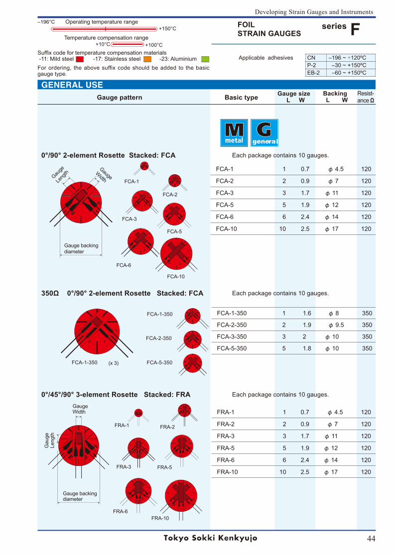
44
Developing Strain Gauges and Instruments
Suffix code for temperature compensation materials -11: Mild steel -17: Stainless steel -23: AluminiumFor ordering, the above suffix code should be added to the basic gauge type.
FOIL STRAIN GAUGES
series FApplicable adhesives CN ‒196~+120ºC
P-2 ‒30~+150ºCEB-2 ‒60~+150ºC
general
FCA-1-350 1 1.6 φ 8 350
FCA-2-350 2 1.9 φ 9.5 350
FCA-3-350 3 2 φ 10 350
FCA-5-350 5 1.8 φ 10 350
(x 3)
FCA-1-350
FCA-2-350
FCA-5-350FCA-1-350
350Ω 0°/90° 2-element Rosette Stacked: FCA Each package contains 10 gauges.
FRA-10
FRA-1 1 0.7 φ 4.5 120
FRA-2 2 0.9 φ 7 120
FRA-3 3 1.7 φ 11 120
FRA-5 5 1.9 φ 12 120
FRA-6 6 2.4 φ 14 120
FRA-10 10 2.5 φ 17 120
FRA-1 FRA-2
FRA-3 FRA-5
FRA-6
0°/45°/90° 3-element Rosette Stacked: FRA Each package contains 10 gauges.
Gauge Width
Gau
ge
Leng
th
Gauge backing diameter
+100°C
Operating temperature range
Temperature compensation range+10°C
+150°C‒196°C
Gauge pattern Basic type Gauge size L W
Backing L W
Resist-ance Ω
FCA-1 1 0.7 φ 4.5 120
FCA-2 2 0.9 φ 7 120
FCA-3 3 1.7 φ 11 120
FCA-5 5 1.9 φ 12 120
FCA-6 6 2.4 φ 14 120
FCA-10 10 2.5 φ 17 120
FCA-1
FCA-2
FCA-3
FCA-5
FCA-6
FCA-10
0°/90° 2-element Rosette Stacked: FCA Each package contains 10 gauges.
Gauge WidthGau
ge
Leng
th
Gauge backing diameter
GENERAL USE
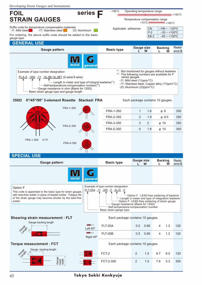
45
Developing Strain Gauges and Instruments
Suffix code for temperature compensation materials -11: Mild steel -17: Stainless steel -23: AluminiumFor ordering, the above suffix code should be added to the basic gauge type.
350Ω 0°/45°/90° 3-element Rosette Stacked: FRA Each package contains 10 gauges.
Gauge pattern Basic type Gauge size L W
Backing L W
Resist-ance Ω
FLT-05A 0.5 0.66 4 1.3 120
FLT-05B 0.5 0.66 4 1.3 120
FCT-2 2 1.5 8.7 6.5 120
FCT-2-350 2 1.5 7.6 5.3 350
Shearing strain measurement : FLT Each package contains 10 gauges.
Torque measurement : FCT Each package contains 10 gauges.
SPECIAL USE
Gauge
Le
ngth
Gauge backing length
Left 45°
Right 45°
Gauge backing length
Gauge
Le
ngth
Gau
ge
base
w
idth
Example of type number designation
FLT-05A -11 -350 -F -3LJC -F
Option F : LEAD-free soldering of leadwire Length in meter and type of integration leadwire Option F: LEAD-free soldering of strain gauge Gaugeresistance(Blankfor120Ω) Self-temperature-compensation number Basic strain gauge type
Option FThis code is appended to the basic type for strain gauges with lead-free solder in place of leaded solder. Fatigue life of the strain gauge may become shorter by the lead-free solder.
Example of type number designation
FLA-5 -350 -11 -3LJB/-3LJBT (2-wire/3-wire) Length in meter and type of integral leadwire(*1) Self-temperatrure-compensation number(*2) Gaugeresistanceinohm(Blankfor120Ω) Basic strain gauge type and gauge length
*1 : Not mentioned for gauges without leadwire*2 : The following numbers are available for F series gauges
-11: Mild steel (11ppm/°C)-17: Stainless steel, Copper alloy (17ppm/°C)-23: Aluminium (23ppm/°C)
general
general
GENERAL USEGauge pattern Basic type Gauge size
L WBacking L W
Resist-ance Ω
FOIL STRAIN GAUGES
series F+100°C
Applicable adhesives CN ‒196~+120ºCP-2 ‒30~+150ºCEB-2 ‒60~+150ºC
Operating temperature range
Temperature compensation range+10°C
+150°C‒196°C
FRA-1-350 1 1.6 φ 8 350
FRA-2-350 2 1.9 φ 9.5 350
FRA-3-350 3 2 φ 10 350
FRA-5-350 5 1.8 φ 10 350
(x 3)
FRA-1-350
FRA-2-350
FRA-5-350FRA-1-350
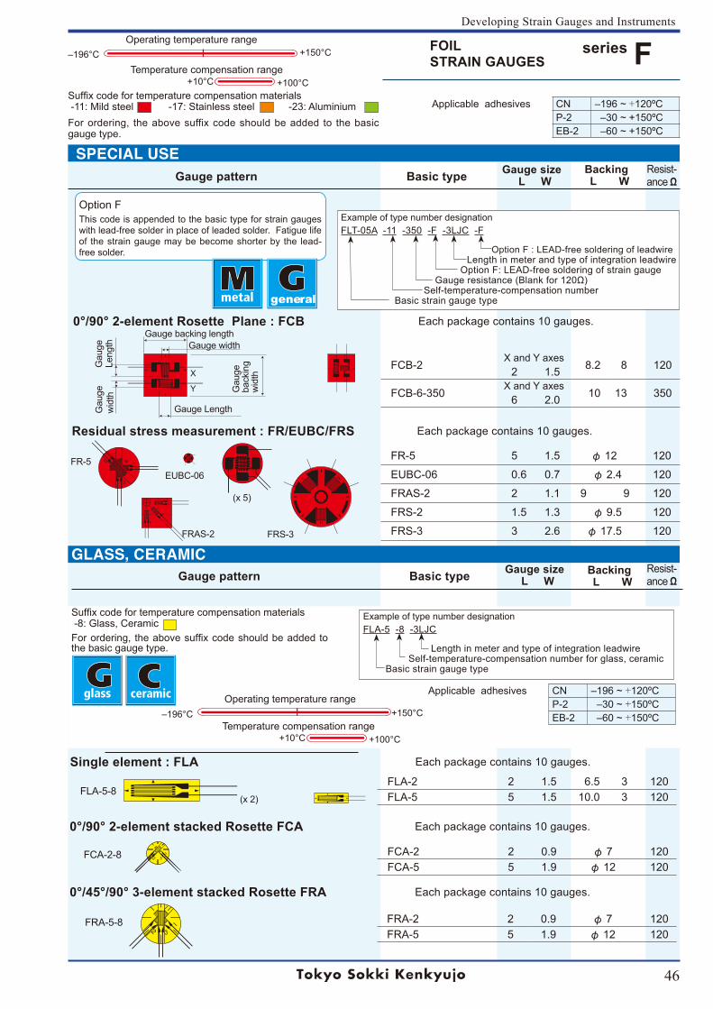
46
Developing Strain Gauges and Instruments
Suffix code for temperature compensation materials -11: Mild steel -17: Stainless steel -23: AluminiumFor ordering, the above suffix code should be added to the basic gauge type.
FCB-2X and Y axes
8.2 8 120 2 1.5
FCB-6-350X and Y axes
10 13 3506 2.0
FR-5 5 1.5 φ 12 120
EUBC-06 0.6 0.7 φ 2.4 120
FRAS-2 2 1.1 99 120
FRS-2 1.5 1.3 φ 9.5 120
FRS-3 3 2.6 φ 17.5 120
EUBC-06FR-5
FRAS-2 FRS-3
(x 5)
0°/90° 2-element Rosette Plane : FCB Each package contains 10 gauges.
Residual stress measurement : FR/EUBC/FRS Each package contains 10 gauges.
Gauge backing length
Gau
ge
back
ing
wid
th
Gauge Length
Gau
geLe
ngth
X
Y
Gau
ge
wid
th
Gauge width
Example of type number designation
FLT-05A -11 -350 -F -3LJC -F
Option F : LEAD-free soldering of leadwire Length in meter and type of integration leadwire Option F: LEAD-free soldering of strain gauge Gaugeresistance(Blankfor120Ω) Self-temperature-compensation number Basic strain gauge type
Option FThis code is appended to the basic type for strain gauges with lead-free solder in place of leaded solder. Fatigue life of the strain gauge may be become shorter by the lead-free solder.
general
FOIL STRAIN GAUGES
series FApplicable adhesives CN ‒196~+120ºC
P-2 ‒30~+150ºCEB-2 ‒60~+150ºC
+100°CTemperature compensation range
+10°C
Operating temperature range+150°C‒196°C
Gauge pattern Basic type Gauge size L W
Backing L W
Resist-ance Ω
GLASS, CERAMIC
Suffixcodefortemperaturecompensationmaterials -8: Glass, Ceramic Forordering, theabovesuffixcodeshouldbeaddedtothe basic gauge type.
+100°C
Operating temperature range
+10°CTemperature compensation range
+150°C‒196°C
Applicable adhesives CN ‒196~+120ºCP-2 ‒30~+150ºCEB-2 ‒60~+150ºC
FLA-2 2 1.5 6.5 3 120FLA-5 5 1.5 10.0 3 120
FCA-2 2 0.9 φ 7 120FCA-5 5 1.9 φ 12 120
FRA-2 2 0.9 φ 7 120FRA-5 5 1.9 φ 12 120
FLA-5-8(x 2)
FCA-2-8
FRA-5-8
Single element : FLA Each package contains 10 gauges.
0°/90° 2-element stacked Rosette FCA Each package contains 10 gauges.
0°/45°/90° 3-element stacked Rosette FRA Each package contains 10 gauges.
Example of type number designation
FLA-5 -8 -3LJC
Length in meter and type of integration leadwire Self-temperature-compensation number for glass, ceramic Basic strain gauge type
SPECIAL USEGauge pattern Basic type Gauge size
L WBacking L W
Resist-ance Ω
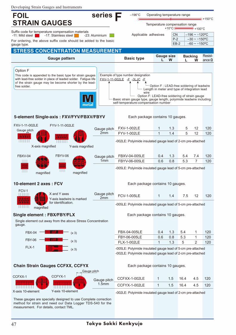
47
Developing Strain Gauges and Instruments
Suffix code for temperature compensation materials -11: Mild steel -17: Stainless steel -23: AluminiumFor ordering, the above suffix code should be added to the basic gauge type.
Gauge pitch
+100°C
Operating temperature range
+10°CTemperature compensation range
+150°C‒196°C
Example of type number designation
FXV-1-11-002LE -F -3LJC -F
Option F : LEAD-free soldering of leadwire Length in meter and type of integration lead wire Option F: LEAD-free soldering of strain gauge Basic strain gauge type, gauge length, polyimide leadwire including self-temperature-compensation number
Option FThis code is appended to the basic type for strain gauges with lead-free solder in place of leaded solder. Fatigue life of the strain gauge may be become shorter by the lead-free solder.
STRESS CONCENTRATION MEASUREMENTGauge pattern Basic type Gauge size
L WBacking L W
Resist-ance Ω
Applicable adhesives CN ‒196~+120ºCP-2 ‒30~+150ºCEB-2 ‒60~+150ºC
(x 3)
(x 3)
(x 3)
Gauge pitch2mm
FXV-1-002LE 1 1.3 5 12 120FYV-1-002LE 1 1.4 5 12 120
Gauge pitch1mm
FBXV-04-005LE 0.4 1.3 5.4 7.4 120FBYV-06-005LE 0.6 0.8 5.3 7 120
Gauge pitch2mm FCV-1-005LE 1 1.4 7.5 12 120
FBX-04-005LE 0.4 1.3 5.4 1 120FBY-06-005LE 0.6 0.8 5.3 1 120FLX-1-002LE 1 1.3 5 2 120
Gauge pitch1.5mm
CCFXX-1-002LE 1 1.5 16.4 4.5 120
CCFYX-1-002LE 1 1.5 16.4 4.5 120
Gauge pitch
FOIL STRAIN GAUGES
series F
FXV-1-11-002LE
5-element Single-axis : FXV/FYV/FBXV/FBYV Each package contains 10 gauges.
FYV-1-11-002LE
X-axismagnified Y-axismagnified
FBXV-04 FBYV-06
magnified magnified
-002LE: Polyimide insulated gauge lead of 2-cm pre-attached
-005LE: Polyimide insulated gauge lead of 5-cm pre-attached
10-element 2 axes : FCV Each package contains 10 gauges.
-005LE: Polyimide insulated gauge lead of 5-cm pre-attached
X and Y axesY-axis leadwire is marked foridentification.
FCV-1
magnified
Chain Strain Gauges CCFXX, CCFYX Each package contains 10 gauges.
Single element : FBX/FBY/FLX Each package contains 10 gauges. Single element cut away from the above Stress Concentration gauge.
-005LE: Polyimide insulated gauge lead of 5-cm pre-attached-002LE: Polyimide insulated gauge lead of 2-cm pre-attached
FBX-04
FBY-06
FLX-1
These gauges are specially designed to use Complete correction method for strain and need our Data Logger TDS-540 for the measurement. For details, contact TML.
CCFXX-1
X-axis 10-element
CCFYX-1
Y-axis 10-element -002LE: Polyimide insulated gauge lead of 2-cm pre-attached
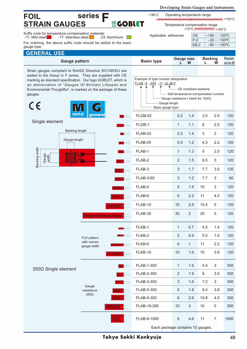
48
Developing Strain Gauges and Instruments
Suffix code for temperature compensation materials -11: Mild steel -17: Stainless steel -23: AluminiumFor ordering, the above suffix code should be added to the basic gauge type.
48
Developing Strain Gauges and Instruments
Backing length
Gauge length
FLK patternwith narrowgauge width
Gaugeresistance350Ω
Example of type number designation FLAB -5 -350 -11 -3LJB-F
FLGB-02 0.2 1.4 3.5 2.5 120
FLGB-1 1 1.1 6 2.5 120
FLAB-03 0.3 1.4 3 2 120
FLAB-05 0.5 1.2 4.3 2.2 120
FLAB-1 1 1.3 5 2.5 120
FLAB-2 2 1.5 6.5 3 120
FLAB-3 3 1.7 7.7 3.5 120
FLAB-3-60 3 1.2 7.7 3 60
FLAB-5 5 1.5 10 3 120
FLAB-6 6 2.2 11 4.3 120
FLAB-10 10 2.5 15.4 5 120
FLAB-30 30 2 35 5 120
FLKB-1 1 0.7 4.5 1.4 120
FLKB-2 2 0.9 5.5 1.5 120
FLKB-6 6 1 11 2.2 120
FLKB-10 10 1.6 15 3.8 120
FLAB-1-350 1 1.6 4.5 3 350
FLAB-2-350 2 1.9 6 3.5 350
FLAB-3-350 3 1.6 7.2 3 350
FLAB-5-350 5 1.8 9.4 3.8 350
FLAB-6-350 6 2.6 10.8 4.5 350
FLAB-10-350 10 3 16 5 350
FLAB-6-1000 6 4.6 11 7 1000
Gau
ge
wid
th
Self-temperature-compensation numberGaugeresistance(blankfor120Ω)
Basic gauge typeGauge length
Single element
CE compliant leadwire
Bac
king
wid
th
350ΩSingleelement
Strain gauges compliant toRoHS2Directive2011/65/EUareadded to the lineup in F series. They are supplied with CE marking as standard specification. Our logo GOBLET, which is an abbreviation of “Gauges Of Bri l l iant Lifespan and Environmental Thoughtful”, is marked on the package of these gauges.
general
Each package contains 10 gauges.
+100°C
Operating temperature range
+10°CTemperature compensation range
+150°C‒196°C
Applicable adhesives CN ‒196~+120ºCP-2 ‒30~+150ºCEB-2 ‒60~+150ºC
GENERAL USEGauge pattern Basic type Gauge size
L WBacking L W
Resist-ance Ω
FOIL STRAIN GAUGES
series F
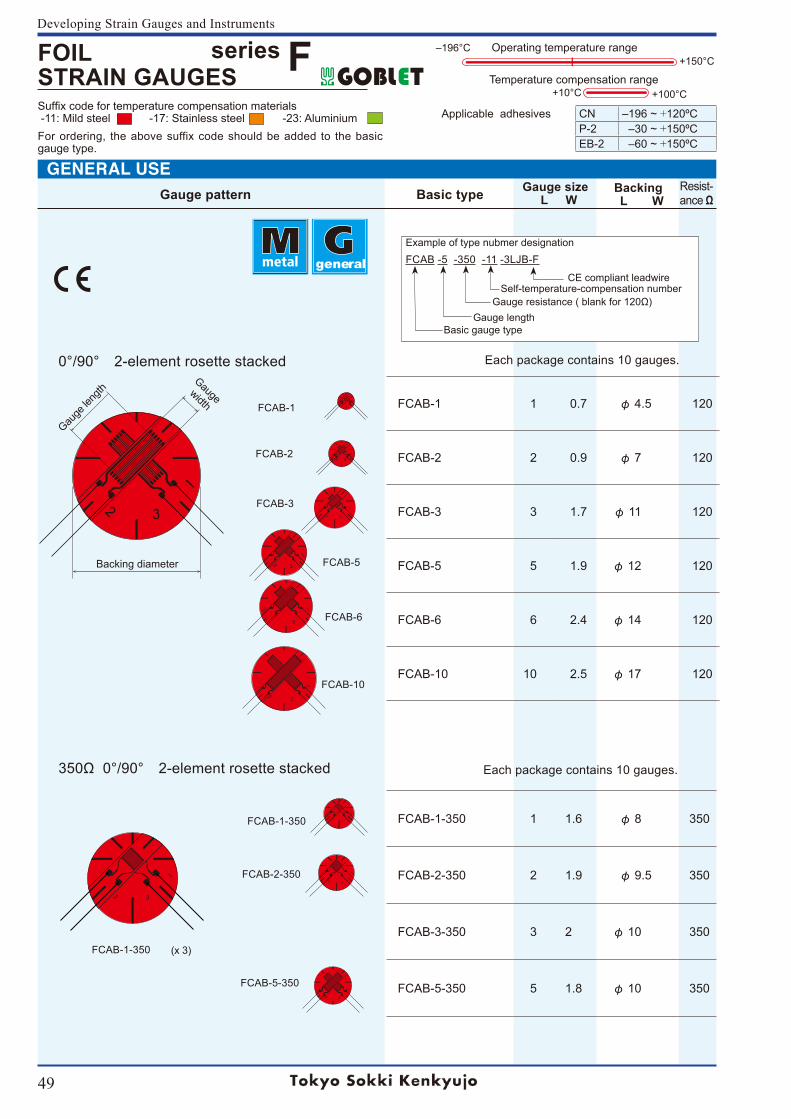
49
Developing Strain Gauges and Instruments
Suffix code for temperature compensation materials -11: Mild steel -17: Stainless steel -23: AluminiumFor ordering, the above suffix code should be added to the basic gauge type.
+100°C
Operating temperature range
+10°CTemperature compensation range
+150°C‒196°C
Applicable adhesives CN ‒196~+120ºCP-2 ‒30~+150ºCEB-2 ‒60~+150ºC
FOIL STRAIN GAUGES
series F
general
Gauge pattern Basic type Gauge size L W
Backing L W
Resist-ance Ω
FCAB-1 1 0.7 φ 4.5 120
FCAB-2 2 0.9 φ 7 120
FCAB-3 3 1.7 φ 11 120
FCAB-5 5 1.9 φ 12 120
FCAB-6 6 2.4 φ 14 120
FCAB-10 10 2.5 φ 17 120
Gauge
leng
thGauge
width
Backing diameter
Example of type nubmer designation FCAB -5 -350 -11 -3LJB-F
CE compliant leadwireSelf-temperature-compensation number
Gaugeresistance(blankfor120Ω)
Basic gauge typeGauge length
FCAB-1-350 1 1.6 φ 8 350
FCAB-2-350 2 1.9 φ 9.5 350
FCAB-3-350 3 2 φ 10 350
FCAB-5-350 5 1.8 φ 10 350
FCAB-1-350
FCAB-2-350
FCAB-5-350
(x 3)FCAB-1-350
FCAB-1
FCAB-2
FCAB-3
FCAB-5
FCAB-6
FCAB-10
Each package contains 10 gauges.
GENERAL USE
0°/90° 2-element rosette stacked
350Ω0°/90° 2-element rosette stacked
Each package contains 10 gauges.
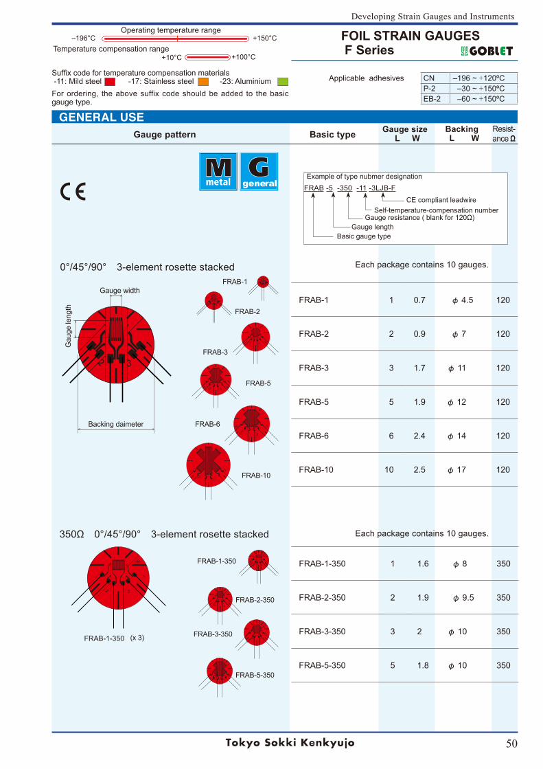
50
Developing Strain Gauges and Instruments
Suffix code for temperature compensation materials -11: Mild steel -17: Stainless steel -23: AluminiumFor ordering, the above suffix code should be added to the basic gauge type.
Operating temperature range
Temperature compensation range+150°C‒196°C
+10°C +100°C
general
FOIL STRAIN GAUGES F Series
FRAB-1
FRAB-2
FRAB-3
FRAB-5
FRAB-6
FRAB-10
Gauge width
Backing daimeter
350Ω 0°/45°/90° 3-element rosette stacked
FRAB-1-350 1 1.6 φ 8 350
FRAB-2-350 2 1.9 φ 9.5 350
FRAB-3-350 3 2 φ 10 350
FRAB-5-350 5 1.8 φ 10 350
(x 3)FRAB-1-350
FRAB-1 1 0.7 φ 4.5 120
FRAB-2 2 0.9 φ 7 120
FRAB-3 3 1.7 φ 11 120
FRAB-5 5 1.9 φ 12 120
FRAB-6 6 2.4 φ 14 120
FRAB-10 10 2.5 φ 17 120
Example of type nubmer designationFRAB -5 -350 -11 -3LJB-F
0°/45°/90° 3-element rosette stacked
Gau
ge le
ngth
Each package contains 10 gauges.
CE compliant leadwireSelf-temperature-compensation number
Gaugeresistance(blankfor120Ω)
Basic gauge typeGauge length
FRAB-5-350
FRAB-3-350
FRAB-2-350
FRAB-1-350
Each package contains 10 gauges.
Applicable adhesives CN ‒196~+120ºCP-2 ‒30~+150ºCEB-2 ‒60~+150ºC
Gauge pattern Basic type Gauge size L W
Backing L W
Resist-ance Ω
GENERAL USE
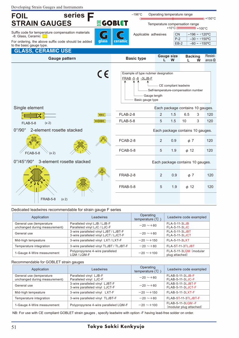
51
Developing Strain Gauges and Instruments
Suffix code for temperature compensation materials -8: Glass, Ceramic For ordering, the above suffix code should be added to the basic gauge type.
Gauge pattern Basic type Gauge size L W
Backing L W
Resist-ance Ω
FLAB-2-8 2 1.5 6.5 3 120
FLAB-5-8 5 1.5 10 3 120FLAB-5-8 (x 2)
FCAB-2-8 2 0.9 φ 7 120
FCAB-5-8 5 1.9 φ 12 120
FRAB-2-8 2 0.9 φ 7 120
FRAB-5-8 5 1.9 φ 12 120
FCAB-5-8 (x 2)
FRAB-5-8 (x 2)
Example of type nubmer designation FRAB -5 -8 -3LJB-F
Basic gauge type
CE compliant leadwire
0°/45°/90° 3-element rosette stacked
0°/90° 2-element rosette stacked
Single element
Each package contains 10 gauges.
Gauge length
Self-temperature-compensation number
Each package contains 10 gauges.
Each package contains 10 gauges.
Application Leadwires Operating temperature ( ) Leadwire code exampled
General use (temperature unchanged during measurement)
Paralleled vinyl LJB / LJB-FParalleled vinyl LJC / LJC-F -20 〜+80 FLA-5-11-3LJB
FLA-5-11-3LJC
General use 3-wire paralleled vinyl LJBT / LJBT-F3-wire paralleled vinyl LJCT / LJCT-F -20 〜+80 FLA-5-11-3LJBT
FLA-5-11-3LJCTMid-high tempeature 3-wire paralleled vinyl LXT / LXT-F -20 〜+150 FLA-5-11-3LXT
Temperature integration 3-wire paralleled vinyl TLJBT / TLJBT-F -20 〜+80 FLA-5T-11-3TLJBT
1-Gauge 4-Wire measurement Polypropyrene 4-wire paralleled LQM / LQM-F -20 〜+100 FLA-5-11-3LQM (modular
plug attached)
Recommendable for GOBLET strain gauges
Application Leadwires Operating temperature ( ) Leadwire code exampled
General use (temperature unchanged during measurement)
Paralleled vinyl LJB-FParalleled vinyl LJC-F -20 〜+80 FLAB-5-11-3LJB-F
FLAB-5-11-3LJC-F
General use 3-wire paralleled vinyl LJBT-F3-wire paralleled vinyl LJCT-F -20 〜+80 FLAB-5-11-3LJBT-F
FLAB-5-11-3LJCT-FMid-high tempeature 3-wire paralleled vinyl LXT-F -20 〜+150 FLAB-5-11-3LXT-F
Temperature integration 3-wire paralleled vinyl TLJBT-F -20 〜+80 FLAB-5T-11-3TLJBT-F
1-Gauge 4-Wire measurement Polypropyrene 4-wire paralleled LQM-F -20 〜+100 FLAB-5-11-3LQM -F(modular plug attached)
Dedicated leadwires recommendable for strain gauge F series
NB: For use with CE compliant GOBLET strain gauges , specify leadwire with option -F having lead-free solder on order.
+100°C
Operating temperature range
+10°CTemperature compensation range
+150°C‒196°C
Applicable adhesives CN ‒196~+120ºCP-2 ‒30~+150ºCEB-2 ‒60~+150ºC
FOIL STRAIN GAUGES
series F
GLASS, CERAMIC USE
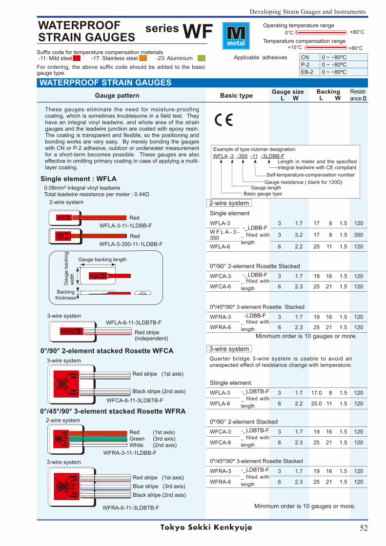
52
Developing Strain Gauges and Instruments
Suffix code for temperature compensation materials -11: Mild steel -17: Stainless steel -23: AluminiumFor ordering, the above suffix code should be added to the basic gauge type.
Operating temperature range+80°C
+80°C+10°C
0°C
Temperature compensation range
Applicable adhesives CN 0~+80ºCP-2 0~+80ºCEB-2 0~+80ºC
series WFWATERPROOFSTRAIN GAUGES
Gauge pattern Basic type Gauge size L W
Backing L W
Resist-ance Ω
These gauges eliminate the need for moisture-proofing coating,whichissometimestroublesomeinafieldtest.Theyhave an integral vinyl leadwire, and whole area of the strain gauges and the leadwire junction are coated with epoxy resin. Thecoatingistransparentandflexible,sothepositioningandbonding works are very easy. By merely bonding the gauges with CN or P-2 adhesive, outdoor or underwater measurement for a short-term becomes possible. These gauges are also effective in omitting primary coating in case of applying a multi-layer coating.
2-wire system
Single element : WFLA 0.08mm² integral vinyl leadwireTotalleadwireresistancepermeter:0.44Ω
3-wire systemWFLA-6-11-3LDBTB-F
WFLA-3-11-1LDBB-F
WFLA-3-350-11-1LDBB-F
2-wire system
3-wire system
Red stripe (1st axis)Blue stripe (3rd axis)Black stripe (2nd axis)
Red (1st axis)Green (3rd axis)White (2nd axis)
Red
Red
Red stripe(independent)
WFCA-6-11-3LDBTB-F
WFRA-6-11-3LDBTB-F
3-wire system
0°/45°/90° 3-element stacked Rosette WFRA
0°/90° 2-element stacked Rosette WFCA
Gauge backing length
Backing thickness
Gau
ge b
acki
ng
wid
th
Red stripe (1st axis) Black stripe (2nd axis)
WFRA-3-11-1LDBB-F
WFLA -3 -350 -11 -3LDBB-F Example of type nubmer designation
Basic gauge typeGauge length
Self-temperature-compensation numberGaugeresistance(blankfor120Ω)
Single elementWFLA-3
-_LDBB-F_ filled with length
3 1.7 17 8 1.5 120W F L A - 3 -350 3 3.2 17 8 1.5 350
WFLA-6 6 2.2 25 11 1.5 120
0°/90°2-elementRosetteStackedWFCA-3 -_LDBB-F
_ filled with length
3 1.7 19 16 1.5 120
WFCA-6 6 2.3 25 21 1.5 120
0°/45°/90° 3-element Rosette Stacked
WFRA-3 -LDBB-F_ filled with length
3 1.7 19 16 1.5 120
WFRA-6 6 2.3 25 21 1.5 120
SIingle elementWFLA-3 -_LDBTB-F
_ filled with length
3 1.7 17.0 8 1.5 120
WFLA-6 6 2.2 25.0 11 1.5 120
0°/90°2-elementStackedWFCA-3 -_LDBTB-F
_ filled with length
3 1.7 19 16 1.5 120
WFCA-6 6 2.3 25 21 1.5 120
0°/45°/90° 3-element Rosette Stacked
WFRA-3 -_LDBTB-F_ filled with length
3 1.7 19 16 1.5 120
WFRA-6 6 2.3 25 21 1.5 120
2-wire system
3-wire system
Minimum order is 10 gauges or more.
Minimum order is 10 gauges or more.
Quarter bridge 3-wire system is usable to avoid an unexpected effect of resistance change with temperature.
Length in meter and the specified integral leadwire with CE compliant
WATERPROOF STRAIN GAUGES
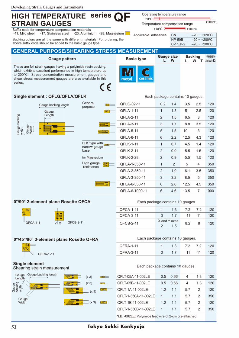
53
Developing Strain Gauges and Instruments
53
Suffixcodefortemperaturecompensationmaterials -11: Mild steel -17: Stainless steel -23: Aluminium -28: Magnesium
series QFHIGH TEMPERATURESTRAIN GAUGES
Applicable adhesives CN ‒20~+120ºCNP-50B ‒20~+200ºCC-1/EB-2 ‒20~+200ºC
Operating temperature range
+200°C‒20°C
+10°C +100°CTemperature compensation range
GENERAL PURPOSE/SHEARING STRESS MEASUREMENT
These are foil strain gauges having a polyimide resin backing, which exhibits excellent performance in high temperature up to 200°C. Stress concentration measurement gauges and shear stress measurement gauges are also available in this series.
0°/90° 2-element plane Rosette QFCA
Generalpurpose
QFLG-02-11 0.2 1.4 3.5 2.5 120
QFLA-1-11 1 1.3 5 2.5 120
QFLA-2-11 2 1.5 6.5 3 120
QFLA-3-11 3 1.7 8.8 3.5 120
QFLA-5-11 5 1.5 10 3 120
QFLA-6-11 6 2.2 12.5 4.3 120FLK type withnarrow gaugebase
QFLK-1-11 1 0.7 4.5 1.4 120
QFLK-2-11 2 0.9 5.5 1.5 120
for Magnesium QFLK-2-28 2 0.9 5.5 1.5 120High gauge resistance
QFLA-1-350-11 1 2 5 4 350
QFLA-2-350-11 2 1.9 6.1 3.5 350
QFLA-3-350-11 3 3.2 8.5 5 350
QFLA-6-350-11 6 2.6 12.5 4.5 350
QFLA-6-1000-11 6 4.6 13.5 7 1000
QFCA-1-11 1 1.3 7.2 7.2 120QFCA-3-11 3 1.7 11 11 120
QFCB-2-11X and Y axes
8.2 8 1202 1.5
QFRA-1-11 1 1.3 7.2 7.2 120
QFRA-3-11 3 1.7 11 11 120
QFLT-05A-11-002LE 0.5 0.66 4 1.3 120
QFLT-05B-11-002LE 0.5 0.66 4 1.3 120
QFLT-1A-11-002LE 1.2 1.1 5.7 2 120
QFLT-1-350A-11-002LE 1 1.1 5.7 2 350
QFLT-1B-11-002LE 1.2 1.1 5.7 2 120
QFLT-1-350B-11-002LE 1 1.1 5.7 2 350
QFCA-1-11
QFRA-1-11
QFCB-2-11
(x 3)
(x 3)
(x 3)
(x 3)
Single element : QFLG/QFLA/QFLK
Gauge Length
Gau
ge
Wid
th
Gau
ge b
acki
ng
wid
th
Gauge backing length
0°/45°/90° 3-element plane Rosette QFRA
Single elementShearing strain measurement
Gauge Length
Gauge Width
Gau
ge
back
ing
wid
th
Gauge backing length
Each package contains 10 gauges.
N.B. -002LE: Polyimide leadwire of 2-cm pre-attached
Each package contains 10 gauges.
Each package contains 10 gauges.
Each package contains 10 gauges.
Y X
Backing colors are all the same with different materials For ordering, the abovesuffixcodeshouldbeaddedtothebasicgaugetype.
Developing Strain Gauges and Instruments
Gauge pattern Basic type Gauge size L W
Backing L W T
Resist-ance Ω
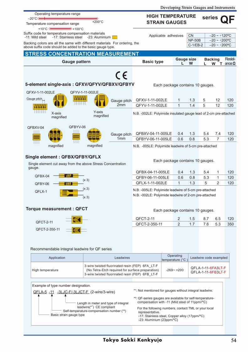
54
Developing Strain Gauges and Instruments
54
series QFHIGH TEMPERATURESTRAIN GAUGES
STRESS CONCENTRATION MEASUREMENTGauge pattern Basic type Gauge size
L WBacking
L W TResist-ance Ω
Suffixcodefortemperaturecompensationmaterials -11: Mild steel -17: Stainless steel -23: Aluminium
Backing colors are all the same with different materials For ordering, the abovesuffixcodeshouldbeaddedtothebasicgaugetype.
Operating temperature range
+200°C‒20°C
+10°C +100°CTemperature compensation range
Applicable adhesives CN ‒20~+120ºCNP-50B ‒20~+200ºCC-1/EB-2 ‒20~+200ºC
Example of type number designation.
QFLA-5 -11 -3LJC-F/-3LJCT-F (2-wire/3-wire)
Length in meter and type of integral leadwire(*1) CE compliant Self-temperature-compensation number (*²) Basic strain gauge type
*¹: Not mentioned for gauges without integral leadwire.
*²: QF-series gauges are available for self-temperature- compensation with -11 (Mild steel of 11ppm//°C)
For the following numbers, contact TML or your local representative.-17: Stainless steel, Copper alloy (17ppm/°C)-23: Aluminium (23ppm/°C)
Gauge pitch2mm
QFXV-1-11-002LE 1 1.3 5 12 120QFYV-1-11-002LE 1 1.4 5 12 120
QFBX-04-11-005LE 0.4 1.3 5.4 1 120QFBY-06-11-005LE 0.6 0.8 5.3 1 120QFLX-1-11-002LE 1 1.3 5 2 120
Gauge pitch1mm
QFBXV-04-11-005LE 0.4 1.3 5.4 7.4 120QFBYV-06-11-005LE 0.6 0.8 5.3 7 120
QFCT-2-11 2 1.5 8.7 6.5 120QFCT-2-350-11 2 1.7 7.6 5.3 350
(x 3)
(x 3)
(x 3)
5-element single-axis : QFXV/QFYV/QFBXV/QFBYV
N.B. -002LE: Polyimide insulated gauge lead of 2-cm pre-attached
Single element : QFBX/QFBY/QFLXSingle element cut away from the above Stress Concentration gauge.
N.B. -005LE: Polyimide leadwire of 5-cm pre-attachedN.B. -002LE: Polyimide leadwire of 2-cm pre-attached
QFBX-04
QFBY-06
QFLX-1
X-axis magnified
QFXV-1-11-002LE QFYV-1-11-002LE
Y-axis magnified
QFBXV-04 QFBYV-06
magnified magnified N.B. -005LE: Polyimide leadwire of 5-cm pre-attached
Torque measurement : QFCT
QFCT-2-11
QFCT-2-350-11
Each package contains 10 gauges.
Each package contains 10 gauges.
Each package contains 10 gauges.
Gauge pitch
Recommendable integral leadwire for QF series
Application Leadwires Operatingtemperature (°C ) Leadwire code exampled
High temperature3-wiretwistedfluorinatedresin(FEP)6FA_LT-F (No Tetra-Etch required for surface preparation)3-wiretwistedfluorinatedresin(FEP)6FB_LT-F
-269~+200 QFLA-1-11-6FA3LT-FQFLA-1-11-6FB3LT-F
Developing Strain Gauges and Instruments
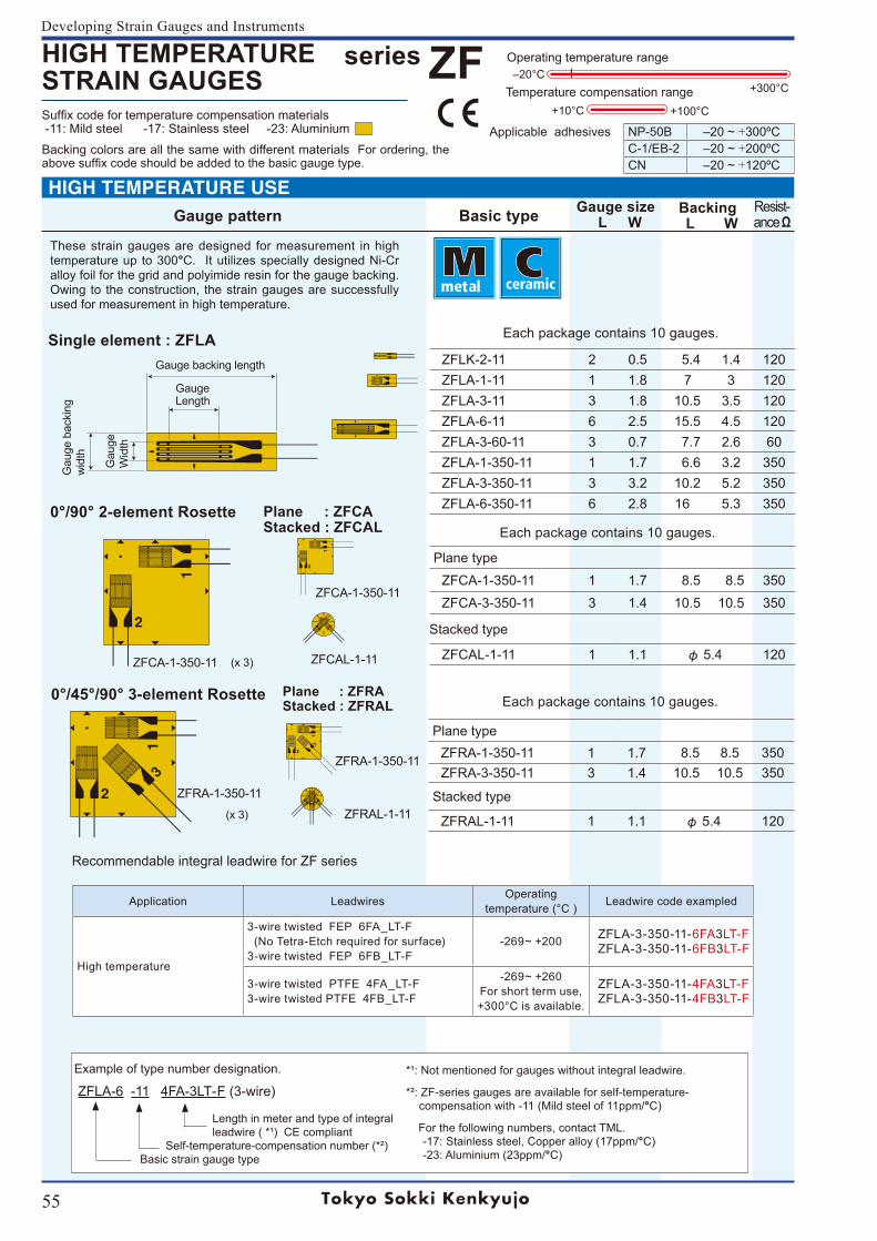
55
Developing Strain Gauges and Instruments
series ZFHIGH TEMPERATURESTRAIN GAUGES
These strain gauges are designed for measurement in high temperature up to 300°C. It utilizes specially designed Ni-Cr alloy foil for the grid and polyimide resin for the gauge backing. Owing to the construction, the strain gauges are successfully used for measurement in high temperature.
Operating temperature range
+300°C‒20°C
+10°C +100°CTemperature compensation range
Applicable adhesives NP-50B ‒20~+300ºCC-1/EB-2 ‒20~+200ºCCN ‒20~+120ºC
Example of type number designation.
ZFLA-6 -11 4FA-3LT-F (3-wire)
Length in meter and type of integral leadwire ( *¹) CE compliant Self-temperature-compensation number (*²) Basic strain gauge type
*¹: Not mentioned for gauges without integral leadwire.
*²: ZF-series gauges are available for self-temperature- compensation with -11 (Mild steel of 11ppm/°C)
For the following numbers, contact TML.-17: Stainless steel, Copper alloy (17ppm/°C)-23: Aluminium (23ppm/°C)
Suffixcodefortemperaturecompensationmaterials -11: Mild steel -17: Stainless steel -23: Aluminium
Backing colors are all the same with different materials For ordering, the abovesuffixcodeshouldbeaddedtothebasicgaugetype.
Recommendable integral leadwire for ZF series
Application Leadwires Operatingtemperature (°C ) Leadwire code exampled
High temperature
3-wiretwistedFEP6FA_LT-F (No Tetra-Etch required for surface)3-wiretwistedFEP6FB_LT-F
-269~+200 ZFLA-3-350-11-6FA3LT-FZFLA-3-350-11-6FB3LT-F
3-wire twisted PTFE 4FA_LT-F3-wire twisted PTFE 4FB_LT-F
-269~+260For short term use,+300°C is available.
ZFLA-3-350-11-4FA3LT-FZFLA-3-350-11-4FB3LT-F
ZFLK-2-11 2 0.5 5.4 1.4 120ZFLA-1-11 1 1.8 7 3 120ZFLA-3-11 3 1.8 10.5 3.5 120ZFLA-6-11 6 2.5 15.5 4.5 120ZFLA-3-60-11 3 0.7 7.7 2.6 60ZFLA-1-350-11 1 1.7 6.6 3.2 350ZFLA-3-350-11 3 3.2 10.2 5.2 350ZFLA-6-350-11 6 2.8 16 5.3 350
Plane typeZFCA-1-350-11 1 1.7 8.5 8.5 350ZFCA-3-350-11 3 1.4 10.5 10.5 350
Stacked type
ZFCAL-1-11 1 1.1 φ 5.4 120
Plane typeZFRA-1-350-11 1 1.7 8.5 8.5 350ZFRA-3-350-11 3 1.4 10.5 10.5 350
Stacked type
ZFRAL-1-11 1 1.1 φ 5.4 120
Gauge pattern Basic type Gauge size L W
Backing L W
Resist-ance Ω
(x 3)
(x 3)
0°/90° 2-element Rosette
Single element : ZFLA
0°/45°/90° 3-element Rosette
Plane : ZFCAStacked : ZFCAL
Plane : ZFRAStacked : ZFRAL
Gauge backing length
Gauge Length
Gau
ge
Wid
th
Gau
ge b
acki
ng
wid
th
ZFCA-1-350-11
ZFRA-1-350-11
ZFCAL-1-11ZFCA-1-350-11
ZFRA-1-350-11ZFRAL-1-11
Each package contains 10 gauges.
HIGH TEMPERATURE USE
Each package contains 10 gauges.
Each package contains 10 gauges.
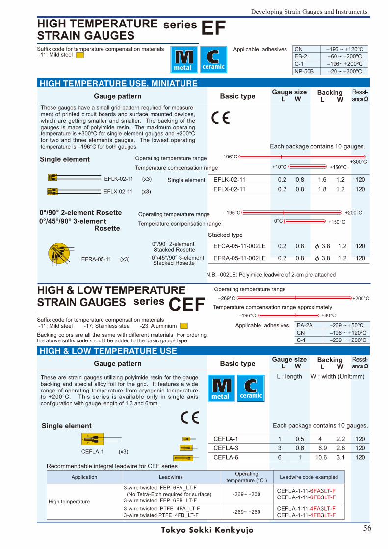
56
Developing Strain Gauges and Instruments
series EFHIGH TEMPERATURESTRAIN GAUGES
series CEFHIGH & LOW TEMPERATURESTRAIN GAUGES
Gauge pattern Basic type Gauge size L W
Backing L W
Resist-ance Ω
L : length W : width (Unit:mm)
These gauges have a small grid pattern required for measure-ment of printed circuit boards and surface mounted devices, which are getting smaller and smaller. The backing of the gauges is made of polyimide resin. The maximum operaing temperature is +300°C for single element gauges and +200°C for two and three elements gauges. The lowest operating temperatureis‒196°C for both gauges.
Applicable adhesives CN ‒196~+120ºCEB-2 ‒60~+200ºCC-1 ‒196~+200ºCNP-50B ‒20~+300ºC
Suffixcodefortemperaturecompensationmaterials -11: Mild steel
Operating temperature range +200°C‒196°C0°C +150°CTemperature compensation range
Operating temperature range+300°C
‒196°C
+10°C +150°CTemperature compensation range
Suffixcodefortemperaturecompensationmaterials -11: Mild steel -17: Stainless steel -23: AluminiumBacking colors are all the same with different materials For ordering, theabovesuffixcodeshouldbeaddedtothebasicgaugetype.
+200°C‒269°C
Operating temperature range
Temperature compensation range approximately+80°C‒196°C
These are strain gauges utilizing polyimide resin for the gauge backing and special alloy foil for the grid. It features a wide range of operating temperature from cryogenic temperature to +200°C. This series is available only in single axis configurationwithgaugelengthof1,3and6mm.
Applicable adhesives EA-2A ‒269~+50ºCCN ‒196~+120ºCC-1 ‒269~+200ºC
Recommendable integral leadwire for CEF series
Application Leadwires Operatingtemperature (°C ) Leadwire code exampled
High temperature
3-wiretwistedFEP6FA_LT-F (No Tetra-Etch required for surface)3-wiretwistedFEP6FB_LT-F
-269~+200 CEFLA-1-11-6FA3LT-FCEFLA-1-11-6FB3LT-F
3-wire twisted PTFE 4FA_LT-F3-wire twisted PTFE 4FB_LT-F -269~+260 CEFLA-1-11-4FA3LT-F
CEFLA-1-11-4FB3LT-F
EFLK-02-11 0.2 0.8 1.6 1.2 120EFLX-02-11 0.2 0.8 1.8 1.2 120
CEFLA-1 1 0.5 4 2.2 120CEFLA-3 3 0.6 6.9 2.8 120CEFLA-6 6 1 10.6 3.1 120
Stacked type
EFCA-05-11-002LE 0.2 0.8 φ 3.8 1.2 120
EFRA-05-11-002LE 0.2 0.8 φ 3.8 1.2 120
Gauge pattern Basic type Gauge size L W
Backing L W
Resist-ance Ω
EFLK-02-11 (x3)
Single element
0°/90° 2-element Rosette0°/45°/90° 3-element Rosette
EFLX-02-11 (x3)
EFRA-05-11 (x3)
CEFLA-1 (x3)
Single element
Each package contains 10 gauges.
Each package contains 10 gauges.
Single element
0°/90°2-element Stacked Rosette0°/45°/90°3-element Stacked Rosette
N.B. -002LE: Polyimide leadwire of 2-cm pre-attached
HIGH TEMPERATURE USE, MINIATURE
HIGH & LOW TEMPERATURE USE
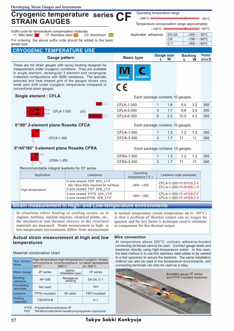
57
Developing Strain Gauges and Instruments
Suffix code for temperature compensation materials -11: Mild steel -17: Stainless steel -23: AluminiumFor ordering, the above suffix code should be added to the basic gauge type.
57
Developing Strain Gauges and Instruments
+80°C
+80°C‒196°C
Strain measurement in High- and Low-temperature environments
Recommendable integral leadwire for CF series
Application Leadwires Operatingtemperature (°C ) Leadwire code exampled
High temperature
3-wiretwistedFEP6FA_LT-F (No Tetra-Etch required for surface)3-wiretwistedFEP6FB_LT-F
-269~+200 CFLA-1-350-11-6FA3LT-FCFLA-1-350-11-6FB3LT-F
3-wire twisted PTFE 4FA_LT-F3-wire twisted PTFE 4FB_LT-F -269~+260 CFLA-1-350-11-4FA3LT-F
CFLA-1-350-11-4FB3LT-F
Gauge pattern Basic type Gauge size L W
Backing L W
Resist-ance Ω
series CFCryogenic temperatureSTRAIN GAUGES
Applicable adhesives EA-2A ‒269~+50ºCCN ‒196~+80ºCC-1 ‒269~+80ºC
‒269°C
Operating temperature range
Temperature compensation range approximately
CFLA-1-350 1 1.6 5.4 3.2 350CFLA-3-350 3 1.7 8.8 3.5 350CFLA-6-350 6 2.2 12.5 4.3 350
CFCA-1-350 1 1.3 7.2 7.2 350CFCA-3-350 3 1.7 11 11 350
CFRA-1-350 1 1.3 7.2 7.2 350CFRA-3-350 3 1.7 11 11 350
Test tempe-rature
High-temperature a tmosphere to 300°C
High-temperature atmosphere to 800°C
Cryogenic tempe-rature atmosphere to-269°C
Strain Gauge ZF series AWHU (Weldable type) CF series
Bonding adhesive NP-50B Resistance
welding EA-2A, C-1
Connecting terminals Not used - TPF
Leadwire PTFE-insulated MI cable FEP-insulatedCoating materials TSE3976-B - K-1
Material combination chart
Bondable gauge ZF seriesand PTFE insulated leadwires
Actual strain measurement at high and low temperatures
Wire connectionAt temperature above 200°C, ordinary adhesive-bonded connecting terminals cannot be used. Connect gauge leads and leadwires directly using high-temperature solder. In this case, the best method is to use thin stainless steel plates to be welded to a test specimen to secure the leadwire. The same installation method can also be used in low temperature environments, and connecting terminals can also be used as a relay.
in normal temperature (room temperature up to +80°C) in that a problem of thermal output can no longer be ignored, and the key factor is technique used to eliminate or compensate for this thermal output.
In situations where heating or cooling occurs, as in engines, turbines, nuclear reactors, chemical plants, etc., the mechanical and thermal stresses in the structural materials are measured. Strain measurement in high- or low-temperature environments differs from measurement
Each package contains 10 gauges.
Each package contains 10 gauges.
Each package contains 10 gauges.
0°/90° 2-element plane Rosette CFCA
These are foil strain gauges with epoxy backing designed for measurement under cryogenic conditions. They are available in single element, rectangular 2-element and rectangular 3-elementconfigurationswith350Ωresistance.Thespeciallyselected and heat treated grid of the gauges shows very small zero shift under cryogenic temperature compared to conventional strain gauges.
Single element : CFLA
0°/45°/90° 3-element plane Rosette CFRA
CFLA-1-350 (x3)
CFCA-1-350
CFRA-1-350
CRYOGENIC TEMPERATURE USE
PTFE:Polytetrafluoroethylene4FFEP:Tetrafluoroethylene-hexafluoropropylenecopolymer
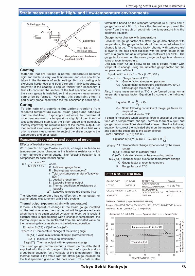
58
Developing Strain Gauges and Instruments
Strain measurement in High- and Low-temperature environments
GAUGE TYPE : FLA-3-11 TESTED ON : SS 400
LOT NO. : A502515 COEFFICIENT OF THERMAL EXPANSION : 11.8 x10⁻⁶/°C
GAUGE FACTOR : 2.14 ±1% TEMPERATURE COEFFICIENT OF G.F. :+0.1±0.05 %/10°C
ADHESIVE : P-2 DATA NO. : A0312
Measurement correction and causes of errors
6.0
4.0
2.0
0.0
-2.0
-4.0
-6.0
Thermal output
TemperaturecoefficientofGF
300
200
100
0
-100
-200
-3000 20 40 60 80A
PPA
RE
NT
STR
AIN
(
µ m
/m)
TEMPERATURE (°C)
Varia
tion
of G
.F. w
ith te
mpe
ratu
reTemperaturecoefficentofG
.F.(%
)
(Instrument G.F. set: 2.00) Apparent strain Gauge Factor
THERMALOUTPUT(Ɛapp:APPARENTSTRAIN)
Ɛapp=-2.94x101+2.32xT1-4.60x10⁻²xT2 +1.67x10⁻⁴ xT3+5.00x10⁻⁷xT4 (µ m/m)Tolerance : ±0.85 [ (µ m/m)/°C ], T : Temperature
CoatingMaterials that are flexible in normal temperature become rigid and brittle in very low temperature, and care should be taken in the thickness of such coatings. K-1 is a coating with excellent hardeness and peel strength in low temperature. However, if the coating is applied thicker than necessary, it tends to constrain the section of the test specimen on which the strain gauge is installed, so that accurate measurements cannot be performed. Note that this constraint effect is particularly pronounced when the test specimen is a thin plate.
CuringTo el iminate characterist ic f luctuations result ing from repeated temperature cycles, strain gauge and adhesive must be stabilized. Exposing an adhesive that hardens at room temperature to a temperature slightly higher than the test temperature stabilizes the strain gauge and adhesive, thereby improving the reproducibility of the thermal output. For mechanical structures, perform repeated break-in trial runs prior to strain measurement to subject the strain gauge to the temperature and other loads.
Effects of leadwire temperatureWith quarter bridge 2-wire system, changes in leadwire temperature cause changes in the leadwire resistance which in turn generate thermal output. The following equation is to compensate for such thermal output.
Ɛ=‒‒‒‒‒‒‒‒‒‒‒‒ where K : Indicated gauge factor R:Straingaugeresistance(Ω) r : Total resistance per meter of leadwire (Ω/m) L : Leadwire length (m) Ɛ:Leadwirethermaloutput α:Thermalcoefficientofresistanceof leadwire ΔT:Leadwiretemperaturechange(°C)The leadwire temperature has no effect on thermal output for quarter bridge measurement with 3-wire system.
rxLxαxΔTK x (R + r x L)
Thermal output (Apparent strain with temperature)If there is temperature change in the strain gauge installed on the test specimen, thermal output will be generated even when there is no strain caused by external force. As a result, if external force is applied along with a change in temperature, the thermal output must be subtracted from the indicated value on the measuring device as shown in the following equation.EquationƐc(ΔT)=Ɛ(ΔT)‒Ɛapp(ΔT) where ΔT:Temperaturechangeatthestraingauge Ɛc(ΔT):Valueminusthermaloutput(correctedvalue) Ɛ(ΔT):Indicatedvalueonstrainmeter Ɛapp(ΔT):ThermaloutputwithtemperaturechangeThe strain gauge thermal output is shown on the data sheet supplied with the strain gauge in the form of a graph and as a quadratic equation (as a variable of the temperature). This thermal output is the value with the strain gauge installed on the test specimen given on the data sheet. This data is also
formulated based on the standard temperature of 20°C and a gauge factor of 2.00. To check the thermal output, read the value from the graph or substitute the temperature into the quadratic equation.
Gauge factor change with temperatureBecause the gauge factor of a strain gauge also changes with temperature, the gauge factor should be corrected when this change is large. The gauge factor change with temperature is given in the data sheet supplied with the strain gauge in the formofagraphandasatemperaturecoefficientper10°C. The gauge factor shown on the strain gauge package is a reference value at room temperature. Use Equation KT as below to obtain a gauge factor with temperature change using the indicated gauge factor and the temperaturecoefficient. Equation KT=Kx1+CK x (t - 20) /10 Where KT : Gauge factor at T°C K : Gauge factor at room temperature CK:Gaugefactortemperaturecoefficient(%/10°C) T : Strain gauge temperature (°C)Also, in case measurement at T°C is performed using normal temperaturegauge factor,EquationƐG corrects the indicated value.
EquationƐG= KxƐT KT
ƐG : Strain following correction of the gauge factor for temperature ƐT : Indicated strain for T°CIf strain is measured when external force is applied at the same time as a temperature change, perform thermal output and gauge factor corrections described above. Use the following equation to correct the indicated strain on the measuring device and obtain the strain due to the external force.From Equations Ɛc(ΔT)andƐG,
EquationƐ(ΔT)=Ɛi (ΔT)‒Ɛapp(ΔT)x‒‒‒
Where ΔT:Temperaturechangeexperiencedbythestrain gauge Ɛ(ΔT):StrainduetoexternalforceƐi (ΔT):Indicatedstrainonthemeasuringdevice Ɛapp(ΔT):Thermaloutputduetothetemperaturechange K : Gauge factor at room temperature KT : Gauge factor at T °C
Soldering probe
Leadwires
Thin plate of stainless steel
Gauge leads and leadwires soldered directly
STRAIN GAUGE TEST DATA
KKT
Tip
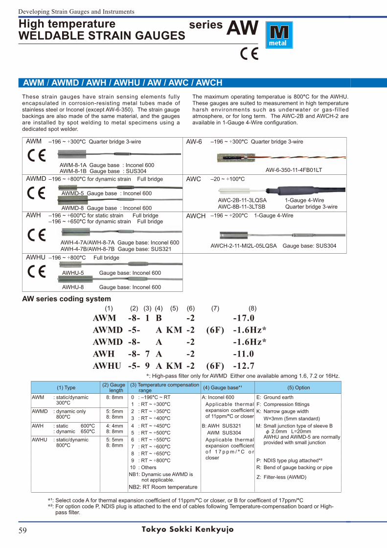
59
Developing Strain Gauges and Instruments
AWM ‒196~+300°C Quarter bridge 3-wire AW-6 ‒196~+300°C Quarter bridge 3-wire
AWM-8-1AGaugebase:Inconel600AWM-8-1B Gauge base : SUS304 AW-6-350-11-4FB01LT
AWMD ‒196~+800°C for dynamic strain Full bridge AWC ‒20~+100°C
AWMD-5 Gaugebase:Inconel600
AWMD-8 Gaugebase:Inconel600 AWC-2B-11-3LQSA 1-Gauge 4-Wire AWC-8B-11-3LTSB Quarter bridge 3-wire
AWH ‒196~+600°C for static strain Full bridge‒196~+650°C for dynamic strain Full bridge
AWCH ‒196~+200°C 1-Gauge 4-Wire
AWH-4-7A/AWH-8-7AGaugebase:Inconel600 AWH-4-7B/AWH-8-7B Gauge base: SUS321 AWCH-2-11-MI2L-05LQSA Gauge base: SUS304
AWHU ‒196~+800°C Full bridge AWHU-5Gaugebase:Inconel600
AWHU-8Gaugebase:Inconel600
AWM / AWMD / AWH / AWHU / AW / AWC / AWCH
(1) (2) (3) (4) (5) (6) (7) (8)AWM -8- 1 B -2 -17.0AWMD -5- A KM -2 (6F) -1.6Hz*AWMD -8- A -2 -1.6Hz*AWH -8- 7 A -2 -11.0AWHU -5- 9 A KM -2 (6F) -12.7
High temperature WELDABLE STRAIN GAUGES
series AW
(1) Type (2) Gauge length
(3) Temperature compensation range (4) Gauge base*¹ (5) Option
AWM : static/dynamic 300°C
8: 8mm 0 :‒196°C~RT A:Inconel600 E: Ground earth1 :RT~+300°C Applicable thermal
expansioncoefficientof 11ppm/°C or closer
F: CompressionfittingsAWMD : dynamic only
800°C 5: 5mm 8: 8mm
2 :RT~+350°C K: Narrow gauge width3 :RT~+400°C W=3mm(5mmstandard)
AWH :static600°C:dynamic650°C
4: 4mm 8: 8mm
4 :RT~+450°C B: AWH SUS321 M: Small junction type of sleeve B φ2.0mmL=20mmAWHU and AWMD-5 are normally provided with small junction
5 :RT~+500°C AWM SUS304AWHU : static/dynamic
800°C 5: 5mm 8: 8mm
6 :RT~+550°C Applicable thermal expansioncoefficiento f 1 7 p p m / ° C o r closer
7 :RT~+600°C8 :RT~+650°C9 :RT~+800°C P: NDIS type plug attached*²10 : Others R: Bend of gauge backing or pipeNB1: Dynamic use AWMD is not applicable. Z: Filter-less (AWMD)
NB2: RT Room temperature
These strain gauges have strain sensing elements fully encapsulated in corrosion-resisting metal tubes made of stainlesssteelorInconel(exceptAW-6-350).Thestraingaugebackings are also made of the same material, and the gauges are installed by spot welding to metal specimens using a dedicated spot welder.
The maximum operating temperatue is 800°C for the AWHU. These gauges are suited to measurement in high temperature harsh environments such as underwater or gas-f i l led atmosphere, or for long term. The AWC-2B and AWCH-2 are availablein1-Gauge4-Wireconfiguration.
AW series coding system
*:High-passfilteronlyforAWMDEitheroneavailableamong1.6,7.2or16Hz.
*¹:SelectcodeAforthermalexpansioncoefficientof11ppm/°Corcloser,orBforcoefficentof17ppm/°C*²: For option code P, NDIS plug is attached to the end of cables following Temperature-compensation board or High-passfilter.
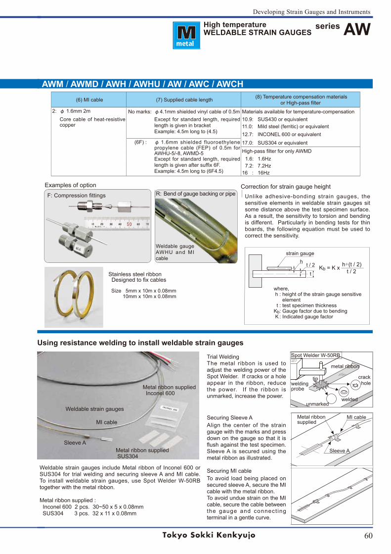
60
Developing Strain Gauges and Instruments
AWM / AWMD / AWH / AWHU / AW / AWC / AWCH
High temperature WELDABLE STRAIN GAUGES
series AW
(6)MIcable (7) Supplied cable length (8) Temperature compensation materialsorHigh-passfilter
2: φ1.6mm2m No marks: φ 4.1mm shielded vinyl cable of 0.5m Materials available for temperature-compensationCore cable of heat-resistive copper
Except for standard length, required length is given in bracketExample: 4.5m long to (4.5)
10.9: SUS430 or equivalent11.0: Mild steel (ferritic) or equivalent12.7: INCONEL600orequivalent
(6F): φ1.6mmshielded fluoroethylenepropylene cable (FEP) of 0.5m for AWHU-5/-8, AWMD-5Except for standard length, required lengthisgivenaftersuffix6F.Example:4.5mlongto(6F4.5)
17.0: SUS304 or equivalentHigh-passfilterforonlyAWMD1.6: 1.6Hz7.2: 7.2Hz
16: 16Hz
Metal ribbon suppliedInconel600
Weldable strain gauges
Metal ribbon supplied SUS304
MI cable
Sleeve A
Examples of option
F:CompressionfittingsCorrection for strain gauge height
Unlike adhesive-bonding strain gauges, the sensitive elements in weldable strain gauges sit some distance above the test specimen surface. As a result, the sensitivity to torsion and bending is different. Particularly in bending tests for thin boards, the following equation must be used to correct the sensitivity.
Kb=Kx————h+(t / 2) t / 2
t / 2hstrain gauge
Securing Sleeve AAlign the center of the strain gauge with the marks and press down on the gauge so that it is flushagainstthetestspecimen.Sleeve A is secured using the metal ribbon as illustrated.
Securing MI cableTo avoid load being placed on secured sleeve A, secure the MI cable with the metal ribbon.To avoid undue strain on the MI cable, secure the cable between the gauge and connect ing terminal in a gentle curve.
Sleeve A
MI cableMetal ribbonsupplied
t
Using resistance welding to install weldable strain gauges
Weldablestraingauges includeMetal ribbonof Inconel600orSUS304 for trial welding and securing sleeve A and MI cable. To install weldable strain gauges, use Spot Welder W-50RB together with the metal ribbon.
Metal ribbon supplied : Inconel6002pcs.30~50x5x0.08mm SUS304 3 pcs. 32 x 11 x 0.08mm
Trial WeldingThe metal ribbon is used to adjust the welding power of the Spot Welder. If cracks or a hole appear in the ribbon, reduce the power. If the ribbon is unmarked, increase the power.
Spot Welder W-50RB
weldingprobe
metal ribbon
tip crack hole
unmarkedwelded
where, h : height of the strain gauge sensitive element t : test specimen thicknessKb: Gauge factor due to bending K : Indicated gauge factor
Weldable gauge AWHU and MI cable
R: Bend of gauge backing or pipe
Stainless steel ribbon Designedtofixcables
Size 5mm x 10m x 0.08mm 10mm x 10m x 0.08mm
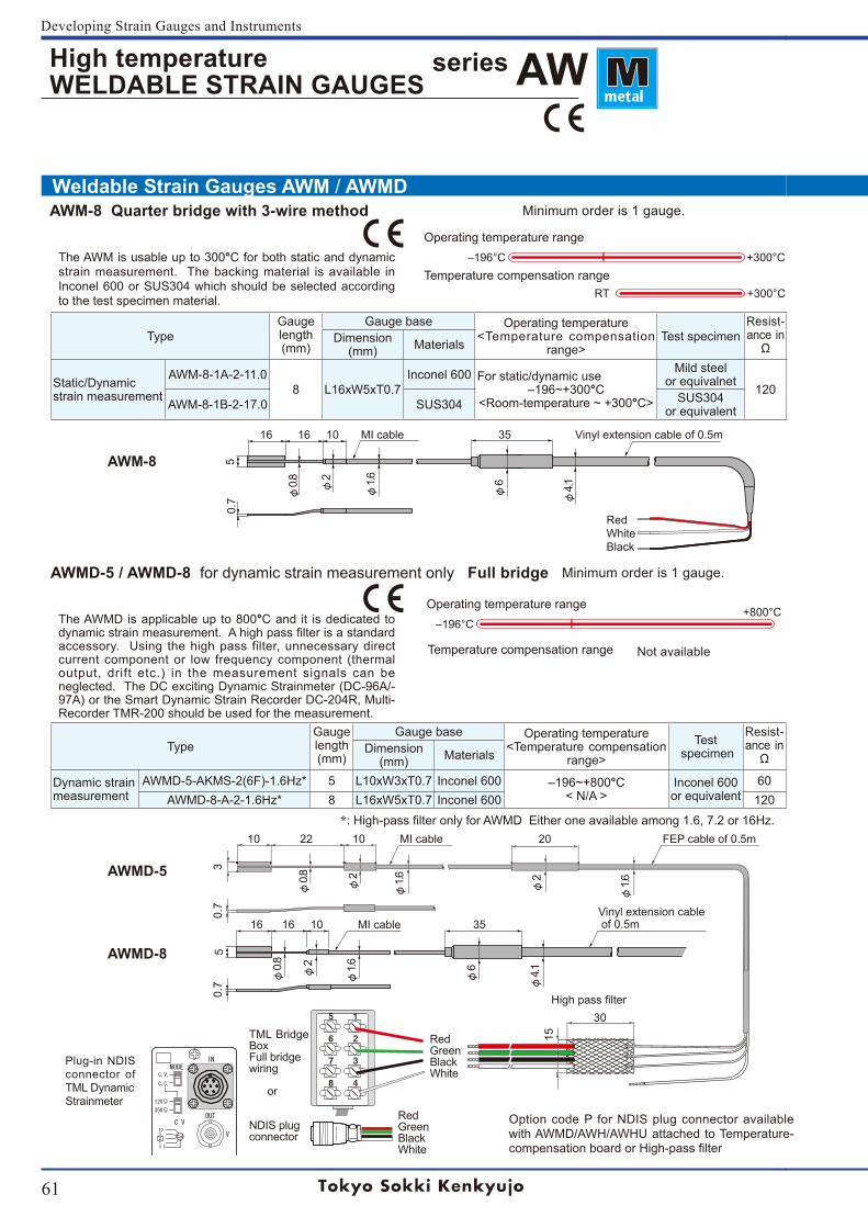
61
Developing Strain Gauges and Instruments
5
6
7
8
1
2
3
4
W
Operating temperature range+800°C
‒196°C
TypeGaugelength(mm)
Gauge base Operating temperature<Temperature compensation
range>Test
specimen
Resist-ance in
ΩDimension
(mm) Materials
Dynamic strainmeasurement
AWMD-5-AKMS-2(6F)-1.6Hz* 5 L10xW3xT0.7 Inconel600 ‒196~+800°C< N/A >
Inconel600or equivalent
60AWMD-8-A-2-1.6Hz* 8 L16xW5xT0.7 Inconel600 120
Temperature compensation range Not available
+300°C‒196°C
TypeGaugelength(mm)
Gauge base Operating temperature<Temperature compensation
range>Test specimen
Resist-ance in Ω
Dimension(mm) Materials
Static/Dynamicstrain measurement
AWM-8-1A-2-11.08 L16xW5xT0.7
Inconel600 For static/dynamic use‒196~+300°C
<Room-temperature~+300°C>
Mild steel or equivalnet
120AWM-8-1B-2-17.0 SUS304 SUS304
or equivalent
RT +300°CTemperature compensation range
Weldable Strain Gauges AWM / AWMD
Operating temperature range
High temperature WELDABLE STRAIN GAUGES
series AW
*:High-passfilteronlyforAWMDEitheroneavailableamong1.6,7.2or16Hz.10 22 10 MI cable 20 FEP cable of 0.5m
5
φ0.8 φ2
φ1.6 φ2
φ4.1
0.7
RedGreenBlackWhite
3
φ1.6
161610MIcable 35Vinyl extension cable of 0.5m
φ0.8 φ2
φ1.6
0.7
RedGreenBlackWhite
TML Bridge Box Full bridgewiring
or
NDIS plugconnector
Plug-in NDIS connector of TML DynamicStrainmeter
φ6
Highpassfilter
Option code P for NDIS plug connector available with AWMD/AWH/AWHU attached to Temperature-compensationboardorHigh-passfilter
15
30
The AWMD is applicable up to 800°C and it is dedicated to dynamicstrainmeasurement.Ahighpassfilterisastandardaccessory. Using the high pass filter, unnecessary direct current component or low frequency component (thermal output, drift etc.) in the measurement signals can be neglected.TheDCexcitingDynamicStrainmeter(DC-96A/-97A)ortheSmartDynamicStrainRecorderDC-204R,Multi-Recorder TMR-200 should be used for the measurement.
161610MIcable 35 Vinylextensioncableof0.5m
5
φ0.8 φ
2
φ1.6
φ6
φ4.1
0.7
RedWhiteBlack
The AWM is usable up to 300°C for both static and dynamic strain measurement. The backing material is available in Inconel600orSUS304whichshouldbeselectedaccordingto the test specimen material.
AWM-8 Quarter bridge with 3-wire method Minimum order is 1 gauge.
AWMD-5 / AWMD-8 for dynamic strain measurement only Full bridge Minimum order is 1 gauge.
AWM-8
AWMD-5
AWMD-8
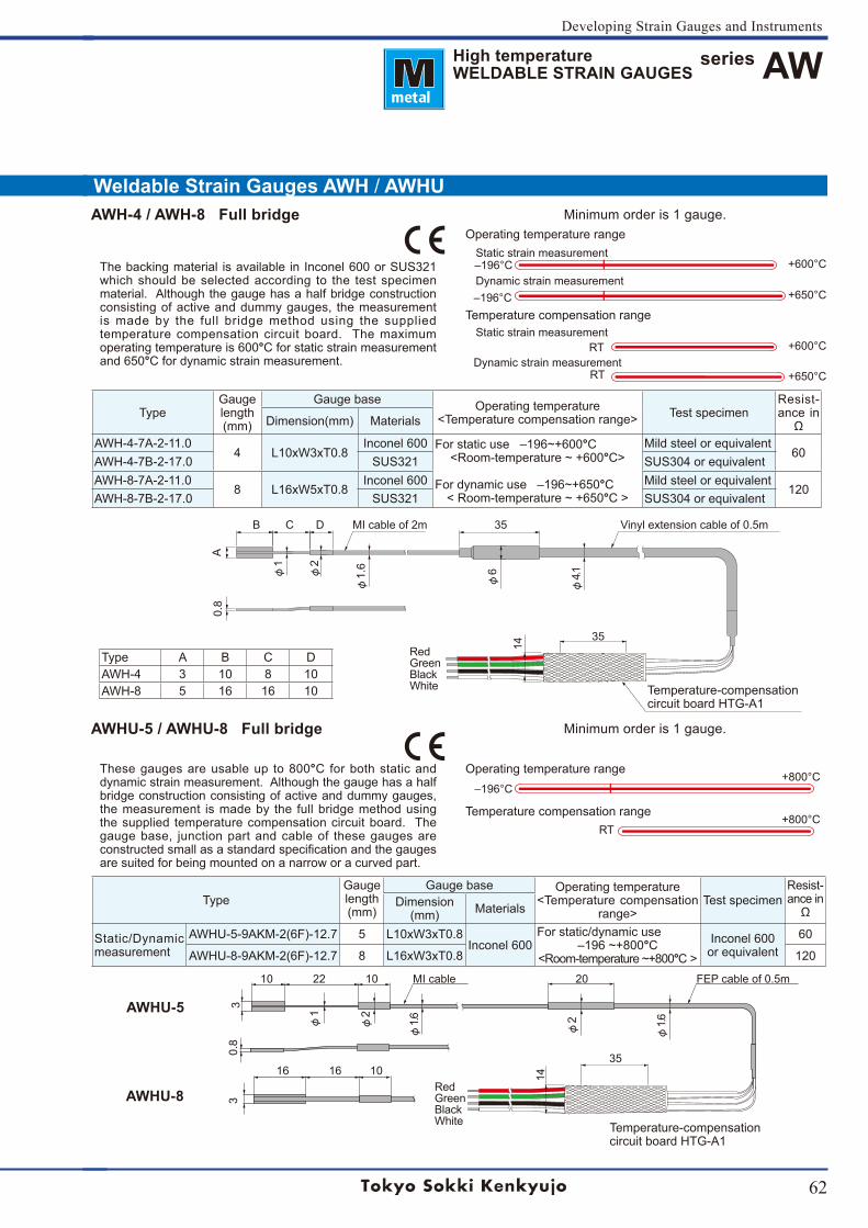
62
Developing Strain Gauges and Instruments
series AW
Weldable Strain Gauges AWH / AWHU
RT
RTC
RTC
Operating temperature range+800°C
‒196°C
Temperature compensation range+800°C
RT
TypeGaugelength(mm)
Gauge base Operating temperature<Temperature compensation
range>Test specimen
Resist-ance in Ω
Dimension(mm) Materials
Static/Dynamic measurement
AWHU-5-9AKM-2(6F)-12.7 5 L10xW3xT0.8Inconel600
For static/dynamic use‒196~+800°C
<Room-temperature~+800°C >Inconel600or equivalent
60
AWHU-8-9AKM-2(6F)-12.7 8 L16xW3xT0.8 120
Type A B C DAWH-4 3 10 8 10AWH-8 5 16 16 10
Operating temperature range
+600°C‒196°CStatic strain measurement
+650°C‒196°CDynamic strain measurement
Temperature compensation range
+600°CStatic strain measurement
+650°CRTDynamic strain measurement
TypeGaugelength(mm)
Gauge base Operating temperature<Temperature compensation range> Test specimen
Resist-ance in
ΩDimension(mm) Materials
AWH-4-7A-2-11.04 L10xW3xT0.8
Inconel600 Forstaticuse‒196~+600°C<Room-temperature~+600°C>
Fordynamicuse‒196~+650°C<Room-temperature~+650°C >
Mild steel or equivalent60
AWH-4-7B-2-17.0 SUS321 SUS304 or equivalentAWH-8-7A-2-11.0
8 L16xW5xT0.8Inconel600 Mild steel or equivalent
120AWH-8-7B-2-17.0 SUS321 SUS304 or equivalent
High temperature WELDABLE STRAIN GAUGES
10 22 10 MI cable 20 FEP cable of 0.5m
3
φ1
φ2
φ1.6
φ2
0.8
3
φ1.6
35
14
RedGreenBlackWhite
16 1610
Temperature-compensation circuit board HTG-A1
φ4.1
φ1.6
φ6φ
2
φ1
B C D MI cable of 2m 35 Vinyl extension cable of 0.5m
A0.
8
RedGreenBlackWhite
35
14
Temperature-compensation circuit board HTG-A1
These gauges are usable up to 800°C for both static and dynamic strain measurement. Although the gauge has a half bridge construction consisting of active and dummy gauges, the measurement is made by the full bridge method using the supplied temperature compensation circuit board. The gauge base, junction part and cable of these gauges are constructedsmallasastandardspecificationandthegaugesare suited for being mounted on a narrow or a curved part.
Thebackingmaterial isavailable inInconel600orSUS321which should be selected according to the test specimen material. Although the gauge has a half bridge construction consisting of active and dummy gauges, the measurement is made by the full bridge method using the supplied temperature compensation circuit board. The maximum operatingtemperatureis600°C for static strain measurement and650°C for dynamic strain measurement.
AWH-4 / AWH-8 Full bridge Minimum order is 1 gauge.
AWHU-5 / AWHU-8 Full bridge Minimum order is 1 gauge.
AWHU-5
AWHU-8
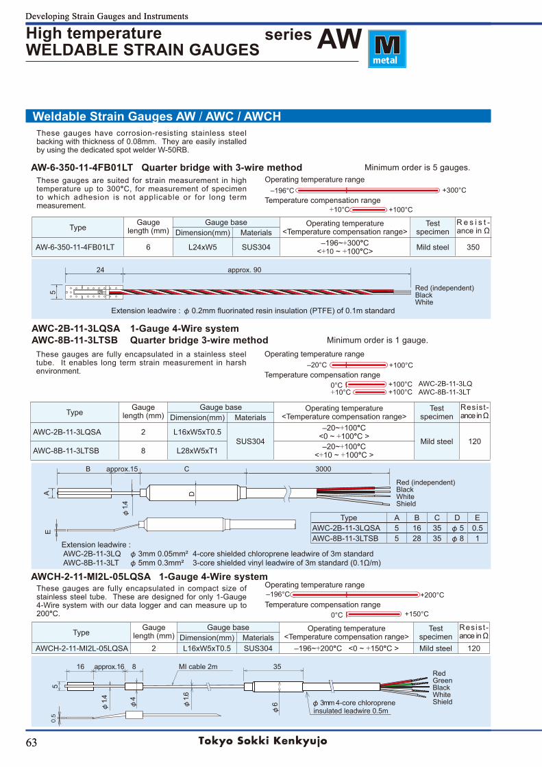
63
Developing Strain Gauges and Instruments
63
Developing Strain Gauges and Instruments
+100°C+100°C
Weldable Strain Gauges AW / AWC / AWCH
0.5
TypeGauge
length (mm)Gauge base Operating temperature
<Temperature compensation range>Test
specimenResis t -anceinΩDimension(mm) Materials
AWCH-2-11-MI2L-05LQSA 2 L16xW5xT0.5 SUS304 ‒196~+200°C<0~+150°C > Mild steel 120
Operating temperature range+300°C‒196°C
+100°C+10°CTemperature compensation range
TypeGauge
length (mm)Gauge base Operating temperature
<Temperature compensation range>Test
specimenR e s i s t -anceinΩDimension(mm) Materials
AW-6-350-11-4FB01LT 6 L24xW5 SUS304 ‒196~+300°C<+10~+100°C> Mild steel 350
Operating temperature range+100°C‒20°C
0°CTemperature compensation range
+10°CAWC-2B-11-3LQAWC-8B-11-3LT
TypeGauge
length (mm)Gauge base Operating temperature
<Temperature compensation range>Test
specimenResist-anceinΩDimension(mm) Materials
AWC-2B-11-3LQSA 2 L16xW5xT0.5SUS304
‒20~+100°C<0~+100°C >
Mild steel 120AWC-8B-11-3LTSB 8 L28xW5xT1 ‒20~+100°C
<+10~+100°C >
Operating temperature range+200°C‒196°C
+150°C0°CTemperature compensation range
Type A B C D EAWC-2B-11-3LQSA 5 16 35 φ5 0.5AWC-8B-11-3LTSB 5 28 35 φ8 1
series AWHigh temperature WELDABLE STRAIN GAUGES
Extension leadwire : AWC-2B-11-3LQ φ3mm 0.05mm² 4-core shielded chloroprene leadwire of 3m standard AWC-8B-11-3LT φ5mm 0.3mm² 3-core shielded vinyl leadwire of 3m standard (0.1Ω/m)
D
B approx.15 C 3000
A
φ1.4
16approx.168 MIcable2m 35
5
φ1.4 φ4
φ1.6
φ6
Red GreenBlackWhiteShieldφ3mm 4-core chloroprene
insulated leadwire 0.5m
These gauges have corrosion-resisting stainless steel backing with thickness of 0.08mm. They are easily installed by using the dedicated spot welder W-50RB.
Extension leadwire : φ0.2mmfluorinatedresininsulation(PTFE)of0.1mstandard
AW-6-350-11-4FB01LT Quarter bridge with 3-wire method Minimum order is 5 gauges.These gauges are suited for strain measurement in high temperature up to 300°C, for measurement of specimen to which adhesion is not applicable or for long term measurement.
24 approx.90
5 Red (independent)BlackWhite
AWC-2B-11-3LQSA 1-Gauge 4-Wire systemAWC-8B-11-3LTSB Quarter bridge 3-wire method Minimum order is 1 gauge.
These gauges are fully encapsulated in a stainless steel tube. It enables long term strain measurement in harsh environment.
AWCH-2-11-MI2L-05LQSA 1-Gauge 4-Wire systemThese gauges are fully encapsulated in compact size of stainless steel tube. These are designed for only 1-Gauge 4-Wire system with our data logger and can measure up to 200°C.
Red (independent)BlackWhiteShield
E
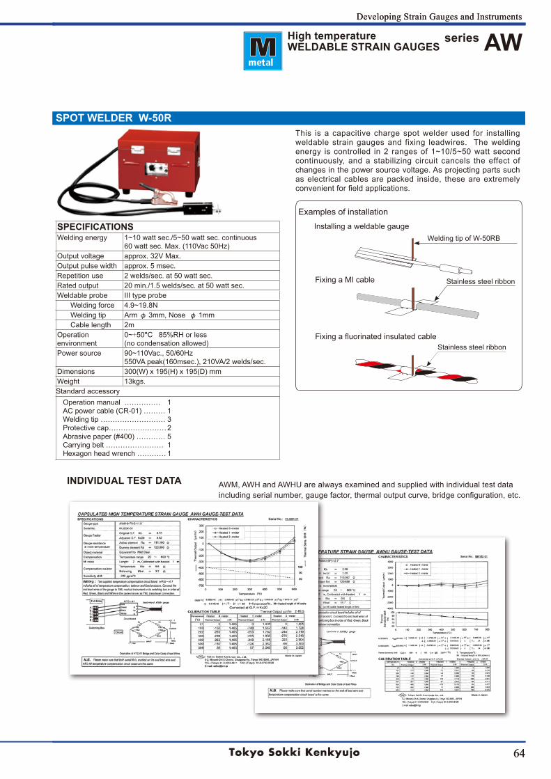
64
Developing Strain Gauges and Instruments
64
Developing Strain Gauges and Instruments
SPOT WELDER W-50R
Operation manual …………… 1AC power cable (CR-01) ……… 1Welding tip ……………………… 3Protective cap…………………… 2Abrasive paper (#400) ………… 5Carrying belt …………………… 1Hexagon head wrench ………… 1
series AW
SPECIFICATIONSWelding energy 1~10wattsec./5~50wattsec.continuous
60wattsec.Max.(110Vac50Hz)Output voltage approx. 32V Max.Output pulse width approx. 5 msec.Repetition use 2 welds/sec. at 50 watt sec.Rated output 20 min./1.5 welds/sec. at 50 watt sec.Weldable probe III type probe
Welding force 4.9~19.8NWelding tip Arm φ 3mm, Nose φ 1mmCable length 2m
Operation environment
0~+50°C 85%RH or less (no condensation allowed)
Power source 90~110Vac.,50/60Hz550VApeak(160msec.),210VA/2welds/sec.
Dimensions 300(W)x195(H)x195(D)mmWeight 13kgs.Standard accessory
High temperature WELDABLE STRAIN GAUGES
INDIVIDUAL TEST DATA AWM, AWH and AWHU are always examined and supplied with individual test data includingserialnumber,gaugefactor,thermaloutputcurve,bridgeconfiguration,etc.
This is a capacitive charge spot welder used for installing weldable strain gauges and fixing leadwires. The welding energy iscontrolled in2 rangesof1~10/5~50watt secondcontinuously, and a stabilizing circuit cancels the effect of changes in the power source voltage. As projecting parts such as electrical cables are packed inside, these are extremely convenientforfieldapplications.
Welding tip of W-50RB
Examples of installation
Stainless steel ribbon
Stainless steel ribbon
Installing a weldable gauge
Fixing a MI cable
Fixingafluorinatedinsulatedcable
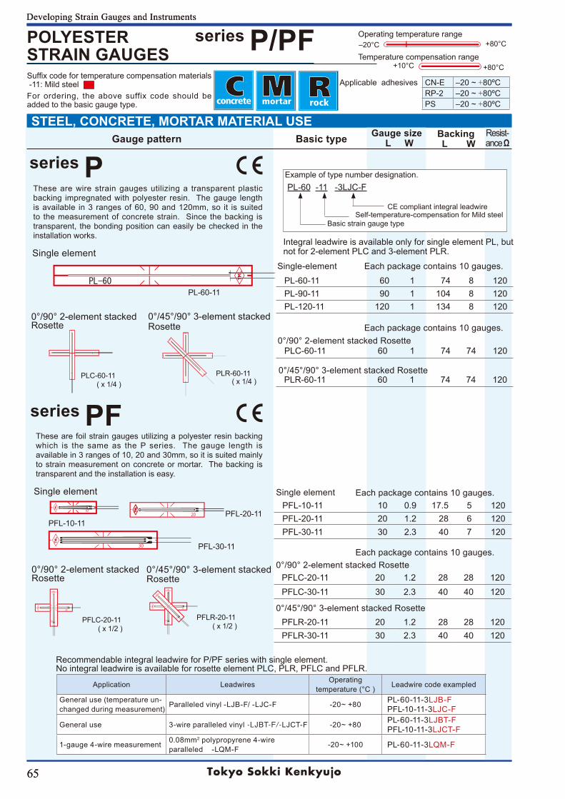
65
Developing Strain Gauges and Instruments
65
Developing Strain Gauges and Instruments
PL-60-11
series PF
1020
30
20
2020
20
20
STEEL, CONCRETE, MORTAR MATERIAL USE
Recommendable integral leadwire for P/PF series with single element. No integral leadwire is available for rosette element PLC, PLR, PFLC and PFLR.
Application Leadwires Operatingtemperature (°C ) Leadwire code exampled
General use (temperature un-changed during measurement) Paralleled vinyl -LJB-F/ -LJC-F -20~+80 PL-60-11-3LJB-F
PFL-10-11-3LJC-F
General use 3-wire paralleled vinyl -LJBT-F/-LJCT-F -20~+80 PL-60-11-3LJBT-FPFL-10-11-3LJCT-F
1-gauge 4-wire measurement 0.08mm2 polypropyrene 4-wire paralleled -LQM-F -20~+100 PL-60-11-3LQM-F
Integral leadwire is available only for single element PL, but not for 2-element PLC and 3-element PLR.
PL-60-11 60 1 74 8 120PL-90-11 90 1 104 8 120PL-120-11 120 1 134 8 120
PLC-60-11 60 1 74 74 120
PLR-60-11 60 1 74 74 120
PFL-10-11 10 0.9 17.5 5 120PFL-20-11 20 1.2 28 6 120PFL-30-11 30 2.3 40 7 120
PFLC-20-11 20 1.2 28 28 120PFLC-30-11 30 2.3 40 40 120
PFLR-20-11 20 1.2 28 28 120PFLR-30-11 30 2.3 40 40 120
Gauge pattern Basic type Gauge size L W
Backing L W
Resist-ance Ω
POLYESTER STRAIN GAUGES
series P/PF +80°C
+80°C+10°C
‒20°C
Temperature compensation range
Operating temperature range
Applicable adhesives CN-E ‒20~+80ºCRP-2 ‒20~+80ºCPS ‒20~+80ºC
Suffixcodefortemperaturecompensationmaterials -11: Mild steel For ordering, the above suffix code should be added to the basic gauge type.
0°/45°/90°3-elementstackedRosette
Single element
Single element
0°/90°2-elementstackedRosette
series P
Each package contains 10 gauges.
These are wire strain gauges utilizing a transparent plastic backing impregnated with polyester resin. The gauge length isavailable in3 rangesof60,90and120mm,so it issuitedto the measurement of concrete strain. Since the backing is transparent, the bonding position can easily be checked in the installation works.
Each package contains 10 gauges.
0°/90°2-elementstackedRosette
0°/45°/90°3-elementstackedRosette
PLC-60-11 ( x 1/4 )
PLR-60-11 ( x 1/4 )
PFLR-20-11 ( x 1/2 )
Single element
These are foil strain gauges utilizing a polyester resin backing which is the same as the P series. The gauge length is available in 3 ranges of 10, 20 and 30mm, so it is suited mainly to strain measurement on concrete or mortar. The backing is transparent and the installation is easy.
0°/90°2-elementstackedRosette
0°/45°/90°3-elementstacked Rosette
PFL-10-11
PFLC-20-11 ( x 1/2 )
PFL-20-11
PFL-30-11
0°/90°2-elementstackedRosette
0°/45°/90°3-elementstackedRosette
Single-element
Each package contains 10 gauges.
Example of type number designation. PL-60 -11 -3LJC-F CE compliant integral leadwire Self-temperature-compensation for Mild steel Basic strain gauge type
Each package contains 10 gauges.
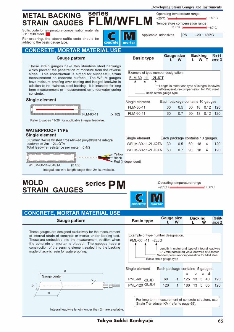
66
Developing Strain Gauges and Instruments
66
Developing Strain Gauges and Instruments
METAL BACKING STRAIN GAUGES
series FLM/WFLM
MOLD STRAIN GAUGES
series PM
Gauge pattern Basic type Gauge size L W
Backing L W
Resist-ance Ω
FLM-60-11 (x1/2)
+60°C‒20°COperating temperature range
a b c d
CONCRETE, MORTAR MATERIAL USE
CONCRETE, MORTAR MATERIAL USE
FLM-30-11 30 0.5 60 18 0.12 120
FLM-60-11 60 0.7 90 18 0.12 120
WFLM-30-11-2LJQTA 30 0.5 60 18 4 120
WFLM-60-11-2LJQTA 60 0.7 90 18 4 120
PML-60 -2LJD-2LJDT
60 1 125 13 5 40 120
PML-120 120 1 180 13 5 65 120
+80°C
+80°C+10°C
‒20°C
Temperature compensation range
Operating temperature range
Applicable adhesives PS ‒20~+80ºC
Gauge pattern Basic type Gauge size L W
Backing L W T
Resist-ance Ω
Suffixcodefortemperaturecompensationmaterials -11: Mild steel For ordering, the above suffix code should be added to the basic gauge type.
c
For long-term measurement of concrete structure, use StrainTransducerKM(refertopage69).
Single element Each package contains 5 gauges.
These strain gauges have thin stainless steel backings which prevent the penetration of moisture from the reverse sides. This construction is aimed for successful strain measurement on concrete surface. The WFLM gauges havemoistureproofingover-coatingand integral leadwire inaddition to the stainless steel backing. It is intended for long term measurement or measurement on underwater-curing conctrete.
Single element
WATERPROOF TYPESingle element0.09mm²3-wiretwistedcross-linkedpolyethyleneintegralleadwire of 2m -2LJQTATotalleadwireresistancepermeter:0.4Ω
WFLM-60-11-2LJQTA (x1/2)
YellowBlackRed (independent)
Single element
These gauges are designed exclusively for the measurement of internal strain of concrete or mortar under loading test. These are embedded into the measurement position when the concrete or mortar is placed. The gauges have a construction of the sensing element sealed into the backing madeofacrylicresinforwaterproofing.
a
b
d
Gauge center
Refertopages19-20forapplicableintegralleadwire.
Integral leadwire length longer than 2m is available.
Integral leadwire length longer than 2m are available.
Each package contains 10 gauges.
Single element Each package contains 10 gauges.
Example of type number designation. FLM-30 -11 -2LJCT Length in meter and type of integral leadwire Self-temperature-compensation for Mild steel Basic strain gauge type
Example of type number designation. PML-60 -11 -2LJD Length in meter and type of integral leadwire 0.12mm paralleled vinyl leadwire of 2-meter Self-temperature-compensation for Mild steel Basic strain gauge type
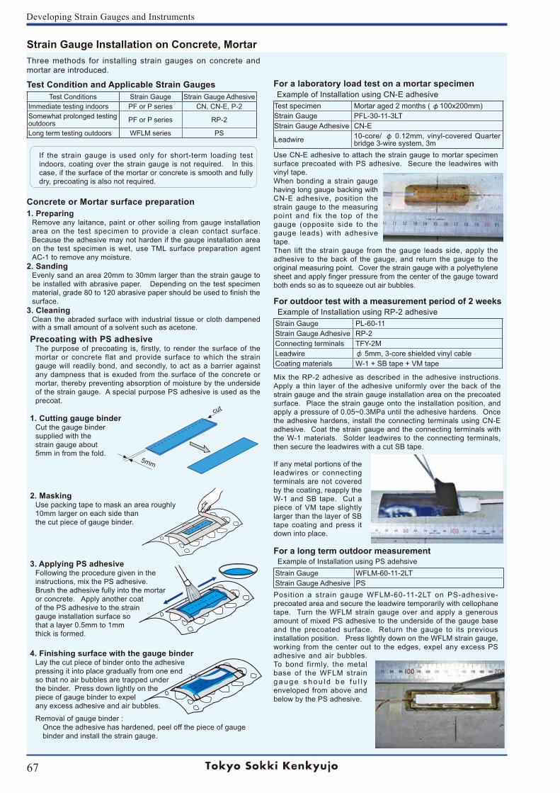
67
Developing Strain Gauges and Instruments
cut
5mm
Test Conditions Strain Gauge Strain Gauge AdhesiveImmediate testing indoors PF or P series CN, CN-E, P-2Somewhat prolonged testing outdoors PF or P series RP-2
Long term testing outdoors WFLM series PS
Example of Installation using PS adehsive
Example of Installation using RP-2 adhesive
Strain Gauge Installation on Concrete, Mortar
Concrete or Mortar surface preparation1. Preparing
Remove any laitance, paint or other soiling from gauge installation area on the test specimen to provide a clean contact surface. Because the adhesive may not harden if the gauge installation area on the test specimen is wet, use TML surface preparation agent AC-1 to remove any moisture.
2. SandingEvenly sand an area 20mm to 30mm larger than the strain gauge to be installed with abrasive paper. Depending on the test specimen material,grade80to120abrasivepapershouldbeusedtofinishthesurface.
3. CleaningClean the abraded surface with industrial tissue or cloth dampened with a small amount of a solvent such as acetone.
Test Condition and Applicable Strain Gauges
Precoating with PS adhesiveThe purpose of precoating is, firstly, to render the surface of the mortar or concrete flat and provide surface to which the strain gauge will readily bond, and secondly, to act as a barrier against any dampness that is exuded from the surface of the concrete or mortar, thereby preventing absorption of moisture by the underside of the strain gauge. A special purpose PS adhesive is used as the precoat.
1. Cutting gauge binderCut the gauge binder supplied with the strain gauge about 5mm in from the fold.
2. MaskingUse packing tape to mask an area roughly 10mm larger on each side than the cut piece of gauge binder.
3. Applying PS adhesiveFollowing the procedure given in theinstructions, mix the PS adhesive. Brush the adhesive fully into the mortaror concrete. Apply another coatof the PS adhesive to the straingauge installation surface so that a layer 0.5mm to 1mm thick is formed.
4. Finishing surface with the gauge binderLay the cut piece of binder onto the adhesive pressing it into place gradually from one endso that no air bubbles are trapped under the binder. Press down lightly on the piece of gauge binder to expel any excess adhesive and air bubbles.
Removal of gauge binder : Once the adhesive has hardened, peel off the piece of gauge binder and install the strain gauge.
For a laboratory load test on a mortar specimen
Test specimen Mortar aged 2 months ( φ100x200mm)Strain Gauge PFL-30-11-3LTStrain Gauge Adhesive CN-E
Leadwire 10-core/ φ 0.12mm, vinyl-covered Quarter bridge 3-wire system, 3m
Use CN-E adhesive to attach the strain gauge to mortar specimen surface precoated with PS adhesive. Secure the leadwires with vinyl tape.When bonding a strain gauge having long gauge backing with CN-E adhesive, position the strain gauge to the measuring point and fix the top of the gauge (opposite side to the gauge leads) with adhesive tape. Then lift the strain gauge from the gauge leads side, apply the adhesive to the back of the gauge, and return the gauge to the original measuring point. Cover the strain gauge with a polyethylene sheetandapplyfingerpressurefromthecenterofthegaugetowardboth ends so as to squeeze out air bubbles.
For outdoor test with a measurement period of 2 weeks
Strain Gauge PL-60-11Strain Gauge Adhesive RP-2Connecting terminals TFY-2MLeadwire φ 5mm, 3-core shielded vinyl cableCoating materials W-1 + SB tape + VM tape
Mix the RP-2 adhesive as described in the adhesive instructions. Apply a thin layer of the adhesive uniformly over the back of the strain gauge and the strain gauge installation area on the precoated surface. Place the strain gauge onto the installation position, and applyapressureof0.05~0.3MPauntiltheadhesivehardens.Oncethe adhesive hardens, install the connecting terminals using CN-E adhesive. Coat the strain gauge and the connecting terminals with the W-1 materials. Solder leadwires to the connecting terminals, then secure the leadwires with a cut SB tape.
If any metal portions of the leadwires or connecting terminals are not covered by the coating, reapply the W-1 and SB tape. Cut a piece of VM tape slightly larger than the layer of SB tape coating and press it down into place.
For a long term outdoor measurement
Strain Gauge WFLM-60-11-2LTStrain Gauge Adhesive PSPosition a strain gaugeWFLM-60-11-2LT on PS-adhesive-precoated area and secure the leadwire temporarily with cellophane tape. Turn the WFLM strain gauge over and apply a generous amount of mixed PS adhesive to the underside of the gauge base and the precoated surface. Return the gauge to its previous installation position. Press lightly down on the WFLM strain gauge, working from the center out to the edges, expel any excess PS adhesive and air bubbles. To bond firmly, the metal base of the WFLM strain g a u g e s h o u l d b e f u l l y enveloped from above and below by the PS adhesive.
Example of Installation using CN-E adhesive
Three methods for installing strain gauges on concrete and mortar are introduced.
If the strain gauge is used only for short-term loading test indoors, coating over the strain gauge is not required. In this case, if the surface of the mortar or concrete is smooth and fully dry, precoating is also not required.
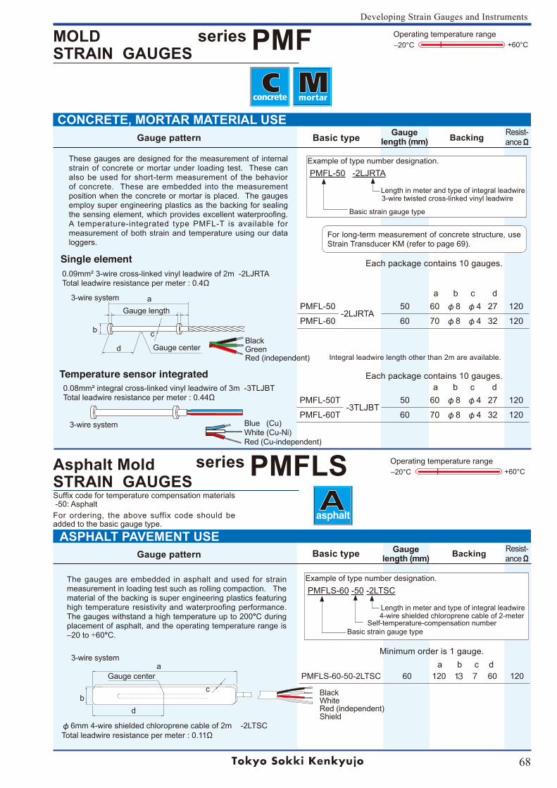
68
Developing Strain Gauges and Instruments
Gauge pattern Basic type Gauge length (mm) Backing Resist-
ance Ω
ASPHALT PAVEMENT USE
CONCRETE, MORTAR MATERIAL USE
Asphalt Mold STRAIN GAUGES
series PMFLS +60°C‒20°COperating temperature range
PMFL-50-2LJRTA
50 60 φ8 φ4 27 120
PMFL-60 60 70 φ8 φ4 32 120
PMFL-50T-3TLJBT
50 60 φ8 φ4 27 120
PMFL-60T 60 70 φ8 φ4 32 120
PMFLS-60-50-2LTSC 60 120 13 7 60 120
Gauge pattern Basic type Gauge length (mm) Backing
MOLD STRAIN GAUGES
series PMF +60°C‒20°COperating temperature range
Resist-ance Ω
Suffixcodefortemperaturecompensationmaterials -50: Asphalt For ordering, the above suffix code should be added to the basic gauge type.
Gauge center
a b c d
a b c d
a b c d
Integral leadwire length other than 2m are available.
Each package contains 10 gauges.
Gauge length
c
Gauge center
The gauges are embedded in asphalt and used for strain measurement in loading test such as rolling compaction. The material of the backing is super engineering plastics featuring high temperature resistivity and waterproofing performance. The gauges withstand a high temperature up to 200°C during placement of asphalt, and the operating temperature range is ‒20to+60°C.
3-wire system
For long-term measurement of concrete structure, use StrainTransducerKM(refertopage69).
a
b c
d
3-wire system
3-wire system
Minimum order is 1 gauge.
Each package contains 10 gauges.
a
bd
BlackWhite Red (independent) Shield
These gauges are designed for the measurement of internal strain of concrete or mortar under loading test. These can also be used for short-term measurement of the behavior of concrete. These are embedded into the measurement position when the concrete or mortar is placed. The gauges employ super engineering plastics as the backing for sealing thesensingelement,whichprovidesexcellentwaterproofing. A temperature-integrated type PMFL-T is available for measurement of both strain and temperature using our data loggers.
BlackGreenRed (independent)
Blue (Cu)White (Cu-Ni)Red (Cu-independent)
Single element 0.09mm²3-wirecross-linkedvinylleadwireof2m-2LJRTATotalleadwireresistancepermeter:0.4Ω
Temperature sensor integrated0.08mm² integral cross-linked vinyl leadwire of 3m -3TLJBTTotalleadwireresistancepermeter:0.44Ω
Example of type number designation. PMFL-50 -2LJRTA Length in meter and type of integral leadwire 3-wire twisted cross-linked vinyl leadwire Basic strain gauge type
φ6mm4-wireshieldedchloroprenecableof2m-2LTSCTotalleadwireresistancepermeter:0.11Ω
Example of type number designation. PMFLS-60 -50 -2LTSC Length in meter and type of integral leadwire 4-wire shielded chloroprene cable of 2-meter Self-temperature-compensation number Basic strain gauge type
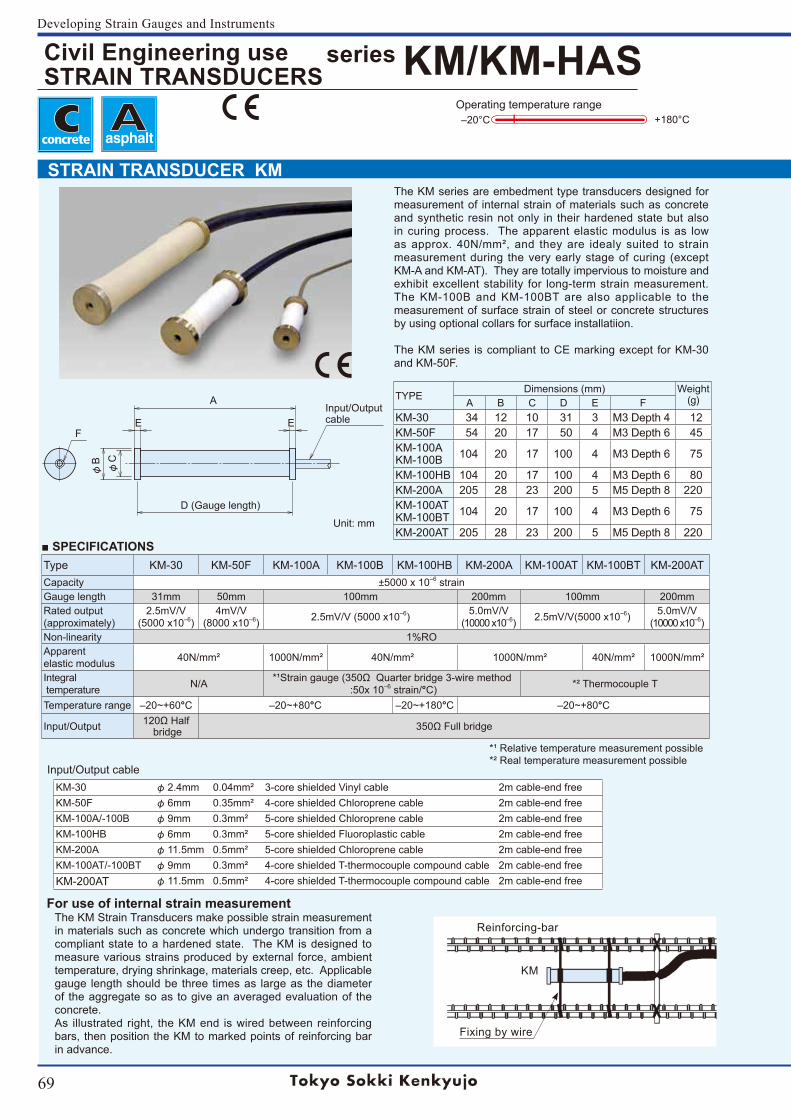
69
Developing Strain Gauges and Instruments
Civil Engineering useSTRAIN TRANSDUCERS
series KM/KM-HAS+180°C
Operating temperature range‒20°C
Input/Output cable
SPECIFICATIONS
STRAIN TRANSDUCER KM
Type KM-30 KM-50F KM-100A KM-100B KM-100HB KM-200A KM-100AT KM-100BT KM-200ATCapacity ±5000 x 10‒6 strainGauge length 31mm 50mm 100mm 200mm 100mm 200mmRated output(approximately)
2.5mV/V(5000 x10‒6)
4mV/V(8000 x10‒6) 2.5mV/V (5000 x10‒6) 5.0mV/V
(10000 x10‒6) 2.5mV/V(5000 x10‒6) 5.0mV/V(10000 x10‒6)
Non-linearity 1%ROApparentelastic modulus 40N/mm² 1000N/mm² 40N/mm² 1000N/mm² 40N/mm² 1000N/mm²
Integral temperature N/A *¹Straingauge(350ΩQuarterbridge3-wiremethod
:50x 10‒6 strain/°C) *² Thermocouple T
Temperature range ‒20~+60°C ‒20~+80°C ‒20~+180°C ‒20~+80°C
Input/Output 120ΩHalf bridge 350ΩFullbridge
TYPEDimensions (mm) Weight
(g)A B C D E FKM-30 34 12 10 31 3 M3 Depth 4 12KM-50F 54 20 17 50 4 M3Depth6 45KM-100AKM-100B 104 20 17 100 4 M3Depth6 75
KM-100HB 104 20 17 100 4 M3Depth6 80KM-200A 205 28 23 200 5 M5 Depth 8 220KM-100ATKM-100BT 104 20 17 100 4 M3Depth6 75
KM-200AT 205 28 23 200 5 M5 Depth 8 220
KM-30 φ2.4mm 0.04mm² 3-core shielded Vinyl cable 2m cable-end freeKM-50F φ6mm 0.35mm² 4-core shielded Chloroprene cable 2m cable-end freeKM-100A/-100B φ9mm 0.3mm² 5-core shielded Chloroprene cable 2m cable-end freeKM-100HB φ6mm 0.3mm² 5-core shielded Fluoroplastic cable 2m cable-end freeKM-200A φ11.5mm 0.5mm² 5-core shielded Chloroprene cable 2m cable-end freeKM-100AT/-100BT φ9mm 0.3mm² 4-core shielded T-thermocouple compound cable 2m cable-end freeKM-200AT φ11.5mm 0.5mm² 4-core shielded T-thermocouple compound cable 2m cable-end free
Reinforcing-bar
KM
Fixing by wire
*¹ Relative temperature measurement possible*² Real temperature measurement possible
The KM Strain Transducers make possible strain measurement in materials such as concrete which undergo transition from a compliant state to a hardened state. The KM is designed to measure various strains produced by external force, ambient temperature, drying shrinkage, materials creep, etc. Applicable gauge length should be three times as large as the diameter of the aggregate so as to give an averaged evaluation of the concrete.As illustrated right, the KM end is wired between reinforcing bars, then position the KM to marked points of reinforcing bar in advance.
For use of internal strain measurement
Unit: mm
Input/Output cable
D (Gauge length)
A
EEF
φB
φC
The KM series are embedment type transducers designed for measurement of internal strain of materials such as concrete and synthetic resin not only in their hardened state but also in curing process. The apparent elastic modulus is as low as approx. 40N/mm², and they are idealy suited to strain measurement during the very early stage of curing (except KM-A and KM-AT). They are totally impervious to moisture and exhibit excellent stability for long-term strain measurement. The KM-100B and KM-100BT are also applicable to the measurement of surface strain of steel or concrete structures by using optional collars for surface installatiion.
The KM series is compliant to CE marking except for KM-30 and KM-50F.
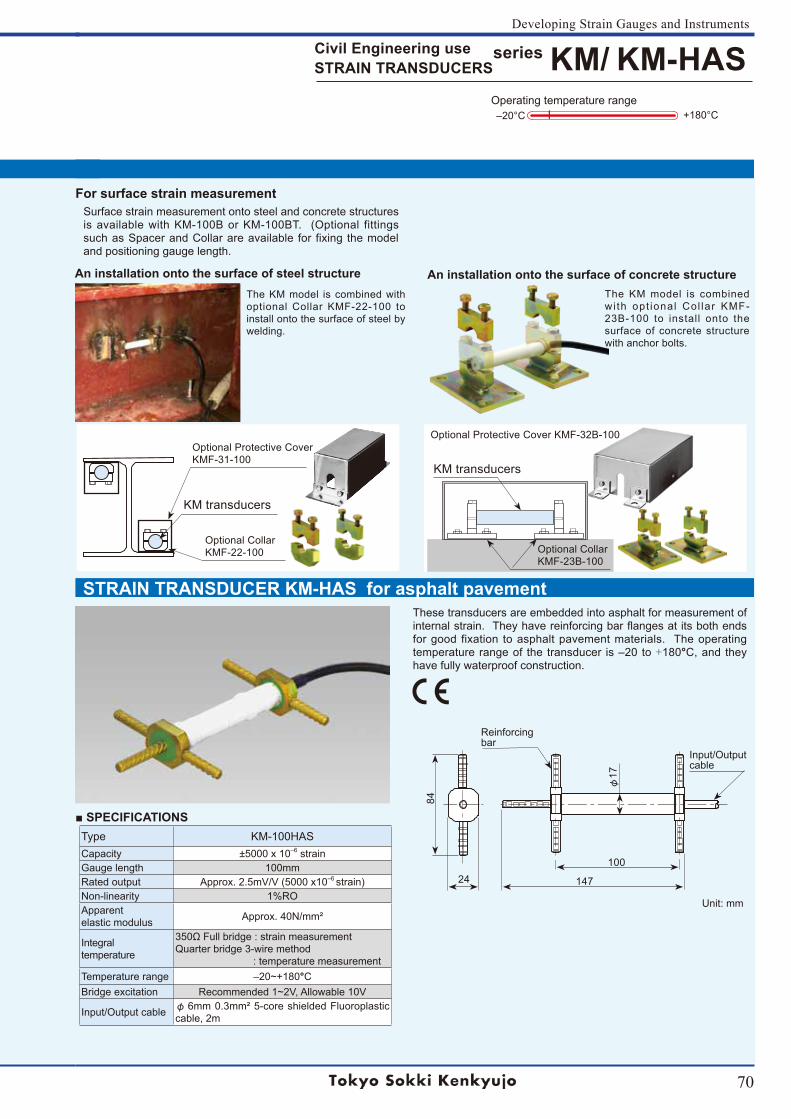
70
Developing Strain Gauges and Instruments
Civil Engineering useSTRAIN TRANSDUCERS
series KM/ KM-HAS+180°C
Operating temperature range‒20°C
SPECIFICATIONS
STRAIN TRANSDUCER KM-HAS for asphalt pavement
Type KM-100HASCapacity ±5000 x 10‒6 strainGauge length 100mmRated output Approx. 2.5mV/V (5000 x10‒6strain)Non-linearity 1%ROApparentelastic modulus Approx. 40N/mm²
Integral temperature
350ΩFullbridge:strainmeasurementQuarter bridge 3-wire method : temperature measurement
Temperature range ‒20~+180°CBridge excitation Recommended1~2V,Allowable10V
Input/Output cable φ 6mm0.3mm²5-coreshieldedFluoroplasticcable, 2m
Optional Protective CoverKMF-31-100
KM transducers
Optional CollarKMF-22-100
Optional Protective Cover KMF-32B-100
KM transducers
Optional CollarKMF-23B-100
These transducers are embedded into asphalt for measurement of internalstrain.Theyhavereinforcingbarflangesatitsbothendsfor good fixation to asphalt pavement materials. The operating temperaturerangeof the transducer is‒20to+180°C, and they have fully waterproof construction.
Surface strain measurement onto steel and concrete structures is available with KM-100B or KM-100BT. (Optional fittings such as Spacer and Collar are available for fixing the model and positioning gauge length.
An installation onto the surface of steel structure An installation onto the surface of concrete structureThe KM model is combined wi th opt ional Col lar KMF-23B-100 to install onto the surface of concrete structure with anchor bolts.
The KM model is combined with optional Collar KMF-22-100 to install onto the surface of steel by welding.
For surface strain measurement
Input/Output cable
Reinforcingbar
Unit: mm
100
14724
84
φ17
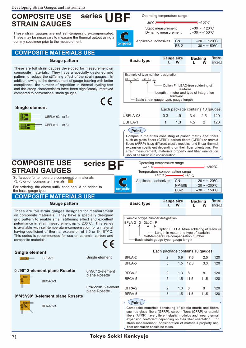
71
Developing Strain Gauges and Instruments
Gauge pattern Basic type Gauge size L W
Backing L W
Resist-ance Ω
COMPOSITE MATERIALS USE
COMPOSITE MATERIALS USE
Example of type number designation
UBFLA-1 -3LJB -F
Option F : LEAD-free soldering of leadwire Length in meter and type of integration leadwire Basic strain gauge type, gauge length
Example of type number designation
BFLA-2 -3 -3LJC -F
Option F : LEAD-free soldering of leadwire Length in meter and type of leadwire Self-temperature-compensation number Basic strain gauge type, gauge length
COMPOSITE USE STRAIN GAUGES
series BFApplicable adhesives CN ‒20~ +120ºC
NP-50B ‒20~ +200ºCEB-2 ‒30~ +150ºC
Suffixcodefortemperaturecompensationmaterials -3, -5 or -8 : composite materials Forordering, theabovesuffixcodeshouldbeaddedtothe basic gauge type.
These strain gauges are not self-temperature-compensated. These may be necessary to measure the thermal output using a dummy specimen prior to the measurement.
Operating temperature range+200°C‒20°C
Temperature compensation range+80°C+10°C
UBFLA-03 0.3 1.9 3.4 2.5 120
UBFLA-1 1 1.3 4.5 2 120
COMPOSITE USE STRAIN GAUGES
series UBF Operating temperature range
+150°C‒30°C
Applicable adhesives CN ‒20~ +120ºCEB-2 ‒30~ +150ºC
Staticmeasurement :‒30~+120°CDynamicmeasurement :‒30~+150°C
Gauge pattern Basic type Gauge size L W
Backing L W
Resist-ance Ω
BFLA-2 2 0.9 7.6 2.5 120
BFLA-5 5 1.5 12.3 3.3 120
BFCA-2 2 1.3 8 8 120BFCA-5 5 1.5 11.5 11.5 120
BFRA-2 2 1.3 8 8 120BFRA-5 5 1.5 11.5 11.5 120
Single element
0°/90°2-elementplane Rosette
0°/45°/90° 3-elementplane Rosette
Composite materials consisting of plastic matrix and fibers such as glass fibers (GFRP), carbon fibers (CFRP) or aramid fibers(AFRP)havedifferentelasticmodulusandlinearthermalexpansioncoefficientdependingontheirfiberorientation. Forstrain measurement, consideration of materials property and fiberorientationshouldbetaken.
Point
BFCA-2-3
BFLA-2
BFRA-2-3
Single element
0°/90° 2-element plane Rosette
0°/45°/90° 3-element plane Rosette
Each package contains 10 gauges.
Each package contains 10 gauges.
These are foil strain gauges designed for measurement on composite materials. They have a specially designed grid pattern to enable small stiffening effect and excellent peformance in strain measurement up to 200°C. This series is available with self-temperature-compensation for a material having coefficient of thermal expansion of 3,5 or 8×10⁻⁶/°C. This series is recommended for use on ceramic, carbon and composite materials.
UBFLA-03 (x 3)
UBFLA-1 (x 3)
Composite materials consisting of plastic matrix and fibers such as glass fibers (GFRP), carbon fibers (CFRP) or aramid fibers(AFRP)havedifferentelasticmodulusandlinearthermalexpansioncoefficientdependingontheirfiberorientation. Forstrain measurement, materials property and fiber orientation should be taken into consideration.
Point
These are foil strain gauges developed for measurement on composite materials. They have a specially designed grid pattern to reduce the stiffening effect of the strain gauges. In addition, owing to the development of gauge backing with better compliance, the number of repetition in thermal cycling test andthecreepcharacteristicshavebeensignificantly improvedcompared to conventional strain gauges.
Single element
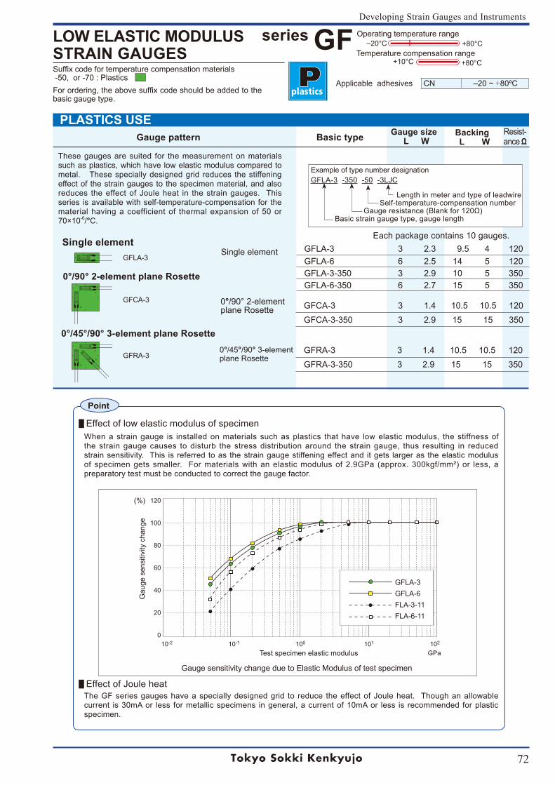
72
Developing Strain Gauges and Instruments
PLASTICS USE
Example of type number designation
GFLA-3 -350 -50 -3LJC
Length in meter and type of leadwire Self-temperature-compensation number Gaugeresistance(Blankfor120Ω) Basic strain gauge type, gauge length
Suffixcodefortemperaturecompensationmaterials -50, or -70 : PlasticsForordering,theabovesuffixcodeshouldbeaddedtothebasic gauge type.
LOW ELASTIC MODULUS STRAIN GAUGES
series GFApplicable adhesives CN ‒20~ +80ºC
Operating temperature range+80°C‒20°C
Temperature compensation range+80°C+10°C
Gauge pattern Basic type Gauge size L W
Backing L W
Resist-ance Ω
GFLA-3 3 2.3 9.5 4 120GFLA-6 6 2.5 14 5 120GFLA-3-350 3 2.9 10 5 350GFLA-6-350 6 2.7 15 5 350
GFCA-3 3 1.4 10.5 10.5 120GFCA-3-350 3 2.9 15 15 350
GFRA-3 3 1.4 10.5 10.5 120GFRA-3-350 3 2.9 15 15 350
These gauges are suited for the measurement on materials such as plastics, which have low elastic modulus compared to metal. These specially designed grid reduces the stiffening effect of the strain gauges to the specimen material, and also reduces the effect of Joule heat in the strain gauges. This series is available with self-temperature-compensation for the material having a coefficient of thermal expansion of 50 or 70×10-6/°C.
Each package contains 10 gauges.
Effect of low elastic modulus of specimenWhen a strain gauge is installed on materials such as plastics that have low elastic modulus, the stiffness of the strain gauge causes to disturb the stress distribution around the strain gauge, thus resulting in reduced strain sensitivity. This is referred to as the strain gauge stiffening effect and it gets larger as the elastic modulus ofspecimengetssmaller. Formaterialswithanelasticmodulusof2.9GPa (approx.300kgf/mm²)or less,apreparatory test must be conducted to correct the gauge factor.
Effect of Joule heat The GF series gauges have a specially designed grid to reduce the effect of Joule heat. Though an allowable current is 30mA or less for metallic specimens in general, a current of 10mA or less is recommended for plastic specimen.
120
100
80
60
40
20
0
(%)
10-2 10-1 100 101 102
GPaTest specimen elastic modulus
Gau
ge s
ensi
tivity
cha
nge
Gauge sensitivity change due to Elastic Modulus of test specimen
GFLA-3GFLA-6FLA-3-11FLA-6-11
Point
0°/90° 2-element plane Rosette
0°/45°/90° 3-element plane Rosette
Single elementGFLA-3
GFCA-3
GFRA-3
Single element
0°/90°2-elementplane Rosette
0°/45°/90° 3-element plane Rosette
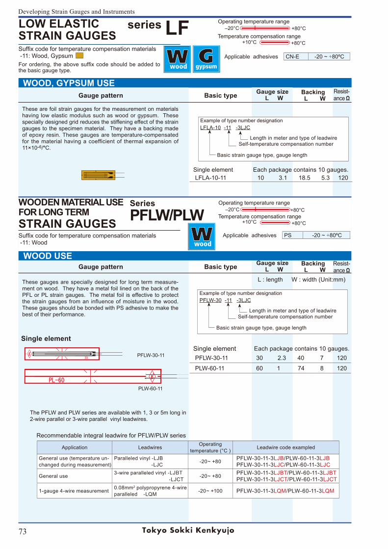
73
Developing Strain Gauges and Instruments
30
Example of type number designation
LFLA-10 -11 -3LJC
Length in meter and type of leadwire Self-temperature compensation number
Basic strain gauge type, gauge length
Example of type number designation
PFLW-30 -11 -3LJC
Length in meter and type of leadwire Self-temperature compensation number
Basic strain gauge type, gauge length
Recommendable integral leadwire for PFLW/PLW series
Application Leadwires Operatingtemperature (°C ) Leadwire code exampled
General use (temperature un-changed during measurement)
Paralleled vinyl -LJB -LJC -20~+80 PFLW-30-11-3LJB/PLW-60-11-3LJB
PFLW-30-11-3LJC/PLW-60-11-3LJC
General use 3-wire paralleled vinyl -LJBT -LJCT -20~+80 PFLW-30-11-3LJBT/PLW-60-11-3LJBT
PFLW-30-11-3LJCT/PLW-60-11-3LJCT
1-gauge 4-wire measurement 0.08mm2 polypropyrene 4-wire paralleled -LQM -20~+100 PFLW-30-11-3LQM/PLW-60-11-3LQM
Gauge pattern Basic type Gauge size L W
Backing L W
Resist-ance Ω
+80°C+10°C
L : length W : width (Unit:mm)
series LFLOW ELASTIC STRAIN GAUGES
Applicable adhesives CN-E -20 ~ +80ºC
Operating temperature range+80°C‒20°C
Temperature compensation range+80°C+10°C
Suffixcodefortemperaturecompensationmaterials -11: Wood, GypsumForordering, theabovesuffixcodeshouldbeaddedtothe basic gauge type.
WOOD, GYPSUM USE
WOODEN MATERIAL USE FOR LONG TERMSTRAIN GAUGES
SeriesPFLW/PLW
Operating temperature range+80°C‒20°C
Temperature compensation range
Applicable adhesives PS -20 ~ +80ºC
Backing L W
WOOD USE Gauge pattern Basic type Gauge size
L WResist-ance Ω
These are foil strain gauges for the measurement on materials having low elastic modulus such as wood or gypsum. These specially designed grid reduces the stiffening effect of the strain gauges to the specimen material. They have a backing made of epoxy resin. These gauges are temperature-compensated for the material having a coefficient of thermal expansion of 11×10-6/°C.
The PFLW and PLW series are available with 1, 3 or 5m long in 2-wire parallel or 3-wire parallel vinyl leadwires.
PLW-60-11
PFLW-30-11
These gauges are specially designed for long term measure-ment on wood. They have a metal foil lined on the back of the PFL or PL strain gauges. The metal foil is effective to protect the strain gauges from an influence of moisture in the wood. These gauges should be bonded with PS adhesive to make the best of their performance.
Suffixcodefortemperaturecompensationmaterials -11: Wood
Single element Each package contains 10 gauges.LFLA-10-11 10 3.1 18.5 5.3 120
Single element Each package contains 10 gauges.PFLW-30-11 30 2.3 40 7 120
PLW-60-11 60 1 74 8 120
Single element
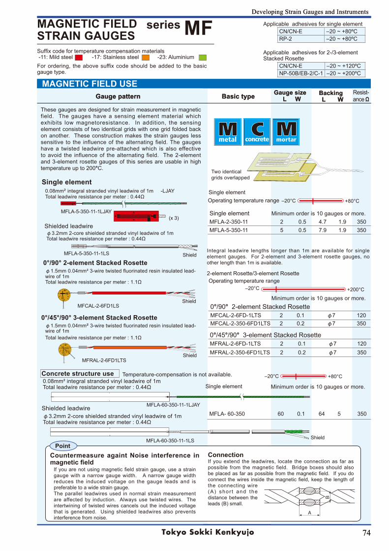
74
Developing Strain Gauges and Instruments
74
‒20°C
+200°C
B
A
Point
‒20°C +80°C
Suffixcodefortemperaturecompensationmaterials -11: Mild steel -17: Stainless steel -23: AluminiumFor ordering, the above suffix code should be added to the basic gauge type.
Gauge pattern Basic type Gauge size L W
Backing L W
Resist-ance Ω
series MFMAGNETIC FIELD STRAIN GAUGES
Applicable adhesives for 2-/3-elementStacked Rosette
CN/CN-E ‒20~+120ºCNP-50B/EB-2/C-1 ‒20~+200ºC
Developing Strain Gauges and Instruments
Gauge pattern Basic type Gauge size L W
Backing L W
MFLA-5-350-11-1LJAY
MFCAL-2-6FD1LS
MFRAL-2-6FD1LTS
Operating temperature range
Connection
+80°C
These gauges are designed for strain measurement in magnetic field. The gauges have a sensing element material which exhibits low magnetoresistance. In addition, the sensing element consists of two identical grids with one grid folded back on another. These construction makes the strain gauges less sensitive to the influence of the alternating field. The gauges have a twisted leadwire pre-attached which is also effective to avoid the influence of the alternating field. The 2-element and 3-element rosette gauges of this series are usable in high temperature up to 200°C. Two identical
grids overlapped
φ1.5mm 0.04mm² 3-wire twisted fluorinated resin insulated lead-wire of 1mTotalleadwireresistancepermeter:1.1Ω
φ1.5mm 0.04mm² 3-wire twisted fluorinated resin insulated lead-wire of 1mTotalleadwireresistancepermeter:1.1Ω
0.08mm² integral stranded vinyl leadwire of 1mTotalleadwireresistancepermeter:0.44Ω
φ3.2mm 2-core shielded stranded vinyl leadwire of 1mTotalleadwireresistancepermeter:0.44Ω
MAGNETIC FIELD USE
Single element
Ifyouarenotusingmagneticfieldstraingauge,useastraingauge with a narrow gauge width. A narrow gauge width reduces the induced voltage on the gauge leads and is preferable to a wide strain gauge. The parallel leadwires used in normal strain measurement are affected by induction. Always use twisted wires. The intertwining of twisted wires cancels out the induced voltage that is generated. Using shielded leadwires also prevents interference from noise.
If you extend the leadwires, locate the connection as far as possible from the magnetic field. Bridge boxes should also beplacedasfaraspossiblefromthemagneticfield. Ifyoudoconnect thewires insidethemagneticfield,keepthe lengthofthe connecting wire (A ) shor t and the distance between the leads (B) small.
Countermeasure againt Noise interference in magnetic field
Single elementMFLA-2-350-11 2 0.5 4.7 1.9 350MFLA-5-350-11 5 0.5 7.9 1.9 350
MFLA-60-350-11-1LJAY
(x 3)
Shield
Shield
Shield
MFLA-5-350-11-1LS
MFLA-60-350-11-1LS
MFLA-60-350 60 0.1 64 5 350
0°/45°/90° 3-element Stacked RosetteMFRAL-2-6FD-1LTS 2 0.1 φ7 120MFRAL-2-350-6FD1LTS 2 0.2 φ7 350
0°/90° 2-element Stacked RosetteMFCAL-2-6FD-1LTS 2 0.1 φ7 120MFCAL-2-350-6FD1LTS 2 0.2 φ7 350
0.08mm² integral stranded vinyl leadwire of 1m -LJAYTotalleadwireresistancepermeter:0.44Ω
φ3.2mm 2-core shielded stranded vinyl leadwire of 1mTotalleadwireresistancepermeter:0.44Ω
Operating temperature range‒20°C
Single element
2-element Rosette/3-element Rosette
Applicable adhesives for single elementCN/CN-E ‒20~+80ºCRP-2 ‒20~+80ºC
Integral leadwire lengths longer than 1m are available for single element gauges. For 2-element and 3-element rosette gauges, no other length than 1m is available.
0°/45°/90° 3-element Stacked Rosette
0°/90° 2-element Stacked Rosette
Single element
Shielded leadwire
Concrete structure use
Shielded leadwire
Minimum order is 10 gauges or more.
Minimum order is 10 gauges or more.
Minimum order is 10 gauges or more.
Temperature-compensation is not available.
Shield
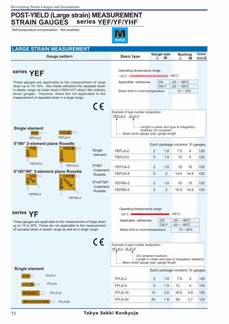
75
Developing Strain Gauges and Instruments
Each package contains 10 gauges.
Each package contains 10 gauges.
Gauge pattern Basic type Gauge size L W
Backing L W
Resist-ance Ω
POST-YIELD (Large strain) MEASUREMENTSTRAIN GAUGES series YEF/YF/YHF Self-temperature-compensation : Not available
Applicable adhesives CN ‒20 ~ +80ºCCN-Y ‒20 ~ +80ºC
Strain limit in room-temperature 10 ~ 15%
Applicable adhesives CN ‒20 ~ +80ºCCN-Y ‒20 ~ +80ºC
Strain limit in room-temperature 15 ~ 20%
Single element
YEFLA-2 2 1.8 7.5 4 120
YEFLA-5 5 1.9 12 4 120
0°/90° 2-element Rosette
YEFCA-2 2 1.8 10 10 120
YEFCA-5 5 2 14.5 14.5 120
0°/45°/90° 3-element Rosette
YEFRA-2 2 1.8 10 10 120
YEFRA-5 5 2 14.5 14.5 120
YFLA-2 2 1.8 7.5 4 120
YFLA-5 5 1.9 12 4 120
YFLA-10 10 2.6 16.6 4.9 120
YFLA-20 20 1.8 26 3.7 120
Example of type number designation YEFLA-2 -3LJC-F
Length in meter and type of integration leadwire CE compliant Basic strain gauge type, gauge length
Example of type number designation
YFLA-2 -3LJC-F
CE compliant leadwire Length in meter and type of integration leadwire Basic strain gauge type, gauge length
Single element
0°/90° 2-element plane Rosette
0°/45°/90° 3-element plane Rosette
Single element
YEFLA-2 YEFLA-5
YFLA-5
YFLA-2
YEFCA-2 YEFCA-5
YEFRA-2YEFRA-5
YFLA-10
YFLA-20
These gauges are applicable to the measurement of large strain up to 10~15%. Also these withstand the repeated strain in elastic range (at strain level ±1500×10-6 strain) like ordinary strain gauges. However, these are not applicable to the measurement of repeated strain in a large range.
These gauges are applicable to the measurement of large strain up to 15 to 20%. These are not applicable to the measurement of repeated strain in elastic range as well as in large range.
series YEF +80°C‒20°C
Operating temperature range
series YF +80°C‒20°C
Operating temperature range
LARGE STRAIN MEASUREMENT
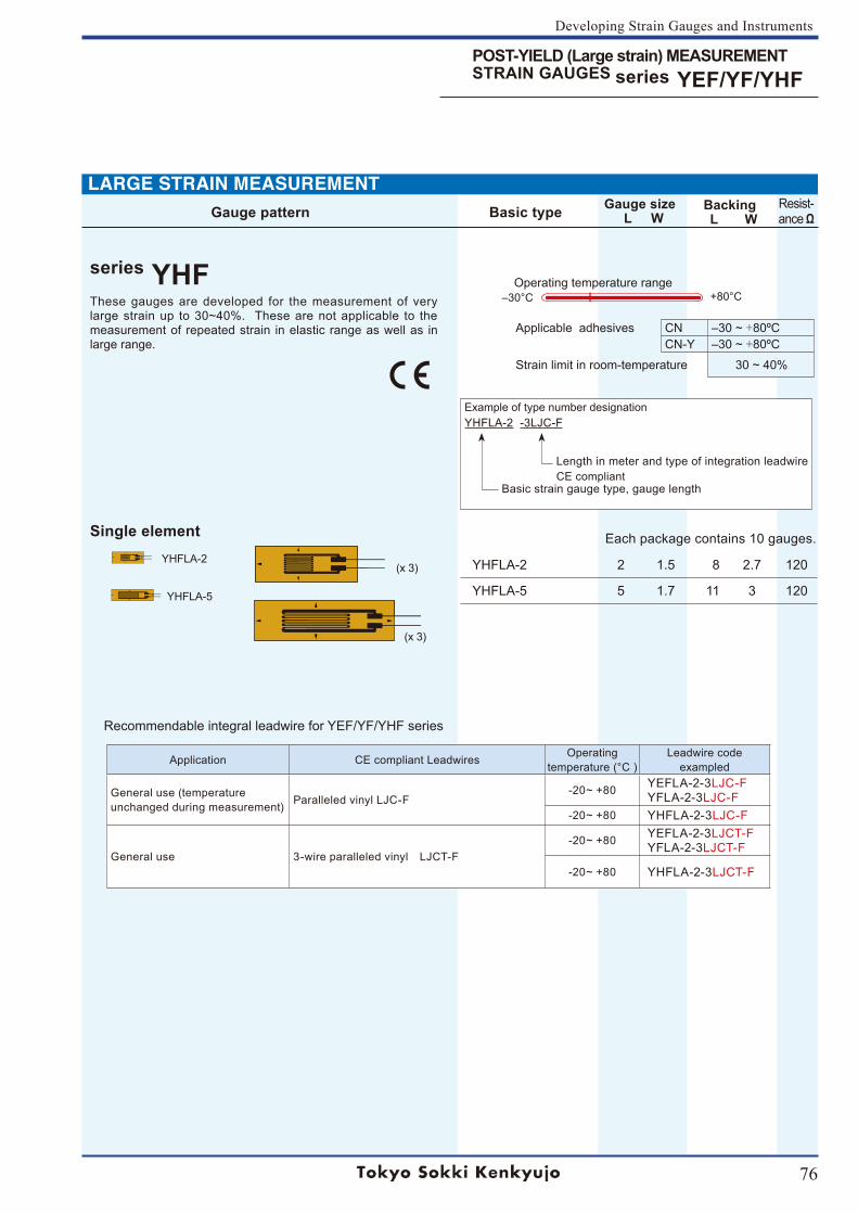
76
Developing Strain Gauges and Instruments
Gauge pattern Basic type Gauge size L W
Backing L W
Resist-ance Ω
series YHFApplicable adhesives CN ‒30 ~ +80ºC
CN-Y ‒30 ~ +80ºC
Strain limit in room-temperature 30 ~ 40%
YHFLA-2 2 1.5 8 2.7 120
YHFLA-5 5 1.7 11 3 120
POST-YIELD (Large strain) MEASUREMENTSTRAIN GAUGES series YEF/YF/YHF
Example of type number designation
YHFLA-2 -3LJC-F
Length in meter and type of integration leadwire CE compliant Basic strain gauge type, gauge length
Recommendable integral leadwire for YEF/YF/YHF series
Application CE compliant Leadwires Operatingtemperature (°C )
Leadwire code exampled
General use (temperature unchanged during measurement) Paralleled vinyl LJC-F
-20~ +80 YEFLA-2-3LJC-FYFLA-2-3LJC-F
-20~ +80 YHFLA-2-3LJC-F
General use 3-wire paralleled vinyl LJCT-F-20~ +80 YEFLA-2-3LJCT-F
YFLA-2-3LJCT-F
-20~ +80 YHFLA-2-3LJCT-F
+80°C‒30°COperating temperature range
Single element Each package contains 10 gauges.
These gauges are developed for the measurement of very large strain up to 30~40%. These are not applicable to the measurement of repeated strain in elastic range as well as in large range.
YHFLA-5
YHFLA-2
(x 3)
(x 3)
LARGE STRAIN MEASUREMENT
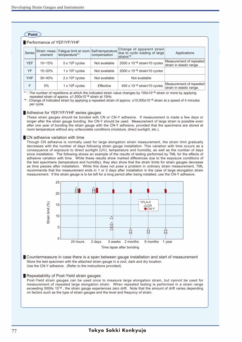
77
Developing Strain Gauges and Instruments
Performance of YEF/YF/YHF
Adhesive for YEF/YF/YHF series gaugesThese strain gauges should be bonded with CN or CN-Y adhesive. If measurement is made a few days or longer after the strain gauge bonding, the CN-Y should be used. Measurement of large strain is possible even after one year of bonding the strain gauge with the CN-Y adhesive, provided that the specimens are stored at room temperature without any unfavorable conditions (moisture, direct sunlight, etc.).
CN adhesive variation with timeThough CN adhesive is normally used for large elongation strain measurement, the strain limit gradually decreases with the number of days following strain gauge installation. This variation with time occurs as a consequence of exposure to direct sunlight (UV), temperature and humidity, as well as the number of days since installation. The following shows an example of the results of testing performed by TML for the effects of adhesive variation with time. While these results show marked differences due to the exposure conditions of the test specimens (temperature and humidity), they also show that the strain limits for strain gauges decrease as time passes after installation. While this does not pose a problem in ordinary strain measurement, TML recommends that the measurement ends in 1 or 2 days after installation in the case of large elongation strain measurement. If the strain gauge is to be left for a long period after being installed, use the CN-Y adhesive.
Countermeasure in case there is a span between gauge installation and start of measurementStore the test specimen with the attached strain gauge in a cool, dark and dry location.Use the CN-Y adhesive. (Refer to the instructions provided).
Repeatability of Post-Yield strain gaugesPost-Yield strain gauges can be used once to measure large elongation strain, but cannot be used for measurement of repeated large elongation strain. When repeated testing is performed in a strain range exceeding 5000x 10–6 , the strain gauge experiences zero drift. Note that the amount of drift varies depending on factors such as the type of strain gauges and the level and frequncy of strain.
Point
Series Strain meas-urement
Fatigue limit at room temperature*¹
Self-temperaturecompensation
Change of apparent strain due to cyclic loading of large strains*²
Applications
YEF 10~15% 5 x 10⁵ cycles Not available 2000 x 10–6 strain/10 cycles Measurement of repeated strain in elastic range.
YF 15~20% 1 x 10² cycles Not available 2000 x 10–6 strain/10 cycles
YHF 30~40% 2 x 10⁴ cycles Not available Not available
F 5% 1 x 10⁶ cycles Effective 400 x 10–6 strain/10 cycles Measurement of repeated strain in elastic range.
*¹ : The number of repetitions at which the indicated strain value changes by 100x10–6 strain or more by applying repeated strain of approx. ±1,500x10–6 strain at 15Hz*² : Change of indicated strain by applying a repeated strain of approx. ±10,000x10–6 strain at a speed of 4 minutes per cycle.
25
20
15
10
5
024 hours 2 days 3 weeks 2 months 6 months 1 year
Stra
in li
mit
(%)
Time lapse after bonding
YFLA-5CNCN-Y
YFLA-5CNCN-Y
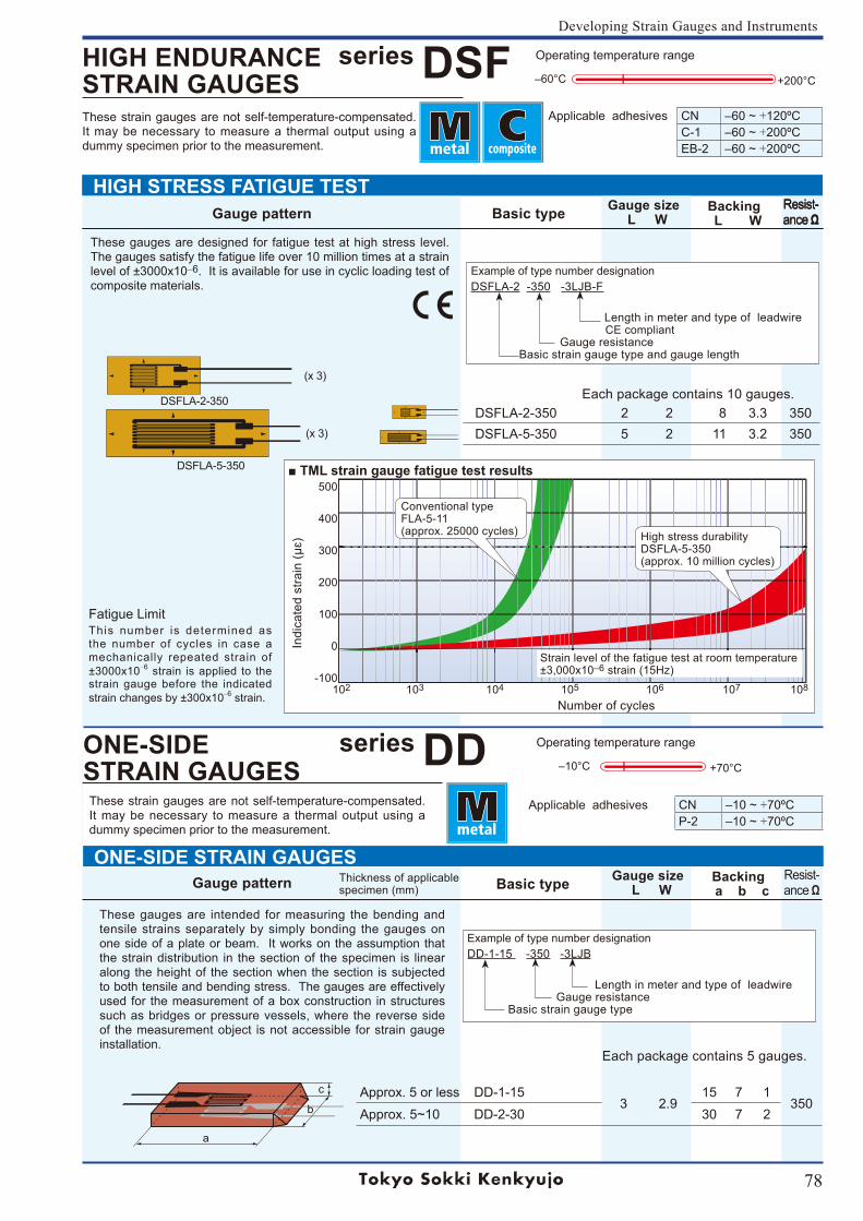
78
Developing Strain Gauges and Instruments
Gauge pattern Basic type Gauge size L W
Backing L W
Resist-ance Ω
DSFLA-2-350
(x 3)
(x 3)
DSFLA-5-350 TML strain gauge fatigue test results500
400
300
200
100
0
-100102 103 104 105 106 107 108
Number of cycles
Indi
cate
d st
rain
(μɛ)
Conventional type FLA-5-11(approx. 25000 cycles) High stress durability
DSFLA-5-350(approx. 10 million cycles)
Each package contains 10 gauges.
Strain level of the fatigue test at room temperature±3,000x10‒6 strain (15Hz)
DSFLA-2-350 2 2 8 3.3 350DSFLA-5-350 5 2 11 3.2 350
series DSFApplicable adhesives CN ‒60 ~ +120ºC
C-1 ‒60 ~ +200ºCEB-2 ‒60 ~ +200ºC
HIGH ENDURANCESTRAIN GAUGES
Resist-ance Ω
These strain gauges are not self-temperature-compensated. It may be necessary to measure a thermal output using a dummy specimen prior to the measurement.
+200°C‒60°C
Operating temperature range
HIGH STRESS FATIGUE TEST
These gauges are designed for fatigue test at high stress level. The gauges satisfy the fatigue life over 10 million times at a strain level of ±3000x10–6. It is available for use in cyclic loading test of composite materials.
Fatigue LimitThis number is determined as the number of cycles in case a mechanically repeated strain of ±3000x10–6 strain is applied to the strain gauge before the indicated strain changes by ±300x10–6 strain.
Thickness of applicablespecimen (mm)
Each package contains 5 gauges.
Approx. 5 or less DD-1-153 2.9
15 7 1350
Approx. 5~10 DD-2-30 30 7 2
These strain gauges are not self-temperature-compensated. It may be necessary to measure a thermal output using a dummy specimen prior to the measurement.
Applicable adhesives CN ‒10 ~ +70ºCP-2 ‒10 ~ +70ºC
ONE-SIDE STRAIN GAUGES Gauge pattern Basic type Gauge size
L WBacking
a b cResist-ance Ω
a
b
c
+70°C‒10°C
Operating temperature rangeseries DDONE-SIDESTRAIN GAUGES
These gauges are intended for measuring the bending and tensile strains separately by simply bonding the gauges on one side of a plate or beam. It works on the assumption that the strain distribution in the section of the specimen is linear along the height of the section when the section is subjected to both tensile and bending stress. The gauges are effectively used for the measurement of a box construction in structures such as bridges or pressure vessels, where the reverse side of the measurement object is not accessible for strain gauge installation.
Example of type number designation
DSFLA-2 -350 -3LJB-F
Length in meter and type of leadwire CE compliant Gauge resistance Basic strain gauge type and gauge length
Example of type number designation
DD-1-15 -350 -3LJB
Length in meter and type of leadwire Gauge resistance Basic strain gauge type
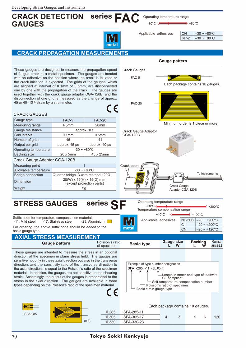
79
Developing Strain Gauges and Instruments
Each package contains 10 gauges.
(x 3)
Poisson's ratio of specimenGauge pattern Basic type Gauge size
L WBacking L W
Resist-ance Ω
Minimum order is 1 piece or more.
SFA-285
Each package contains 10 gauges.
‒20°C
+100°C+10°C
+200°COperating temperature range
Temperature compensation rangeseries SFSTRESS GAUGES
0.285 SFA-285-114 3 9 6 1200.305 SFA-305-17
0.330 SFA-330-23
Applicable adhesives NP-50B ‒20 ~ +200ºCC-1 ‒20 ~ +200ºCCN ‒20 ~ +120ºC
CRACK DETECTIONGAUGES
series FACApplicable adhesives CN ‒30 ~ +80ºC
RP-2 ‒30 ~ +80ºC
CRACK GAUGESGauge type FAC-5 FAC-20Measuring range 4.5mm 20mmGauge resistance approx. 1ΩGrid interval 0.1mm 0.5mmNumber of grids 46 41Output per grid approx. 45 με approx. 40 μεOperating temperature -30 ~ +80°CBacking size 28 x 5mm 43 x 25mmCrack Gauge Adaptor CGA-120BMeasuring point 1Allowable temperature -30 ~ +80°CBridge connection Quarter bridge 3-wire method 120Ω
Dimension 20(W) x 15(H) x 15(D) mm (except projection parts)
Weight 5g
Gauge pattern
CRACK PROPAGATION MEASUREMENTS
+80°C‒30°C
Operating temperature range
Suffix code for temperature compensation materials -11: Mild steel -17: Stainless steel -23: AluminiumFor ordering, the above suffix code should be added to the basic gauge type.
FAC-5
FAC-20
To instruments
Crack GaugeAdaptor CGA-120B
Crack Gauges
Crack Gauge AdaptorCGA-120B
These gauges are designed to measure the propagation speed of fatigue crack in a metal specimen. The gauges are bonded with an adhesive on the position where the crack is initiated or the crack initiation is expected. The grids of the gauges, which are aligned at interval of 0.1mm or 0.5mm, are disconnected one by one with the propagation of the crack. The gauges are used together with the crack gauge adaptor CGA-120B, and the disconnection of one grid is measured as the change of approx. 45 or 40×10-6 strain by a strainmeter.
These gauges are intended to measure the stress in an optional direction of the specimen in plane stress field. The gauges are sensitive not only in these axial direction but also in the transverse direction, and the sensitivity ratio of the transverse direction to the axial directions is equal to the Poisson’s ratio of the specimen material. In addition, the gauges are not sensitive to the shearing strain. Accordingly, the output of the gauges is proportional to the stress in the axial direction. The gauges are available in three types depending on the Poisson’s ratio of the specimen material.
AXIAL STRESS MEASUREMENT
Crack open
FAC
gau
ge
Example of type number designation
SFA -285 -11 -3LJC-F
Length in meter and type of leadwire CE compliant Self-temperature compensation number Poisson's ratio of specimen Basic strain gauge type
TML
TML
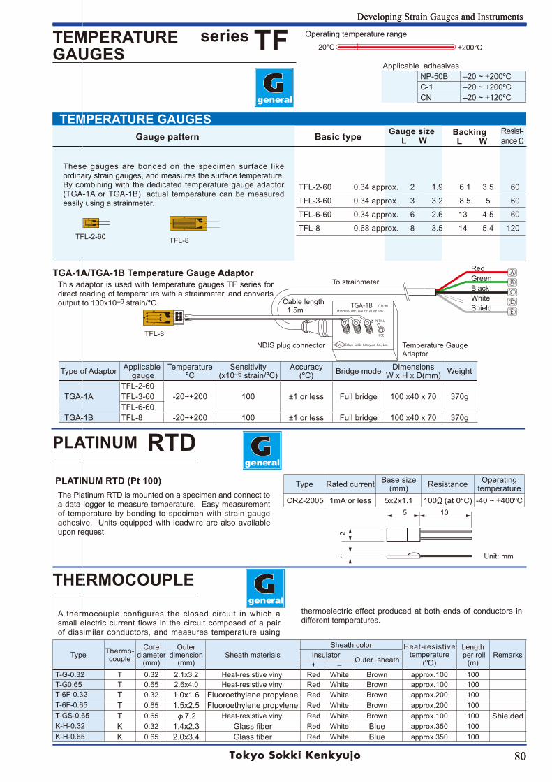
80
Developing Strain Gauges and Instruments
Gauge pattern Basic type Gauge size L W
Backing L W
Resist-ance Ω
80
Developing Strain Gauges and Instruments
+200°C‒20°C
Operating temperature range
TEMPERATURE GAUGES
TGA-1B (TFL-8 )TEMPERATURE GAUGE ADAPTOR
INITIAL
USE
TML Tokyo Sokki Kenkyujo Co., Ltd.
A B C D E
5 10
1
2
THERMOCOUPLE
1 2 3
Unit: mm
general
general
Applicable adhesives NP-50B ‒20 ~ +200ºCC-1 ‒20 ~ +200ºCCN ‒20 ~ +120ºC
Type Rated current Base size(mm) Resistance Operating
temperature CRZ-2005 1mA or less 5x2x1.1 100Ω (at 0°C) -40 ~ +400ºC
Type Thermo-couple
Corediameter
(mm)
Outer dimension
(mm)Sheath materials
Sheath color Heat-resistive temperature
(ºC)
Length per roll
(m)RemarksInsulator
Outer sheath+ ‒
T-G-0.32 T 0.32 2.1x3.2 Heat-resistive vinyl Red White Brown approx.100 100T-G0.65 T 0.65 2.6x4.0 Heat-resistive vinyl Red White Brown approx.100 100T-6F-0.32 T 0.32 1.0x1.6 Fluoroethylene propylene Red White Brown approx.200 100T-6F-0.65 T 0.65 1.5x2.5 Fluoroethylene propylene Red White Brown approx.200 100T-GS-0.65 T 0.65 φ7.2 Heat-resistive vinyl Red White Brown approx.100 100 ShieldedK-H-0.32 K 0.32 1.4x2.3 Glass fiber Red White Blue approx.350 100K-H-0.65 K 0.65 2.0x3.4 Glass fiber Red White Blue approx.350 100
Type of Adaptor Applicable gauge
Temperature°C
Sensitivity(x10‒6 strain/°C)
Accuracy(°C) Bridge mode Dimensions
W x H x D(mm) Weight
TGA-1ATFL-2-60
-20~+200 100 ±1 or less Full bridge 100 x40 x 70 370gTFL-3-60TFL-6-60
TGA-1B TFL-8 -20~+200 100 ±1 or less Full bridge 100 x40 x 70 370g
TFL-2-60 0.34 approx. 2 1.9 6.1 3.5 60
TFL-3-60 0.34 approx. 3 3.2 8.5 5 60
TFL-6-60 0.34 approx. 6 2.6 13 4.5 60
TFL-8 0.68 approx. 8 3.5 14 5.4 120
general
PLATINUM RTD (Pt 100)
RedGreenBlackWhiteShield
The Platinum RTD is mounted on a specimen and connect to a data logger to measure temperature. Easy measurement of temperature by bonding to specimen with strain gauge adhesive. Units equipped with leadwire are also available upon request.
A thermocouple configures the closed circuit in which a small electric current flows in the circuit composed of a pair of dissimilar conductors, and measures temperature using
thermoelectric effect produced at both ends of conductors in different temperatures.
These gauges are bonded on the specimen surface like ordinary strain gauges, and measures the surface temperature. By combining with the dedicated temperature gauge adaptor (TGA-1A or TGA-1B), actual temperature can be measured easily using a strainmeter.
TFL-2-60 TFL-8
series TFTEMPERATURE GAUGES
PLATINUM RTD
TGA-1A/TGA-1B Temperature Gauge AdaptorTo strainmeter
Cable length 1.5m
NDIS plug connector Temperature Gauge Adaptor
TFL-8
This adaptor is used with temperature gauges TF series for direct reading of temperature with a strainmeter, and converts output to 100x10‒6 strain/°C.
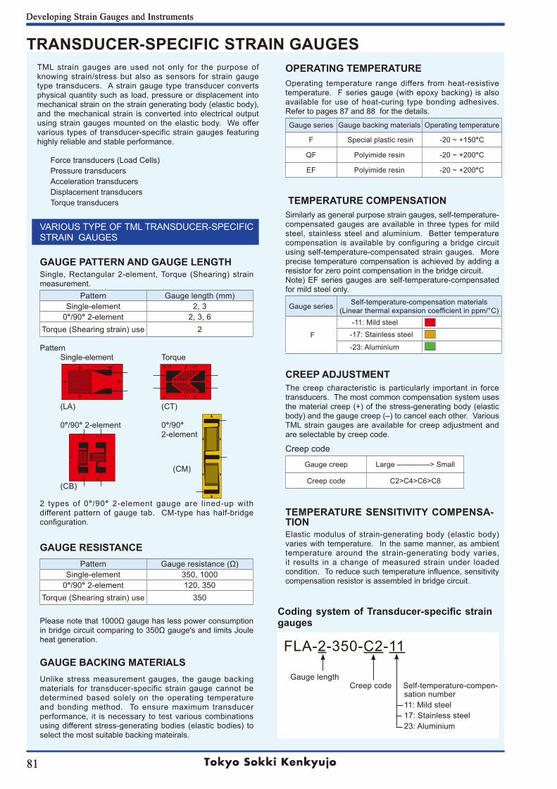
81
Developing Strain Gauges and Instruments
81
Developing Strain Gauges and Instruments
GAUGE BACKING MATERIALS Unlike stress measurement gauges, the gauge backing materials for transducer-specific strain gauge cannot be determined based solely on the operating temperature and bonding method. To ensure maximum transducer performance, it is necessary to test various combinations using different stress-generating bodies (elastic bodies) to select the most suitable backing mateirals.
OPERATING TEMPERATUREOperating temperature range differs from heat-resistive temperature. F series gauge (with epoxy backing) is also available for use of heat-curing type bonding adhesives. Refer to pages 87 and 88 for the details.
Gauge series Gauge backing materials Operating temperature
F Special plastic resin -20 ~ +150°C
QF Polyimide resin -20 ~ +200°C
EF Polyimide resin -20 ~ +200°C
CREEP ADJUSTMENTThe creep characteristic is particularly important in force transducers. The most common compensation system uses the material creep (+) of the stress-generating body (elastic body) and the gauge creep (‒) to cancel each other. Various TML strain gauges are available for creep adjustment and are selectable by creep code.
Creep code
Gauge creep Large ‒‒‒‒‒‒‒‒> Small
Creep code C2>C4>C6>C8
TEMPERATURE SENSITIVITY COMPENSA-TION Elastic modulus of strain-generating body (elastic body) varies with temperature. In the same manner, as ambient temperature around the strain-generating body varies, it results in a change of measured strain under loaded condition. To reduce such temperature influence, sensitivity compensation resistor is assembled in bridge circuit.
TRANSDUCER-SPECIFIC STRAIN GAUGESTML strain gauges are used not only for the purpose of knowing strain/stress but also as sensors for strain gauge type transducers. A strain gauge type transducer converts physical quantity such as load, pressure or displacement into mechanical strain on the strain generating body (elastic body), and the mechanical strain is converted into electrical output using strain gauges mounted on the elastic body. We offer various types of transducer-specific strain gauges featuring highly reliable and stable performance.
Force transducers (Load Cells)Pressure transducersAcceleration transducersDisplacement transducersTorque transducers
VARIOUS TYPE OF TML TRANSDUCER-SPECIFIC STRAIN GAUGES
GAUGE PATTERN AND GAUGE LENGTHSingle, Rectangular 2-element, Torque (Shearing) strain measurement.
Pattern Gauge length (mm)Single-element 2, 3
0°/90° 2-element 2, 3, 6Torque (Shearing strain) use 2
Pattern Single-element Torque
(LA) (CT)
0°/90° 2-element 0°/90° 2-element
(CM)
(CB)
2 types of 0°/90° 2-element gauge are lined-up with different pattern of gauge tab. CM-type has half-bridge configuration.
GAUGE RESISTANCEPattern Gauge resistance (Ω)
Single-element 350, 10000°/90° 2-element 120, 350
Torque (Shearing strain) use 350
Please note that 1000Ω gauge has less power consumption in bridge circuit comparing to 350Ω gauge's and limits Joule heat generation.
Coding system of Transducer-specific strain gauges
FLA-2-350-C2-11 Gauge length Creep code Self-temperature-compen- sation number 11: Mild steel 17: Stainless steel 23: Aluminium
TEMPERATURE COMPENSATIONSimilarly as general purpose strain gauges, self-temperature-compensated gauges are available in three types for mild steel, stainless steel and aluminium. Better temperature compensation is available by configuring a bridge circuit using self-temperature-compensated strain gauges. More precise temperature compensation is achieved by adding a resistor for zero point compensation in the bridge circuit. Note) EF series gauges are self-temperature-compensated for mild steel only.
Gauge series Self-temperature-compensation materials(Linear thermal expansion coefficient in ppm/°C)
F
-11: Mild steel-17: Stainless steel
-23: Aluminium
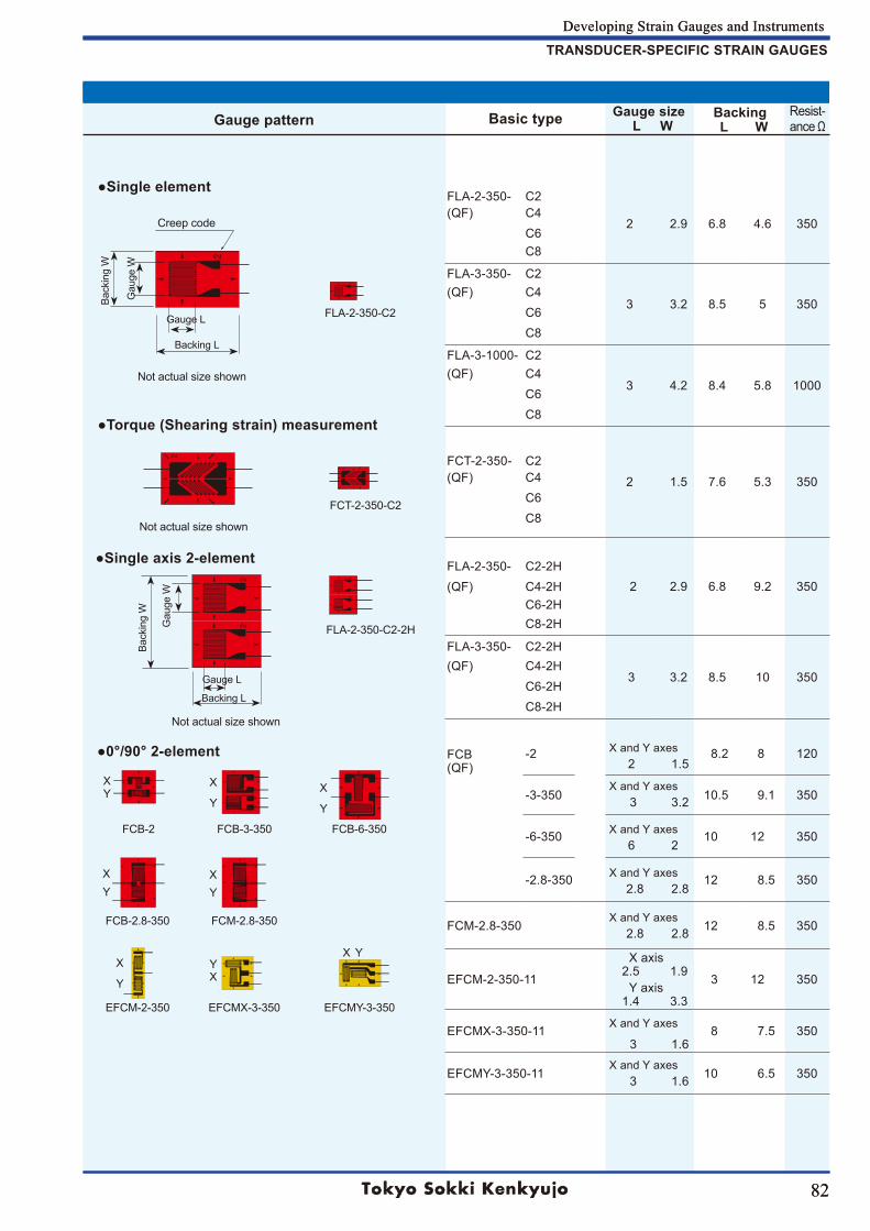
82
Developing Strain Gauges and Instruments
Gauge pattern Basic type Gauge size L W
Backing L W
Resist-ance Ω
82
Developing Strain Gauges and Instruments
FLA-2-350- C2
2 2.9 6.8 4.6 350(QF) C4
C6C8
FLA-3-350- C2
3 3.2 8.5 5 350(QF) C4
C6C8
FLA-3-1000- C2
3 4.2 8.4 5.8 1000(QF) C4
C6C8
FCT-2-350- C2
2 1.5 7.6 5.3 350(QF) C4C6C8
2 2.9 6.8 9.2 350FLA-2-350- C2-2H(QF) C4-2H
C6-2HC8-2H
FLA-3-350- C2-2H
3 3.2 8.5 10 350(QF) C4-2H
C6-2HC8-2H
FCB(QF)
-2 X and Y axes 8.2 8 120 2 1.5
-3-350X and Y axes
10.5 9.1 350 3 3.2
-6-350 X and Y axes 10 12 350 6 2
-2.8-350 X and Y axes 12 8.5 350 2.8 2.8
FCM-2.8-350X and Y axes
12 8.5 350 2.8 2.8
EFCM-2-350-11
X axis 2.5 1.9
3 12 350Y axis
1.4 3.3
EFCMX-3-350-11 X and Y axes 8 7.5 350 3 1.6
EFCMY-3-350-11X and Y axes
10 6.5 350 3 1.6
Single axis 2-element
Not actual size shown
Single element
Creep code
FLA-2-350-C2-2H
FCT-2-350-C2
FLA-2-350-C2
Not actual size shown
Torque (Shearing strain) measurement
0°/90° 2-element
TRANSDUCER-SPECIFIC STRAIN GAUGES
Backing L
Gauge L
Gau
ge W
Back
ing
W
Gau
ge W
Not actual size shown
Gauge L
Back
ing
W
Backing L
FCB-2 FCB-3-350 FCB-6-350
EFCMY-3-350EFCMX-3-350EFCM-2-350
FCM-2.8-350FCB-2.8-350
XY
X
YX
Y
XY
XY
X
Y XY
X Y
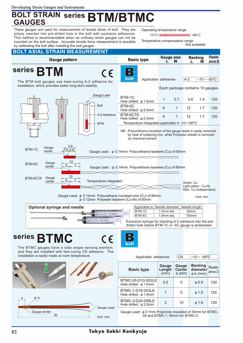
83
Developing Strain Gauges and Instruments
83
Developing Strain Gauges and Instruments
series BTM/BTMC
series BTM
series BTMC
Gauge Lead
Bolt
A-2 Adhesive
BTM
5.61.8 3.8
5 712
5 712
Gauge center
Gauge center
Gauge center
Gauge Lead : φ 0.14mm Polyurethanel leadwire (Cu) of 80mm
Gauge Lead : φ 0.14mm Polyurethane leadwire (Cu) of 80mm
Gauge Lead: φ 0.14mm Polyurethane insulated wire (Cu) of 80mm φ 0.12mm Polyester leadwire (Cu-Ni) of 80mm
BTM-1C
BTM-6C
BTM-6CTATemperature integrated
Optional syringe and needle Applicable to Needle diameter Needle lengthBTM-1C 1.5mm-dia. 60mmBTM-6C 1.8mm-dia. 100mm
Exclusive syringe for injecting A-2 adhesive into the pre-drilled hole before BTM-1C or -6C gauge is embedded.
NB : Polyurethane insulation of the gauge leads is easily removed by heat of soldering iron, while Polyester sheath is removed by chemical solvent.
Green: CuLight yellow : Cu-NiRed : Cu (independent)
Gauge center50
Gauge Lead
a φ b
Temperature compensation range Not available
Unit: mm
Unit: mm
Gauge pattern Basic type Gauge size L W
Backing L W
Resist-ance ΩGauge pattern Basic type Gauge size
L WBacking L W
Resist-ance Ω
+80°C‒10°COperating temperature range
BOLT STRAIN GAUGES
The BTM bolt gauges use heat-curing A-2 adhesive for installation, which provides better long-term stability.
BOLT AXIAL STRAIN MEASUREMENT
Each package contains 10 gauges.
BTM-1CHole drilled: φ1.6mm 1 0.7 5.6 1.4 120
BTM-6CHole drilled: φ2.0mm 6 1 12 1.7 120
BTM-6CTAHole drilled: φ2.0mm 6 1 12 1.7 120
Temperature integrated applicable in -10~+80°C
The BTMC gauges have a tube shape sensing element, and they are installed with fast-curing CN adhesive. The installation is easily made at room temperature.
Basic typeGaugeLength(mm)
GaugeCentera (mm)
Backing diameter φb (mm)
Resist-ance Ω
BTMC-05-D10-003LEHole drilled: φ1.0mm 0.5 5 φ0.9 120
BTMC-1-D16-003LEHole drilled: φ1.6mm 1 5 φ1.5 120
BTMC-3-D20-006LEHole drilled: φ2.0mm 3 10 φ1.9 120
Gauge Lead: φ0.1mm Polyimide insulated of 30mm for BTMC- 05 and BTMC-1, 60mm for BTMC-3
Applicable adhesives A-2 ‒10 ~ +80ºC
Applicable adhesives CN ‒10 ~ +80ºC
These gauges are used for measurement of tensile strain of bolt. They are simply inserted into pre-drilled hole in the bolt with exclusive adhesives. This method is recommendable when an ordinary strain gauges can not be mounted on the bolt surface. Accurate tensile force measurement is possible by calibrating the bolt after installing the bolt gauges.
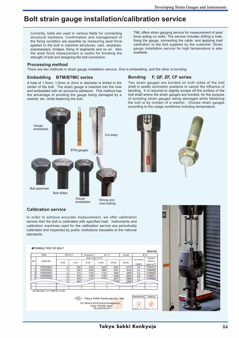
84
Developing Strain Gauges and Instruments
84
Developing Strain Gauges and Instruments
Bolt strain gauge installation/calibration service
Calibration service
BTM gauges
Cut away
Gauge embedded
Bolt specimen Bolt drilled
Gauge embedded Wiring and
overcoating
Currently, bolts are used in various fields for connecting structural members. Confirmation and management of the fixing condition are possible by measuring axial force applied to the bolt in machine structures, cars, airplanes, expressways, bridges, fixing of segments and so on. Also the axial force measurement is useful for knowing the strength of bolt and designing the bolt connection.
TML offers strain gauging service for measurement of axial force acting on bolts. The service includes drilling a hole, fixing the gauge, connecting the cable, and applying load calibration to the bolt supplied by the customer. Strain gauge installation service for high temperature is also available.
Processing methodThere are two methods in strain gauge installation service. One is embedding, and the other is bonding.
Embedding BTM/BTMC seriesA hole of 1.0mm, 1.6mm or 2mm in diameter is drilled in the center of the bolt. The strain gauge is inserted into the hole and embedded with an exclusive adhesive. This method has the advantage of avoiding the gauge being damaged by a washer, etc. while fastening the bolt.
Bonding F, QF, ZF, CF seriesTwo strain gauges are bonded on both sides of the bolt shaft in axially symmetric positions to cancel the influence of bending. It is required to slightly scrape off the surface of the bolt shaft where the strain gauges are bonded, for the purpose of avoiding strain gauges being damaged while fastening the bolt or by contact of a washer. Choose strain gauges according to the usage conditions including temperature.
In order to achieve accurate measurement, we offer calibration service that the bolt is calibrated with specified load. Instruments and calibration machines used for the calibration service are periodically calibrated and inspected by public institutions traceable to the national standards.
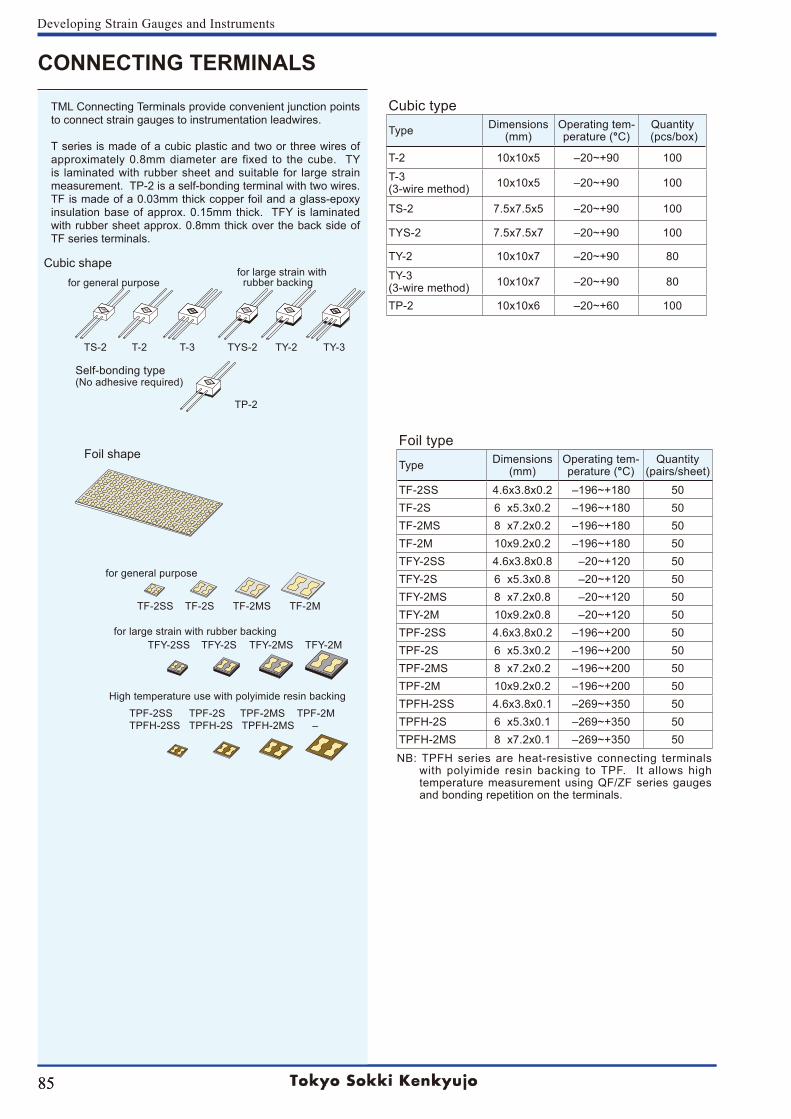
85
Developing Strain Gauges and Instruments
85
CONNECTING TERMINALS
Cubic type
Type Dimensions(mm)
Operating tem-perature (°C)
Quantity (pcs/box)
T-2 10x10x5 ‒20~+90 100
T-3 (3-wire method) 10x10x5 ‒20~+90 100
TS-2 7.5x7.5x5 ‒20~+90 100
TYS-2 7.5x7.5x7 ‒20~+90 100
TY-2 10x10x7 ‒20~+90 80
TY-3 (3-wire method) 10x10x7 ‒20~+90 80
TP-2 10x10x6 ‒20~+60 100
Foil type
Type Dimensions(mm)
Operating tem-perature (°C)
Quantity(pairs/sheet)
TF-2SS 4.6x3.8x0.2 ‒196~+180 50TF-2S 6 x5.3x0.2 ‒196~+180 50TF-2MS 8 x7.2x0.2 ‒196~+180 50TF-2M 10x9.2x0.2 ‒196~+180 50TFY-2SS 4.6x3.8x0.8 ‒20~+120 50TFY-2S 6 x5.3x0.8 ‒20~+120 50TFY-2MS 8 x7.2x0.8 ‒20~+120 50TFY-2M 10x9.2x0.8 ‒20~+120 50TPF-2SS 4.6x3.8x0.2 ‒196~+200 50TPF-2S 6 x5.3x0.2 ‒196~+200 50TPF-2MS 8 x7.2x0.2 ‒196~+200 50TPF-2M 10x9.2x0.2 ‒196~+200 50TPFH-2SS 4.6x3.8x0.1 ‒269~+350 50TPFH-2S 6 x5.3x0.1 ‒269~+350 50TPFH-2MS 8 x7.2x0.1 ‒269~+350 50NB: TPFH series are heat-resistive connecting terminals
with polyimide resin backing to TPF. It allows high temperature measurement using QF/ZF series gauges and bonding repetition on the terminals.
TML Connecting Terminals provide convenient junction points to connect strain gauges to instrumentation leadwires.
T series is made of a cubic plastic and two or three wires of approximately 0.8mm diameter are fixed to the cube. TY is laminated with rubber sheet and suitable for large strain measurement. TP-2 is a self-bonding terminal with two wires. TF is made of a 0.03mm thick copper foil and a glass-epoxy insulation base of approx. 0.15mm thick. TFY is laminated with rubber sheet approx. 0.8mm thick over the back side of TF series terminals.
Cubic shape
Foil shape
TS-2 T-2 T-3 TYS-2 TY-2 TY-3
TP-2
TF-2SS TF-2S TF-2MS TF-2M
TFY-2SS TFY-2S TFY-2MS TFY-2M
for general purpose
Self-bonding type(No adhesive required)
for general purpose
for large strain with rubber backing
for large strain with rubber backing
High temperature use with polyimide resin backingTPF-2SS TPF-2S TPF-2MS TPF-2MTPFH-2SS TPFH-2S TPFH-2MS ‒
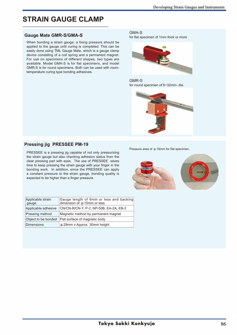
86
Developing Strain Gauges and Instruments
86
Developing Strain Gauges and Instruments
STRAIN GAUGE CLAMP
Applicable strain gauge
Gauge length of 6mm or less and backing dimension of φ15mm or less
Applicable adhesive CN/CN-R/CN-Y, P-2, NP-50B, EA-2A, EB-2Pressing method Magnetic method by permanent magnetObject to be bonded Flat surface of magnetic bodyDimensions φ29mm x Approx. 30mm height
PRESSEE is a pressing jig capable of not only pressurizing the strain gauge but also checking adhesion status from the clear pressing part with eyes. The use of PRESSEE saves time to keep pressing the strain gauge with your finger in the bonding work. In addition, since the PRESSEE can apply a constant pressure to the strain gauge, bonding quality is expected to be higher than a finger pressure.
Pressure area of φ19mm for flat specimen.
When bonding a strain gauge, a fixing pressure should be applied to the gauge until curing is completed. This can be easily done using TML Gauge Mate, which is a gauge clamp device consisting of a coil spring and a permanent magnet. For use on specimens of different shapes, two types are available. Model GMA-S is for flat specimens, and model GMR-S is for round specimens. Both can be used with room-temperature curing type bonding adhesives.
Gauge Mate GMR-S/GMA-S
Pressing jig PRESSEE PM-19
GMA-Sfor flat specimen of 1mm thick or more
GMR-Sfor round specimen of 6~32mm- dia.
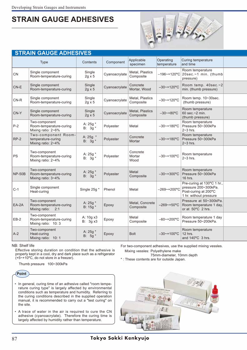
87
Developing Strain Gauges and Instruments
STRAIN GAUGE ADHESIVES
STRAIN GAUGE ADHESIVES
• In general, curing time of an adhesive called "room tempe-rature curing type" is largely affected by environmental conditions such as temperature and humidity. Referring to the curing conditions described in the supplied operation manual, it is recommended to carry out a "test curing" on the site.
• A trace of water in the air is required to cure the CN adhesive (cyanoacrylate). Therefore the curing time is largely affected by humidity rather than temperature.
Type Contents Component Applicable specimen
Operatingtemperature
Curing temperature and time Shelf life Applications
CN Single componentRoom-temperature-curing
Single2g x 5 Cyanoacrylate Metal, Plastics
Composite ‒196~+120°CRoom temperature20sec.~1 min. (thumb pressure)
6 monthsSingle component adhesive for strain gauges. The time required to bond the gauge is extremely short and handling is very easy. The thin bonding layer allows adhesion to plastic objects as well as metal. Curing time under normal conditions is 20~60 seconds.
CN-E Single componentRoom-temperature-curing
Single2g x 5 Cyanoacrylate Concrete
Mortar, Wood ‒30~+120°C Room temp. 40sec.~2 min. (thumb pressure) 6 months
Single component adhesive featuring high viscosity for bonding strain gauges to porous materials such as concrete and mortar. Curing time under normal conditions is 40~120 seconds.
CN-R Single componentRoom-temperature-curing
Single2g x 5 Cyanoacrylate Metal, Plastics
Composite ‒30~+120°C Room temp. 10~30sec. (thumb pressure) 3 months
Single component adhesive for accelerating cures in lower ambient temperature, or lower relative humidity. Curing time under normal conditions is 10~30 seconds.
CN-Y Single componentRoom-temperature-curing
Single2g x 5 Cyanoacrylate Metal, Plastics
Composite ‒30~+80°CRoom temperature 60 sec.~2 min. (thumb pressure)
6 monthsSingle component adhesive designed exclusively for use on post-yield strain gauge. Offers minimum degradation in bonding performance (peel strength) due to aging. Suitable when a large strain measurement is made after a few days or more of bonding the strain gauge. Curing time under normal conditions is 60~120 seconds.
P-2Two-component Room-temperature-curingMixing ratio: 2~6%
A: 25g * B: 3g * Polyester Metal ‒30~+180°C
Room temperaturePressure 50~300kPa 2~3 hrs.
6 monthsTwo-component room-temperature-curing polyester adhesive for bonding PF, P and F series strain gauges. Put the necessary quantity of drug A in the supplied mixing vessel, then add drug B by drops to total 2~6% in weight of drug A. Use the mixed adhesive within 5~15 minutes.
RP-2Two-componen t Room-temperature-curingMixing ratio: 2~4%
A: 25g * B: 3g * Polyester Concrete
Mortar ‒30~+180°CRoom temperaturePressure 50~300kPa 2~3 hrs.
3 monthsTwo-component room-temperature-curing polyester adhesive for bonding PF and P series strain gauges. The mixing procedure is the same as above for P-2 adhesive. Put the necessary quantity of drug A in the supplied mixing vessel, then add drug B by drops to total 2~4% by weight of drug A. Use the mixed adhesive within 10~20 minutes.
PSTwo-component Room-temperature-curingMixing ratio: 2~4%
A: 25g * B: 3g * Polyester
ConcreteMortarWood
‒30~+100°C Room temperature2~3 hrs. 3 months
Two-component room-temperature-curing polyester adhesive. Use as a surface precoating agent for bonding P and PF series gauges to concrete and also as an adhesive for WFLM series gauges. The special filler contained exhibits alkali resistance and effectively shuts off moisture and gas from inside of the concrete. Its high viscosity enables use on vertical walls or ceilings. Put the necessary quantity of drug A in the supplied mixing vessel, then add drug B by drops to total 2~4% by weight of drug A.
NP-50BTwo-component Room-temperature-curingMixing ratio: 3~4%
A: 25g * B: 3g * Polyester Metal
Composite ‒30~+300°CRoom temperaturePressure 50~300kPa16 hrs.
6 monthsTwo-component room-temperature-curing polyester adhesive for bonding QF, ZF and BF series strain gauges. Put the necessary quantity of drug A into the supplied mixing vessel then add drug B by drops to total 3~4% by weight of drug A. Use the mixed adhesive within 5~20 minutes.
C-1 Single componentHeat-curing Single 25g * Phenol Metal ‒269~+200°C
Pre-curing at 130°C 1 hr., pressure 200~300kPa.Post-curing at 200°C 1 hr. without pressure
3 months
Single-component heat-curing type adhesive. For use on strain gauges that are suited to heat curing. Enables reliable measurement for long periods and in high temperature up to 200°C.
EA-2ATwo-component Room-temperature-curingMixing ratio: 2:1
A: 25g * B: 15g * Epoxy Metal, Concrete
Composite ‒269~+50°CPressure at 50~300kPa.Room temperature 1 day, or at 50°C 2 hrs.
3 monthsTwo-component room-temperature-curing epoxy adhesive for bonding CF series strain gauges for use in temperature from cryogenic (‒269°C) up to 50°C. Mix the necessary quantity of drugs A and B at the weight ratio of 2 to 1.
EB-2Two-component Room-temperature-curingMixing ratio: 10: 3
A: 10g x3B: 3g x3 Epoxy Metal
Composite ‒60~+200°C Room temperature 1 dayPressure 50~200kPa. 3 months
Two-component room-temperature-curing epoxy adhesive for bonding strain gauges for use in temperature from ‒60 to +200°C. Enables stable measurement for a long period of time. Mix the necessary quantity of drugs A and B at the weight ratio of 10 to 3.
A-2Two-componentHeat-curingMixing ratio: 10: 1
A: 25g *B: 5g * Epoxy Bolt ‒30~+100°C
Room temperature12 hrs.and 140°C 3 hrs.
3 monthsTwo-component heat-curing epoxy adhesive for bonding BTM strain gauges. Mix the necessary quantity of drugs A and B at the weight ratio of 10 to 1, then pour the mixed adhesive into a hole drilled on the bolt in which the gauge is inserted. Keep at room temperature for 12 hours, then cure at 140°C in furnace for 3 hours.
Point
NB: Shelf lifeEffective storing duration on condition that the adhesive is properly kept in a cool, dry and dark place such as a refrigerator (+5~+10°C, do not store in a freezer).
Thumb pressure 100~300kPa
For two-component adhesives, use the supplied mixing vessles. Mixing vessles: Polyethylene make 75mm-diameter, 10mm depth* : These contents are for outside Japan.
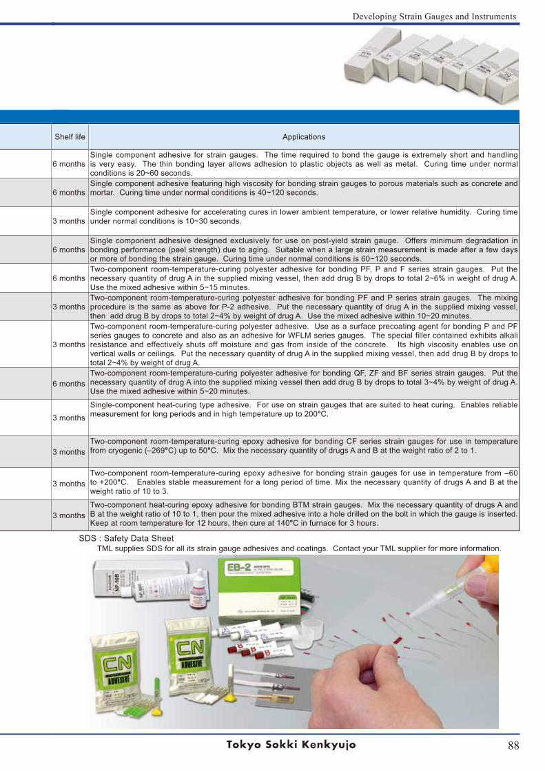
88
Developing Strain Gauges and Instruments
Type Contents Component Applicable specimen
Operatingtemperature
Curing temperature and time Shelf life Applications
CN Single componentRoom-temperature-curing
Single2g x 5 Cyanoacrylate Metal, Plastics
Composite ‒196~+120°CRoom temperature20sec.~1 min. (thumb pressure)
6 monthsSingle component adhesive for strain gauges. The time required to bond the gauge is extremely short and handling is very easy. The thin bonding layer allows adhesion to plastic objects as well as metal. Curing time under normal conditions is 20~60 seconds.
CN-E Single componentRoom-temperature-curing
Single2g x 5 Cyanoacrylate Concrete
Mortar, Wood ‒30~+120°C Room temp. 40sec.~2 min. (thumb pressure) 6 months
Single component adhesive featuring high viscosity for bonding strain gauges to porous materials such as concrete and mortar. Curing time under normal conditions is 40~120 seconds.
CN-R Single componentRoom-temperature-curing
Single2g x 5 Cyanoacrylate Metal, Plastics
Composite ‒30~+120°C Room temp. 10~30sec. (thumb pressure) 3 months
Single component adhesive for accelerating cures in lower ambient temperature, or lower relative humidity. Curing time under normal conditions is 10~30 seconds.
CN-Y Single componentRoom-temperature-curing
Single2g x 5 Cyanoacrylate Metal, Plastics
Composite ‒30~+80°CRoom temperature 60 sec.~2 min. (thumb pressure)
6 monthsSingle component adhesive designed exclusively for use on post-yield strain gauge. Offers minimum degradation in bonding performance (peel strength) due to aging. Suitable when a large strain measurement is made after a few days or more of bonding the strain gauge. Curing time under normal conditions is 60~120 seconds.
P-2Two-component Room-temperature-curingMixing ratio: 2~6%
A: 25g * B: 3g * Polyester Metal ‒30~+180°C
Room temperaturePressure 50~300kPa 2~3 hrs.
6 monthsTwo-component room-temperature-curing polyester adhesive for bonding PF, P and F series strain gauges. Put the necessary quantity of drug A in the supplied mixing vessel, then add drug B by drops to total 2~6% in weight of drug A. Use the mixed adhesive within 5~15 minutes.
RP-2Two-componen t Room-temperature-curingMixing ratio: 2~4%
A: 25g * B: 3g * Polyester Concrete
Mortar ‒30~+180°CRoom temperaturePressure 50~300kPa 2~3 hrs.
3 monthsTwo-component room-temperature-curing polyester adhesive for bonding PF and P series strain gauges. The mixing procedure is the same as above for P-2 adhesive. Put the necessary quantity of drug A in the supplied mixing vessel, then add drug B by drops to total 2~4% by weight of drug A. Use the mixed adhesive within 10~20 minutes.
PSTwo-component Room-temperature-curingMixing ratio: 2~4%
A: 25g * B: 3g * Polyester
ConcreteMortarWood
‒30~+100°C Room temperature2~3 hrs. 3 months
Two-component room-temperature-curing polyester adhesive. Use as a surface precoating agent for bonding P and PF series gauges to concrete and also as an adhesive for WFLM series gauges. The special filler contained exhibits alkali resistance and effectively shuts off moisture and gas from inside of the concrete. Its high viscosity enables use on vertical walls or ceilings. Put the necessary quantity of drug A in the supplied mixing vessel, then add drug B by drops to total 2~4% by weight of drug A.
NP-50BTwo-component Room-temperature-curingMixing ratio: 3~4%
A: 25g * B: 3g * Polyester Metal
Composite ‒30~+300°CRoom temperaturePressure 50~300kPa16 hrs.
6 monthsTwo-component room-temperature-curing polyester adhesive for bonding QF, ZF and BF series strain gauges. Put the necessary quantity of drug A into the supplied mixing vessel then add drug B by drops to total 3~4% by weight of drug A. Use the mixed adhesive within 5~20 minutes.
C-1 Single componentHeat-curing Single 25g * Phenol Metal ‒269~+200°C
Pre-curing at 130°C 1 hr., pressure 200~300kPa.Post-curing at 200°C 1 hr. without pressure
3 months
Single-component heat-curing type adhesive. For use on strain gauges that are suited to heat curing. Enables reliable measurement for long periods and in high temperature up to 200°C.
EA-2ATwo-component Room-temperature-curingMixing ratio: 2:1
A: 25g * B: 15g * Epoxy Metal, Concrete
Composite ‒269~+50°CPressure at 50~300kPa.Room temperature 1 day, or at 50°C 2 hrs.
3 monthsTwo-component room-temperature-curing epoxy adhesive for bonding CF series strain gauges for use in temperature from cryogenic (‒269°C) up to 50°C. Mix the necessary quantity of drugs A and B at the weight ratio of 2 to 1.
EB-2Two-component Room-temperature-curingMixing ratio: 10: 3
A: 10g x3B: 3g x3 Epoxy Metal
Composite ‒60~+200°C Room temperature 1 dayPressure 50~200kPa. 3 months
Two-component room-temperature-curing epoxy adhesive for bonding strain gauges for use in temperature from ‒60 to +200°C. Enables stable measurement for a long period of time. Mix the necessary quantity of drugs A and B at the weight ratio of 10 to 3.
A-2Two-componentHeat-curingMixing ratio: 10: 1
A: 25g *B: 5g * Epoxy Bolt ‒30~+100°C
Room temperature12 hrs.and 140°C 3 hrs.
3 monthsTwo-component heat-curing epoxy adhesive for bonding BTM strain gauges. Mix the necessary quantity of drugs A and B at the weight ratio of 10 to 1, then pour the mixed adhesive into a hole drilled on the bolt in which the gauge is inserted. Keep at room temperature for 12 hours, then cure at 140°C in furnace for 3 hours.
SDS : Safety Data SheetTML supplies SDS for all its strain gauge adhesives and coatings. Contact your TML supplier for more information.
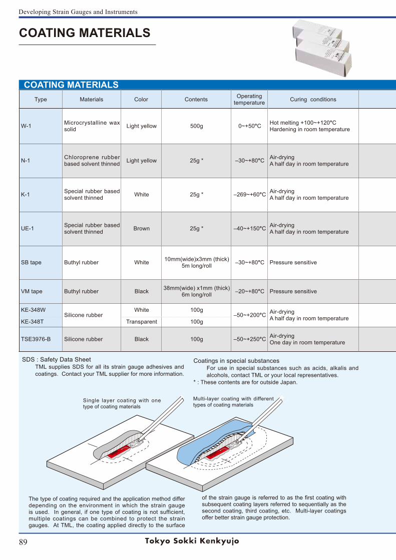
89
Developing Strain Gauges and Instruments
COATING MATERIALS
COATING MATERIALS Type Materials Color Contents Operating
temperature Curing conditions Purpose Applications
W-1 Microcrystalline wax solid Light yellow 500g 0~+50°C Hot melting +100~+120°C
Hardening in room temperature
Moisture- and water-proofing coating for laboratory and field requirements where mechanical protection is not needed, or used as the first coating for multi-layer coating.
The solid W-1 is put into a heating appratus (temperature-regulated oil bath is recommended) and completely melted at 100 to 120°C. The hot melted W-1 is applied over the area to be coated with a brush. The W-1 cools down and turns into solid as soon as applied. It is usually applied repeatedly till the cooled W-1 forms an adequate thickness.
N-1 Chloroprene rubber based solvent thinned Light yellow 25g * ‒30~+80°C Air-drying
A half day in room temperature
Moisture- and water-proofing coating for laboratory and less severe field requirements where mechanical protection is not needed.
A layer of N-1 is applied directly from the tube or with a brush over the area to be coated. Curing time is about half a day in room temperature, but it depends on conditions such as the specimen material, temperature, and so on. If the coating layer is too thin, apply on more layer to make an adequate thickness.
K-1 Special rubber based solvent thinned White 25g * ‒269~+60°C Air-drying
A half day in room temperature
Moisture-proofing coating from cryogenic to room temperature for laboratory requirements. Does not provide a high degree of mechanical protection.
A layer of K-1 is applied directly from the tube or with a brush over the area to be coated. Curing time is about half a day in room temperature, but it depends on conditions such as the specimen material, temperature, and so on. If the coating layer is too thin, apply on more layer to make an adequate thickness.
UE-1 Special rubber based solvent thinned Brown 25g * ‒40~+150°C Air-drying
A half day in room temperature
Oi l - res is tant coat ing for laboratory and f ie ld requirements. Does not provide a high degree of mechanical protection.
A layer of UE-1 is applied directly from the tube or with a brush over the area to be coated. Curing time is about half a day in room temperature, but it depends on conditions such as the specimen material, temperature, and so on. If the coating layer is too thin, apply another layer to make an adequate thickness.
SB tape Buthyl rubber White 10mm(wide)x3mm (thick)5m long/roll ‒30~+80°C Pressure sensitive
Moisture- and water-proofing coating for laboratory and field requirements where mechanical protection is not needed, or used as the first coating for multi-layer coating. Offers excellent moisture and water resistant characteristics and is very convenient for use.
The SB tape is cut in an appropriate length and applied over the area to be coated. The application is completed by pressing down the SB tape firmly with a spatula or your finger covered with the separating paper. It is also applied under the leadwire prior to the overcoating.
VM tape Buthyl rubber Black 38mm(wide) x1mm (thick)6m long/roll ‒20~+80°C Pressure sensitive
Used as the second coating or later for multi-layer coating. Offers excellent moisture and water resistant characteristics. Very convenient for use.
The VM tape is cut in an appropriate length and applied over the area to be coated with finger pressure. The VM tape must not be applied directly over a strain gauge as a first coating.
KE-348WSilicone rubber
White 100g‒50~+200°C Air-drying
A half day in room temperature
Suitable for laboratory requirements with high temperature condit ions where high degree of mechanical protection is not needed.
The KE-348 is applied directly from the tube over the area to be coated. Curing time is about one day in room temperature, but it depends on conditions such as temperature, humidity and so on. KE-348T Transparent 100g
TSE3976-B Silicone rubber Black 100g ‒50~+250°C Air-dryingOne day in room temperature
Suitable for laboratory requirements with high temperature condit ions where high degree of mechanical protection is not needed.
The TSE3976-B is applied directly from the tube over the area to be coated. Curing time is about one day in room temperature, but it depends on conditions such as temperature, humidity and so on.
The type of coating required and the application method differ depending on the environment in which the strain gauge is used. In general, if one type of coating is not sufficient, multiple coatings can be combined to protect the strain gauges. At TML, the coating applied directly to the surface
of the strain gauge is referred to as the first coating with subsequent coating layers referred to sequentially as the second coating, third coating, etc. Multi-layer coatings offer better strain gauge protection.
SDS : Safety Data SheetTML supplies SDS for all its strain gauge adhesives and coatings. Contact your TML supplier for more information.
Coatings in special substancesFor use in special substances such as acids, alkalis and alcohols, contact TML or your local representatives.
* : These contents are for outside Japan.
Single layer coating with one type of coating materials
Multi-layer coating with different types of coating materials
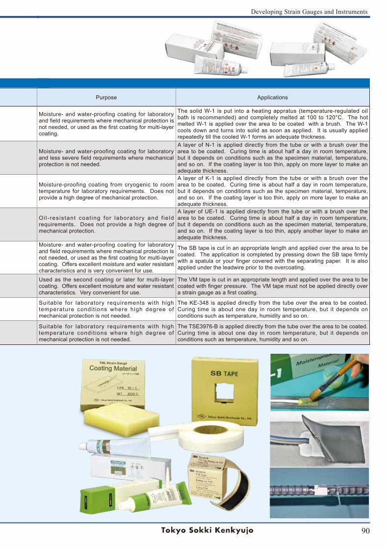
90
Developing Strain Gauges and Instruments
Type Materials Color Contents Operatingtemperature Curing conditions Purpose Applications
W-1 Microcrystalline wax solid Light yellow 500g 0~+50°C Hot melting +100~+120°C
Hardening in room temperature
Moisture- and water-proofing coating for laboratory and field requirements where mechanical protection is not needed, or used as the first coating for multi-layer coating.
The solid W-1 is put into a heating appratus (temperature-regulated oil bath is recommended) and completely melted at 100 to 120°C. The hot melted W-1 is applied over the area to be coated with a brush. The W-1 cools down and turns into solid as soon as applied. It is usually applied repeatedly till the cooled W-1 forms an adequate thickness.
N-1 Chloroprene rubber based solvent thinned Light yellow 25g * ‒30~+80°C Air-drying
A half day in room temperature
Moisture- and water-proofing coating for laboratory and less severe field requirements where mechanical protection is not needed.
A layer of N-1 is applied directly from the tube or with a brush over the area to be coated. Curing time is about half a day in room temperature, but it depends on conditions such as the specimen material, temperature, and so on. If the coating layer is too thin, apply on more layer to make an adequate thickness.
K-1 Special rubber based solvent thinned White 25g * ‒269~+60°C Air-drying
A half day in room temperature
Moisture-proofing coating from cryogenic to room temperature for laboratory requirements. Does not provide a high degree of mechanical protection.
A layer of K-1 is applied directly from the tube or with a brush over the area to be coated. Curing time is about half a day in room temperature, but it depends on conditions such as the specimen material, temperature, and so on. If the coating layer is too thin, apply on more layer to make an adequate thickness.
UE-1 Special rubber based solvent thinned Brown 25g * ‒40~+150°C Air-drying
A half day in room temperature
Oi l - res is tant coat ing for laboratory and f ie ld requirements. Does not provide a high degree of mechanical protection.
A layer of UE-1 is applied directly from the tube or with a brush over the area to be coated. Curing time is about half a day in room temperature, but it depends on conditions such as the specimen material, temperature, and so on. If the coating layer is too thin, apply another layer to make an adequate thickness.
SB tape Buthyl rubber White 10mm(wide)x3mm (thick)5m long/roll ‒30~+80°C Pressure sensitive
Moisture- and water-proofing coating for laboratory and field requirements where mechanical protection is not needed, or used as the first coating for multi-layer coating. Offers excellent moisture and water resistant characteristics and is very convenient for use.
The SB tape is cut in an appropriate length and applied over the area to be coated. The application is completed by pressing down the SB tape firmly with a spatula or your finger covered with the separating paper. It is also applied under the leadwire prior to the overcoating.
VM tape Buthyl rubber Black 38mm(wide) x1mm (thick)6m long/roll ‒20~+80°C Pressure sensitive
Used as the second coating or later for multi-layer coating. Offers excellent moisture and water resistant characteristics. Very convenient for use.
The VM tape is cut in an appropriate length and applied over the area to be coated with finger pressure. The VM tape must not be applied directly over a strain gauge as a first coating.
KE-348WSilicone rubber
White 100g‒50~+200°C Air-drying
A half day in room temperature
Suitable for laboratory requirements with high temperature condit ions where high degree of mechanical protection is not needed.
The KE-348 is applied directly from the tube over the area to be coated. Curing time is about one day in room temperature, but it depends on conditions such as temperature, humidity and so on. KE-348T Transparent 100g
TSE3976-B Silicone rubber Black 100g ‒50~+250°C Air-dryingOne day in room temperature
Suitable for laboratory requirements with high temperature condit ions where high degree of mechanical protection is not needed.
The TSE3976-B is applied directly from the tube over the area to be coated. Curing time is about one day in room temperature, but it depends on conditions such as temperature, humidity and so on.
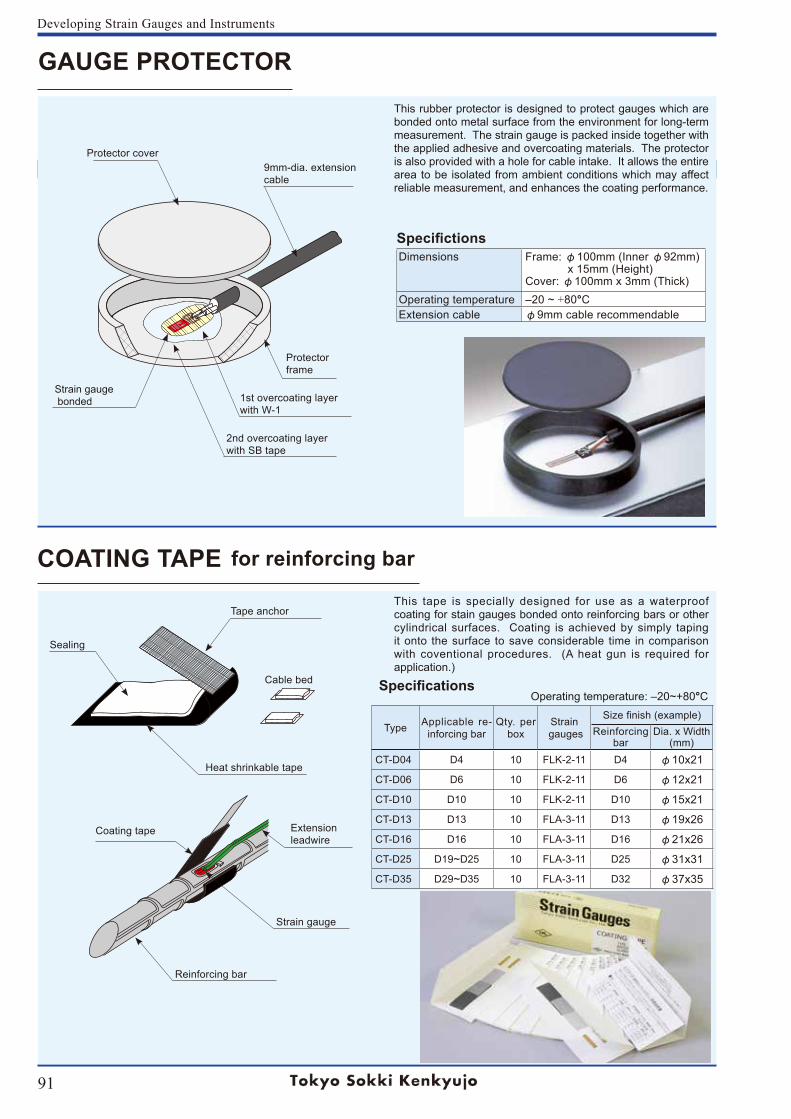
91
Developing Strain Gauges and Instruments
GAUGE PROTECTOR
COATING TAPE for reinforcing bar
This rubber protector is designed to protect gauges which are bonded onto metal surface from the environment for long-term measurement. The strain gauge is packed inside together with the applied adhesive and overcoating materials. The protector is also provided with a hole for cable intake. It allows the entire area to be isolated from ambient conditions which may affect reliable measurement, and enhances the coating performance.
SpecifictionsDimensions Frame: φ100mm (Inner φ92mm)
x 15mm (Height)Cover: φ100mm x 3mm (Thick)
Operating temperature ‒20 ~ +80°CExtension cable φ9mm cable recommendable
This tape is specially designed for use as a waterproof coating for stain gauges bonded onto reinforcing bars or other cylindrical surfaces. Coating is achieved by simply taping it onto the surface to save considerable time in comparison with coventional procedures. (A heat gun is required for application.)
Specifications Operating temperature: ‒20~+80°C
Type Applicable re-inforcing bar
Qty. per box
Strain gauges
Size finish (example)Reinforcing
barDia. x Width
(mm)CT-D04 D4 10 FLK-2-11 D4 φ10x21
CT-D06 D6 10 FLK-2-11 D6 φ12x21
CT-D10 D10 10 FLK-2-11 D10 φ15x21
CT-D13 D13 10 FLA-3-11 D13 φ19x26
CT-D16 D16 10 FLA-3-11 D16 φ21x26
CT-D25 D19~D25 10 FLA-3-11 D25 φ31x31
CT-D35 D29~D35 10 FLA-3-11 D32 φ37x35
Protector cover
Sealing
9mm-dia. extensioncable
Strain gauge bonded 1st overcoating layer
with W-1
2nd overcoating layerwith SB tape
Tape anchor
Cable bed
Coating tape
Reinforcing bar
Strain gauge
Extension leadwire
Protectorframe
Heat shrinkable tape
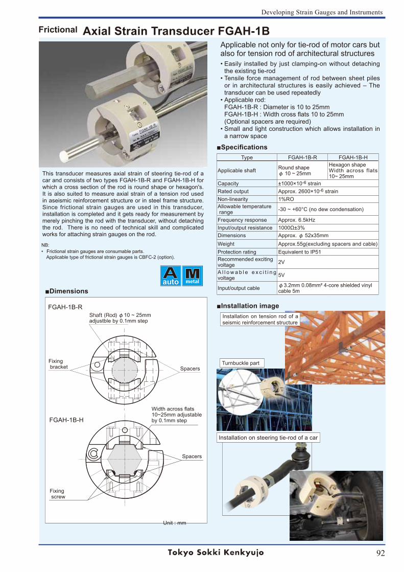
92
Developing Strain Gauges and Instruments
Installation image
Specifications
Dimensions
This transducer measures axial strain of steering tie-rod of a car and consists of two types FGAH-1B-R and FGAH-1B-H for which a cross section of the rod is round shape or hexagon's. It is also suited to measure axial strain of a tension rod used in aseismic reinforcement structure or in steel frame structure. Since frictional strain gauges are used in this transducer, installation is completed and it gets ready for measurement by merely pinching the rod with the transducer, without detaching the rod. There is no need of technical skill and complicated works for attaching strain gauges on the rod.
Applicable not only for tie-rod of motor cars but also for tension rod of architectural structures• Easily installed by just clamping-on without detaching
the existing tie-rod• Tensile force management of rod between sheet piles
or in architectural structures is easily achieved – The transducer can be used repeatedly
• Applicable rod: FGAH-1B-R : Diameter is 10 to 25mm FGAH-1B-H : Width cross flats 10 to 25mm (Optional spacers are required)
• Small and light construction which allows installation in a narrow space
Type FGAH-1B-R FGAH-1B-H
Applicable shaft Round shapeφ 10 ~ 25mm
Hexagon shapeWidth across flats 10~ 25mm
Capacity ±1000×10-6 strainRated output Approx. 2600×10-6 strainNon-linearity 1%ROAllowable temperature range -30 ~ +60°C (no dew condensation)
Frequency response Approx. 6.5kHzInput/output resistance 1000Ω±3%Dimensions Approx. φ 52x35mmWeight Approx.55g(excluding spacers and cable)Protection rating Equivalent to IP51Recommended excitingvoltage 2V
A l l o w a b l e e x c i t i n g voltage 5V
Input/output cable φ3.2mm 0.08mm² 4-core shielded vinylcable 5m
Shaft (Rod) φ10 ~ 25mm adjustble by 0.1mm step
SpacersFixing bracket
Turnbuckle part
Installation on tension rod of a seismic reinforcement structure
Frictional Axial Strain Transducer FGAH-1B
Unit : mm
NB:• Frictional strain gauges are consumable parts.
Applicable type of frictional strain gauges is CBFC-2 (option).
auto
Spacers
Width across flats10~25mm adjustableby 0.1mm step
Fixing screw
FGAH-1B-R
FGAH-1B-H
Installation on steering tie-rod of a car
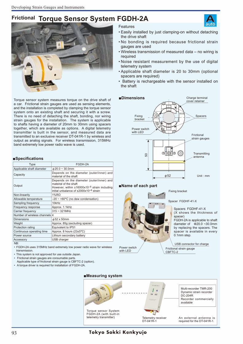
93
Developing Strain Gauges and Instruments
Torque sensor system measures torque on the drive shaft of a car. Frictional strain gauges are used as sensing elements, and the installation is completed by clamping the torque sensor system onto an existing shaft and securing it with a screw. There is no need of detaching the shaft, bonding, nor wiring strain gauges for the installation. The system is applicable to shafts having a diameter of 20mm to 30mm using spacers together, which are available as options. A digital telemetry transmitter is built in the sensor, and measured data are transmitted to an exclusive receiver DT-041R-1 by wireless and output as analog signals. For wireless transmission, 315MHz band extremely low power radio wave is used.
Features• Easily installed by just clamping-on without detaching
the drive shaft• No bonding is required because frictional strain
gauges are used• Wireless transmission of measured data – no wiring is
required• Noise resistant measurement by the use of digital
telemetry system• Applicable shaft diameter is 20 to 30mm (optional
spacers are required)• Battery is rechargeable with the sensor installed on
the shaft
ONOFF
Power switchwith LED
φ52
50
SpacersFixing bracket
Charge terminal cover retainer
Frictionalstrain gauges
Transmittingantenna
Spacer FGDHF-41-X
Fixing bracket
Power switchwith LED
Frictional strain gaugeCBFTC-2
Spacers FGDHF-41-X(X shows the thickness of spacer)FGDH-2A is applicable to shaft diameter of Φ20.0 ~30.0mm by replacing the spacers. The spacer is available in every 0.1mm step.
USB connector for charge
Name of each part
Dimensions
Type FGDH-2AApplicable shaft diameter φ20.0 ~ 30.0mm
Capacity Depends on the diameter (outer/inner) and material of the shaft
Output
Depends on the diameter (outer/inner) and mateiral of the shaftHowever, within ±16000x10‒6 strain including initial unbalance of ±2000x10‒6 strain
Non-linearity 1%ROAllowable temperature ‒20 ~ +60°C (no dew condensation)Sampling frequency 10kHzFrequency response Approx. 1.1kHzCarrier frequency 315 ~ 321MHzNumber of wireless channels 4Dimensions φ52 x 50mmWeight Approx. 85g (excluding spacer)Protection rating Equivalent to IP51Continuous operating time Approx. 8 hours (23±5°C)Power source Lithium secondary batteryAccessory USB chargerNB:• FGDH-2A uses 315MHz band extremely low power radio wave for wireless
transmission.• This system is not approved for use outside Japan.• Frictional strain gauges are consumable parts.
Applicable type of frictional strain gauge is CBFTC-2 (option).• A torque driver is required for installation of FGDH-2A.
Multi-recorder TMR-200Dynamic strain recorderDC-204RRecorder commercially available
Torque sensor System FGDH-2A (with built-in telemetry transmitter) Telemetry receiver
DT-041R-1An external antenna is required for the DT-041R-1.
Measuring system
Specifications
Unit : mm
autoFrictional Torque Sensor System FGDH-2A
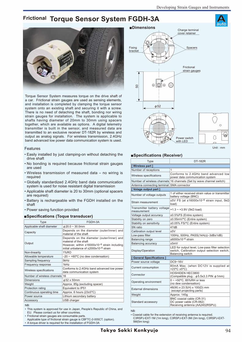
94
Developing Strain Gauges and Instruments
Torque Sensor System measures torque on the drive shaft of a car. Frictional strain gauges are used as sensing elements, and installation is completed by clamping the torque sensor system onto an existing shaft and securing it with a screw. There is no need of detaching the shaft, bonding nor wiring strain gauges for installation. The system is applicable to shafts having diameter of 20mm to 30mm using spacers together, which are available as options. A digital telemetry transmitter is built in the sensor, and measured data are transmitted to an exclusive receiver DT-182R by wireless and output as analog signals. For wireless transmission, 2.4GHz band advanced low power data communication system is used.
Features• Easily installed by just clamping-on without detaching the
drive shaft• No bonding is required because frictional strain gauges
are used• Wireless transmission of measured data – no wiring is
required • Globally standardized 2.4GHz band data communication
system is used for noise resistant digital transmission• Applicable shaft diameter is 20 to 30mm (optional spacers
are required)• Battery is rechargeable with the FGDH installed on the
shaft• Power saving function provided
SpacersFixing bracket
Charge terminal cover retainer
Power switchwith LED
φ52
50
Dimensions
Type FGDH-3AApplicable shaft diameter φ20.0 ~ 30.0mm
Capacity Depends on the diameter (outer/inner) and material of the shaft
Output
Depends on the diameter (outer/inner) and mateiral of the shaftHowever, within ±16000x10‒6 strain including initial unbalance of ±2000x10‒6 strain
Non-linearity 1%ROAllowable temperature ‒20 ~ +60°C (no dew condensation)Sampling frequency 5kHzFrequency response 1kHz
Wireless specifications Conforms to 2.4GHz band advanced low power data communication system
Number of wireless channels 16Dimensions φ52 x 50mmWeight Approx. 85g (excluding spacer)Protection rating Equivalent to IP51Continuous operating time Approx. 6 hours (23±5°C)Power source Lithium secondary batteryAccessory USB charger
Specifications (Toque transducer)
NB:• This system is approved for use in Japan, People’s Republic of China, and
EU. Please contact us for other countries.• Frictional strain gauges are consumable parts.
Applicable type of frictional strain gauge is CBFTC-2-005CT. (option).• A torque driver is required for the installation of FGDH-3A
Specifications (Receiver) Type DT-182R
[ Wireless part ]Number of receptions 1
Wireless specifications Conforms to 2.4GHz band advanced low power data communication system
Number of wireless channels 16 channels (Set by wave channel switch)Antenna connecting terminal SMA connector[ Volage output part ]
Number of voltage outputs 1 of either received strain value or transmitter battery voltage (BNC)
Strain measurement ±5V FS (at ±16000x10‒6 strain input, 5kΩ load)
Transmitter battery voltage measurement +1.3 ~ +3.9V (5kΩ load)
Voltage output accuracy ±0.5%FS (Entire system)Stability on zero ±0.55mV/°C (Entire system)Stability on sensitivity ±0.05% FS/°C (Entire system)SN ratio 47dBCalibration output level ±5VLow-pass filter 100Hz, 500Hz, PASS(1kHz)(‒3dB±1dB)Balancing range ±6000x10‒6 strainBalancing accuracy ±5mV
Display/OperationLED for output level, Low-pass filter selection switch, Calibration output selection switch, Balancing switch
[ General Specifications ]Power source voltage DC9~16V
Current consumption 80mA Max. (when DC12V is supplied at +23°C ±5°C)
Connector HOSHIDEN HEC3800 (Compatible plug : φ5.5x3.3 PIN φ1mm)
Operating environment 0 ~ +50°C, 85%RH or less (no dew condensation)
External dimensions 48(W) x 23.5(H) x 100(D) mm (except projecting parts)
Weight Approx. 140g
Standard accessoryBNC coaxial cable (CR-31)DC power cable (CR-062)Receiving antenna (AA2402RSPU)
NB: Coaxial cable for the extension of receiving antenna is required. C3RSPJ-EXT-1M (1m long), C3RSPJ-EXT-3M (3m long), C3RSPJ-EXT- 5M(5m long)
Unit : mm
Frictionalstrain gauges
autoFrictional Torque Sensor System FGDH-3A
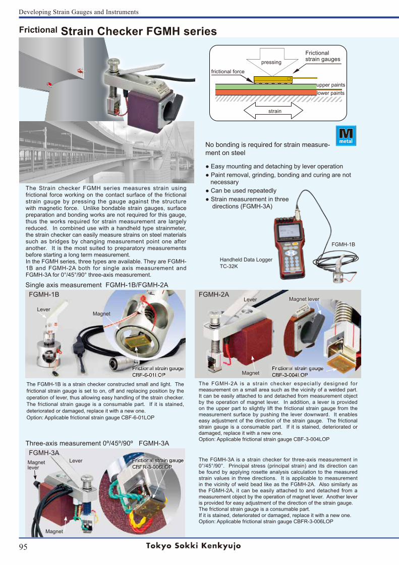
95
Developing Strain Gauges and Instruments
The Strain checker FGMH series measures strain using frictional force working on the contact surface of the frictional strain gauge by pressing the gauge against the structure with magnetic force. Unlike bondable strain gauges, surface preparation and bonding works are not required for this gauge, thus the works required for strain measurement are largely reduced. In combined use with a handheld type strainmeter, the strain checker can easily measure strains on steel materials such as bridges by changing measurement point one after another. It is the most suited to preparatory measurements before starting a long term measurement.In the FGMH series, three types are available. They are FGMH-1B and FGMH-2A both for single axis measurement and FGMH-3A for 0°/45°/90° three-axis measurement.
upper paints
strain
pressing
lower paints
frictional force
Frictional strain gauges
No bonding is required for strain measure-ment on steel
Easy mounting and detaching by lever operation Paint removal, grinding, bonding and curing are not necessary Can be used repeatedly Strain measurement in three directions (FGMH-3A)
The FGMH-1B is a strain checker constructed small and light. The frictional strain gauge is set to on, off and replacing position by the operation of lever, thus allowing easy handling of the strain checker. The frictional strain gauge is a consumable part. If it is stained, deteriorated or damaged, replace it with a new one.Option: Applicable frictional strain gauge CBF-6-01LOP
The FGMH-2A is a strain checker especially designed for measurement on a small area such as the vicinity of a welded part. It can be easily attached to and detached from measurement object by the operation of magnet lever. In addition, a lever is provided on the upper part to slightly lift the frictional strain gauge from the measurement surface by pushing the lever downward. It enables easy adjustment of the direction of the strain gauge. The frictional strain gauge is a consumable part. If it is stained, deteriorated or damaged, replace it with a new one.Option: Applicable frictional strain gauge CBF-3-004LOP
The FGMH-3A is a strain checker for three-axis measurement in 0°/45°/90°. Principal stress (principal strain) and its direction can be found by applying rosette analysis calculation to the measured strain values in three directions. It is applicable to measurement in the vicinity of weld bead like as the FGMH-2A. Also similarly as the FGMH-2A, it can be easily attached to and detached from a measurement object by the operation of magnet lever. Another lever is provided for easy adjustment of the direction of the strain gauge.The frictional strain gauge is a consumable part.If it is stained, deteriorated or damaged, replace it with a new one.Option: Applicable frictional strain gauge CBFR-3-006LOP
Lever
FGMH-1B
FGMH-1B
Magnet
Magnet
Magnet
Handheld Data Logger TC-32K
Magnet lever
Lever
FGMH-2A
FGMH-3A
Single axis measurement FGMH-1B/FGMH-2A
Three-axis measurement 0º/45º/90º FGMH-3A
Magnetlever
Lever
Frictional Strain Checker FGMH series
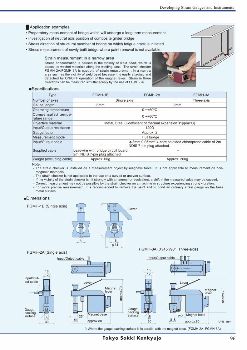
96
Developing Strain Gauges and Instruments
Application examples Preparatory measurement of bridge which will undergo a long term measurement Investigation of neutral axis position of composite girder bridge Stress direction of structural member of bridge on which fatigue crack is initiated Stress measurement of newly built bridge where paint removal is not available.
Type FGMH-1B FGMH-2A FGMH-3ANumber of axes Single axis Three-axisGauge length 6mm 3mmOperating temperature 0 ~+60ºCCompensated tempe-rature range 0 ~+60ºC
Objective material Metal, Steel (Coefficient of thermal expansion 11ppm/ºC)Input/Output resistance 120ΩGauge factor Approx. 2Measurement mode Full bridgeInput/Output cable ‒ φ3mm 0.05mm² 4-core shielded chloroprene cable of 2m
NDIS 7-pin plug attachedSupplied cable Leadwire with bridge circuit board
2m, NDIS 7-pin plug attached ‒
Weight (excluding cable) Approx. 60g Approx. 260gNote:• The strain checker is installed on a measurement object by magnetic force. It is not applicable to measurement on non-
magnetic materials.• The strain checker is not applicable to the use on a curved or uneven surface.• If the vicinity of the strain checker is hit strongly with a hammer or equivalent, a shift in the measured value may be caused.• Correct measurement may not be possilble by the strain checker on a machine or structure experiencing strong vibration.• For more precise measurement, it is recommended to remove the paint and to bond an ordinary strain gauge on the base
metal surface.
Specifications
OFF
ON
Input/Output cable
*: Where the gauge backing surface is in parallel with the magnet base. (FGMH-2A, FGMH-3A)
30 approx.80
8
8
18φ34
8 8
1812
25*
1812
308 8
1025*
Input/Output cable
appr
ox.7
0
appr
ox.7
0
approx.80
Input/Out-put cable
Gaugebacking surface
Gaugebacking surface
FGMH-2A (Single axis)
FGMH-1B (Single axis)
FGMH-3A (0º/45º/90º Three-axis)
Dimensions
Magnet baseMagnet base
Unit : mm
Magnet lever
Lever
Magnet lever
Lever
Lever
Strain measurement in a narrow areaStress concentration is caused in the vicinity of weld bead, which is deposit of welded materials along the welding pass. The strain checker FGMH-2A/FGMH-3A is capable of strain measurement in a narrow area such as the vicinity of weld bead because it is easily attached and detached by ON/OFF operation of the magnet lever. Strain in three directions can be measured simultaneously by the use of FGMH-3A.
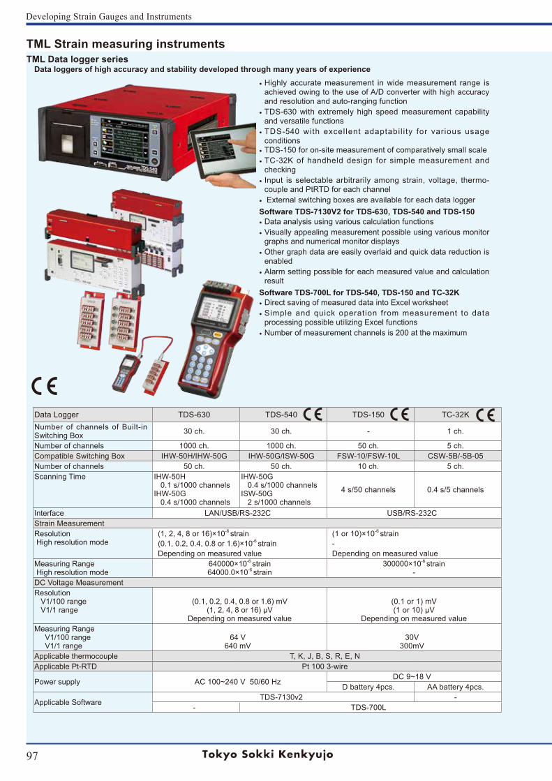
97
Developing Strain Gauges and Instruments
TML Strain measuring instruments
• Highly accurate measurement in wide measurement range is achieved owing to the use of A/D converter with high accuracy and resolution and auto-ranging function
• TDS-630 with extremely high speed measurement capability and versatile functions
• TDS-540 with excel lent adaptabi l i ty for various usage conditions
• TDS-150 for on-site measurement of comparatively small scale• TC-32K of handheld design for simple measurement and
checking• Input is selectable arbitrarily among strain, voltage, thermo-
couple and PtRTD for each channel• External switching boxes are available for each data loggerSoftware TDS-7130V2 for TDS-630, TDS-540 and TDS-150• Data analysis using various calculation functions• Visually appealing measurement possible using various monitor
graphs and numerical monitor displays• Other graph data are easily overlaid and quick data reduction is
enabled• Alarm setting possible for each measured value and calculation
result Software TDS-700L for TDS-540, TDS-150 and TC-32K• Direct saving of measured data into Excel worksheet• Simple and quick operation from measurement to data
processing possible utilizing Excel functions • Number of measurement channels is 200 at the maximum
TML Data logger series Data loggers of high accuracy and stability developed through many years of experience
Data Logger TDS-630 TDS-540 TDS-150 TC-32KNumber of channels of Built-in Switching Box 30 ch. 30 ch. - 1 ch.
Number of channels 1000 ch. 1000 ch. 50 ch. 5 ch.Compatible Switching Box IHW-50H/IHW-50G IHW-50G/ISW-50G FSW-10/FSW-10L CSW-5B/-5B-05Number of channels 50 ch. 50 ch. 10 ch. 5 ch.Scanning Time IHW-50H
0.1 s/1000 channelsIHW-50G 0.4 s/1000 channels
IHW-50G 0.4 s/1000 channelsISW-50G 2 s/1000 channels
4 s/50 channels 0.4 s/5 channels
Interface LAN/USB/RS-232C USB/RS-232CStrain MeasurementResolution High resolution mode
(1, 2, 4, 8 or 16)×10-6 strain(0.1, 0.2, 0.4, 0.8 or 1.6)×10-6 strainDepending on measured value
(1 or 10)×10-6 strain-Depending on measured value
Measuring Range High resolution mode
640000×10-6 strain64000.0×10-6 strain
300000×10-6 strain-
DC Voltage MeasurementResolution V1/100 range V1/1 range
(0.1, 0.2, 0.4, 0.8 or 1.6) mV(1, 2, 4, 8 or 16) μV
Depending on measured value
(0.1 or 1) mV(1 or 10) μV
Depending on measured valueMeasuring Range V1/100 range V1/1 range
64 V640 mV
30V300mV
Applicable thermocouple T, K, J, B, S, R, E, NApplicable Pt-RTD Pt 100 3-wire
Power supply AC 100~240 V 50/60 HzDC 9~18 V
D battery 4pcs. AA battery 4pcs.
Applicable SoftwareTDS-7130v2 -
- TDS-700L
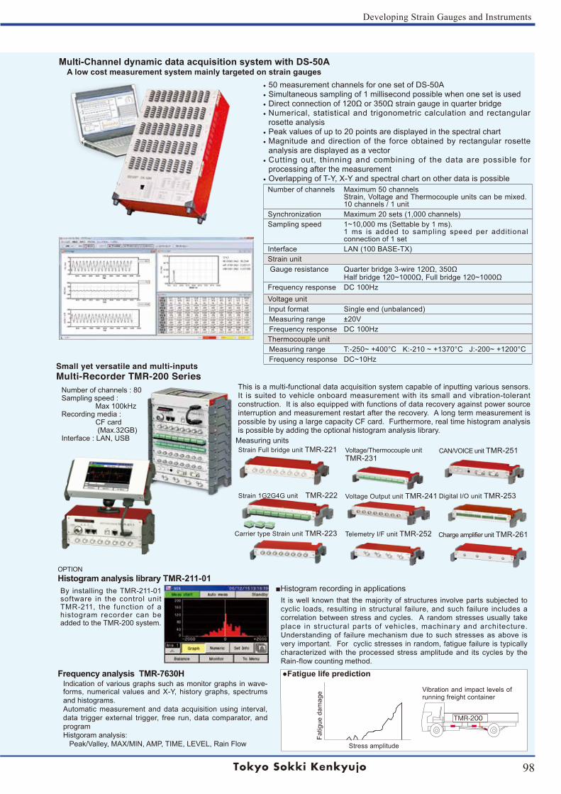
98
Developing Strain Gauges and Instruments
Small yet versatile and multi-inputsMulti-Recorder TMR-200 Series
Strain Full bridge unit TMR-221
Strain 1G2G4G unit TMR-222
Voltage/Thermocouple unit TMR-231
Voltage Output unit TMR-241
Telemetry I/F unit TMR-252
CAN/VOICE unit TMR-251
Digital I/O unit TMR-253
Charge amplifier unit TMR-261Carrier type Strain unit TMR-223
Measuring units
This is a multi-functional data acquisition system capable of inputting various sensors. It is suited to vehicle onboard measurement with its small and vibration-tolerant construction. It is also equipped with functions of data recovery against power source interruption and measurement restart after the recovery. A long term measurement is possible by using a large capacity CF card. Furthermore, real time histogram analysis is possible by adding the optional histogram analysis library.
Histogram recording in applications
TMR-200
Stress amplitude
Vibration and impact levels of running freight container
Fatig
ue d
amag
e
It is well known that the majority of structures involve parts subjected to cyclic loads, resulting in structural failure, and such failure includes a correlation between stress and cycles. A random stresses usually take place in structural par ts of vehicles, machinary and architecture. Understanding of failure mechanism due to such stresses as above is very important. For cyclic stresses in random, fatigue failure is typically characterized with the processed stress amplitude and its cycles by the Rain-flow counting method.
Frequency analysis TMR-7630HIndication of various graphs such as monitor graphs in wave-forms, numerical values and X-Y, history graphs, spectrums and histograms. Automatic measurement and data acquisition using interval, data trigger external trigger, free run, data comparator, and programHistgoram analysis: Peak/Valley, MAX/MIN, AMP, TIME, LEVEL, Rain Flow
Number of channels : 80Sampling speed : Max 100kHzRecording media : CF card (Max.32GB)Interface : LAN, USB
Fatigue life prediction
By installing the TMR-211-01 software in the control unit TMR-211, the function of a histogram recorder can be added to the TMR-200 system.
OPTIONHistogram analysis library TMR-211-01
Multi-Channel dynamic data acquisition system with DS-50A A low cost measurement system mainly targeted on strain gauges
• 50 measurement channels for one set of DS-50A • Simultaneous sampling of 1 millisecond possible when one set is used• Direct connection of 120Ω or 350Ω strain gauge in quarter bridge• Numerical, statistical and trigonometric calculation and rectangular
rosette analysis• Peak values of up to 20 points are displayed in the spectral chart• Magnitude and direction of the force obtained by rectangular rosette
analysis are displayed as a vector • Cutting out, thinning and combining of the data are possible for
processing after the measurement• Overlapping of T-Y, X-Y and spectral chart on other data is possible
Number of channels Maximum 50 channelsStrain, Voltage and Thermocouple units can be mixed. 10 channels / 1 unit
Synchronization Maximum 20 sets (1,000 channels)Sampling speed 1~10,000 ms (Settable by 1 ms).
1 ms is added to sampling speed per additional connection of 1 set
Interface LAN (100 BASE-TX)Strain unit Gauge resistance Quarter bridge 3-wire 120Ω, 350Ω
Half bridge 120~1000Ω, Full bridge 120~1000ΩFrequency response DC 100HzVoltage unit Input format Single end (unbalanced)Measuring range ±20VFrequency response DC 100HzThermocouple unitMeasuring range T:-250~ +400°C K:-210 ~ +1370°C J:-200~ +1200°C Frequency response DC~10Hz

8-2, Minami-Ohi 6-Chome, Shinagawa-Ku, Tokyo 140-8560, JAPANTEL: +81-3-3763-5614 FAX: +81-3-3763-5713email address: [email protected]


![Tml ppt.[1]](https://static.documents.pub/doc/80x56/553804f14a79593a698b46d1/tml-ppt1.jpg)


