22
TMP006 Customer Training Applications Team Sensing Products
| Date post: | 18-Dec-2015 |
| Category: |
Documents |
| Upload: | bertha-baker |
| View: | 221 times |
| Download: | 6 times |

TMP006 Customer Training
Applications Team
Sensing Products

ThermopileThermocouple
-
+
Heat Absorber Cold Junction
What is a Thermocouple / Thermopile
Thot
Thot
Thot
Thot
TcoldThot
Tcold
+
-
Heat Absorber
Heat Sink
Vout Vout
Vout = G x (Thot – Tcold)
G: Seebeck Constant
Vout = n x G x (Thot – Tcold)
G: Seebeck Constant

Heat Transfer (1): Conduction
• Conduction: Heat is transferred through direct touch.– Example: Touching a hot cup of coffee

Heat Transfer (2): Convection
• Convection: Heat is transferred by a moving liquid or gas.– Example: Fan cooling

Heat Transfer (3): Radiation
• Radiation: Heat is transferred by waves (photons)– Example: The warmth you feel from the sun– The amount of energy radiated is dependent on the absolute (Kelvin)
temperature of the object.

Device Principle of Operation
Object
PCB
TMP006
Infrared Radiation
TMP006 at its core is a heat sensor. It converts the heat being transferred to a voltage.

PCB Recommended Layout
• The sensor at it’s core is a heat sensor and is sensitive to conduction and convection in addition to radiation.
• Recommended PCB layout isolates the sensor from the rest of the PCB
Via Connecting to Circuit
Copper Dot
Thermal Break
GND
TMP006 Conduction & Convection Offsets
• The sensor, is a heat sensor at its core. It will detect heat from all three sources: conduction, convection, and radiation.
• The signal created by heat conduction and convection is relatively small in a setup with the recommended PCB layout but it is not zero.
• Calibration is needed to cancel out remaining offsets

Case
Field of View Consideration (1)
• For best performance it is recommended that the diameter of object is 4 times the distance to the TMP006 sensor.
• d = h – 250µm
• object size ≥ 4×d
PCB
TMP006
distance = d
object size ≥ 4d
h
Field of View Consideration (2)
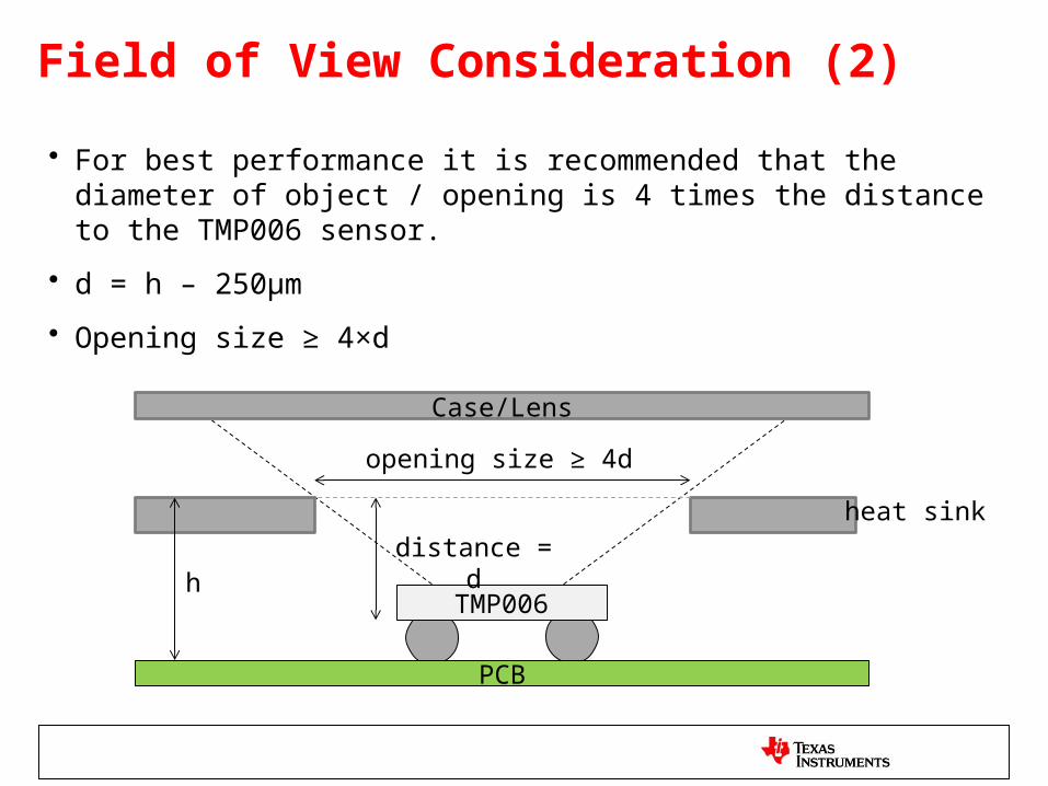
• For best performance it is recommended that the diameter of object / opening is 4 times the distance to the TMP006 sensor.
• d = h – 250µm
• Opening size ≥ 4×d
PCB
TMP006
distance = d
opening size ≥ 4d
h
Case/Lens
heat sink

Emissivity Considerations
• Not all objects emit the same amount of energy at the same temperature.
• Emissivity is the ratio of energy radiated by an emitter to the theoretical ideal emitter. Emissivity is always less than one.
• Since the emissivity may change for different systems, then the system gain will need to be calibrated.

TMP006 Equation
2210 1 refdierefdie TTaTTaSS
2210 refdierefdieos TTbTTbbV
22 osobjosobjobj VVcVVVf
44 )(
S
VfTT obj
dieobj
System independent: No need to calibrate
Models voltage offset due to conduction & convection. System dependent & needs calibration
Needs calibration. Depends on field of view and emissivity of object
System independent: No need to calibrate

Transient Correction Basics
• Rth Thermal resistance of thermopile
• Cth Thermal capacitance of thermopile
Thermopile
RthCth
Thot Tcold
• The hot junction is isolated from the rest of the sensor by the sensor’s thermal
resistivity
• When the sensor’s cold junction temperature is changed through heat conduction
from the outside, the hot junction follows, but is delayed by a time constant
• This effect can be modeled with a first order RC filter that delays the hot junction
relative to the sensor substrate temperature
Thot
Tcold
+
-
Heat Absorber
Heat Sink
Vout

Transient Error Example
Thot
Tcold
Thot
Tcold
time time
Tem
pera
ture
Tem
pera
ture

Transient Correction Basics (2)
/ C) (V.CRSeebeckα
t
TV
CRSeebeckt
TV
CRt
TSeebeckV
-thth
ColdErr
ththCold
Err
ththCold
Err
sec10962 4
Alpha is a constant which corresponds to the multiplication of Seebeck constant and the thermal time constant
A temperature gradient is created on the thermopile during transients that is proportional the slope of the transient itself.This gradient generates a voltage error through the Seebeck effect.

Effect of Transient Correction
Wit
h t
ran
sien
t c
orr
ecti
on
Wit
ho
ut
tran
sien
t co
rrec
tio
n

Coefficient Calibration
• Coefficients that get calibrated are: S0, b0, b1 & b2
• Before calibrating the coefficients, transient correction should be applied to the sensor’s output voltage to cancel out the transient effects.
• At this point in time it is recommended that the customer send us the data of their system and we will provided a custom set of “b” coefficients for optimum accuracy.
• An automatic calibration software is being developed at this point and should be available for customer use in the near future

Setting Up The System For Calibration
• For calibration: the data from the reference: Tobj as well as the TMP006 data: Tdie & Vout need to be collected simultaneously.
Object
PCB
TMP006
Reference Temperature Sensor (Example: TMP112)
Glued to object using thermal epoxy

Calibrating S0
221
41
42
120
2210
121241
42
21
21
21
2
2242
42
1
1141
41
2210
2210
1
1
if
1
REFdieREFdieobjobj
objobj
REFdieREFdie
objobjobjobjobjobj
ososos
diedie
osobjdieobj
osobjdieobj
REFdieREFdieos
REFdieREFdie
TTaTTaTT
VVS
TTaTTaS
VV
S
VVTT
SSS
VVV
TT
S
VVTT
S
VVTT
TTbTTbbV
TTaTTaSS
To be able to accurately calibrate S0 you need at least two points with the same Tdie values but different Tobj values.More than one measurement is recommended to reduce the effect of noise

Calibrating “b” Coefficients
• The residual offset based on the calibrated S0 value is calculated according to the equation above.
• The calculated offset is drawn versus (Tdie – Tref) and a second order curve fit for the data is done to calculate the b0, b1 and b2 coefficients.
44
44
dieobjobjos
osobjdieobj
TTSVV
S
VVTT
2210 REFdieREFdieos TTbTTbbV
2nd order curve fit(use excel)Coefficients of curve fit are b0, b1 and b2
Vos
= V
obj –
S(T
obj4
– T
die4 )
Tdie – Tref

Importance of the Number and Range of Points
• The larger the number of points the lower the effect of noise.
• The further apart the points are the better the correction.
Actual device behavior
Calibrated curve based on only middle three points
Points collected don’t exactly match the actual curve due to noise
x-axis
y-ax
is
Error at the extreme points

Default Versus Calibrated CoefficientsD
efau
lt c
oef
fici
ents
Cal
ibra
ted
co
effi
cien
ts


![[REMOTE SENSING] 3-PM Remote Sensing](https://static.documents.pub/doc/80x56/61f2bbb282fa78206228d9e2/remote-sensing-3-pm-remote-sensing.jpg)


