DSP28 - DSP/BIOS 12 - 1 Introduction Chapter 12 introduces Texas Instruments Built-In Operating System (“BIOS”) for Digital Signal Processors - “DSP/BIOS”. This firmware will allow you to use a range of a Real Time Operating System (“RTOS”) features in an embedded control application. It is not the intention of this module to cover the theory of Operating Systems and the specific demands of a real time control applications. To be able to work with all options of DSP/BIOS it will be necessary for you to enrol in additional classes about this topic at your university. When you have completed these classes, it is highly recommended to return to this module after you are familiar with the theory of multi processing and real time control. With this knowledge, you can enhance the examples shown in this chapter to their full extent. We will now have a brief look into the essentials of DSP/BIOS. We shall start with the introduction of core terms and definitions of a real time system: • What is a RTOS? • What is a task? • What is the task state model? • What is a scheduler? Then we will discuss and use the BIOS system configuration tools to simplify the setup of a C28x code project. Next, we will take a closer look to some of the basic concepts of DSP/BIOS: • Scheduler • Hardware Interrupts (HWI) • Software Interrupts (SWI) • Periodic Functions (PRD) At the end of this module we will return to the laboratory and modify one of our existing programs to use both the DSP/BIOS configuration tool and a periodic function. C28x DSP/BIOS
Transcript
DSP28 - DSP/BIOS 12 - 1
Introduction Chapter 12 introduces Texas Instruments Built-In Operating System (“BIOS”) for Digital Signal Processors - “DSP/BIOS”. This firmware will allow you to use a range of a Real Time Operating System (“RTOS”) features in an embedded control application. It is not the intention of this module to cover the theory of Operating Systems and the specific demands of a real time control applications. To be able to work with all options of DSP/BIOS it will be necessary for you to enrol in additional classes about this topic at your university. When you have completed these classes, it is highly recommended to return to this module after you are familiar with the theory of multi processing and real time control. With this knowledge, you can enhance the examples shown in this chapter to their full extent.
We will now have a brief look into the essentials of DSP/BIOS. We shall start with the introduction of core terms and definitions of a real time system:
• What is a RTOS?
• What is a task?
• What is the task state model?
• What is a scheduler?
Then we will discuss and use the BIOS system configuration tools to simplify the setup of a C28x code project.
Next, we will take a closer look to some of the basic concepts of DSP/BIOS:
• Scheduler
• Hardware Interrupts (HWI)
• Software Interrupts (SWI)
• Periodic Functions (PRD)
At the end of this module we will return to the laboratory and modify one of our existing programs to use both the DSP/BIOS configuration tool and a periodic function.
Introduction ...........................................................................................................................................12-1 Module Topics........................................................................................................................................12-2 Real Time Operating System..................................................................................................................12-3 A RTOS - Task........................................................................................................................................12-4 Task State Model....................................................................................................................................12-5 The RTOS - Scheduler............................................................................................................................12-7 Texas Instruments DSP/BIOS ................................................................................................................12-8 DSP/BIOS Configuration Tool.............................................................................................................12-10 DSP/BIOS Task Groups .......................................................................................................................12-11
Real-Time Analysis Tool ......................................................................................................................12-19 DSP/BIOS API .....................................................................................................................................12-20 Lab Exercise 12....................................................................................................................................12-21
Objective .........................................................................................................................................12-21 Procedure.........................................................................................................................................12-21 Open Files, Create Project File........................................................................................................12-21 Project Build Options ......................................................................................................................12-22 Modify Source Code........................................................................................................................12-23 Edit DSP/BIOS Configuration.........................................................................................................12-23 Build the project ..............................................................................................................................12-25 Test the code....................................................................................................................................12-25 Potential Solution for function “led_runner”:..................................................................................12-26
Real Time Operating System
DSP28 - DSP/BIOS 12 - 3
Real Time Operating System You are probably familiar with the basics of the operating system (OS) of your PC. One of the typical features of this OS is the ability to start and work on different processes simultaneously. You can open your word processor to edit a document and at the same time you can browse the web in another application process or you can check your emails. The term for this type of OS is “multi tasking”. The more processes you open the more difficult it will become for your OS to respond in time. Sometimes one of your processes will be ‘blocked’ for a while before it continues. It becomes more difficult for the OS if dedicated hardware interactions are involved, like burning a CD/DVD. In these cases, your application probably gives out a meek recommendation like: “Do not start any other application now…” to assure that its own procedure will be completed in time.
In short, this type of OS does not guarantee any completion time for a process! Sometimes a process is not completed at all; you are no doubt familiar with the keys “CTRL-ALT-DEL”.
Now imagine an embedded control application such as an autopilot of an airplane or a car braking system controlled by this type of operating system.
For this type of application, we need another type of OS that will guarantee a time line for all processes involved. We also need to know a “worst case response time” for all interactions and event processing of the control system - a “Real Time Operating System”
12 12 -- 22
Real Time Operating Systems (RTOS)Real Time Operating Systems (RTOS)
Particular class of operating systems for Particular class of operating systems for digital processor systemsdigital processor systemsCapable of serving multiple user tasks at one Capable of serving multiple user tasks at one time ( “multitime ( “multi--task OS”)task OS”)For all tasks in a running system it is For all tasks in a running system it is guaranteed, that random external events in guaranteed, that random external events in the environment of each individual task will the environment of each individual task will be serviced in a given time ( “Worst Case be serviced in a given time ( “Worst Case Response Time”).Response Time”).All tasks must be served simultaneously All tasks must be served simultaneously (“multi(“multi--task OS”) AND timely (“RTOS”)task OS”) AND timely (“RTOS”)RTOS are very popular in embedded controlRTOS are very popular in embedded control
What is a RTOS?What is a RTOS?
A RTOS - Task
12 - 4 DSP28 - DSP/BIOS
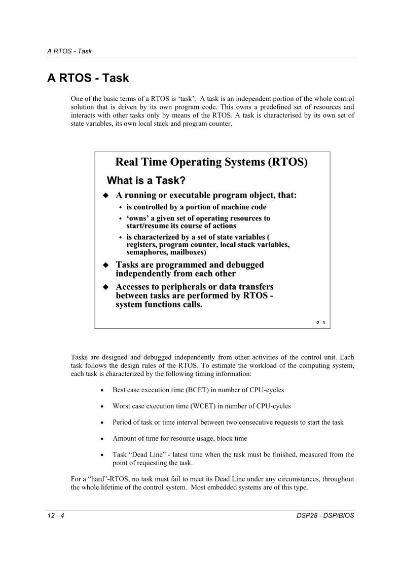
A RTOS - Task One of the basic terms of a RTOS is ‘task’. A task is an independent portion of the whole control solution that is driven by its own program code. This owns a predefined set of resources and interacts with other tasks only by means of the RTOS. A task is characterised by its own set of state variables, its own local stack and program counter.
12 12 -- 33
Real Time Operating Systems (RTOS)Real Time Operating Systems (RTOS)
A running or executable program object, that:A running or executable program object, that:is controlled by a portion of machine codeis controlled by a portion of machine code‘owns’ a given set of operating resources to ‘owns’ a given set of operating resources to start/resume its course of actions start/resume its course of actions is characterized by a set of state variables ( is characterized by a set of state variables ( registers, program counter, local stack variables, registers, program counter, local stack variables, semaphores, mailboxes)semaphores, mailboxes)
Tasks are programmed and debugged Tasks are programmed and debugged independently from each other independently from each other Accesses to peripherals or data transfers Accesses to peripherals or data transfers between tasks are performed by RTOS between tasks are performed by RTOS --system functions calls.system functions calls.
What is a Task?What is a Task?
Tasks are designed and debugged independently from other activities of the control unit. Each task follows the design rules of the RTOS. To estimate the workload of the computing system, each task is characterized by the following timing information:
• Best case execution time (BCET) in number of CPU-cycles
• Worst case execution time (WCET) in number of CPU-cycles
• Period of task or time interval between two consecutive requests to start the task
• Amount of time for resource usage, block time
• Task “Dead Line” - latest time when the task must be finished, measured from the point of requesting the task.
For a “hard”-RTOS, no task must fail to meet its Dead Line under any circumstances, throughout the whole lifetime of the control system. Most embedded systems are of this type.
Task State Model
DSP28 - DSP/BIOS 12 - 5
Task State Model Each task will be in one of the states given in the task state model (see slide 12-4). The RTOS takes control of the current status and possible transitions for each individual state.
12 12 -- 44
Real Time Operating Systems (RTOS)Real Time Operating Systems (RTOS)
Each task can reside in one of the following Each task can reside in one of the following states:states:
What is a TaskWhat is a Task-- State State -- Model?Model?
existent
not existent
ready
completedblocked
running
1
2 3
4
5
6
7
8
For explanation of arrows 1-8 see next slide
The states are:
• Existent - The task is installed in the control system but not yet activated.
• Ready - The task is activated and ready for running. It owns all necessary resources but the processor.
• Running - The task is currently executing
• Blocked - The task is waiting for a resource, a message, a signal or an event, which has not yet occurred.
• Completed – The task has terminated and awaits a new activation.
• Not Existent – The task has been cancelled permanently.
Task State Model
12 - 6 DSP28 - DSP/BIOS
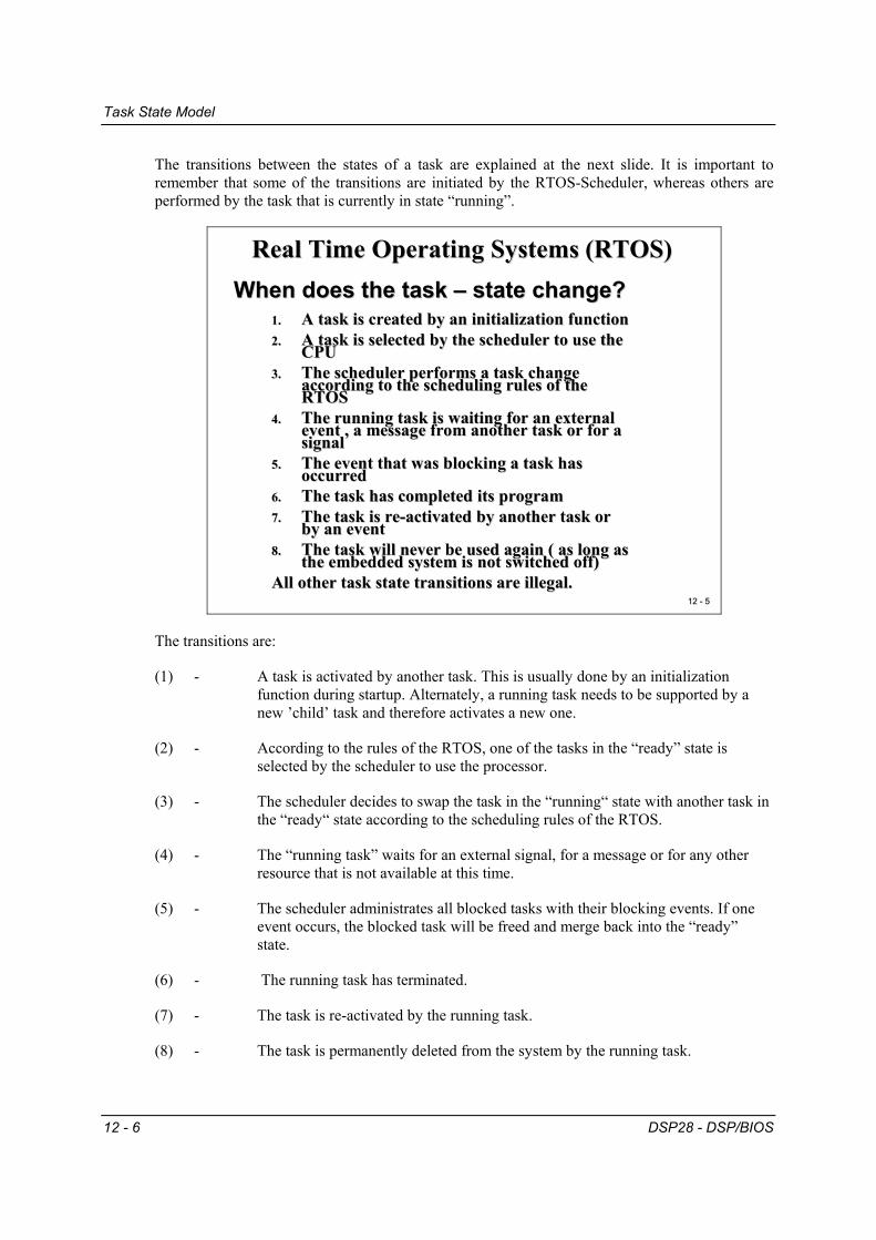
The transitions between the states of a task are explained at the next slide. It is important to remember that some of the transitions are initiated by the RTOS-Scheduler, whereas others are performed by the task that is currently in state “running”.
12 12 -- 55
Real Time Operating Systems (RTOS)Real Time Operating Systems (RTOS)
1.1. A task is created by an initialization functionA task is created by an initialization function2.2. A task is selected by the scheduler to use the A task is selected by the scheduler to use the
CPUCPU3.3. The scheduler performs a task change The scheduler performs a task change
according to the scheduling rules of the according to the scheduling rules of the RTOSRTOS
4.4. The running task is waiting for an external The running task is waiting for an external event , a message from another task or for a event , a message from another task or for a signalsignal
5.5. The event that was blocking a task has The event that was blocking a task has occurredoccurred
6.6. The task has completed its programThe task has completed its program7.7. The task is reThe task is re--activated by another task or activated by another task or
by an eventby an event8.8. The task will never be used again ( as long as The task will never be used again ( as long as
the embedded system is not switched off)the embedded system is not switched off)All other task state transitions are illegal. All other task state transitions are illegal.
When does the task When does the task –– state change?state change?
The transitions are:
(1) - A task is activated by another task. This is usually done by an initialization function during startup. Alternately, a running task needs to be supported by a new ’child’ task and therefore activates a new one.
(2) - According to the rules of the RTOS, one of the tasks in the “ready” state is selected by the scheduler to use the processor.
(3) - The scheduler decides to swap the task in the “running“ state with another task in the “ready“ state according to the scheduling rules of the RTOS.
(4) - The “running task” waits for an external signal, for a message or for any other resource that is not available at this time.
(5) - The scheduler administrates all blocked tasks with their blocking events. If one event occurs, the blocked task will be freed and merge back into the “ready” state.
(6) - The running task has terminated.
(7) - The task is re-activated by the running task.
(8) - The task is permanently deleted from the system by the running task.
The RTOS - Scheduler
DSP28 - DSP/BIOS 12 - 7
The RTOS - Scheduler One of the core modules of a RTOS is the scheduler. As the name implies, it schedules the execution of all tasks in a control system. It uses the task state model and the rules of the RTOS to work out how to handle multiple requests at one time. The main task of a RTOS-Scheduler is to interleave all tasks in state “ready”, so that each individual task is able to meet its specified dead line.
12 12 -- 66
Real Time Operating Systems (RTOS)Real Time Operating Systems (RTOS)
An important part of the RTOS that schedules the An important part of the RTOS that schedules the sequence of task execution phases and the change of sequence of task execution phases and the change of task statestask statesTwo basic operating modes for schedulers:Two basic operating modes for schedulers:
time slice mode time slice mode -- computing time is assigned to tasks in a computing time is assigned to tasks in a predefined amount of processor timepredefined amount of processor timepriority mode priority mode –– computing time is assigned to tasks computing time is assigned to tasks according to the priority of each task in the system. If a according to the priority of each task in the system. If a task with higher priority gets into status ‘ready’ the task with higher priority gets into status ‘ready’ the running task will be prerunning task will be pre--empted. empted. combined versions between precombined versions between pre--emptive and time slice emptive and time slice schedulers are also possibleschedulers are also possible
What is a Task What is a Task -- Scheduler?Scheduler?
A scheduler is no magic trick; it follows strict rules that were defined during the system configuration of the embedded system. Depending on the ability of the RTOS, we can choose between different options to tailor the scheduler. In general, there are two basic operating modes for the scheduling rules:
• Time Slice Mode - CPU time is granted to the tasks in fixed amounts of time. If the slice was consumed by the task before it could finish its operation the next “ready” task will be selected by the scheduler. The old task is suspended and will be added back at the end of the waiting list in state “ready”. It will resume its operation when the next slice is granted by the scheduler.
• Priority Mode - The scheduler uses the priority of a task to perform task switches. If there is a task in state “ready” with a higher priority than the running task, the scheduler will swap the two tasks. Some RTOS allow dynamic change of the priority depending on the current situation of the control system, others use static priorities. Common rules are “Dead Line Monotonic”, “Rate Monotonic”, “Earliest Dead Line First” or “Least Laxity”.
Texas Instruments DSP/BIOS
12 - 8 DSP28 - DSP/BIOS
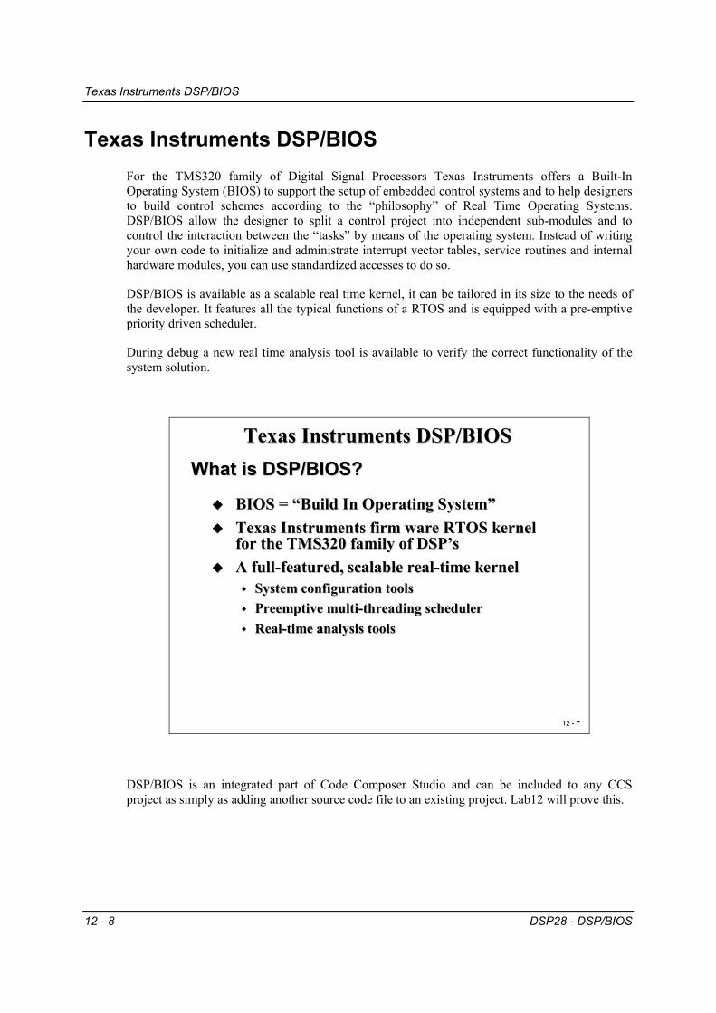
Texas Instruments DSP/BIOS For the TMS320 family of Digital Signal Processors Texas Instruments offers a Built-In Operating System (BIOS) to support the setup of embedded control systems and to help designers to build control schemes according to the “philosophy” of Real Time Operating Systems. DSP/BIOS allow the designer to split a control project into independent sub-modules and to control the interaction between the “tasks” by means of the operating system. Instead of writing your own code to initialize and administrate interrupt vector tables, service routines and internal hardware modules, you can use standardized accesses to do so.
DSP/BIOS is available as a scalable real time kernel, it can be tailored in its size to the needs of the developer. It features all the typical functions of a RTOS and is equipped with a pre-emptive priority driven scheduler.
During debug a new real time analysis tool is available to verify the correct functionality of the system solution.
BIOS = “Build In Operating System”BIOS = “Build In Operating System”Texas Instruments firm ware RTOS kernel Texas Instruments firm ware RTOS kernel for the TMS320 family of for the TMS320 family of DSP’sDSP’sA fullA full--featured, scalable realfeatured, scalable real--time kerneltime kernel
DSP/BIOS is an integrated part of Code Composer Studio and can be included to any CCS project as simply as adding another source code file to an existing project. Lab12 will prove this.
Texas Instruments DSP/BIOS
DSP28 - DSP/BIOS 12 - 9
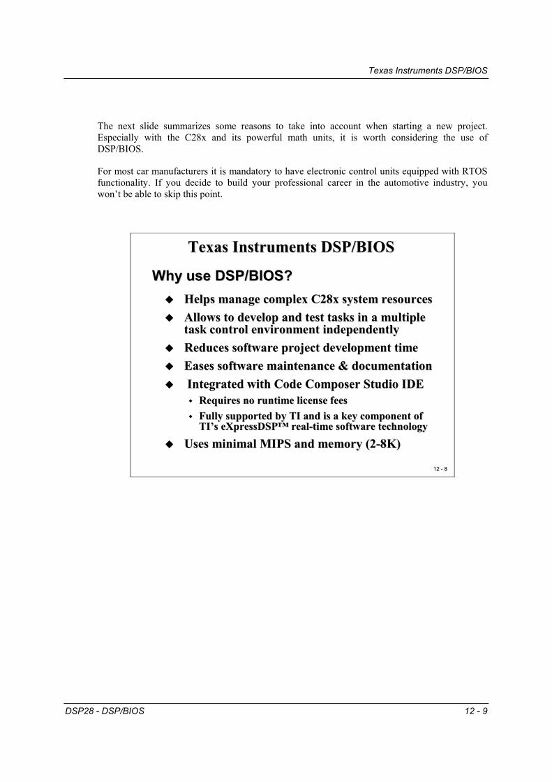
The next slide summarizes some reasons to take into account when starting a new project. Especially with the C28x and its powerful math units, it is worth considering the use of DSP/BIOS.
For most car manufacturers it is mandatory to have electronic control units equipped with RTOS functionality. If you decide to build your professional career in the automotive industry, you won’t be able to skip this point.
Helps manage complex C28x system resourcesHelps manage complex C28x system resourcesAllows to develop and test tasks in a multiple Allows to develop and test tasks in a multiple task control environment independentlytask control environment independentlyReduces software project development timeReduces software project development timeEases software maintenance & documentationEases software maintenance & documentationIntegrated with Code Composer Studio IDEIntegrated with Code Composer Studio IDE
Requires no runtime license feesRequires no runtime license feesFully supported by TI and is a key component of Fully supported by TI and is a key component of TI’sTI’s eXpressDSPeXpressDSP™ real™ real--time software technologytime software technology
Uses minimal MIPS and memory (2Uses minimal MIPS and memory (2--8K)8K)
Why use DSP/BIOS?Why use DSP/BIOS?
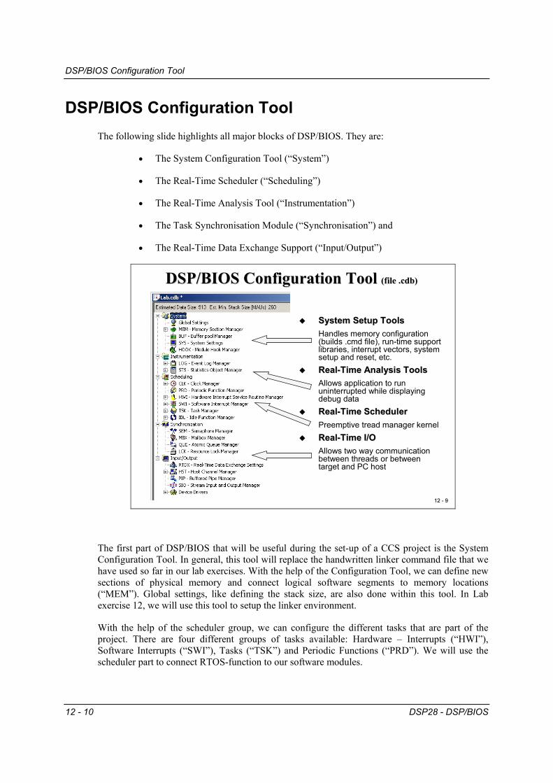
DSP/BIOS Configuration Tool
12 - 10 DSP28 - DSP/BIOS
DSP/BIOS Configuration Tool The following slide highlights all major blocks of DSP/BIOS. They are:
• The System Configuration Tool (“System”)
• The Real-Time Scheduler (“Scheduling”)
• The Real-Time Analysis Tool (“Instrumentation”)
• The Task Synchronisation Module (“Synchronisation”) and
• The Real-Time Data Exchange Support (“Input/Output”)
System Setup ToolsSystem Setup ToolsHandles memory configuration (builds .cmd file), run-time support libraries, interrupt vectors, system setup and reset, etc.RealReal--Time Analysis ToolsTime Analysis ToolsAllows application to run uninterrupted while displaying debug dataRealReal--Time SchedulerTime SchedulerPreemptive tread manager kernelRealReal--Time I/OTime I/OAllows two way communication between threads or between target and PC host
The first part of DSP/BIOS that will be useful during the set-up of a CCS project is the System Configuration Tool. In general, this tool will replace the handwritten linker command file that we have used so far in our lab exercises. With the help of the Configuration Tool, we can define new sections of physical memory and connect logical software segments to memory locations (“MEM”). Global settings, like defining the stack size, are also done within this tool. In Lab exercise 12, we will use this tool to setup the linker environment.
With the help of the scheduler group, we can configure the different tasks that are part of the project. There are four different groups of tasks available: Hardware – Interrupts (“HWI”), Software Interrupts (“SWI”), Tasks (“TSK”) and Periodic Functions (“PRD”). We will use the scheduler part to connect RTOS-function to our software modules.
DSP/BIOS Task Groups
DSP28 - DSP/BIOS 12 - 11
DSP/BIOS Task Groups If we look into a typical development cycle of a project that is not driven by an OS, we will face the following design problem:
12 12 -- 1010
TI DSP
Design Problem: Add a new FunctionDesign Problem: Add a new Function
Existing Function
New FunctionIssues:
Do we have enough remaining computing power to add another function?Are there possible resource conflicts between the new function and the existing system?Will the new system meet all time restrictions in a real-time embedded control system?
What are some possible solutions?
Function 1
Function 2
A new function is to be added to our existing project. A professional embedded system designer would NOT start immediately with the new coding and hope that afterwards everything will work as expected. That would be the ‘trial and error’ method and is no good at all for safety critical applications. Instead, a serious developer would try to answer the following questions first:
• How much computing power is still available BEFORE we add a new function?
• How much storage capacity will the new function need? Is there enough code memory left?
• What type of resources will be needed by the new function? Are there potential conflicts with other functions in the system?
• Are there any interactions, synchronisations or message transfers between the new function and the existing functions needed?
• What is the deadline of the new function, once it is called? What is the estimated computing time for the new function?
• Do I have to prioritize the new function against others? Are there consequences for the execution of other functions, when I have to modify the priorities of existing functions?
DSP/BIOS Task Groups
12 - 12 DSP28 - DSP/BIOS
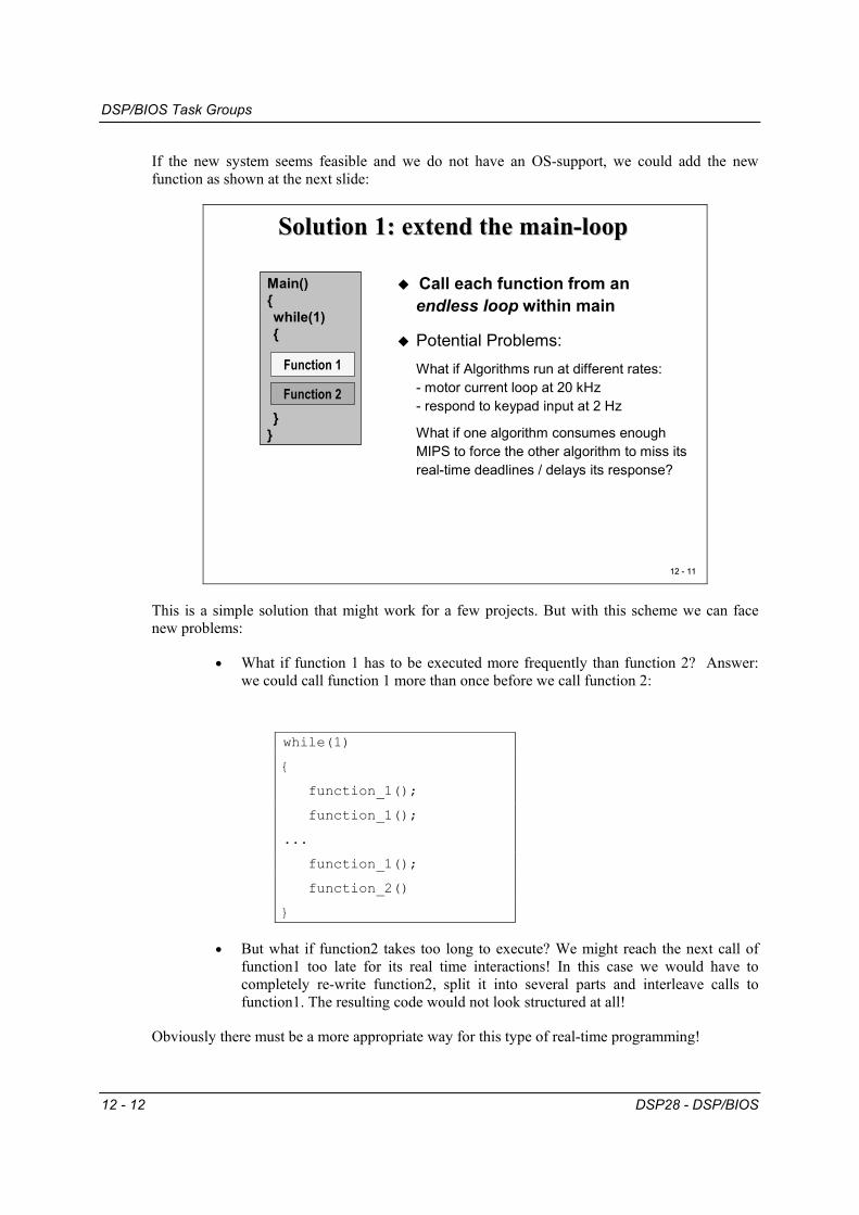
If the new system seems feasible and we do not have an OS-support, we could add the new function as shown at the next slide:
12 12 -- 1111
Solution 1: extend the mainSolution 1: extend the main--looploop
Function 2
Function 1
Main(){while(1){
}}
Potential Problems:What if Algorithms run at different rates:- motor current loop at 20 kHz- respond to keypad input at 2 Hz
What if one algorithm consumes enough MIPS to force the other algorithm to miss its real-time deadlines / delays its response?
Call each function from anendless loop within main
This is a simple solution that might work for a few projects. But with this scheme we can face new problems:
• What if function 1 has to be executed more frequently than function 2? Answer: we could call function 1 more than once before we call function 2:
while(1)
{
function_1();
function_1();
...
function_1();
function_2()
}
• But what if function2 takes too long to execute? We might reach the next call of function1 too late for its real time interactions! In this case we would have to completely re-write function2, split it into several parts and interleave calls to function1. The resulting code would not look structured at all!
Obviously there must be a more appropriate way for this type of real-time programming!
DSP/BIOS Task Groups
DSP28 - DSP/BIOS 12 - 13
If you already have some basic experience with microprocessors, you may have suggested using interrupts instead of the function loop in solution1. This principle is shown with the next slide:
12 12 -- 1212
Solution 2: use interruptsSolution 2: use interrupts
TI DSP
main{while(1);
}
Function1_ISR{
}
Function2_ISR{
}
Only one ISR can run at a time: Function 1 will be delayed, eventually missing its deadline…
Period Compute CPU Usage
Function 1: 0.05 ms 1 µs 2%Function 2: 500 ms 3 µs ~ 0%
2%
Function 2
Function 1
An interrupt driven system places each function in its own ISR
running
idle
Time 1 2 3 54 6 70
Function 1
Function 2
We distribute all functions into dedicated Interrupt Service Routines (ISR). The main function will perform basic initialization routines for the project like system setup, memory initialization, peripheral unit setups, enabling of desired interrupts, prepare timer periods etc. At the end of main the code will stay in an idle-loop, in C usually coded as “while(1);” or “for( ; ; );”. When one of the hardware units, for example a timer, calls its ISR, the assigned function will be executed. After finishing this ISR the processor will return to main’s idle-loop and await the next interrupt.
Our previous example could use a first timer that is initialized to a period of 50µs and a second timer with a period of 0.5s. All we would have to do is to connect timer 1 interrupt service to function 1 and timer 2 to function 2.
This principle will work fine for most of the time, but sometimes our control unit will behave unexpectedly. Why is this?
If the processor executes function 2 and at the same time function 1 is requested by timer 1 ISR, the processor will finish function 2 first before it deals with the next request. In this case the execution of function 1 will be delayed. In best cases our system will behave a little bit sluggishly, in worst cases the motor that is controlled by function 1 will change from full forward to full reverse….
DSP/BIOS Task Groups
12 - 14 DSP28 - DSP/BIOS
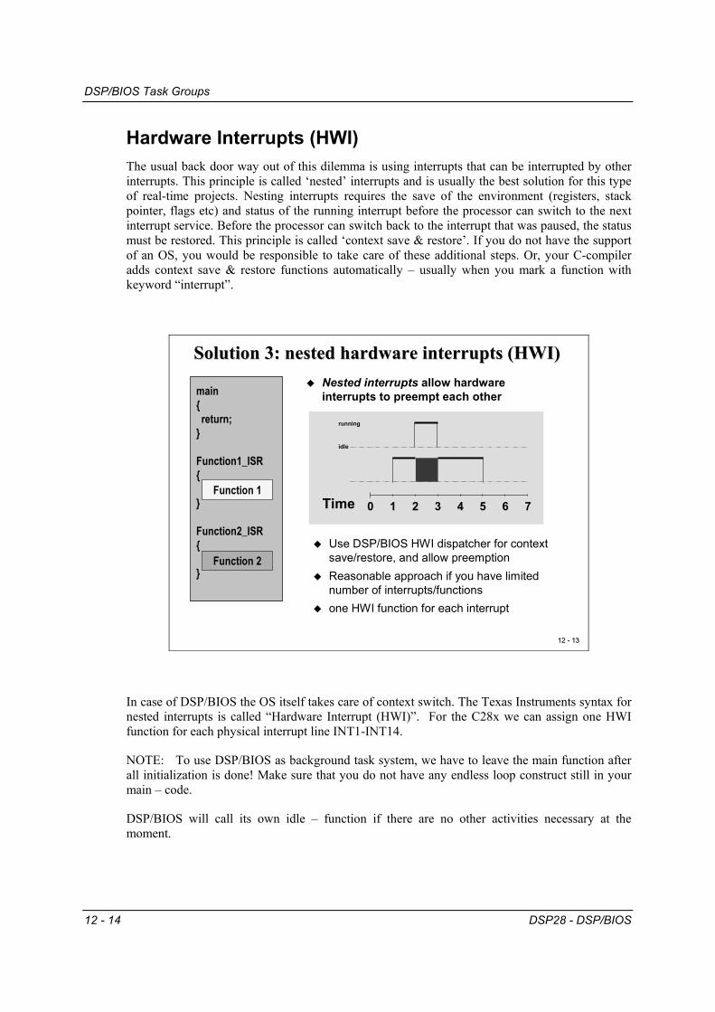
Hardware Interrupts (HWI) The usual back door way out of this dilemma is using interrupts that can be interrupted by other interrupts. This principle is called ‘nested’ interrupts and is usually the best solution for this type of real-time projects. Nesting interrupts requires the save of the environment (registers, stack pointer, flags etc) and status of the running interrupt before the processor can switch to the next interrupt service. Before the processor can switch back to the interrupt that was paused, the status must be restored. This principle is called ‘context save & restore’. If you do not have the support of an OS, you would be responsible to take care of these additional steps. Or, your C-compiler adds context save & restore functions automatically – usually when you mark a function with keyword “interrupt”.
Use DSP/BIOS HWI dispatcher for context save/restore, and allow preemptionReasonable approach if you have limited number of interrupts/functionsone HWI function for each interrupt
running
idle
Time 1 2 3 54 6 70
Nested interrupts allow hardwareinterrupts to preempt each othermain
{return;
}
Function1_ISR{
}
Function2_ISR{
}Function 2
Function 1
In case of DSP/BIOS the OS itself takes care of context switch. The Texas Instruments syntax for nested interrupts is called “Hardware Interrupt (HWI)”. For the C28x we can assign one HWI function for each physical interrupt line INT1-INT14.
NOTE: To use DSP/BIOS as background task system, we have to leave the main function after all initialization is done! Make sure that you do not have any endless loop construct still in your main – code.
DSP/BIOS will call its own idle – function if there are no other activities necessary at the moment.
DSP/BIOS Task Groups
DSP28 - DSP/BIOS 12 - 15
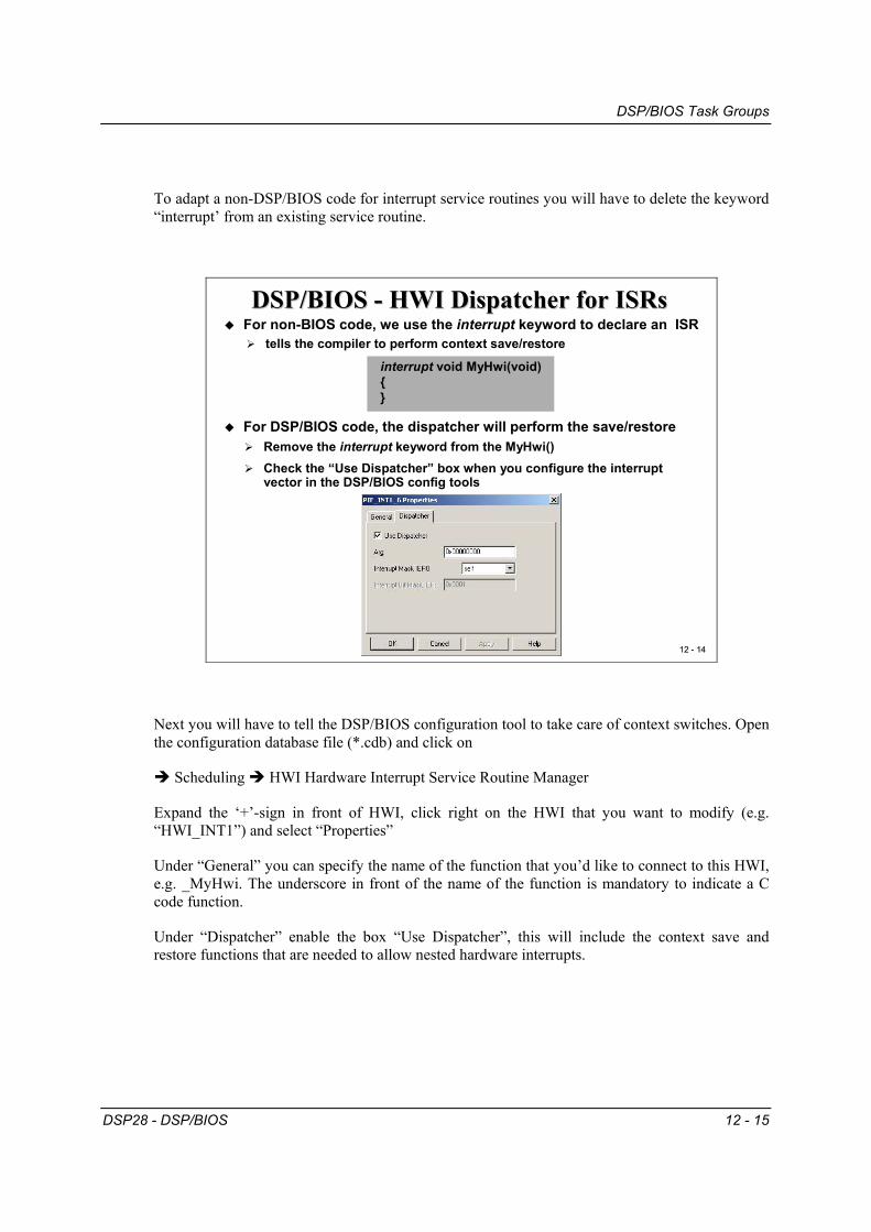
To adapt a non-DSP/BIOS code for interrupt service routines you will have to delete the keyword “interrupt’ from an existing service routine.
12 12 -- 1414
interrupt void MyHwi(void){}
DSP/BIOS DSP/BIOS -- HWI Dispatcher for HWI Dispatcher for ISRsISRsFor non-BIOS code, we use the interrupt keyword to declare an ISR
tells the compiler to perform context save/restore
For DSP/BIOS code, the dispatcher will perform the save/restoreRemove the interrupt keyword from the MyHwi()Check the “Use Dispatcher” box when you configure the interrupt vector in the DSP/BIOS config tools
Next you will have to tell the DSP/BIOS configuration tool to take care of context switches. Open the configuration database file (*.cdb) and click on
Scheduling HWI Hardware Interrupt Service Routine Manager
Expand the ‘+’-sign in front of HWI, click right on the HWI that you want to modify (e.g. “HWI_INT1”) and select “Properties”
Under “General” you can specify the name of the function that you’d like to connect to this HWI, e.g. _MyHwi. The underscore in front of the name of the function is mandatory to indicate a C code function.
Under “Dispatcher” enable the box “Use Dispatcher”, this will include the context save and restore functions that are needed to allow nested hardware interrupts.
DSP/BIOS Task Groups
12 - 16 DSP28 - DSP/BIOS
Software Interrupts (SWI) The next group of DSP/BIOS functions is called “Software Interrupts (SWI)”. As the name says, this group of functions is initiated by software requests. The difference to HWI’s is that the user has more flexibility in the system design when using software interrupts. Whilst the priority of all hardware interrupts is given by the C28x and can’t be changed at all, the user has full flexibility to assign priorities to software interrupts as static or dynamic priorities. The number of software interrupts is not limited by DSP/BIOS; of course the number of feasible software interrupts depends on the computing time that is consumed by all software interrupt functions.
Make each algorithm an independentsoftware interruptSWI scheduling is handled by DSP/BIOS
HWI function triggered by hardwareSWI function triggered by softwaree.g. a call to SWI_post()
Why use a SWI?No limitation on number of SWIs, and priorities for SWIs are user-definedSWI can be scheduled by hardware or software event(s)Relocate task processing from HWI to SWI
Function 2
Function 1
A recommended principle is to limit the length of hardware interrupt service routines to an absolute minimum, just what is necessary to deal with the hardware event. All other activities that must be executed due to the hardware event are relocated into software interrupt services. The HWI schedules all actions that should follow the hardware event. Thus the DSP/BIOS controlled project is most flexible.
DSP/BIOS Task Groups
DSP28 - DSP/BIOS 12 - 17
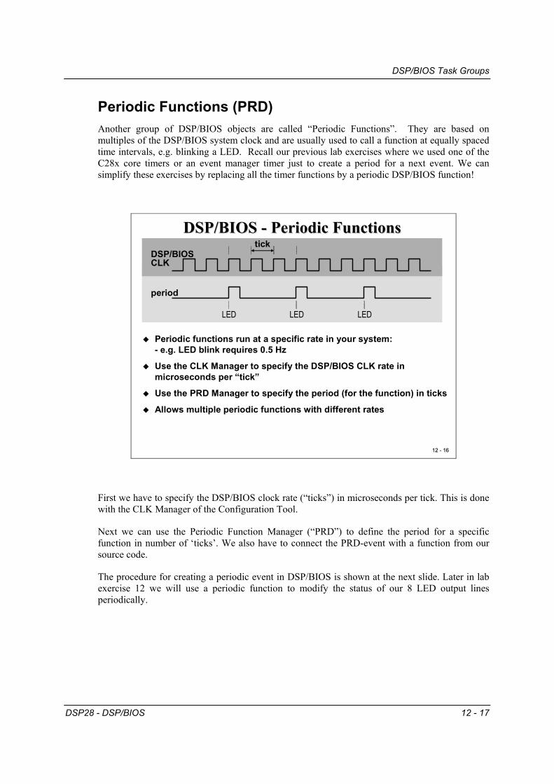
Periodic Functions (PRD) Another group of DSP/BIOS objects are called “Periodic Functions”. They are based on multiples of the DSP/BIOS system clock and are usually used to call a function at equally spaced time intervals, e.g. blinking a LED. Recall our previous lab exercises where we used one of the C28x core timers or an event manager timer just to create a period for a next event. We can simplify these exercises by replacing all the timer functions by a periodic DSP/BIOS function!
Periodic functions run at a specific rate in your system:- e.g. LED blink requires 0.5 Hz
Use the CLK Manager to specify the DSP/BIOS CLK rate in microseconds per “tick”
Use the PRD Manager to specify the period (for the function) in ticks
Allows multiple periodic functions with different rates
DSP/BIOSCLK
tick
First we have to specify the DSP/BIOS clock rate (“ticks”) in microseconds per tick. This is done with the CLK Manager of the Configuration Tool.
Next we can use the Periodic Function Manager (“PRD”) to define the period for a specific function in number of ‘ticks’. We also have to connect the PRD-event with a function from our source code.
The procedure for creating a periodic event in DSP/BIOS is shown at the next slide. Later in lab exercise 12 we will use a periodic function to modify the status of our 8 LED output lines periodically.
DSP/BIOS Task Groups
12 - 18 DSP28 - DSP/BIOS
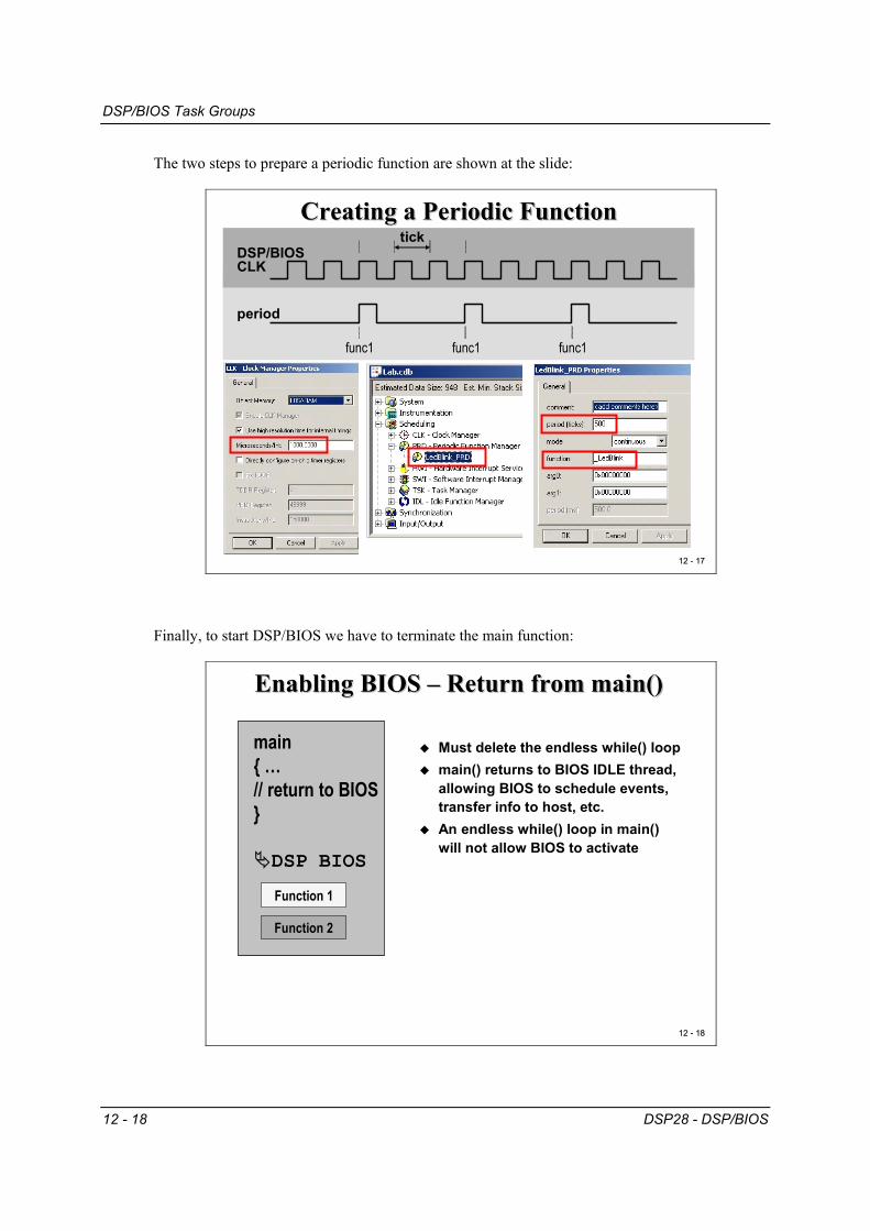
The two steps to prepare a periodic function are shown at the slide:
12 12 -- 1717
Creating a Periodic FunctionCreating a Periodic Function
period
func1 func1 func1
DSP/BIOSCLK
tick
Finally, to start DSP/BIOS we have to terminate the main function:
12 12 -- 1818
Enabling BIOS Enabling BIOS –– Return from main()Return from main()
main{ …// return to BIOS}
DSP BIOS
Function 2
Function 1
Must delete the endless while() loopmain() returns to BIOS IDLE thread,allowing BIOS to schedule events, transfer info to host, etc.An endless while() loop in main() will not allow BIOS to activate
Real-Time Analysis Tool
DSP28 - DSP/BIOS 12 - 19
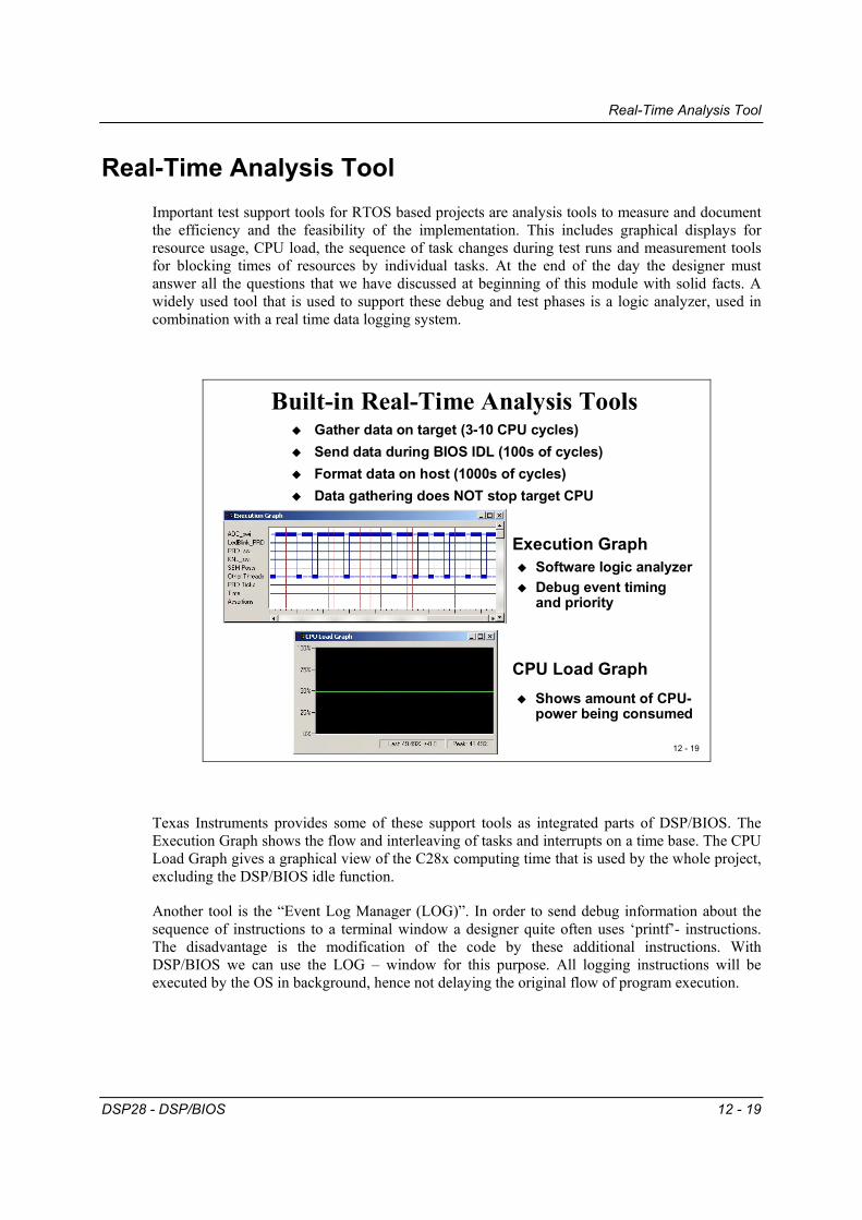
Real-Time Analysis Tool Important test support tools for RTOS based projects are analysis tools to measure and document the efficiency and the feasibility of the implementation. This includes graphical displays for resource usage, CPU load, the sequence of task changes during test runs and measurement tools for blocking times of resources by individual tasks. At the end of the day the designer must answer all the questions that we have discussed at beginning of this module with solid facts. A widely used tool that is used to support these debug and test phases is a logic analyzer, used in combination with a real time data logging system.
12 - 19
Built-in Real-Time Analysis ToolsGather data on target (3-10 CPU cycles)Send data during BIOS IDL (100s of cycles)Format data on host (1000s of cycles)Data gathering does NOT stop target CPU
Texas Instruments provides some of these support tools as integrated parts of DSP/BIOS. The Execution Graph shows the flow and interleaving of tasks and interrupts on a time base. The CPU Load Graph gives a graphical view of the C28x computing time that is used by the whole project, excluding the DSP/BIOS idle function.
Another tool is the “Event Log Manager (LOG)”. In order to send debug information about the sequence of instructions to a terminal window a designer quite often uses ‘printf’- instructions. The disadvantage is the modification of the code by these additional instructions. With DSP/BIOS we can use the LOG – window for this purpose. All logging instructions will be executed by the OS in background, hence not delaying the original flow of program execution.
DSP/BIOS API
12 - 20 DSP28 - DSP/BIOS
DSP/BIOS API The next slide is a summary of all API Modules that are part of DSP/BIOS. In the next lab exercise we will use the Memory Manager (MEM), System Clock Manager (CLK) and Periodic Function Manager (PRD).
12 12 -- 2020
DSP/BIOS DSP/BIOS -- API ModulesAPI Modules
Instrumentation/RealInstrumentation/Real--Time Analysis Time Analysis
LOGLOG Message log managerMessage log managerSTSSTS Statistics accumulator manager Statistics accumulator manager TRCTRC Trace manager Trace manager RTDXRTDX RealReal--Time Data Time Data eXchangeeXchange manager manager
Thread Types Thread Types
HWIHWI Hardware interrupt manager Hardware interrupt manager SWISWI Software interrupt manager Software interrupt manager TSKTSK MultiMulti--tasking manager tasking manager IDLIDL Idle function & process loop manager Idle function & process loop manager
Clock and Periodic Functions Clock and Periodic Functions
CLKCLK System clock manager System clock manager PRDPRD Periodic function manager Periodic function manager
Memory and LowMemory and Low--Level PrimitivesLevel Primitives
MEMMEM Memory manager Memory manager SYSSYS System services manager System services manager QUEQUE Queue manager Queue manager ATMATM Atomic functions Atomic functions GBLGBL Global setting manager Global setting manager
Lab Exercise 12
DSP28 - DSP/BIOS 12 - 21
Lab Exercise 12
12 12 -- 2121
Lab 12: Modify Lab Lab 12: Modify Lab 22 to use BIOSto use BIOS
Use your solution for Lab2 to begin with Modify the project to use DSP/BIOS functionality Let DSP/BIOS create the necessary Linker Command Files Replace the software delay loop from Lab2 by a periodic function (“PRD”) of DSP/BIOSCreate a new function “led_runner()” that will activate the next state of the LED-lineCall this function every 500ms with a PRD-function out of DSP/BIOS
For a detailed procedure see textbook!
Objective
The objective of this laboratory exercise is to implement the code from Lab2, this time using DSP/BIOS periodic functions rather than a simple software delay loop to generate the time separation.
Instead of using the linker command file from Lab2 we will use the DSP/BIOS Configuration Tool to auto generate the linker information
We will add a periodic function (PRD) to the DSP/BIOS system that will be used to execute the next state of our control sequence.
Procedure
Open Files, Create Project File 1. Create a new project, called Lab12.pjt in E:\C281x\Labs.
2. Open the file Lab2.c from E:\C281x\Labs\Lab2 and save it as Lab12.c in E:\C281x\Labs\Lab12.
Lab Exercise 12
12 - 22 DSP28 - DSP/BIOS
3. Add the source code file to your project: • Lab12.c
4. From C:\tidcs\c28\dsp281x\v100\DSP281x_headers\source add:
• DSP281x_GlobalVariableDefs.c
5. This is the first exercise in which we are using the DSP/BIOS. This requires a new linker command file to be added to our project. The new command-file, also provided by Texas Instruments with the peripheral header files, excludes the PieVectorTable structure from the project.
From C:\tidcs\c28\dsp281x\v100\DSP281x_headers\cmd add:
• F2812_Headers_BIOS.cmd
6. The DSP/BIOS itself will include the C environment library files into the project. There is no need to add the file “rts2800_ml.lib” manually.
7. Next we have to create a DSP/BIOS Configuration File (*.cdb). Select:
File New DSP/BIOS Configuration
From the next window select the template “c28xx.cdb” to begin with. Save the new configuration file as “lab12.cdb”.
8. Add the configuration file to your project:
Project Add Files to Project lab12.cdb
9. The DSP/BIOS configuration has automatically generated a new linker command file “lab12cfg.cmd”, which must be added to our project manually:
Project Add Files to Project lab12cfg.cmd
Project Build Options 10. Setup the search path to include the peripheral register header files. Click:
Project Build Options
Select the Compiler tab. In the preprocessor Category, find the Include Search Path (-i) box and enter:
NOTE: Do NOT setup the stack size inside the Build Options! It will be done with the help of the DSP/BIOS configuration tool later.
Modify Source Code 11. Open Lab12.c to edit.
Disable the Watchdog Timer:
In function “InitSystem” make sure to disable the watchdog timer (register WDCR). For the first DSP/BIOS – Test we would like to keep the code as simple as possible. Later, if the code works, we can easily expand our test setup.
Delete function “delay_loop”:
Recall, in lab2 we used a software delay function for the interval between the LED-output instructions. For lab12, all timing will be done by DSP/BIOS.
Delete the endless “while(1)” construct in “main”:
At the end of “main” DSP/BIOS will take care about the background activities and the timing of all active tasks. If we do not return from main, DSP/BIOS will not start.
Add a new function “led_runner()” at the end of your code:
This new function will be called by DSP/BIOS periodically. The code inside this function should copy the next value from array LED[8] to the LED-lines.
Remove variable “i” and “LED[8]” from “main” and add them at the beginning of this new function. Declare them as “static” and initialize “i” to 0.
Increment “i” with each call of function “led_runner” and load the next value out of “LED[8]” into register “GpioDataRegs.GPBDAT.all”.
Do not forget to reset i to 0 after the end of the sequence was reached!
Edit DSP/BIOS Configuration 12. Open File “lab12.cdb”.
“MEM – Memory Section Manager”
Inspect the “System” Category by expanding the ‘+’ sign in front. Click right on “MEM – Memory Section Manager” and select “Properties”. Verify that in the “General”- Folder the Stack Size has already been defined as 0x0200. This is a default value for the stack size that was initialized when we created the configuration file. If necessary for larger project, this size can be adjusted here. For now, just keep the default value.
Lab Exercise 12
12 - 24 DSP28 - DSP/BIOS
Next, move to the “Compiler Sections” tab. This table controls the connection of code sections to physical memory in an identical way, to which we used in our handmade linker command files. When we edit the configuration, this table will be used by CCS to auto-generate the linker command file “lab12cfg.cmd”, which is already part of our project. For now, just keep the table with its default values.
Close the “MEM” – menu by clicking <OK>.
“CLK” – Clock Manager
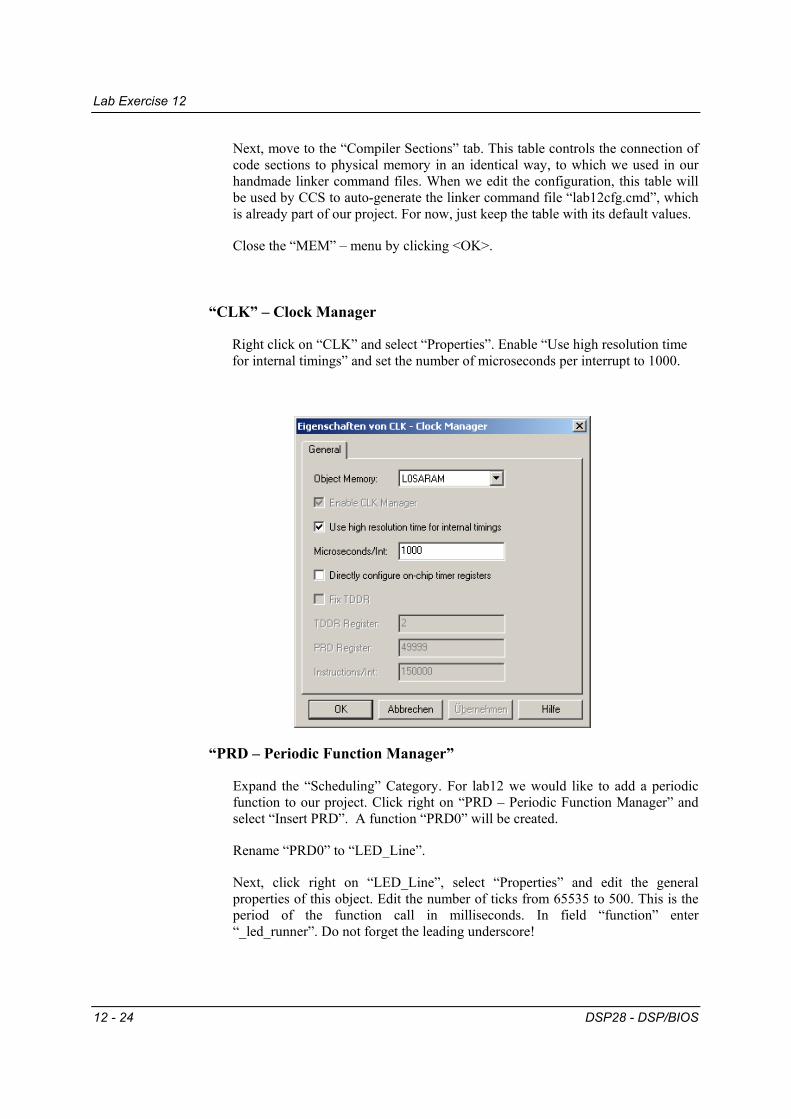
Right click on “CLK” and select “Properties”. Enable “Use high resolution time for internal timings” and set the number of microseconds per interrupt to 1000.
“PRD – Periodic Function Manager”
Expand the “Scheduling” Category. For lab12 we would like to add a periodic function to our project. Click right on “PRD – Periodic Function Manager” and select “Insert PRD”. A function “PRD0” will be created.
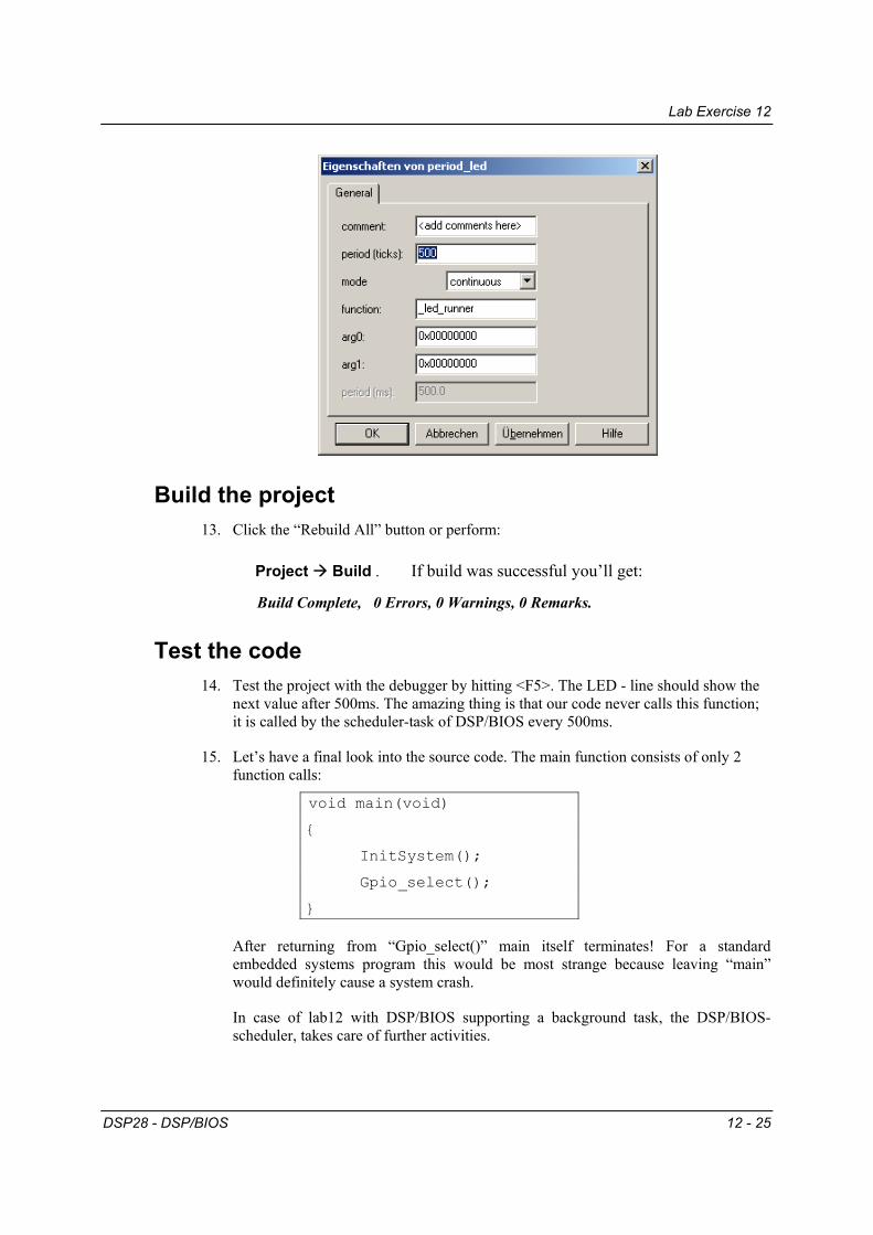
Rename “PRD0” to “LED_Line”.
Next, click right on “LED_Line”, select “Properties” and edit the general properties of this object. Edit the number of ticks from 65535 to 500. This is the period of the function call in milliseconds. In field “function” enter “_led_runner”. Do not forget the leading underscore!
Lab Exercise 12
DSP28 - DSP/BIOS 12 - 25
Build the project 13. Click the “Rebuild All” button or perform:
Project Build . If build was successful you’ll get:
Build Complete, 0 Errors, 0 Warnings, 0 Remarks.
Test the code 14. Test the project with the debugger by hitting <F5>. The LED - line should show the
next value after 500ms. The amazing thing is that our code never calls this function; it is called by the scheduler-task of DSP/BIOS every 500ms.
15. Let’s have a final look into the source code. The main function consists of only 2 function calls:
void main(void)
{
InitSystem();
Gpio_select();
}
After returning from “Gpio_select()” main itself terminates! For a standard embedded systems program this would be most strange because leaving “main” would definitely cause a system crash.
In case of lab12 with DSP/BIOS supporting a background task, the DSP/BIOS-scheduler, takes care of further activities.
Lab Exercise 12
12 - 26 DSP28 - DSP/BIOS
16. You can experiment with different time intervals for the call of function “led_runner” by changing the period property of PRD-function “LED_Line” in the DSP/BIOS configuration file “Lab12.cdb”.
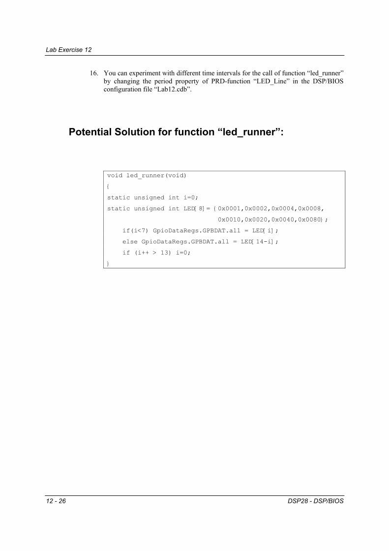
Potential Solution for function “led_runner”:
void led_runner(void)
{
static unsigned int i=0;
static unsigned int LED[8]= {0x0001,0x0002,0x0004,0x0008,