UNCLASSIFIED AD NUMBER CLASSIFICATION CHANGES TO: FROM: LIMITATION CHANGES TO: FROM: AUTHORITY THIS PAGE IS UNCLASSIFIED AD045708 unclassified confidential Approved for public release; distribution is unlimited. Distribution authorized to U.S. Gov't. agencies and their contractors; Administrative/Operational Use; JAN 1953. Other requests shall be referred to Air Force Wright Air Development Center, Aeropropulsion Laboratory, Wright-Patterson AFB, OH 45433. 20 may 1954, per document marking; afapl ltr, 7 jun 1972
Transcript
UNCLASSIFIED
AD NUMBER
CLASSIFICATION CHANGESTO:FROM:
LIMITATION CHANGESTO:
FROM:
AUTHORITY
THIS PAGE IS UNCLASSIFIED
AD045708
unclassified
confidential
Approved for public release; distribution isunlimited.
Distribution authorized to U.S. Gov't. agenciesand their contractors;Administrative/Operational Use; JAN 1953. Otherrequests shall be referred to Air Force WrightAir Development Center, AeropropulsionLaboratory, Wright-Patterson AFB, OH 45433.
20 may 1954, per document marking; afapl ltr, 7jun 1972
UNCLASSIFIED
AD NUMBER
CLASSIFICATION CHANGESTO:
FROM:
AUTHORITY
THIS PAGE IS UNCLASSIFIED
AD045708
confidential
restricted
22 mar 1954, per document marking
UNCLASSIFIED
AD NUMBER
CLASSIFICATION CHANGESTO:FROM:
LIMITATION CHANGESTO:
FROM:
AUTHORITY
THIS PAGE IS UNCLASSIFIED
AD045708
unclassified
confidential
Approved for public release; distribution isunlimited.
Distribution authorized to U.S. Gov't. agenciesand their contractors;Administrative/Operational Use; JAN 1953. Otherrequests shall be referred to Air Force WrightAir Development Center, Attn: Aero PulpulsionLaboratory, Wright-Patterson AFB, OH 45433.
20 may 1954, per document marking; afapl ltr, 7jun 1972
BeesiUfeH c.f cur limited s^pplj, you are requested to retura this copy WHEN IT HAS SERVED YOUH PURPOSE so thai it may be made available to other requesters. Your cooperation will be appreciated.
•S3
€l
NOTICE: WHEN GOVERNMENT OR OTHER DRAWINGS, SPECIFICATIONS OR OTHER DATA ~AHE~USED FOR ANY PURPOSE OTHER THAN IN CONNECTION WITH A DEFINITELY RELATED GOVERNMENT PROCUREMENT OPERATION, THE U. S. GOVERNMENT THEREBY INCURS NO RESPONSIBILITY, NOR ANY OBLIGATION WHATSOEVER; AND THE FACT THAT THE GOVERNMENT MAY HAVE FORMULATED, FURNISHED, OR IN ANY WAY SUPPLIED THE SAID DRAWINGS, SPECIFICATIONS, OR OTHER DATA S3 NOT TO HE REGARDED BY IMPLICATION OR OFHSRWISE AS IN ANY MANNER LICENSING THE HOLDER OR ANY OTHER PERSON OR CORPORATION, OR CONVEYING ANY RIGHTS OR .PERMISSION TO MANUFACTURE, USE OR SELL ANY PATENTED INVENTION THATTflAY IN ANY WAY BE RELATED THERETO.
Octave Band analyses of the noise spectra of Pulse- Jet engines have been made for the following purposes;
1. Engine sixes from ~i! to 12.5" i?1- diameter have been studied to determine the influence of engine size and rate of fuel flow upon the nois-i; spectrum, operating frequency and thrust.
2, Hoise Control configurations have been tested, including twin engines in parallel configuration with an acoustically treated cowl around the tailpipes, twin engines in opposed configuration, a single engine with an integral acoustic filter, and two typos of s e r r a tea tailpi pe*
The present data indicates that power input (engine size and rate of fuel flow), is not the controlling factor in noise output. There is a strong indication that the high frequency portion of the noise spectrum is controlled largely by the velocity o: jases issuing from th •<n ,i>. i.fj%
This report describes work accomplished on item 1.5 of Sii.htb.it A, Supplementary Agreement No, 5 of Contract AF'33 (600)-5360 during the month of February, 195*+*
This is the fifth report to be submitted describ- ing the development of noise control and the use of the Pulse-Jet Analog. The report is submitted by the American Helicopter Co., Inc., describing the study program being conducted by Paul S, Veneklasen, Consultant in Acoustics,
The work was carried out and is reported by Paul S. Veneklasen and staff members G. P. Brocket* and M3 Herwick
Heretofore when it has been necessary to sake calculations of. expected noise from Pulse-Jet engines, wa have been obliged to extrapolate data fs'oiu vary limited experience with various sizes of engines. It has been assumed that noise output would be proportional to rate of fuel flow, that is, to power input. The following study shows that
••' '*'WS
.news*'*""
wgt/cjrff Asiisaptgr e-s. inc. ?Afc
this assumption is far from true and demonstrates clearly certain other factors which are apparently of much greater importance in noise prodiiction by Jet propulsion devices. All. measurements of noise spectra here reported were made at a distance of three feet fron the center line of th« engines on a perpendicular aidvay along their length, except. for the 12,5" engine.
%2,?. The 6.75" Standard Single Shell Knrine
Most of our earlier studies in con- nection with the noise control program nave usea a single shell 6.75" engine, which has a tube length of 3** Inches, It is only in deference to this previous work that we refer to this as a "standard" engine. The noise output spectrum of this engine is shown in Figure for several different fuel flow condi' tions It rfill be notea that fo "f ft :ne lowest rate of fuel flow the noise spectrum is consid- erably reduced, whereas for higher valuer, of fuel flow over a considerable range there is very little change in spectrum leve]
3j>g»3.$h« 6J7J5LW.JJLM&g^gftaH Srato y&th,
Thie engine is identical with the standard engine except for the tailpipe which
length to M+ inches. Figure 3 shows noise spectra for three different fuel flow rates. Values of thrust and operating frequency for various fuel flows are given with each figure,
This engine is like the previous one except for &n additional conical shell which is shown in Figure {?. Pigu.c 6 ohv/ws the
i^^a^HfeOf-swttB.*.
:'^^m^,^^s «-—- ,._,.>
PAGt 0,
noise spectra for this engine.
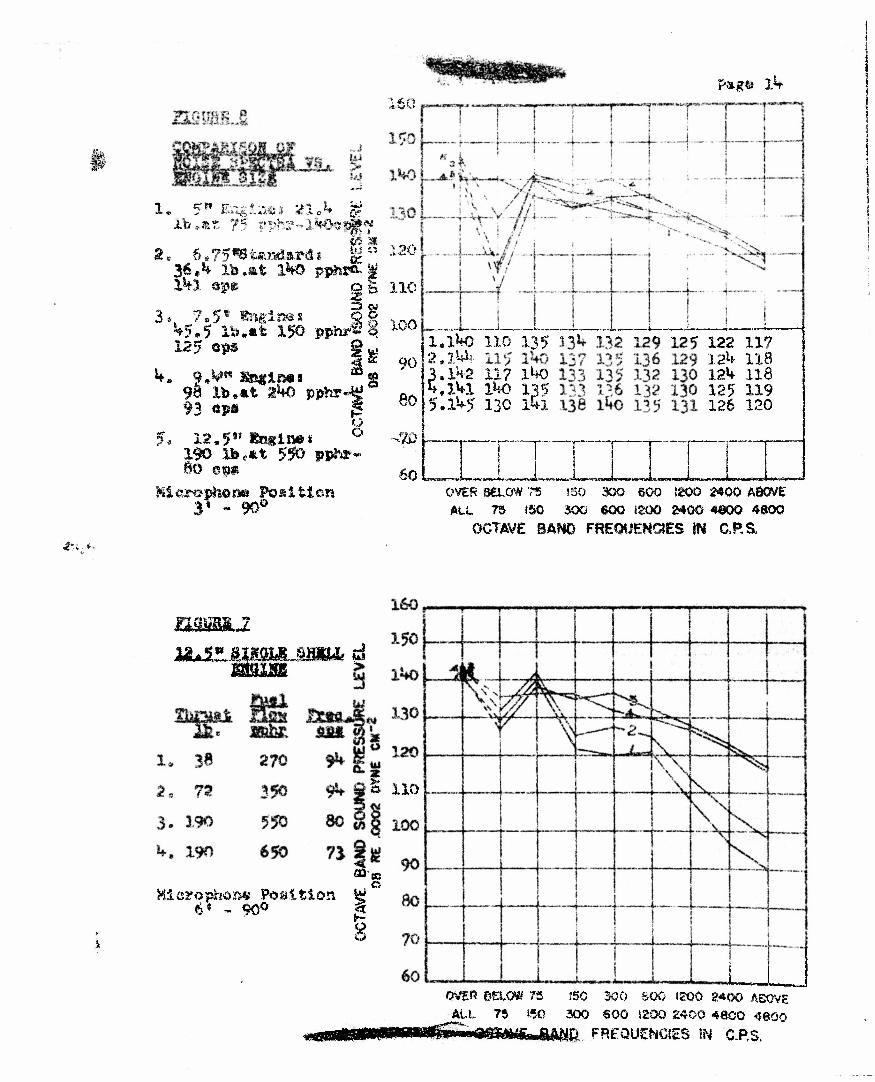
^.2.5 The. 12.5" Single Shell Engine
Figure ? shows nctse spectra for four different fuel flows. This data shows the largest variation in high frequency noise iporttrum. as a function of fuel flow, which
1 »rS fen
how small na.s yet boen rcunci ror a riuse-Jet engine
the variation Note in contrast in the lower tanas. It is also interesting to note the extreme variation in operating frequency which accompanies changes in fuel flow in this engine. This is one reason for the peculiar behavior of the noise spectra in the first two low frequency bands, be^uac; the fundamental frequency actually moves from one band into another. It would be more illumin- ating 5 although It does not at the moment seem worthwhile, bo analyze these noise spectra in more detail so as to determine 'Che levels of the prominent harmonic compon- ents which constitute the low frequency port!or of a Pulse-Jet noise spectrum. It should be pointed cut tl;at this engine vss ^measured at a distance of six feet* In vis-* of the difficulties of starting this engine and the expectation of considerably higher levels tnan were actually produced, it was not considered saff> to .Leave the microphone in its usual fixed position^ therefore the microphone vas kept at a safe distance until the engine was operating stably, whereupon it was moved to the 65 position, Comparison of data from Report No. I63-K-I of Sept. 28, 1951 indicates that the spectrum may be expected to be approx- imately 3 db higher at the 3! position.
1,2^6,, .Comparison of Koiae, vs u Size
Noise spectra for each of the above engines for a typical medium fuel flow rate are combined in Figure 8. In this case the spectrum from the 12„5S! <?tigine is increased by 3 db for proper comparison; also the spectrum lor a 9A" engine is included, data being drawn from Report. No» 163-K-l. This data very clearly indicates that there is no suh*?tance to r.he
L.i..« !
•:',\t7»g; o
thesis that noise output Is proportional to power input» This finding suggests that one should search elsewhere for the controlling factor in noise production.
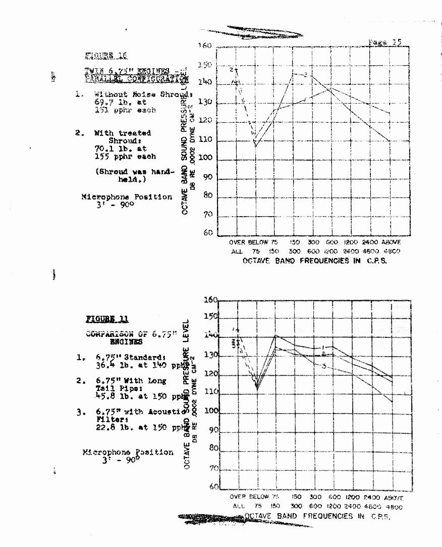
One of the attempts in the study of noise control possibilities is represented in Figures 9 and 10, which show a simple acoustic filter built on the tailpipe of a o.?'5" engine. This filter consists siiaply of an extra cylind- rical shell around the tailpipe. The cavity so formed is connected with the tailpipe through perforations. The performance of this device is indicated Ir, Figure 11. where its spectra is compared with more typical 6.75" engines.
The greatly reduced thrust produced by this engine is Indicative of lower average exhaust velocity since the effect of an acousti- cal filter is to convert a pulsating flow of gas into a steady flow. Unfortunately, this method of noise reduction is hardly tolerable. which emphasises the point that we are obliged co find methods of noise control which will not
.-.»>
S>A i~l
destroy the thrust-producing mechanism of the Pulse-Jet engine. The above result confirms some of our earlier approach. It appears that a proper method must retain the pulsating output flow from the tailpipe and surround this outflow, for noise reduction, at sufficient distance to avoid rearward reaction forces on the enclosing shroud
In this same "between two different most apparent. It 1; wis comparison that t greater thrust produce The possible explanati study is as follows: encloses a larger mass pipe probably produces ing a larger mass exhaust velocity.
Of R
f i gur tajIpi intere he eng s the" on whi the lo of ga 1 *-q t
e the comparison pe lengths is also sting to note in ine with the lower noise level. oh will bear further nger engine which ses in the ta.il- hrust by aceelerat- a lower value of
3.3.2 Twin 6.75.", Engines In Parallel Configura- tion
The following data continues tests of this configuration, to which considerable study has already been devoted. Figure 12 shows this configuration mounted on a test st and The present tescs were intended to study the effectiveness of a shroud having an acoustically absorbent lining, which is shown In Figure 13, Figures 14 and 15 show the enshrouded engine configuration mounted on the test stand. The lining of the shroud consists of Refrasil wool (nigh temperature Flberglas) which is held in place by a layer of Refrasil cloth and a perforated Inconel-X screen. It,was not expected that this parti- cular sample would be the last word in durabil- ity, not. to mention performance. However, the Refrasil liner did stay in place long enough to permit the recording of noise samples. The results are shown In Figure 16, which shows the spectrum for the twin engines without shroud, for comparison with the spectrum produced by the ermines in the treated shroud. The present tests confirm earlier experience with an untreated shroud, namely that the
$*65fc£StS»E»v~ ,„, .
^S%r«£s£;S*5
fyv&r ^»
benefit furnished b y he pairing of engines in the reduction of low frequency noise is to a large extent forfeited by the use of a shroud. However, the present tests also Indicate » useful reduction in high frequency spectrum, which has not been hitherto achieved. It is not at present known why the use of a shroud restores the low frequency noise. Perhaps the length of the shroud has been unfortunately chosen so that the resonant frequencies charact- erised by this length are excited by the engine. Since temperature conditions within this shroud are hardly predictihle, it is difficult to choose an appropriate length except on an empirical basis. However, if future work succeeds in achieving a combination of the low frequency noise reduction resulting from pairing, together with the high frequency reduction produced by a small treated shroud, we shall have achieved useful progress in noise control.
Figures 17 and 18 show the mounting on the test stand of the twin opposed configura- tion which has been tested previously. The present tests were intended to measure the performance of this configuration, using an acoustical liner for the common shroud, which diverts gases from the tailpipes, Figure 19 shuws the result, wh.».cn w«*s simply to strew the lining material over the neighborhood. The material did not stay In place long enough to measure its effectiveness. It had been planned to test this material, using small metal deflectors, to protect the material from direct impingement, but"these were not installed with the intention of determining the durability of the material. As a result the only noise records which are of value are shown in Figure 20, which is for the engine with common cowl but without lin^r,
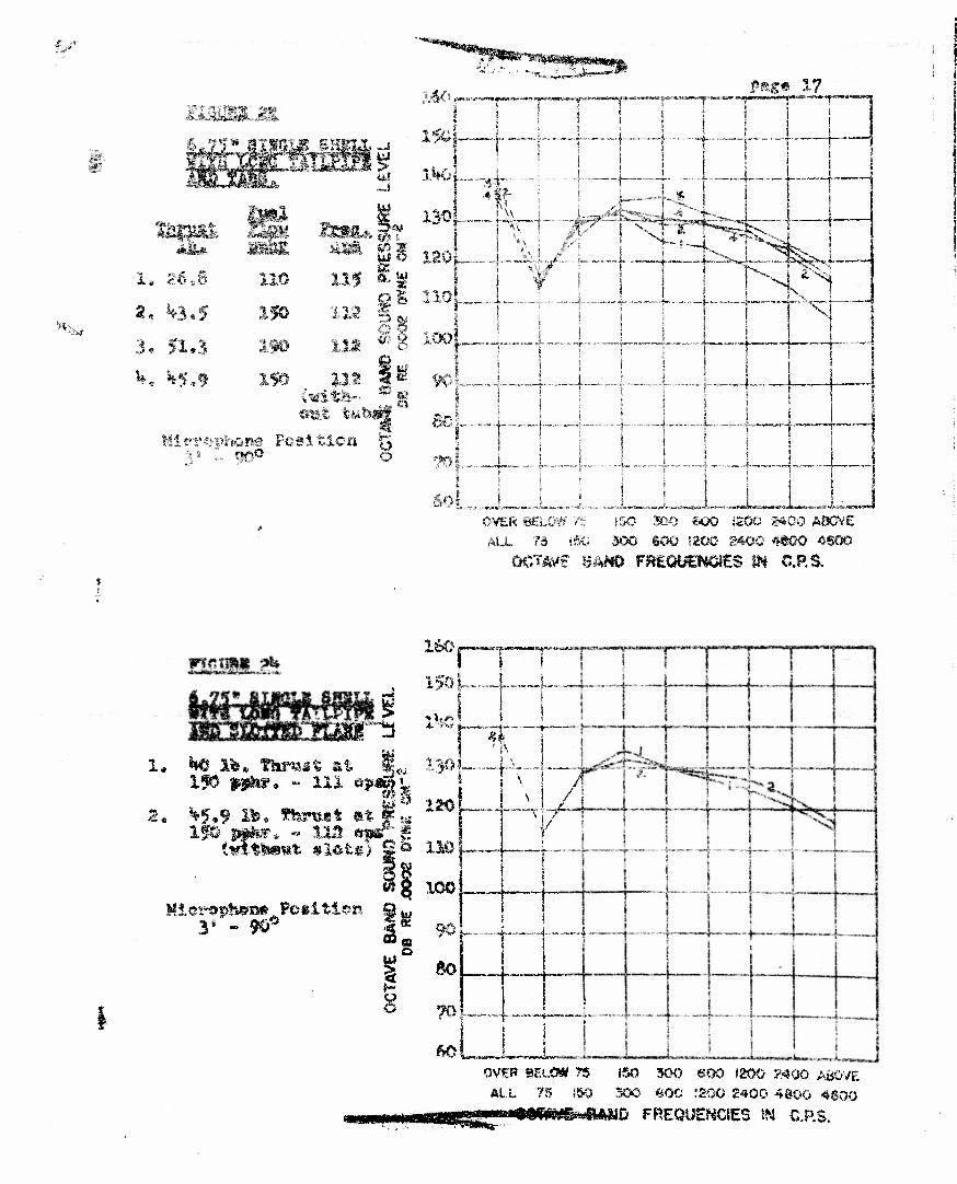
labs gxtendiry? trom_ Tal Ipj t.e
Rectangular extensions were welded to the tailpipe, as shown 1 ment was an attempt to 1 by the British, of serrating the tailpipe of a Jet engineB We do not know what theoret
n Figure 21. This expert* est the method proposed
e •t
'*«*••••*,.
•lLii«fcfc!
f,'j? /.<?r. ^. * i .• *•,:- *
(tfte* PAGf
background may exist for such a proposal. Figure 22 shows that the results were negative
TaiIpjpe
This experiment was a slightly different attempt to test the British theory. Hacksaw slots were cut into the trailing edge cf the tailpipe for about the length of the flared section, as shown in Figure 23. Figure Zh again indicates insignificant results,,
1335 h ,.~J
PAGE
KO CON C L U y K
A, Noise spectra have been measured for engines ranging in size from 55' diameter to 12.!>• diaxaeter. It 3s found that size alone is not the controlling factor in nojse output.
B, Each engine has been studied for the influence of rate of fuel flow on noise output. It is found that for very low rates of fuel flow, the high frequency portion of the spectrum is comparatively reduced,
C, Operating frequency has -also been studied as a function of rate of fuel flow. It is found .that in general the fundamental frequency decreases as
0.
H.
I.
the fuel flow is increased,
D. The influence of tube geometry is indicated by the fact that, for a given rate of fuel flow and chamber diameter, the high frequency noise is decreased and the thrust Is increased if a longer tailpipe with larger diameter is used,
E. There is a strong indication that a primary factor in determining high frequency noise spectrum is tho exit velocity oi the gases *
''ptro' ^•f •)-> ••» •
configuration, it is found that an acoustically treated cowl surrounding the tailpipes produces a useful amount of high frequency noise: reduction* Unfortunately, the advantage of low frequency noise cancellation is largely lost in the present configu- ration. The effect on thrust is not indicated because the cowl was hand-held.
The noise reduction for the twin engine opposed configuration with an acoustically-lined tailpipe duct could not be evaluated becatise the lining Material was blown out immediately upon starting.
A built-in acoustical filter reduced the high frequency noise with severe loss of thrust.
Two types of serrated edges at the tailpipe exhause proved ineffective.
forma*1 ^ Because of our limited supply, you are requested to return this copy WHEN IT HAS SERVED YOUR PURPG3E so that it may be made available to other requesters. Your cooperation will m appreciated.
^Vv.fW^:.-^'c;
*&i
NOTICE: WHEN GOVERNMENT OB OTHER DRAWXNGB, SPECIFICATIONS OB OTHER DATA AS&'tflffiD FOE ANY PURPOS*! OTHER TWAN ?w CONNECTION WTfH A DEFINITELY RELATED GOVERNMENT PROCUREMENT OPERATION, THE U. & GOVERNMENT THEREBY INCURS NO RESPONSIBILITY, NOR ANY OBLIGATION WHATSOEVER; .\*13 THE FACT TEAT THE GOVSEilMEKT MAY fiAv/v FOEMUuATSo. *T ^T^Ol.. > "a ^ ANY WAY VUPfLIKD TEE SAlU DRAWINGS, SPECIi?-i.wATS-:fiIS. G£ CTHEE DAT.?*. 2S ,-;OT TO B^ RE&AR1DED BY IMPLICATION OE OTHERWISE AS m ANY MAKSER LICENSING THE HOLDER OR ANY OTHER PERSON OR CORPORATION, OR COK^EYSHG A-.W. WWmS Ois.PisStMISSSON TO MAN1JFACTV?rO-;
USE OR SELL ANY PATENTED INVENTION TM^'MAY IN ANY fr'AY BiS RELATED THER^C,