TO APPEAR IN IEEE JOURNAL OF SOLID-STATE CIRCUITS 1 ASIC Implementation of Soft-Input Soft-Output MIMO Detection Using MMSE Parallel Interference Cancellation Christoph Studer, Member, IEEE, Schekeb Fateh, Student Member, IEEE, and Dominik Seethaler Abstract—Multiple-input multiple-output (MIMO) technology is the key to meet the demands for data rate and link reliability of modern wireless communication systems, such as IEEE 802.11n or 3GPP-LTE. The full potential of MIMO systems can, however, only be achieved by means iterative MIMO decoding relying on soft-input soft-output (SISO) data detection. In this paper, we describe the first ASIC implementation of a SISO detector for iterative MIMO decoding. To this end, we propose a low- complexity minimum mean-squared error (MMSE) based paral- lel interference cancellation algorithm, develop a suitable VLSI architecture, and present a corresponding four-stream 1.5mm 2 detector chip in 90 nm CMOS technology. The fabricated ASIC includes all necessary preprocessing circuitry and exceeds the 600 Mb/s peak data-rate of IEEE 802.11n. A comparison with state-of-the-art MIMO-detector implementations demonstrates the performance benefits of our ASIC prototype in practical system-scenarios. Index Terms—Very-large scale integration (VLSI), wireless communication, multiple-input multiple-output (MIMO), spatial multiplexing, iterative detection and decoding, soft-input soft- output (SISO), minimum mean-square error (MMSE), parallel interference cancellation (PIC). I. I NTRODUCTION T HE continuous increase in data rate and quality-of-service of modern wireless communication systems can only be met by novel technologies providing higher spectral efficiency and improved link reliability. Multiple-input multiple-output (MIMO) technology [2], which uses multiple antennas at both ends of the wireless link, in combination with spatial multiplexing and channel coding is believed to be the key to re- liable, high-speed, and bandwidth-efficient data transmission. Therefore, MIMO technology is incorporated in many modern wireless communication standards, such as IEEE 802.11n [3] or 3GPP-LTE [4]. In MIMO communication systems, data detection, i.e., the separation of the spatially-multiplexed data streams, and chan- nel decoding are typically among the main challenges in com- This paper was presented in part at the 36th European Solid-State Circuits Conference (ESSCIRC), Sevilla, Spain, Sept. 2010 [1]. C. Studer is with the Communication Technology Laboratory (CTL), ETH Zurich, 8092 Zurich, Switzerland, (e-mail: [email protected]). S. Fateh is with the Integrated Systems Laboratory (IIS), ETH Zurich, 8092 Zurich, Switzerland (e-mail: [email protected]). D. Seethaler was with the Communication Technology Laboratory (CTL), ETH Zurich, 8092 Zurich, Switzerland and is now with RobArt, 4020 Linz, Austria (e-mail: [email protected]). MATLAB code of a simulation environment for iterative MIMO decoding including the SISO MMSE-PIC algorithm is available for download at http://www.nari.ee.ethz.ch/commth/research/downloads/ putational complexity and power consumption. Therefore, cor- responding efficient implementations are the key to facilitate high-performance, low-power, and low-cost user equipment. The performance of MIMO technology critically depends on the employed data-detection algorithm and corresponding methods usually entail very high computational complexity. In particular, the computational complexity of the optimum MIMO detection algorithm scales exponentially in the number of spatial streams [2]. Hence, research has mainly focused on the development of low-complexity algorithms including their efficient implementation in hardware. For example, MIMO detection based on the sphere-decoding (SD) algorithm [5]– [7] is able to achieve close-to-optimal error-rate performance. However, corresponding implementations require multiple par- allel SD-instances to achieve the 600 Mb/s peak data-rate of IEEE 802.11n (see, e.g., [7] for details), which is due to SD’s prohibitive worst-case complexity. Recent implementations of sub-optimum methods, e.g., based on the k-Best algorithm [8], [9] or on minimum mean-square error (MMSE) detection [10], exceed 600 Mb/s data-rate at the cost of inferior error-rate performance, eventually degrading the system throughput and link reliability. All these techniques rely on a single channel-decoding step without iteratively exchanging information with the MIMO detector. However, it was demonstrated in [11] that the full potential of MIMO wireless systems can, in practice, only be achieved through iterative MIMO decoding and corresponding experiments based on a low-complexity FPGA prototype [12] support this fact. At the heart of an iterative MIMO decoder is a soft-input soft-output (SISO) MIMO detector (referred to as “SISO detector” in the remainder of the paper), which itera- tively exchanges reliability information of the coded bits with a SISO channel decoder. SISO detection algorithms exhibit, in general, significantly higher computational complexity com- pared to their non-iterative counterparts (see, e.g., [11], [13]), which emphasizes on the necessity of novel low-complexity al- gorithms and corresponding dedicated ASIC implementations. More specifically, recent synthesis results of a SD-based SISO detector [14] achieve data rates that are 10× below that speci- fied in IEEE 802.11n, which points at massive implementation challenges. 1) Contributions: In this paper, we describe the design and ASIC implementation of the first SISO detector achieving the 600 Mb/s peak data-rate of IEEE 802.11n. To this end, we develop a novel low-complexity variant of the SISO MMSE parallel interference cancellation (PIC) algorithm proposed
Transcript
TO APPEAR IN IEEE JOURNAL OF SOLID-STATE CIRCUITS 1
ASIC Implementation of Soft-Input Soft-OutputMIMO Detection Using MMSE Parallel
Abstract—Multiple-input multiple-output (MIMO) technologyis the key to meet the demands for data rate and link reliability ofmodern wireless communication systems, such as IEEE 802.11nor 3GPP-LTE. The full potential of MIMO systems can, however,only be achieved by means iterative MIMO decoding relyingon soft-input soft-output (SISO) data detection. In this paper,we describe the first ASIC implementation of a SISO detectorfor iterative MIMO decoding. To this end, we propose a low-complexity minimum mean-squared error (MMSE) based paral-lel interference cancellation algorithm, develop a suitable VLSIarchitecture, and present a corresponding four-stream 1.5 mm2
detector chip in 90 nm CMOS technology. The fabricated ASICincludes all necessary preprocessing circuitry and exceeds the600 Mb/s peak data-rate of IEEE 802.11n. A comparison withstate-of-the-art MIMO-detector implementations demonstratesthe performance benefits of our ASIC prototype in practicalsystem-scenarios.
THE continuous increase in data rate and quality-of-serviceof modern wireless communication systems can only be
met by novel technologies providing higher spectral efficiencyand improved link reliability. Multiple-input multiple-output(MIMO) technology [2], which uses multiple antennas atboth ends of the wireless link, in combination with spatialmultiplexing and channel coding is believed to be the key to re-liable, high-speed, and bandwidth-efficient data transmission.Therefore, MIMO technology is incorporated in many modernwireless communication standards, such as IEEE 802.11n [3]or 3GPP-LTE [4].
In MIMO communication systems, data detection, i.e., theseparation of the spatially-multiplexed data streams, and chan-nel decoding are typically among the main challenges in com-
This paper was presented in part at the 36th European Solid-State CircuitsConference (ESSCIRC), Sevilla, Spain, Sept. 2010 [1].
C. Studer is with the Communication Technology Laboratory (CTL),ETH Zurich, 8092 Zurich, Switzerland, (e-mail: [email protected]).S. Fateh is with the Integrated Systems Laboratory (IIS), ETH Zurich,8092 Zurich, Switzerland (e-mail: [email protected]). D. Seethaler waswith the Communication Technology Laboratory (CTL), ETH Zurich, 8092Zurich, Switzerland and is now with RobArt, 4020 Linz, Austria (e-mail:[email protected]).
MATLAB code of a simulation environment for iterative MIMO decodingincluding the SISO MMSE-PIC algorithm is available for download athttp://www.nari.ee.ethz.ch/commth/research/downloads/
putational complexity and power consumption. Therefore, cor-responding efficient implementations are the key to facilitatehigh-performance, low-power, and low-cost user equipment.The performance of MIMO technology critically dependson the employed data-detection algorithm and correspondingmethods usually entail very high computational complexity.In particular, the computational complexity of the optimumMIMO detection algorithm scales exponentially in the numberof spatial streams [2]. Hence, research has mainly focused onthe development of low-complexity algorithms including theirefficient implementation in hardware. For example, MIMOdetection based on the sphere-decoding (SD) algorithm [5]–[7] is able to achieve close-to-optimal error-rate performance.However, corresponding implementations require multiple par-allel SD-instances to achieve the 600 Mb/s peak data-rate ofIEEE 802.11n (see, e.g., [7] for details), which is due to SD’sprohibitive worst-case complexity. Recent implementations ofsub-optimum methods, e.g., based on the k-Best algorithm [8],[9] or on minimum mean-square error (MMSE) detection [10],exceed 600 Mb/s data-rate at the cost of inferior error-rateperformance, eventually degrading the system throughput andlink reliability.
All these techniques rely on a single channel-decoding stepwithout iteratively exchanging information with the MIMOdetector. However, it was demonstrated in [11] that the fullpotential of MIMO wireless systems can, in practice, only beachieved through iterative MIMO decoding and correspondingexperiments based on a low-complexity FPGA prototype [12]support this fact. At the heart of an iterative MIMO decoder isa soft-input soft-output (SISO) MIMO detector (referred to as“SISO detector” in the remainder of the paper), which itera-tively exchanges reliability information of the coded bits with aSISO channel decoder. SISO detection algorithms exhibit, ingeneral, significantly higher computational complexity com-pared to their non-iterative counterparts (see, e.g., [11], [13]),which emphasizes on the necessity of novel low-complexity al-gorithms and corresponding dedicated ASIC implementations.More specifically, recent synthesis results of a SD-based SISOdetector [14] achieve data rates that are 10× below that speci-fied in IEEE 802.11n, which points at massive implementationchallenges.
1) Contributions: In this paper, we describe the design andASIC implementation of the first SISO detector achieving the600 Mb/s peak data-rate of IEEE 802.11n. To this end, wedevelop a novel low-complexity variant of the SISO MMSEparallel interference cancellation (PIC) algorithm proposed
2 TO APPEAR IN IEEE JOURNAL OF SOLID-STATE CIRCUITS
in [15]. The main complexity savings (at no performanceloss) are achieved by reducing the number of required matrixinversions. We design a corresponding VLSI architecture thatincludes all necessary channel-matrix preprocessing circuitry.The architecture employs an LU-decomposition-based matrixinversion, which outperforms existing inversion circuits forMIMO systems in terms of area per throughput. Key forachieving high throughput is the use of a custom Newton-Raphson-based reciprocal unit. We finally present a corre-sponding four-stream 1.5 mm2 detector chip in 90 nm CMOStechnology achieving up to 757 Mb/s. We provide measure-ment results of the fabricated ASIC, compare it to state-of-the-art MIMO detector implementations, and demonstrate that ourprototype enables substantial performance gains in practicalsystem-scenarios.
2) Notation: Matrices are set in boldface capital letters,vectors in boldface lowercase letters. The superscriptH standsfor conjugate transpose and IM is the M×M identity matrix.P[·] denotes probability; expectation and variance is referredto as E[·] and Var[·], respectively.
3) Outline: The remainder of the paper is organized as fol-lows. Section II introduces the system model and summarizesthe SISO MMSE-PIC algorithm. In Section III, we proposevarious techniques that reduce the computational complexity.The VLSI architecture is detailed in Section IV and the cor-responding ASIC implementation results, along with a com-parison to existing detector implementations, are provided inSection V. We conclude in Section VI.
II. ITERATIVE MIMO DECODING
We consider a coded MIMO system, as specified in IEEE802.11n [3], which employs spatial multiplexing with MT
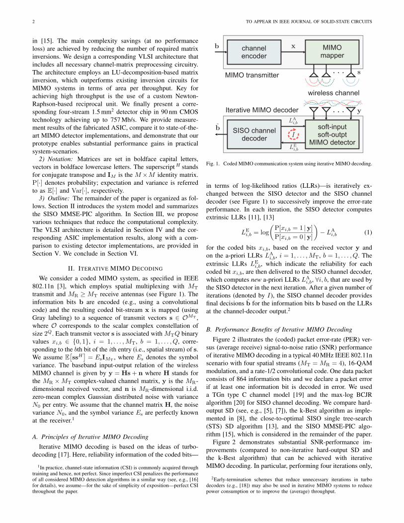
transmit and MR ≥MT receive antennas (see Figure 1). Theinformation bits b are encoded (e.g., using a convolutionalcode) and the resulting coded bit-stream x is mapped (usingGray labeling) to a sequence of transmit vectors s ∈ OMT ,where O corresponds to the scalar complex constellation ofsize 2Q. Each transmit vector s is associated with MTQ binaryvalues xi,b ∈ {0, 1}, i = 1, . . . ,MT, b = 1, . . . , Q, corre-sponding to the bth bit of the ith entry (i.e., spatial stream) of s.We assume E
[ssH
]= EsIMT , where Es denotes the symbol
variance. The baseband input-output relation of the wirelessMIMO channel is given by y = Hs + n where H stands forthe MR ×MT complex-valued channel matrix, y is the MR-dimensional received vector, and n is MR-dimensional i.i.d.zero-mean complex Gaussian distributed noise with varianceN0 per entry. We assume that the channel matrix H, the noisevariance N0, and the symbol variance Es are perfectly knownat the receiver.1
A. Principles of Iterative MIMO Decoding
Iterative MIMO decoding is based on the ideas of turbo-decoding [17]. Here, reliability information of the coded bits—
1In practice, channel-state information (CSI) is commonly acquired throughtraining and hence, not perfect. Since imperfect CSI penalizes the performanceof all considered MIMO detection algorithms in a similar way (see, e.g., [16]for details), we assume—for the sake of simplicity of exposition—perfect CSIthroughout the paper.
soft-inputsoft-outpt
MIMO detector
SISO channeldecoder
channelencoder
MIMOmapper
MIMO transmitter
Iterative MIMO decoder
wireless channel
Fig. 1. Coded MIMO communication system using iterative MIMO decoding.
in terms of log-likelihood ratios (LLRs)—is iteratively ex-changed between the SISO detector and the SISO channeldecoder (see Figure 1) to successively improve the error-rateperformance. In each iteration, the SISO detector computesextrinsic LLRs [11], [13]
LEi,b = log
(P[xi,b = 1 |y]P[xi,b = 0 |y]
)− LA
i,b (1)
for the coded bits xi,b, based on the received vector y andon the a-priori LLRs LA
i,b, i = 1, . . . ,MT, b = 1, . . . , Q. Theextrinsic LLRs LE
i,b, which indicate the reliability for eachcoded bit xi,b, are then delivered to the SISO channel decoder,which computes new a-priori LLRs LA
i,b, ∀i, b, that are used bythe SISO detector in the next iteration. After a given number ofiterations (denoted by I), the SISO channel decoder providesfinal decisions b for the information bits b based on the LLRsat the channel-decoder output.2
B. Performance Benefits of Iterative MIMO Decoding
Figure 2 illustrates the (coded) packet error-rate (PER) ver-sus (average receive) signal-to-noise ratio (SNR) performanceof iterative MIMO decoding in a typical 40 MHz IEEE 802.11nscenario with four spatial streams (MT = MR = 4), 16-QAMmodulation, and a rate-1/2 convolutional code. One data packetconsists of 864 information bits and we declare a packet errorif at least one information bit is decoded in error. We useda TGn type C channel model [19] and the max-log BCJRalgorithm [20] for SISO channel decoding. We compare hard-output SD (see, e.g., [5], [7]), the k-Best algorithm as imple-mented in [8], the close-to-optimal SISO single tree-search(STS) SD algorithm [13], and the SISO MMSE-PIC algo-rithm [15], which is considered in the remainder of the paper.
Figure 2 demonstrates substantial SNR-performance im-provements (compared to non-iterative hard-output SD andthe k-Best algorithm) that can be achieved with iterativeMIMO decoding. In particular, performing four iterations only,
2Early-termination schemes that reduce unnecessary iterations in turbodecoders (e.g., [18]) may also be used in iterative MIMO systems to reducepower consumption or to improve the (average) throughput.
STUDER, FATEH, AND SEETHALER 3
I=1I=1
I=2
I=2
I=4
I=8
Fig. 2. PER versus SNR performance of a coded MIMO system using variousiterative (using I ∈ {2, 4, 8} number of iterations) and non-interative (I = 1)MIMO detection algorithms.
enables to achieve 10% PER at 12 dB SNR for both SISOSTS-SD and SISO MMSE-PIC, compared to the more than18 dB SNR that is required by hard-output SD and the k-Bestalgorithm. Hence, four iterations improve the performance bymore than 6 dB SNR at IEEE 802.11n-relevant PERs. Notethat the SNR-performance gain from four to eight iterationsis only 0.25 dB, which indicates that performing more thanfour iterations does not pay off in practical systems. Weemphasize that the SNR-performance advantage of iterativeMIMO decoding ultimately leads to an increased systemthroughput (as higher data-rates can be used reliably at thesame SNR), better coverage, and improved range (since thelowest data-rate can be decoded reliably at lower SNR).
We finally note that SISO STS-SD outperforms SISOMMSE-PIC for a small number of iterations. However, theSISO STS-SD algorithm requires i) roughly 8× higher compu-tational complexity than SISO MMSE-PIC (cf. Section V-C3)and ii) SD-based algorithms exhibit—in contrast to the otherconsidered algorithms—a non-constant throughput stronglydepending on the SNR and the channel realization. Sincepractical MIMO receivers need to cope with varying channelconditions and transmission rates, the non-constant throughputrenders implementations of SD extremely difficult (see [7] fora corresponding discussion). Both drawbacks associated withSD finally led to our decision to favor the SISO MMSE-PICalgorithm for implementation.
C. SISO MMSE-PIC Algorithm
Even for a small number of spatial streams (say MT > 2),exact computation of the LLRs in (1) entails prohibitivelyhigh computational complexity. Therefore, a variety of sub-optimum algorithms has been proposed in the literature,e.g., [13], [15]. In this paper, we focus on the SISO MMSE-PIC algorithm initially proposed by Wang and Poor in1999 [15] in the context of multi-user detection. Since then,various algorithm optimizations have been proposed [21]–[24].The following five paragraphs summarize the SISO MMSE-PIC algorithm as described in [23].
1) Computation of Soft-Symbols: The algorithm starts bycomputing estimates si for i = 1, . . . ,MT (referred to as “soft-symbols”) for the transmitted symbols si according to [21]
si = E[si] =∑a∈O
P[si = a] a (2)
where P[si = a] =∏Qb=1 P[xi,b = k] denotes to the a-priori
probability of the symbol a ∈ O with k = [a]b referring to thebth bit associated with the symbol a. The reliability of eachsoft-symbol si is characterized by its variance
Ei = Var[si] = E[|ei|2
](3)
with ei = si − si. The a-priori probabilities involved in thecomputation of the soft-symbols (2) and their variances (3)are calculated on the basis of the a-priori LLRs LA
i,b deliveredby the channel decoder.3 According to [25], we have
P[xi,b = k] =12
(1 + (2k − 1) tanh
(12LAi,b
))(4)
which can be approximated efficiently in hardware throughtable look-ups.
As observed in [23], using intrinsic a-priori LLRs in thecomputation of (4) instead of the extrinsic ones leads, in gen-eral, to significantly better error-rate performance of the SISOMMSE-PIC algorithm. We therefore exclusively use intrinsica-priori LLRs for the computation of (4) throughout the pa-per. We finally note that for most Gray mappings (includingthat used in IEEE 802.11n) the soft-symbols in (2) and theircorresponding variances in (3) can be computed efficiently inhardware using the method proposed in [24].
2) Parallel Interference Cancellation (PIC): With the aidof the previously computed soft-symbols (2), the algorithmconsiders each of the i streams separately and cancels theinterference in y induced by all other streams j 6= i as follows:
yi = y −∑j,j 6=i
hj sj = hisi + ni (5)
where ni =∑j,j 6=i hjej + n corresponds to the remaining
noise-plus-interference (NPI).3) MMSE Filter-Vector Computation: In order to reduce
the NPI in each yi of (5), a linear MMSE filter is used. TheseMT MMSE filter vectors are computed according to [21]
wHi = EshHi A−1
i (6)
where
Ai = HΛiHH +N0IMR (7)
and Λi being an MT ×MT diagonal matrix having entries
Λj,j =
{Ej , j 6= i
Es, j = i.
It is important to realize that (6) requires the inversion of aMR ×MR-dimensional matrix for each of the MT streams,for each received vector, and for each iteration, which in-hibits an efficient implementation in hardware. In order tosubstantially reduce this computational burden, a novel low-complexity method is proposed in Section III.
3The LLRs are initialized as LAi,b = 0, ∀i, b, in the first iteration.
4 TO APPEAR IN IEEE JOURNAL OF SOLID-STATE CIRCUITS
4) MMSE Filtering: The MMSE filter vectors in (6) arethen used to reduce the NPI present in the PIC vectors yiin (5). The ith result of this filtering process corresponds to
zi = wHi yi = µisi + wH
i ni (8)
with µi = wHi hi.
5) LLR Computation: The algorithm finally approximatesthe LLRs LE
i,b by assuming that the MT single-input single-output systems in (8) are statistical independent and that theNPI term wH
i ni is Gaussian distributed with variance
ν2i = Var[zi] = wH
i
∑j,j 6=i
EjhjhHj +N0IMR
wi. (9)
The resulting intrinsic LLRs are then computed as [21]
LDi,b = log
∑a∈Z(1)
b
exp
(−|zi − µia|
2
ν2i
+Q∑b=1
(2[a]b − 1)2
LAi,b
)− log
∑a∈Z(0)
b
exp
(−|zi − µia|
2
ν2i
+Q∑b=1
(2[a]b − 1)2
LAi,b
) (10)
where Z(1)b and Z(0)
b refer to the subsets of O, where thebth bit is 1 and 0, respectively. Finally, approximations of theextrinsic LLRs in (1) are computed as LE
i,b = LDi,b − LA
i,b.
III. LOW-COMPLEXITY SISO MMSE-PIC ALGORITHM
The SISO MMSE-PIC algorithm described above is notwell-suited for an efficient implementation in hardware. Inparticular, the need for multiple matrix inversions per sym-bol vector entails high computational complexity and requiresconsiderable arithmetic precision. In order to alleviate theseissues, we next detail a variety of techniques enabling theeconomic implementation of the SISO MMSE-PIC algorithmin VLSI.
A. Exact MMSE-Filter Computation at Low-Complexity
Computation of the MT MMSE filter vectors in (6) requiresMT matrix inversions, which poses significant challenges foran efficient (in terms of area and throughput) implementation.To reduce the associated complexity, a variety of methods havebeen proposed in the literature, e.g., [21], [24]. More precisely,[21] proposes to sequentially perform rank-one updates, whichreduces the complexity required to compute all MT inversesA−1i in (6). The approach in [24] requires the computation of
MT matrices similar to (7), but only one row of each inverse.We next describe a novel approach for computation of all
MT MMSE filter vectors which involves the computation ofone matrix similar to (7) and requires a single matrix inversiononly. The derivation is detailed in Appendix A and amountsto computing
WH = A−1HH (11)
where A = HHHΛ +N0IMT with Λ denoting a MT ×MT
diagonal matrix having elements Λi,i = Ei, ∀i. The rows
wHi of WH correspond to the MMSE filter vectors in (6)
up to multiplicative constants. As shown in Appendix A, sucha scaling of the MMSE filter vectors does not affect the a-posteriori LLRs (10) delivered by the SISO MMSE-PIC al-gorithm. Consequently, the MMSE filter vectors wH
i can bereplaced by wH
i without loss in terms of error-rate perfor-mance. Furthermore, the computation of A−1 in (11) canbe performed in a numerically stable way (see Appendix B)and is therefore well-suited for fixed-point implementation. Insummary, our method requires MT times less inverses than thestandard approach described in Section II-C3 and also exhibitssignificantly smaller complexity than the methods proposedin [21], [24].
B. Efficient LLR Computation
1) Efficient NPI-Variance Computation: The first step forreducing the computational complexity associated with LLRcomputation (10) amounts to simplifying the computation ofthe NPI variance ν2
i (see (9) with wHi being replaced with
wHi ) based on the idea developed in [22]. As shown in Ap-
pendix C, ν2i can be simplified to ν2
i = µi − Eiµ2i using µi =
wHi hi, which requires roughly MR times less complex-valued
multiplications compared to that required by (9). We further-more simplify the computation of (8). To this end, we rewrite
|zi − µia|2
ν2i
(12)
in (10) as follows:
ρi |zi − a|2 (13)
where ρi denotes the post-equalization SINR on the ith streamgiven by
ρi =µ2i
ν2i
=µi
1− Eiµiand the MMSE filter output zi is computed as
zi =ziµi
=wHi yi
wHi hi
=wHi yiµi
.
2) Max-Log Approximation: So far, all considered tech-niques for complexity reduction do not have any impact onthe error-rate performance of the algorithm. Additional com-plexity reductions at the cost of a small performance loss(cf. Section V-B) is achieved by the application of the max-logapproximation [11] to (10) with (12) being replaced with (13),which gives
LDi,b ≈ min
a∈Z(−1)b
{ρi |zi − a|2 −
Q∑b=1
(2[a]b − 1)2
LAi,b
}
− mina∈Z(+1)
b
{ρi |zi − a|2 −
Q∑b=1
(2[a]b − 1)2
LAi,b
}. (14)
Computation of (14) avoids the evaluation of MT · 2 · |O| ex-ponential functions and only requires hardware-friendly min-imization operations.
STUDER, FATEH, AND SEETHALER 5
Algorithm 1 Low-Complexity SISO MMSE-PIC1: Compute the Gram matrix G = HHH and the matched-
filter output yMF = HHy.2: For i = 1, . . . ,MT, compute the soft-symbols si and
variances Ei as in detailed Section II-C1.3: Perform PIC (cf. (5)) based on yMF according to yMF
i =HH yi = yMF −
∑j,j 6=i gj sj , i = 1, . . . ,MT, where gj
denotes the jth column of G.4: Compute the inverse A−1 = (GΛ + N0IMT)−1 in (11)
with Λi,i = Ei, i = 1, . . . ,MT.5: Compute the MMSE filter outputs as zi = µ−1
i aHi yMFi ,
i = 1, . . . ,MT, where aHi is the ith row of A−1 andµi = aHi gi.
6: Compute the LLRs LEi,b, i = 1, . . . ,MT, b = 1, . . . , Q,
according to (15).
3) Omitting the Prior Term: Additional complexity reduc-tion is achieved by omitting the prior term
∑Qb=1
(2[a]b−1)2 LA
i,b
in (14). As shown in [26], this approximation does not resultin a performance loss for Gray-mapped BPSK and 4-QAMconstellations, and entails only a small loss for higher-ordermodulation schemes. Hence, we compute the extrinsic LLRsas
LEi,b = ρi
(mina∈Z(0)
b
|zi − a|2 − mina∈Z(1)
b
|zi − a|2). (15)
This expression can be rewritten as LEi,b = ρiλb(zi) with [27]
λb(zi) = mina∈Z(0)
b
|zi − a|2 − mina∈Z(1)
b
|zi − a|2 (16)
being a piecewise linear function for Gray mappings. Hence,(16) can be obtained efficiently in VLSI (see [16] for imple-mentation details).
C. Avoiding Redundant Computations
In order to avoid recurrent (and hence, redundant) compu-tations, we adopt an idea presented in [24] for our needs. Tothis end, we compute—prior to detection—the Gram matrixG = HHH and the matched-filter output according to yMF =HHy. The remaining computations are then performed onlyon the basis of G and yMF instead of on H and y, whichroughly halves the number of (complex-valued) multiplica-tions. The resulting procedure is summarized in Algorithm 1and referred to as the low-complexity SISO MMSE-PIC algo-rithm.
IV. VLSI ARCHITECTURE
In this section, we describe a VLSI architecture for the low-complexity SISO MMSE-PIC algorithm and detail the keysolutions required to achieve high-throughput with low area.
A. Architectural Overview
In order to achieve high throughput, we decided to parti-tion Algorithm 1 into eight subtasks which are executed in aparallel and (coarse-grained) pipelined fashion. The high-levelVLSI architecture—along with the partitioning of the involvedcomputations—is depicted in Figure 3. The architecture con-sists of eight processing units (PUs), where the six processingsteps of Algorithm 1 are mapped to the PUs as shown inFigure 3. The advantages of this architectural structure are:i) It enables to achieve a high sustained throughput and ii)each PU can be designed, optimized, and verified separately,eventually requiring low development and verification time.
The channel matrix H, the received vector y, the a-prioriLLRs LA
i,b, and the noise variance N0 are fed to the inputof the detector. Each PU performs the assigned computationsin Ts clock cycles and the results of each unit are passed tothe subsequent PU(s) (or to the output of the detector) everyTsth clock cycle, which is referred to as the “exchange-cycle.”Consequently, the architecture decodes six receive vectors con-currently and in a pipelined manner. Every Tsth cycle, thedetector delivers a new set of MTQ LLR values LE
i,b, resultingin a sustained throughput of
Θ =MTQ
Tsfclk [bit/s]. (17)
Since (17) scales linearly in the clock frequency fclk, thethroughput of the detector is maximized by minimizing thelength of the critical path of the whole design. In order to arriveat low silicon area while being able to exceed the 600 Mb/speak data-rate of IEEE 802.11n in 90 nm CMOS technology,we chose Ts = 18. This choice results in a processing latencyof 108 clock cycles and requires only 450 MHz to achieve thetarget throughput of 600 Mb/s.
The control unit (see Figure 3) handles the synchronizationbetween each PU and controls the input/output interface of thedetector. In order to operate the PUs with more than 450 MHzwithout the need of an on-chip PLL, we feed two clock signals(with 90° phase offset) into the decoder, which are then usedto generate—with the aid of an XOR-gate—an internal clocksignal of twice the frequency (see Figure 3). To reduce dy-namic power consumption in case that no data-frame needs tobe processed, the clock of each PU can be gated individually.
B. Architecture of the Processing Units
All PUs share the same architectural principle and performtheir assigned tasks in a time-shared fashion. The basis archi-tecture is depicted in Figure 4 and consists of a finite state-machine (FSM) controlling the data memory, a task-specificset of arithmetic units (AUs), and an interconnection networkdistributing the memory contents in parallel fashion to all AUs.In order to maximize the clock frequency and to minimizecircuit area, the detector exclusively employs fixed-point arith-metic. The AU and memory-internal word-lengths are opti-mized with the aid of numerical simulations (cf. Section V-B).The feed-through capability available in each PU allows for aparallel transfer of all the data-memory contents from one PUto the subsequent PU(s) during the exchange-cycle. Moreover,
6 TO APPEAR IN IEEE JOURNAL OF SOLID-STATE CIRCUITS
Gram matrix &matched filter
soft-symbols& variances
PIC part 1 PIC part 2
LU-decomp. &forward-subst.
back-substitution
MMSE filter &SINR comp.
LLRcomputation
data
input
data
outp
ut
controlunit
clockgates
control input
clock inputs
XO
R
Fig. 3. High-level VLSI architecture of the low-complexity SISO MMSE-PIC detector.
interconnectionnetwork
data memory
FSM
feed-through
data outputs
data inputs
AUAUAU
feed-back
Fig. 4. Architectural principle of the processing units (PU).
a feed-back path (see Figure 4) enables the AUs to imme-diately use computation results in the subsequent process-ing cycle. Additional reduction of the critical path by 1/3is achieved through the insertion of pipeline registers at theinput of each AU (see Figure 4). Moreover, some AUs alsopass computation results during the exchange-cycle to the nextPU, which reduces the number of idle AUs.
1) Arithmetic Units (AUs): The total set of AUs used inthe detector corresponds to (complex-valued) adders, multi-pliers, arithmetic shifters (mainly used for improving numer-ical precision), reciprocal units computing 1/x, and look-uptables (required in the reciprocal units and for approximationof P[xi,b = k] in (4)). The set of AUs instantiated in each PU isdetermined such that all required operations can be completedin exactly Ts = 18 clock cycles. Table I shows the breakdown
of AUs and memory requirements for each PU in order toquantify their complexity requirements. One can immediatelyobserve that the AUs are distributed in a balanced way over allPUs (except for both PIC units and the LLR computation unit),which confirms the effectiveness of the algorithm-partitioningscheme shown in Figure 3.
2) Data Memories: The data memories store all interme-diate values, vectors, and matrices. In order to support a highmemory bandwidth and to enable parallel access to multipledata words in an irregular manner, the memories are formedby arrays of flip-flops instead of using on-chip S-RAM macro-cells. We emphasize that such an implementation choice maylead to slightly sub-optimal results from a silicon-area perspec-tive, but eventually improves the throughput and simplifiesplacing and routing of the design. Note that the storage re-quirements in each PU are rather low (see Table I) and hence,the area overhead due to peripheral circuitry present in S-RAMmacrocells further reduces the advantages of S-RAMs in thisarchitecture [28].
C. LU-Decomposition-Based Matrix InversionThe main computational burden remaining in the low-
complexity SISO MMSE-PIC algorithm corresponds to com-putation of A−1 in (11). Since high-throughput matrix inver-sion using fixed-point arithmetic is a challenging task, a varietyof solutions for MIMO systems have been proposed in the lit-erature, e.g., [29]–[31]. As it was noted in [32], inversion basedon the LU-decomposition (LUD) exhibits—among the popularmatrix inversion algorithms used for MIMO detection—thesmallest number of arithmetic operations (even though noLUD-based architecture for MIMO systems has been de-scribed in the open literature). This complexity advantageled to the decision to employ an LUD-based matrix-inversionprocedure in our design.
The PU “LU-decomp. & forward-subst.” (see Figure 3) com-putes the LUD A = LU, with L and U being MT ×MT-dimensional complex-valued lower-triangular with Li,i = 1,
STUDER, FATEH, AND SEETHALER 7
TABLE INUMBER OF ARITHMETIC UNITS AND MEMORY REQUIREMENTS FOR EVERY PU
Arithmetic unit add. mult. shift LUT recip. mem. [kBit]
∀i, and MT×MT upper-triangular, respectively, using the in-place LUD algorithm described in [33]. Straightforward LUD-based matrix inversion amounts to inverting L and U sepa-rately, followed by computation of A−1 = U−1L−1. This ap-proach is, however, not efficient in terms of the involved num-ber of arithmetic operations and therefore, a more economicmethod is employed. In particular, the PU computing the LUDadditionally solves Lvi = ei for vi, i = 1, . . . ,MT, where eidenotes the ith unit vector, using a forward-substitution pro-cedure. Then, the subsequent PU performs back-substitutionUxi = vi for xi, i = 1, . . . ,MT, which finally yields thedesired inverse, i.e., A−1 = [ x1 · · · xMT ], at low complexity.We note that the LUD, and both forward- and back-substitution,only require additions, multiplications, and the computation ofreciprocals.
D. Newton-Raphson-Based Reciprocal Unit
At various steps of the algorithm (i.e., for the LUD andthe computation of the SINR ρi) division operations are re-quired. Such operations are, in general, not well-suited forfixed-point implementation and off-the-shelf division circuitsusually entail a large area, a large number of clock cycles,or a long critical path. Since our goal was to maximize theclock frequency of the detector, we decided to build a customAU that is able to compute reciprocals 1/x at high throughputwith a precision that keeps the implementation loss sufficientlysmall.
1) Algorithm: Implementations of reciprocal units com-monly consist of a look-up table (LUT) generating an initialguess for 1/x and a subsequent arithmetic circuitry performinga small number of Newton-Raphson iterations, e.g., [34],[35]. The procedure employed here starts by shifting theinput value x according to x = 2αx, α ∈ Z, such that0.5 ≤ x < 1. Since 1 < 1/x ≤ 2, the subsequent computationscan be carried out with improved numerical stability.4 Basedon an initial guess x0 of 1/x obtained from a LUT, KNewton-Raphson iterations according to xk+1 ← 2xk − xx2
k,k = 1, . . . ,K, are performed; the final result xK correspondsto an approximation of 1/x.
2) Architectures: In our design, the LUD needs to be com-puted in exactly Ts = 18 clock cycles. Hence, the recip-rocal unit was allowed to consume at most three clock cy-cles per reciprocal-value computation. In addition, our simu-
4Note that rescaling by 2−α is performed at later stages in the algorithmwith the aid of arithmetic shifters.
8 bit LUT
shift
2*x
input
outputs
4 bit LUT
shift
input
outputs
x^2
x^2
2*x
Fig. 5. Architecture of the sequential (left) and pipelined (right) Newton-Raphson-based reciprocal unit. The critical path of both architectures has beenhighlighted with a dashed line.
lations have shown that 15 bit precision (excluding the initialshift) is sufficient to arrive at a negligible implementation loss(cf. Figure 7). During the evaluation of potential architectures,we arrived at two solutions meeting the given constraints. Botharchitectures are depicted in Figure 5 and have been synthe-sized in 90 nm CMOS technology at maximum speed. Thesequential architecture (7.1 kGE5 area; 1.73 ns critical path)performs two Newton-Raphson iterations and requires a 4 bitLUT. The pipelined architecture (17.7 kGE area; 1.22 ns criti-cal path) performs a single iteration, but requires a 8 bit LUTand additional pipeline registers, eventually requiring 2.5×larger area than the sequential architecture. Since the ultimatedesign goal was to maximize the clock frequency of the wholedetector, we implemented the pipelined architecture. This de-cision finally moved the critical path of the whole detector toa 24 bit×28 bit multiplier in the back-substitution PU.
V. IMPLEMENTATION RESULTS
The low-complexity SISO MMSE-PIC algorithm, along withall improvements detailed in the previous sections, was fab-ricated in 90 nm (1P/9M) CMOS technology. Figure 6 showsthe chip micrograph with highlighted PUs.6 The ASIC is com-
5One gate equivalent (GE) corresponds to a 2-input drive-1 NAND gate.6Due to library constraints, no signal routing is used on the 9th metal layer.
8 TO APPEAR IN IEEE JOURNAL OF SOLID-STATE CIRCUITS
soft sym.& var.
LLRcomp.
PIC1 & 2
Gra
m m
atr
ix &
matc
hed filt
er
MM
SE
filt
er
& S
INR
LUD &
forward
back-subst.
I/O
Fig. 6. SISO MMSE-PIC chip micrograph with highlighted PUs (I/O refersto logic required for the input/output interface of the chip).
TABLE IIDETAILED AREA AND POWER BREAKDOWN OF THE ASIC
aDenotes logic used for the input/output-interface of the chip.bIncluding 6.94 mA leakage current.
pliant to the IEEE 802.11n WLAN standard [3], includes nec-essary preprocessing circuitry, and supports SISO detection offour spatial streams (i.e., MT = MR = 4) with BPSK, QPSK,16-QAM, and 64-QAM modulation.
A. ASIC Implementation Results
The fabricated chip has the following key characteristics(see also the comparison in Table IV).7 Its core area is1.5 mm2 (at 86% cell density) corresponding to 410 kGE. Adetailed area breakdown of the ASIC is shown in Table II.The PU performing MMSE filtering and SINR computationrequires roughly 25% of the total silicon area. An additional25% is occupied by both PUs performing the LUD andthe back-substitution procedure. Hence, the single matrix-inversion method proposed in Section III-A reduces the totalsilicon area by roughly a factor of two compared to a straight-forward implementation computing four inverses.
7All measurement results (for maximum clock-frequency and power con-sumption) were carried out on an HP 83 000 F660 VLSI test system. Stimuliand expected responses were generated off-line in Matlab. The design’s full-scan capability was used to verify that all ASIC prototypes were fabricatedwithout errors.
TABLE IIICOMPARISON WITH OTHER 4×4 MATRIX-INVERSION CIRCUITS
1) Throughput: The maximum (internal) clock frequencyis 568 MHz, which results in a peak throughput of 757 Mb/sper iteration (measured for uncoded four-stream transmissionusing 64-QAM).8 Hence, the detector achieves the (rate 5/6-coded) 600 Mb/s peak data-rate specified in IEEE 802.11n withmargin.9
2) Power Consumption: The power consumption10 ofthe ASIC is 189.1 mW, leading to an energy-efficiency of0.25 nJ/bit per iteration; the leakage current is 6.94 mA atnominal voltage. The power breakdown11 in Table IV showsthat the dynamic power consumption of each PU is roughlyproportional to the silicon area. Therefore, the “MMSE filter-ing & SINR comp.” PU and both PUs performing the LUD andback-substitution are the most power-consuming componentsof the chip.
3) LUD-Based Matrix Inversion: In order to highlight theeffectiveness of the proposed LUD-based matrix inversion, weseparately compare the achieved performance to other (ded-icated) inversion circuits for MIMO systems reported in theliterature [29]–[31]. For our implementation, we consider thearea of the PUs required to compute the matrix inversion. Thethroughput is measured in 4×4 matrix-inversions per second,given by T−1
s fclk. Table III shows that our implementationoutperforms all other solutions in terms of throughput (mea-sured in million inverses per second) by at least 5×. Withrespect kGE per throughput, our inversion method is 2.7×more efficient than the second best solution [29].
B. Fixed-Point Error-Rate Performance
In order to achieve near-optimal error-rate performance withfixed-point arithmetic, the word-lengths in the SISO MMSE-PIC architecture have been optimized using numerical simu-lations. The key parameters are as follows: We use 5 bit and6 bit for the input and output LLRs, respectively. The real
8The throughput of a SISO detector decreases linearly with the number ofiterations [36], e.g., for I = 2, our implementation achieves 378.5 Mb/s.Hence, in order to perform two iterations in a IEEE 802.11n-complianttransceiver, either two SISO MMSE-PIC instances are required or the iterativedetection feature may only be used for the 20 MHz bandwidth mode specifyingonly 288.9 Mb/s throughput.
9The detector achieves a rate 5/6-coded throughput of 631 Mb/s/iteration.10Measured at maximum throughput, Vdd =1.2 V core supply, T = 300 K,
and using typical stimuli (generated at 15 dB SNR for 16-QAM with i.i.d.Rayleigh fading channel matrices). Note that for the power measurementspresented in [1], i.i.d. uniformly distributed bits have been supplied to theinput of the detector.
11The individual power results have been measured by exploiting the clock-gating capability available for each PU.
STUDER, FATEH, AND SEETHALER 9
TABLE IVASIC IMPLEMENTATION RESULTS AND COMPARISON TO OTHER REPORTED MIMO DETECTORS
Publication This work Witte Wenk Burg Liao Wenk Shabany and Liuet al. [14] et al. [7] et al. [10] et al. [6] et al. [7] Gulak [8] et al. [9]
aTechnology scaling to 90 nm CMOS technology assuming: A ∼ 1/s2, tpd ∼ 1/s, and Pdyn ∼ (1/s)(Vdd/V′dd).
bAssuming MT = MR = 4 using 64-QAM and evaluating 100 nodes per vector.cThroughput is only achieved under “good channel conditions” [6] and hence, representing optimistic performance.dAssuming MT = MR = 4 using 64-QAM and evaluating 10 nodes per vector.eArea and power figures of the SISO MMSE-PIC chip include the necessary preprocessing circuitry.
I=1I=2I=4
I=8
Fig. 7. PER versus SNR performance of the SISO MMSE-PIC ASIC.
and imaginary parts of the channel matrix H and the receivedvector y are represented with 14 bit and 16 bit, respectively.The largest word-length within the design resides in the back-substitution PU and corresponds to 28 bit.
Figure 7 compares the PER versus SNR performance ofiterative MIMO decoding using the ideal (floating-point) al-gorithm as in [23], the low-complexity SISO MMSE-PIC al-gorithm detailed in Algorithm 1, and the corresponding (fixed-point) ASIC implementation. The same simulation settingsas in Section II-B are used here. Note that for I = 1,SISO MMSE-PIC detection coincides with soft-output MMSE
detection as used in [10]. One can observe a 0.5 dB to 1 dBperformance degradation resulting from the max-log approxi-mation and omitting the prior terms (see Sections III-B2 andIII-B3). The implementation loss compared to the (floating-point) max-log detector is, however, less than 0.2 dB SNR,which highlights results of the fixed-point optimizations car-ried out during the design of the ASIC. Finally, one canobserve an impressive SNR performance gain of more than8 dB SNR compared to (non-iterative) soft-output MMSEdetection at only four iterations, which enables us to concludethat using the SISO MMSE-PIC in combination with iterativeMIMO decoding enables significant SNR-gains in practicalsystem-scenarios.
C. Comparison to Recent MIMO-Detector Implementations
Table IV provides a comparison of our implemented SISOMMSE-PIC ASIC with the synthesis results of the SISO STS-SD algorithm presented in [14] and other state-of-the-art non-iterative MIMO detector implementations [6]–[10]. For alldesigns, we considered the implementation variants designedfor four-stream MIMO detection supporting 64-QAM.
1) Throughput: For the throughput figures reported inTable IV, we note that the implementations [6], [7], [14]achieve non-constant throughput, i.e., the decoding effortstrongly depends on the SNR and the realization of thechannel-matrix. Moreover, their worst-case complexity is, ingeneral, very high, which leads to a low aggregated through-put. In order to arrive at a fair throughput comparison, weassumed that the SISO and soft-output SD-based implemen-
10 TO APPEAR IN IEEE JOURNAL OF SOLID-STATE CIRCUITS
tations [7], [14] visit at most 100 nodes (e.g., by enforcingrun-time constraints [37]), leading to optimistic results for64-QAM (see [7] for details). Since hard-output SD roughlyrequires one magnitude lower complexity than soft-outputSD [37], we assume [7] to visit a maximum of 10 nodes perdecoded vector. For the design in [6], we used the throughputfigures stated in the paper, which are, however, only achievedunder “good channel conditions” and therefore, representoptimistic performance. In summary, the given throughputresults favor the implementations [6], [7], [14].
We can observe from Table IV that the throughput achievedby the proposed SISO MMSE-PIC implementation is compa-rable to that achieved by the detectors proposed in [6], [8] andonly about 50% smaller than that of [9], [10]. It is, however,important to note that our proposed implementation, as in con-trast to the implementations of [6], [8]–[10], supports iterativeMIMO decoding. Compared to the synthesis results of thesoft-output SD in [7] and the only SISO detector reported sofar [14], our detector achieves 8× and 16× higher throughput,respectively.
2) Silicon Area: For the silicon area results reported inTable IV, it is important to note that our low-complexitySISO MMSE-PIC implementation and the soft-output MMSEdetector implementation proposed in [10] contain the neces-sary preprocessing circuitry, i.e., the operations required todecompose the channel matrix prior to detection. All otherimplementations shown in Table IV require an additionalQR-decomposition of H, which roughly entails an addi-tional 250 kGE for IEEE 802.11n-compliant receivers (cf. [10]in Table IV). The missing preprocessing circuitry in [6]–[9],[14] is therefore reflected in lower silicon area, improvedhardware-efficiency, lower power consumption, and optimisticenergy-efficiency figures. If we incorporate the additionalpreprocessing area of 250 kGE for these designs, the siliconarea of the proposed low-complexity SISO MMSE-PIC imple-mentation is in-between that of the detector implementationsin [7], [8], [10] and those reported in [6], [9], [14].
3) Hardware-Efficiency: In terms of hardware-efficiency,we attain comparable results as in [6], [7]. We can, hence,conclude that our design is competitive to recently reportedsoft-output MIMO detectors (which are unable to support it-erative MIMO decoding and do not include the necessarypreprocessing circuitry). Compared to the SISO STS-SD im-plementation [14], we achieve 8× better hardware efficiency,which is a result of the low throughput achieved by SD-basedmethods in combination with 64-QAM.
4) Energy-Efficiency: Our detector exhibits 3× and 2×worse energy-efficiency compared to the designs in [6], [9]and the design in [8], respectively. The reason for this penaltyis mainly due to i) the preprocessing circuitry present inour design and ii) the fact that the SISO MMSE-PIC ASICsupports iterative MIMO decoding, whereas all other designsreporting energy-efficiency [6], [8], [9] are non-iterative.
VI. CONCLUSION
In this paper, we presented a novel low-complexity soft-input soft-output (SISO) minimum mean-square error (MMSE)
parallel interference cancellation (PIC) algorithm for systemsemploying iterative MIMO decoding. We described a corre-sponding VLSI architecture and implemented the first ASICof a SISO detector in 90 nm CMOS technology. The fabricatedchip includes all the necessary channel-matrix preprocessingoperations and exceeds the 600 Mb/s peak data-rate of theIEEE 802.11n WLAN standard.
The SISO MMSE-PIC ASIC was shown to enable signif-icant SNR gains over recently reported non-iterative MIMO-detector implementations, while being competitive with re-spect to achievable throughput and silicon area. These SNR-performance gains ultimately lead to improved link reliabilityand system throughput in practical system-scenarios. In sum-mary, the presented MIMO detector represents the next steptowards achieving close-to-optimal performance in wirelessMIMO communication systems and is therefore well-suitedfor transceiver designs where outstanding throughput and ex-cellent link-reliability are the ultimate design goals.
ACKNOWLEDGEMENTS
The authors would like to thank A. Burg, N. Felber, F.Gürkaynak, H. Kaeslin, and M. Wenk for their assistance dur-ing the ASIC design. Furthermore, the authors gratefully ac-knowledge the support from H. Bölcskei, W. Fichtner, andQ. Huang.
APPENDIX ASINGLE MATRIX INVERSION
In this section, we show that the standard MMSE filtervectors wH
i in (6) (see also [21]) can be replaced by
wHi = hHi
(HΛHH +N0IMR
)−1
(18)
without changing the output of the SISO MMSE-PIC algo-rithm. Consequently, the MT matrix inversions required tocompute the vectors wH
i can be replaced by a single matrixinversion.
The proof is accomplished by first showing that wHi =
wHi ci with ci being a real-valued constant and by subsequently
proving that the scaling with ci of wHi does not change the
output of the SISO MMSE-PIC algorithm. To this end, westate the Sherman-Morrison formula [38](
Ai + uvH)−1
= A−1i −
A−1i uvHA−1
i
1 + vHA−1i u
. (19)
with Ai given in (7). We furthermore set uvH = hi∆ihHi ,where u = hi and ∆i = Ei −Es. Note that (19) correspondsto A−1 in (18). With the definition (18) we obtain
wHi = hHi A−1
i −hHi A−1
i hi∆ihHi A−1i
1 + ∆ihHi A−1i hi
. (20)
Using (6) enables us to rewrite (20) according to
wHi = Es
−1wHi
(1 + ∆iEs
−1wHi hi −∆iEs
−1hHi wi
1 + ∆iEs−1wH
i hi
).
Furthermore, by noting that the terms wHi hi and hHi wi are
real-valued, we have wHi hi = hHi wi, which leads to wH
i =
STUDER, FATEH, AND SEETHALER 11
wHi ci with ci = 1/
(Es + ∆iwH
i hi)
being a real-valued andstream-dependent constant.
We next show that a scaling of wHi does not change the
LLRs provided by the SISO MMSE-PIC algorithm. The onlyterm in the computation of the SISO MMSE-PIC LLRs (10)that depends on the MMSE filter vector wH
i is
|zi − µia|2
ν2i
=
∣∣wHi yi − wH
i hia∣∣2
wHi
(∑j,j 6=iEjhjh
Hj +N0I
)wi
.
which can equivalently be written as
|zi − µia|2
ν2i
=
∣∣ciwHi yi − ciwH
i hia∣∣2
ciwHi
(∑j,j 6=iEjhjh
Hj +N0I
)wic∗i
for any real-valued and stream-dependent constant ci, whichconcludes the proof.
We finally note that (18) can be used to obtain all MT
MMSE filter vectors concurrently. To this end, replace the hHiin (18) by HH and compute
WH = HH(HΛHH +N0IMR
)−1
(21)
where WH = [ w1 · · · wMT ]H contains all MMSE filtervectors on its rows.
APPENDIX BNUMERICALLY STABLE INVERSE OF SMALL MATRIX
We show that WH in (21) can be written in the formof (11). In fact, the key drawback of (21) is that an MR ×MR
matrix needs to be inverted while (11) requires a matrix in-version of dimension MT ×MT only (note that MR ≥MT).
To this end, define H = HΛ12 , where Λ
12 is a real-valued
MT×MT diagonal matrix with Λ12i,i =
√Ei, ∀i and Λ
12 Λ
12 =
Λ. The matrix in (21) can now be rewritten as
WH = Λ−12 HH
(HHH +N0IMR
)−1
. (22)
Application of the singular-value decomposition [38] to thematrix inverse in (22), leads to [36]
WH = Λ−1(HHH +N0Λ−1
)−1HH (23)
which only requires to invert an MT ×MT matrix.Unfortunately, the formulation in (23) exhibits poor numer-
ical stability. Consider the case where near-perfect a-prioriinformation is available, i.e., the variances Ei ≈ 0, ∀i. Inthis case, the entries of Λ−1 will be arbitrarily large andhence, computation of the MMSE filter matrix would requirea prohibitively large dynamic range. We therefore rewrite (23)to [36]
WH =(HHHΛ +N0IMT
)−1HH (24)
which, in general, exhibits superior numerical stability.
APPENDIX CEFFICIENT NPI-VARIANCE COMPUTATION
The computation of the NPI variance ν2i (see (9) with wH
i
being replaced with wHi ) can be simplified as follows. Using
the definition of Λ (cf. (11)), we can write
ν2i = wH
i
(HΛHH − EihihHi +N0IMR
)wi
= wHi
(HΛHH +N0IMR
)wi − Ei
(wHi hi)2 (25)
where wHi hi ∈ R. From (18) it follows that
wHi
(HΛHH +N0IMR
)= hHi .
Consequently, (25) can be simplified to
ν2i = hHi wi − Ei
(wHi hi)2 = wH
i hi − Ei(wHi hi)2.
REFERENCES
[1] C. Studer, S. Fateh, and D. Seethaler, “A 757 Mb/s 1.5 mm2 90 nmCMOS soft-input soft-output MIMO detector for IEEE 802.11n,” inProc. IEEE Europ. Solid State Circuits Conf. (ESSCIRC), Sevilla, Spain,Sept. 2010, pp. 530–533.
[2] A. Paulraj, R. Nabar, and D. Gore, Introduction to Space-Time WirelessCommunications. Cambridge Univ. Press, 2003.
[3] IEEE Draft Standard; Part 11: Wireless LAN Medium Access Control(MAC) and Physical Layer (PHY) specifications; Amendment 4: En-hancements for Higher Throughput, P802.11n/D3.0, Sep. 2007.
[5] A. Burg, M. Wenk, M. Zellweger, M. Wegmueller, N. Felber, andW. Fichtner, “VLSI implementation of the sphere decoding algorithm,”in Proc. IEEE Europ. Solid State Circuits Conf. (ESSCIRC), Leuven,Belgium, Sept. 2004, pp. 303–306.
[6] C.-H. Liao, T.-P. Wang, and T. D. Chiueh, “A 74.8 mW soft-outputdetector IC for 8×8 spatial-multiplexing MIMO communications,” IEEEJ. Solid State Circuits, vol. 45, no. 2, pp. 411–421, Feb. 2010.
[7] M. Wenk, L. Bruderer, A. Burg, and C. Studer, “Area- and throughput-optimized VLSI architecture of sphere decoding,” in Proc. IEEE/IFIPInt. Conf. VLSI and System-on-Chip (VLSI SoC), Madrid, Spain, Sept.2010.
[8] M. Shabany and P. G. Gulak, “A 0.13 µm CMOS, 655 Mb/s 4×4 64-QAM k-best MIMO detector,” in Dig. Techn. Papers, IEEE ISSCC, SanFrancisco, CA, USA, Feb. 2009, pp. 256–257.
[9] L. Liu, F. Ye, X. Ma, T. Zhang, and J. Ren, “A 1.1-Gb/s 115-pJ/bitconfigurable MIMO detector using 0.13-µm CMOS technology,” IEEETrans. Circ. Systems II, vol. 57, no. 9, pp. 701–705, Sept. 2010.
[10] A. Burg, S. Haene, M. Borgmann, D. Baum, T. Thaler, F. Carbognani,S. Zwicky, L. Barbero, C. Senning, P. Greisen, T. Peter, C. Foelmli,U. Schuster, and P. Tejera, “A 4-stream 802.11n baseband transceiver in0.13 µm CMOS,” in Dig. Techn. Papers, Symp. on VLSI Circuits, Kyoto,Japan, Jun. 2009, pp. 282–283.
[11] B. M. Hochwald and S. ten Brink, “Achieving near-capacity on amultiple-antenna channel,” IEEE Trans. Comm., vol. 51, no. 3, pp. 389–399, Mar. 2003.
[12] L. Boher, R. Rabineau, and M. Hélard, “FPGA implementation of aniterative receiver for MIMO-OFDM systems,” IEEE J. on Sel. Areas inComm., vol. 26, no. 6, pp. 857–866, Aug. 2008.
[13] C. Studer and H. Bölcskei, “Soft–input soft–output single tree-searchsphere decoding,” IEEE Trans. Inf. Th., vol. 56, no. 10, pp. 4827–4842,Oct. 2010.
[14] E. M. Witte, F. Borlenghi, G. Ascheid, R. Leupers, and H. Meyr, “Ascalable VLSI architecture for soft-input soft-output single tree-searchsphere decoding,” IEEE Trans. Circ. Systems II, vol. 57, no. 9, pp. 706–710, Sept. 2010.
[15] X. Wang and H. V. Poor, “Iterative (turbo) soft interference cancellationand decoding for coded CDMA,” IEEE Trans. Comm., vol. 47, no. 7,pp. 1046–1061, Jul. 1999.
[16] S. Häne, “VLSI circuits for MIMO-OFDM physical layer,” Ph.D.dissertation, ETH Zürich, Switzerland, 2008.
12 TO APPEAR IN IEEE JOURNAL OF SOLID-STATE CIRCUITS
[17] C. Berrou, A. Glavieux, and P. Thitimajshima, “Near Shannon limiterror-correcting coding and decoding,” in Proc. IEE Int. Conf. on Comm.(ICC), Geneva, Switzerland, May 1993, pp. 1064–1070.
[18] J.-H. Kim and I.-C. Park, “A unified parallel radix-4 turbo decoderfor mobile WiMAX and 3GPP-LTE,” in Proc. IEEE Custom IntegratedCircuits Conf. (CICC), San Jose, CA, USA, Sept. 2009, pp. 487–490.
[19] V. Erceg et al., TGn channel models, May 2004, IEEE 802.11 document03/940r4.
[20] L. R. Bahl, J. Cocke, F. Jelinek, and J. Raviv, “Optimal decoding oflinear codes for minimizing symbol error rate,” IEEE Trans. Inf. Th.,vol. 20, no. 2, pp. 284–287, Mar. 1974.
[21] M. Tüchler, A. C. Singer, and R. Koetter, “Minimum mean squared errorequalization using a priori information,” IEEE Trans. Sig. Proc., vol. 50,no. 3, pp. 673–983, Mar. 2002.
[22] A. Dejonghe and L. Vandendorpe, “Turbo-equalization for multilevelmodulation: an efficient low-complexity scheme,” in Proc. IEE Int. Conf.on Comm. (ICC), vol. 3, New York City, NY, USA, Apr. 2002, pp. 1863–1867.
[23] M. Witzke, S. Bäro, F. Schreckenbach, and J. Hagenauer, “Iterativedetection of MIMO signals with linear detectors,” in Proc. AsilomarConf. on Signals, Systems and Computers (ACSSC), Monterey, CA,USA, Nov. 2002, pp. 289–293.
[24] A. Tomasoni, M. Ferrari, D. Gatti, F. Osnato, and S. Bellini, “A lowcomplexity turbo MMSE receiver for W-LAN MIMO systems,” in Proc.IEE Int. Conf. on Comm. (ICC), vol. 9, Istanbul, Turkey, Jun. 2006, pp.4119–4124.
[25] J. Hagenauer, E. Offer, and L. Papke, “Iterative decoding of binary blockand convolutional codes,” IEEE Trans. Inf. Th., vol. 42, no. 2, pp. 429–445, Mar. 1996.
[26] S. Fateh, “VLSI implementation of soft-input soft-output MMSE parallelinterference cancellation,” Master’s thesis, Dept. Information Technol-ogy and Electical Engineering, ETH Zürich, Mar. 2009.
[27] I. B. Collings, M. R. G. Buttler, and M. McKay, “Low complexityreceiver design for MIMO bit-interleaved coded modulation,” in Proc.IEEE 8th Int. Symp. on Spread Spectrum Techniques and Applications(ISSSTA), Sydney, Australia, Aug. 2004, pp. 12–16.
[28] P. Meinerzhagen, C. Roth, and A. Burg, “Towards generic low-powerarea-efficient standard cell based memory architectures,” in Proc. IEEE53th Int. Midwest Symp. on Circuits and Systems (MWSCAS), Seattle,WA, USA, August 2010, pp. 129–132.
[29] A. Burg, S. Häne, D. Perels, P. Luethi, N. Felber, and W. Fichtner,“Algorithm and VLSI architecture for linear MMSE detection in MIMO-OFDM systems,” in Proc. IEEE Int. Symp. on Circuits and Systems(ISCAS), Kos, Greece, May 2006, pp. 4102–4105.
[30] J. Eilert, D. Wu, and D. Liu, “Implementation of a programmable linearMMSE detector for MIMO-OFDM,” in IEEE Int. Conf. on Acoustics,Speech, and Sig. Proc. (ICASSP), Las Vegas, NV, USA, March 2008,pp. 5396–5399.
[31] S. Eberli, D. Cescato, and W. Fichtner, “Divide-and-conquer matrixinversion for linear MMSE detection in SDR MIMO receivers,” in Proc.IEEE NORCHIP, Trondheim, Norway, Nov. 2008, pp. 162–167.
[32] S. Eberli, “Application-specific processor for MIMO-OFDM software-defined radio,” Ph.D. dissertation, ETH Zürich, Switzerland, Series inMicroelectronics, vol. 200, Hartung-Gorre Verlag Konstanz, 2009.
[33] G. H. Golub and C. F. van Loan, Matrix Computations, 3rd ed. TheJohns Hopkins Univ. Press, 1996.
[34] B. Gestner and D. V. Anderson, “Single Newton-Raphson iteration forinteger-rounded divider for lattice reduction algorithms,” in Proc. IEEE51th Int. Midwest Symp. on Circuits and Systems (MWSCAS), Knoxville,TN, USA, Aug. 2008, pp. 966–969.
[35] R. Zimmermann, “Computer arithmetic: Principles, architectures, andVLSI design,” Lecture notes, Integrated Systems Laboratory, Dept.Information Technology and Electrical Engineering, ETH Zürich, Tech.Rep., Mar. 1999.
[36] C. Studer, “Iterative MIMO decoding: Algorithms and VLSI implemen-tation aspects,” Ph.D. dissertation, ETH Zürich, Switzerland, Series inMicroelectronics, vol. 202, Hartung-Gorre Verlag Konstanz, 2009.
[37] C. Studer, A. Burg, and H. Bölcskei, “Soft-output sphere decoding:Algorithms and VLSI implementation,” IEEE J. Sel. Areas Comm.,vol. 26, no. 2, pp. 290–300, Feb. 2008.
[38] R. A. Horn and C. R. Johnson, Matrix Analysis. Cambridge Univ.Press, 1985.