UNCLASSIFIED AD NUMBER AD871466 NEW LIMITATION CHANGE TO Approved for public release, distribution unlimited FROM Distribution authorized to U.S. Gov't. agencies and their contractors; Critical Technology; 20 APR 1970. Other requests shall be referred to Naval Air Systems Command, ATTN: AIR-5104D, Washington, DC 20362. AUTHORITY NAVAIR ltr dtd 6 Apr 1977 THIS PAGE IS UNCLASSIFIED
Transcript
UNCLASSIFIED
AD NUMBER
AD871466
NEW LIMITATION CHANGE
TOApproved for public release, distributionunlimited
FROMDistribution authorized to U.S. Gov't.agencies and their contractors; CriticalTechnology; 20 APR 1970. Other requestsshall be referred to Naval Air SystemsCommand, ATTN: AIR-5104D, Washington, DC20362.
NAVY CONTRACT NOJ. NOw Ga1- C .p! _eBell Aerospace Company
COLOR ILLUSTRATIONS REPRODUCEWI IN BLACK AND WHITE
BELL AEROSPACE COMPANY
Buffalo, Ntw 'k,14240
647: 70: 0420-1: HCM- 20 April 1970
Letter No. 1473
TO: Commander, Naval Air Systems CommandDepartment of the NavyMain Navy BuildingWashington, D. C.- 20360.
ATTENTION: AIR-5104D
SUBJECT: Contract NOw 63-0118-ciX-22A R:-search AircraftFinal Progress Report No. 73April - December 196,
REFERENCE: (a) Navy Contract NOw 6 3-011 8 -ciSection F) -5
(b) Navy Contract NOw 63-0118-ciMod. 59, dated 8 0,.tober 1969
ENCLOSURE: (A) Five copies of Final Progress ReportNo. 73 kApril - December 1969)BAC No. 2127-933073
VIA: Mr. J. PattersonDCRB - DRGFC1021 Main StreetBuffalo, New York 14203
Enclosure (A), the 73rd X-22A Progress Report, is submitted in accord--ance with References (a and b) and covers the period 1 April through31 December 1969.
The report is considered as final as the aircraft development programwas completed and delivered in the 2nd quarter of 1969. The remainingtasks of temporary storage and aircraft No. 1 disassembly and all othercontract deliverable items were completed prior to 31 December 1969.
As this is the 73rd and final report, a Summary of X-22A DevelopmentFlight Test has been incorporated to reflect the full design and teststory of this successful V/STOL research aircraft.
BELL A OSPACE COMPANY
11. C. Marqirdt'
Project D'ecri -X-22A
re.cc: See attached sheets
ft
BELL AEROSPAGE ,COMPANY
Buffalo, New York 14240
647:70:0420-1:HCM20 April 1970Letter No. 1473Page 2
Distribution List
for X-22A (Final) Progress RQport
AIR FORCE ARMY
Headquarters Commanding GeneralUnited States Air Force USA Material CommandDepartment of the Air Force Building T-7Washington, D. C. Department of the ArmyAtten: AFRAE - 1 copy Washington, D. C. - 2 copies
Headquarters Commanding OfficerAir Force Systems Command U. S. Army Material Labs.Andrews Air Force Base, Md. Ft. Eustis, Va. Atten: SAVFE-AAAtten: SCTR - I copy kV/VROL Branch) - 2 copies
Hq AFSC (SCTSM/Capt. Jones) Commanding GeneralAndrews Air Force Base USA Test & Evaluation CommandWashington, D. C. 20331 - 1 copy Aberdeen Proving Ground, Md.
Atten: Lt. Col. French - 3 )cP *Aeronautical Systems DivisionWright Patterson Air Force Base DCASOOhioAtten: ASZTV - 10 copies Major Robert Cranston, Chief
Defense Contract AdministrationMajor R. L. Hammond Service OfficeHeadquarters USAF (AFXSAGP) 1021 Main StreetU. S. Air Force Buffalo, New York 14203 - 1 2pyWashington, D. C. - 1 copy
DCRB - DRGFCHeadquarters MAC (MAORQ) 1021 Main StreetScott Air Force Base Buffalo, New York 14203St. Louis, Illinois 62225 - 1 copy Atten: Mr. J. Patterson - I opyChief, Weapson Sys. Panel Div., DCS/O
NASALt. Col. Gay E. JonesAFFTC/FITOP National Aeronautics and Spac-. A6Edwards Air Force Base U. S. Air Force BaseEdwards, California - 1 copy Langley Field, Virginia - 1 .orr
ARMY Mr. Mark W. Kelly, Actg. Chic,Large Scale Aerodynamics Bran-h;
Office, Chief of Research & Develop. National Aeronautics and Soacr AcDepartment of the Army Ames Research CenterWashington, D. C. Moffett Field, Calf. 94035 - :Atten: Air Mobility Div. - 1 copy
L
( BELL AEROSPACE COMPANYBuffalo, New York 14240
647: 70:0420-1:HCM20 April 1970Letter No. 1473Page 3
NASA
Headquarters, National Aeronauticsand Space AdministrationWashington, D. C.Atten: Dir. of Aeronautics - 1 copy
FAA
Development Officer, SD-21Aircraft Development ServiceFederal Aviation AgencyWashington, D. C. 20553 - 1 copy
NAVY
Commander, Naval Air Systems CommandDepartment of the NavyMain Navy BuildingWashington, D. C. 20360Atten: AIR-5104D - 5 copies (Direct)
Commander, Naval Air Test CenterU. S. Naval Air StationPatuxent River, Maryland - 2 copies
Capt. Norm McLaughlinOffice of the Deputy Chief of Naval Operations (Development)Department of the NavyPentagonWashington, D. C. 20360Attention OP-722 - 1 copy
Bull Aerospace Company.M.WO.O i1
POST OFFICE BOX 1 BUFFALO. NEW YORK 14240
X-22A TRI-SER VICE V/STOL AIRCRAFT LJ*
r FINAL PROGRESS REPORT Oj-d
(INCLUDING FLIGHT TEST SUMMARY) -J>
Report No. 2127-933073 81L
F - 4April-December 1969
mcMWu uatfd ~m rx' va
This is the seventy-third Progress Report as required in Section F (5) of the contract.Late In 1968 this reporting provision was changed by NAVAIR Contract direction.
This seventy-third report outlines progress for the period 1 April 1969 through 31December 1969. For a brief introduction of the X-22A Program refer to reports prior
r to May 1964.
I* b ou d *bae w b
B.C. Ma qyrdiProject~rector'I: X-22A Program
Bell Aerospace Company
* CONTE NTS
Section Page
I SUMMARY .................................... I
II SUMMARY OF X-22A DEVELOPMENT FLIGHT TEST ....... 6A. 'Outstanding Features of the X-22A Aircraft ........... 6
B. General Specification .......................... 8
C. Program Introduction .......................... 10D. X-22A Milestones ............................ 10E. Development Programs ......................... 11F. Flight Test Program .......................... 15G. Military Pilot Evaluations ....................... 35
III TEST PROGRAMS ............................... 37A. Flight Test and Operations ...................... 37
B. Open Items ................................. 49
Report No. 2127-933073 ii
Bell Aerospace Company
ILLUSTRATIONSI.
Figure Page
1 Final MPE Completion .............................. 22 Aircraft Acceptance ............................. 33 X-22A One Aircraft Program Schedule ........ 5
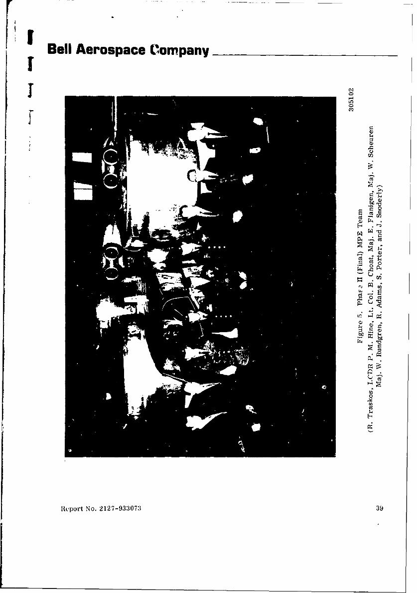
4 Rate of Descent Characteristics ..... ................. 285 Phase II (Final) MPE Team ......................... 396 X-22A MPE II Flight Tests .............. .. 407 Acceptance Speakers ................................. 448 Acceptance Group ....... ...................... 459 DCAS Group ...................................... 46
10 Bell-Navy Group ............................. 47
Report No. 2127-933073 iil
Bell Aerospace Company
1. SUMMARY
This report covers the nine-month period from 1 April 1969 through essential
program completion 31 December 1969. Activities were highlighted with two major
milestones in the second quarter of 1969, the final Military Pilot Evaluation (MPE)
and the aircraft acceptance by NAVAIR. The remainder of the period represented
effort completing final reports, the "live" storage of the X-22A pending new contract
flying, and the disassembly of Aircraft No. 1 for salvageable spare parts. As these
tasks were for all practical purposes completed, this report is being issued as a final
progress report at the calendar close of 1969.
During April, the Phase II final MPE (Figure 1) took place. Following ground
school training and cockpit checks, eleven flights totaling twelve hours were flown on
six consecutive days with five military pilots flying the aircraft. The MPE critique
of 11 April produced no majbr discriepancies. Later in the month, a post MPE meeting
was held at NAVAIR to discuss the MPE preliminary conclusions.
Following the close of the MPE, the aircraft was removed from flight status to
ready it for the planned 2 May delivery. At the post MPE meeting and through April,
the delivery and acceptance status of the vehicle was discussed. The Navy requested
an acceptance date shift from the second to the sixteenth of May. The Bell hangar
crew was reduced to one shift on the aircraft to comply with this stretch out. Plans
leading to aircraft delivery ultimately formalized a date of 19 May as requested by
NAVAIR for a group of Navy and DCASO representatives to be at Bell. Contractual
delivery and a fo,-mal acceptance ceremony were completed that day (Figure 2).
Following Navy acceptance the aircraft was placed in temporary "live" storage
pending new contract authorization. A seven-week strike at Bell ensued from 9 June
through 25 July during which time the aircraft status was monitored in the hangar by
supervisory personnel.
Report No. 2127-933073
r Bell Aerospace Company _ _ _ _ _ _
4-Z
v!-
0A.P0d
ta CL _
04
0
Report No. 2127-933u732 j
Bell Aerospace Company
4S
Cd
Cd
-; 0
Repor No. 127-93073
Bell Aerospace Company
-~ During the March through May period, Bell and NAVAIR continued discussing the
proposed three year follow-on program. As this program was not materializing,
J" an interim pilot training program was planned as a new contract effort to follow air-
craft delivery and precede the follow on. The interim program was subsequently
j authorized to start 18 August as a separate contract for ground school and flight train-ing for three pilots and evaluation flying for two NASA pilots. The X-22A was supplied
" t to this new contract as GFE and reporting for this program was made separate from
this report. Through this interim-program Bell pursued the initiation of the follow-on
jeffort and it now appears that work may begin on the follow-on program in the second
quarter of 1970.
Differences of contractual position arising from the removal of Aircraft No. 1
from flight status and the Navy decision to withdraw it from the program and not to
repair or replace it, led to the Armed Services Board of Contractors Appeal (ASBCA)decision and stipulafion of 6 June 1968. Since that tme Bell continued active efforts
to conclude the matter. During the period of June and July 1969 concerted efforts
with NAVAIR Contracts formulated a settlement. This was contractually finalized
with Contract Modification No. 59, dated 9 October 1969.
In May 1969, the Navy directed disassembly of Aircraft No. 1 to be accomplished
Iunder the basic contract. This effort has culminated in an inventory of parts for pos-
sible later reconditioning as spares.
On 12-13 August NAVAIR personnel were at Bell to discuss final contract re-porting and flight test data requirements. Contractual and program report efforts
during the past months have now been completed. This report concludes that phase.The Contractors efforts are currently concentrated on the disposal and disposition
of the last details of residual inventories, tooling, etc. Figure 3 shows the program
schedule to essential completion during the calendar year 1969.
POWER PLANTNo. & Model (4) YT58-GE-8DMfr. General Electric Co.Type Free Power TurbineReductionGear Ratio 0.133Prop Mfr. Hamilton StandardProp. Dia. 84 in.No. of Blades 3Tail Pipe Fixed Area
werael4tabll" temegae P3 i akfle 04 Rmvbeadisengage P4 Engine support bum Pockteesst
C4 Throte PS 1181gione igtCg jagelr rp.m. P4 Twop c cowlings 06 Cast acrylic WalsCil Undrara sletoer W7Frwa@ Canopy openI"a-wtrCy Pd aussent it EngO output) shaltn acC11 Varlbl rtiohl-rank control at A- co o*
C9 W P.- TT sgn geI o W.--=WRdo-dslteisalto
CIO Control rnn oo propeller and T2GabxspotbxGi1 flaarw'deretactieleven P.C.Us 3 Laea d*4~ 710 l-- 1 Nusewboky
CI DEkon power ton"ro unit T4Atmi0ero 14 Malnwheel bayCI, sAcsoysax(i puevon 5l Main entry doorCla hydrauon puins, colrfndie 16 Emergency e-itC13,m 02r, Cins., air xinuihe
C14 7ft diameter Hamilton Stanard Gl Flee&.'hfta etInhapropeller T7 Support bearing G198 Nal.i igCIF StOe spline 0
unt ( et)Til propeller gearbox (2.590 r.p.m. 11 prple r.pi.Cie Duct rttinInterconnecting shaft output) n Lateral and longitudinal AS I degreesC19 Duct rotation shaft brake T12 Gearbox oil tankIC0 Bota (propeller pitch) control TIO Gearbox oil auy0= reakersCiI Duct support tube Ti41 Oil cooler and an14 CiciDbekr
CU uctsupor tue eern;TIS Oil cooler air exhaust 14cis fg ositio indiatrCS CDnuiucal an eorigcn-".
C3 r Vaiabstbly syto Je. etsn ip 17 Varlableoetabllity system potentlo-
Pd Jett iso potrletrs::PS jettison pipe 1*844) Low-rage airspeed sensor
BELL X-22A ...
0-
-VV
C11
Bell Aerospace Company'8
.................................. .. . ......
.44
.........
. . . . . . . . . . . .. .......
...
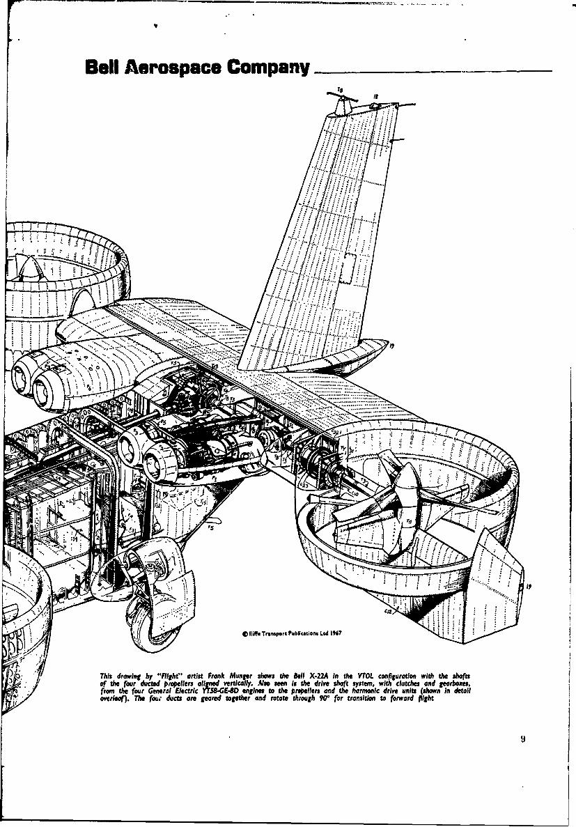
This drawing by "Flight" artist Frank Munger shows the Bell1 X-22A In the VTOL canfliguration with the shoftsof the four ducted propellers allge vertically. Also seen is the drive shaft system, with clutches and gearboxres,from the four General Electric ATSR-GE.8D engines to the propellers and the harmonic drive units (shown in detilloverloof). The fou, ducts are geared together and rotate through 90* for transition to forward Pight
Bell Aerospace Company
C. PROGRAM INTRODUCTION
The X-22A is a V/STOL aircraft which utilizes the dual tandem ducted propeller
propulsion system arrangement. As one of the Tri-Service family of V/STOL aircraft,
it has been developed under the direction of the Naval Air Systems Command.
The purposes of the X-22A program are several: first, the prime goal of the
contract was the demonstration of a complete transition which .as been accomplished
many times. Second, to provide an aircraft for future flight research and the evalua-
tion of the unique and potentially advantageous dual tandem ducted propeller configu-
rations. Another very important purpose emphasized by the Navyas the program
developed, to provide through design specifications and program objectives, a highly
versatile aircraft capable of general research on V/STOL handling qualities using a
Variable Stability System designed and developed specifically for the X-22A.
Bell Aerospace has in the past successfully developed VTOL aircraft such as the
Air Test Vehicle (ATV), the first jet VTOL. Success with the ATV led to a USAF
contract to build the X-14 VTOL, which has been modified to the X-14A and has been
flying since 1959. Further studies produced contracts for the D188A/XF-109 fighter-
bomber and D190B utility and rescue aircraft which progressed to the full-size
mockup stage. The Lunar Landing Research Vehicle (LLRV) and Lunar Landing
Training Vehicles (LLTV) are additions to Bell's V/STOL capabilities. This back-
ground and experience has been utilized in the development of the X-22A aircraft
systems.
D. X-22A PROGR AM MILESTONES
Contract Date 30 November 1962
Design Completion January 1965
Rollout No. 1 Aircraft May 1965
Rollout No. 2 Aircraft October 1965
Propulsion System Test Stand February-June 1965
Aircraft No. 2 Tie Down Test February-May 1966
Report No. 2127-933073 10
Bell Aerospace Company
First Flight No. 1 Aircraft* March 1966
First Flight No. 2 Aircraft January 1967
Public V/STOL Transition Demonstration May 1967
Completed Transition Envelope Expansion June 1967
First Militar Pilot Evaluatin (MPE) January 1968
Completed High Speed Flutter Testing August 1968
Completed Structural Flight Test Demonstrations August 1968
Initial Variable Stabilty Flight Testing September 1968
Completed Variable Stability Flight Testing March 1969
Final MPE April 1969
Navy Aircraft Acceptance 19 May 1969
*No. 1 Aircraft was removed from flight status in August 1966 when damaged in landing.
The Navy redirected the program to accomplish the test objectives with the oneremaining aircraft.
E. DEVELOPMENT TEST PROGRAMS
1. Wind Tunnel Tests
(a) David Taylor Model Basin: 1/6 scale unpowered test in 8 x 10 ft windtunnel.
(b) Aero-elastic powered model evaluation at DTMB.
(c) 1/3 scale ducted propeller model test in the 8 x 10 ft wind tunnel atDTMB.
(d) NASA Langley Research Center - 1/5 scale powered model in 17 footsectiou of 7 x 10 ft wind tunnel.
(e) Free spin model evaluation in NASA Langley spin tunnel.
(f) 0.18-scale free-flight model tested in the Langley full scale wind tunnel.
(g) Full-scale ducted propeller tests in the NASA Ames full-scale wind tunnel.
2. Airframe Static Test
The structural design of the X-22A airframe was proven by ultimate load
tests of the pr!mary structural components. The following listed major assemblies were
subjected to the full ultimate design loading conditions:
Report No. 2127-933073 11
Bell Aerospace Company(a) Engine Mount,
(b) Vertical Fin,
(c) Wing,
(d) Aft Duct,
(e) Fuselage Group,
(f) Landing Gear Installation.
No failures of primary structure occurred during the entire Static Test program
and no problems were evidenced during the structural flight test demonstration program
which followed.
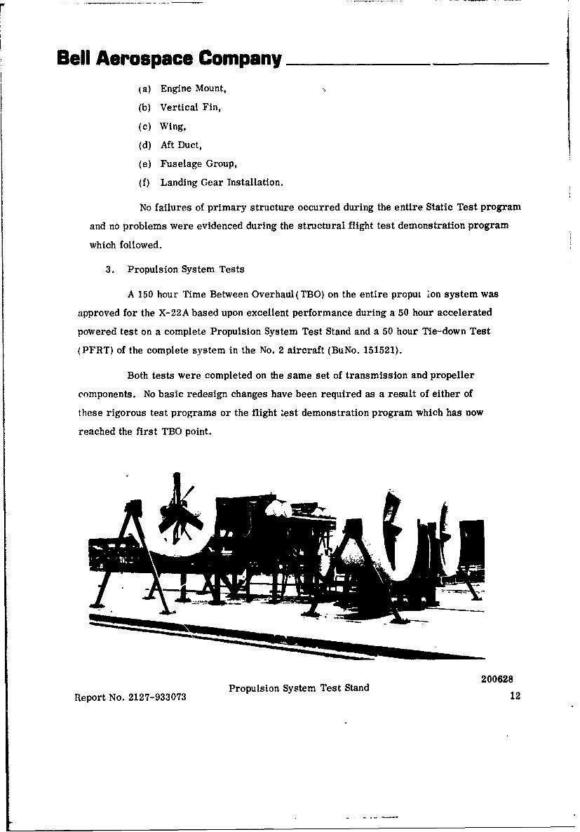
3. Propulsion System Tests
A 150 hour Time Between Overhaul(TBO) on the entire propul ion system was
approved for the X-22A based upon excellent performance during a 50 hour accelerated
powered test on a complete Propulsion System Test Stand and a 50 hour Tie-down Test
(PFRT) of the complete system in the No. 2 aircraft (BuNo. 151521).
Both tests were completed on the same set of transmission and propeller
components. No basic redesign changes have been required as a result of either of
these rigorous test programs or the flight test demonstration program which has now
reached the first TBO point.
200628
Report No. 2127-933073 Propulsion System Test Stand 12
Bell Aerospace Company
I"A
1
r.10ft08
Tie-Down Test Stand 210908
4. Control System and Hydraulic Test Stand
A complete full scale Control System Test Stand (CSTS) was constructed todevelop and check out all elements of the X-22A control system including the hydraulic
supply system, elevon and propeller actuation systems, duct rotation system, control
phasing and stability augmentation systems, electrohydraulic feel and trim system,and the Variable Stability System (VSS). When connected with the analog simulation ofthe X-22A the CSTS was used to perform pilot evaluations of various failure modes
during operation of the basic aircraft control system and also during variable stability
operation. Several thousand hours of operation on the CSTS served to confirm the
integrity of the complete system under actual operating conditions.
Report No. 2127-933073 13
Bell Aerospace Company
LMi2
tt
Control System Test Stand 204592
5. ESCAPAC l-D-1 Ejection Seat Qualification
The ejection seat system for the X-22A has been qualified by a successful
series of actual seat firings by Bell Aerospace and NAEC. In all, fourteen ejections
were conducted, seven static ejections and seven ejections at various airspeeds (up
to 250 kots). The final eight firings were conducted to qualify the seat with the
DART (Directional Automatic Realignment of Trajectory) seat stabilization and snubber
system installed.
6. X-22A Six Degree of Freedom Hybrid Flight Simulation
A very valuable tool developed during the X-22A program is the piloted
real time six-degree-of-freedom (6 DOF) simulation of the aircraft which gives a
representation of the X-22A during the complete flight envelope of hover, transition
at intermediate duct angles and forward flight with ducts horizontal. The simulation
was used extensively to establish control system design values of control phasing,
Report No. 2127-933073 14
Bell Aerospace Companycontrol sensitivitv, stability augmentation, feel forces, and control harmofiy. The
simulator was then used to familiarize and train the pilots to hover, transition and
maneuver the aircraft prior to flight. A wide variety of control system failure cases
were simulated for pilot evaluation and training. The Hybrid Simulation was used to
familiarize the MPE pilots with the flight characteristics of the X-22A prior to the
actual MPE flighcs.
F. FLIGHT TEST PROGRAM
3035751. Contractor Flight Test Statistics (As of 19 May 1969)
Total X-22AItem Program
Flights 220
Flight Time 113 hours
VTO 386
VL 405
Transitions 185
STO 216
SL 197
Airframe Time 430 hours
All flights were at Bell Aerospace facilities at Niagara Falls International
Airport,
Report No. 2127-933073 15
Bell Aerospace Company
2. Chronology
a. 1966
January through December 1966 - Zero to 3.2 hours flight time:
The No. I Aircraft was ground checked and readied for the initial X-22A hover flight.
This took place on 17 March 1966 and was followed with basic systems checkout and
familiarization flights. The initial STOL flight was completed 30 June and initial
zero degree duct flight 22 July.
On flight 15, 8 August, a double hydraulic malfunction resulted in
a hard emergency landing which damaged the aircraft. The Navy decision not to
rehbud the aircraft removed it from flight status. The program in 1967 was re-
directed to accomplish the program objectives with the one remaining aircraft.
Report No. 2127-933073 16
Bell Aerospace Company
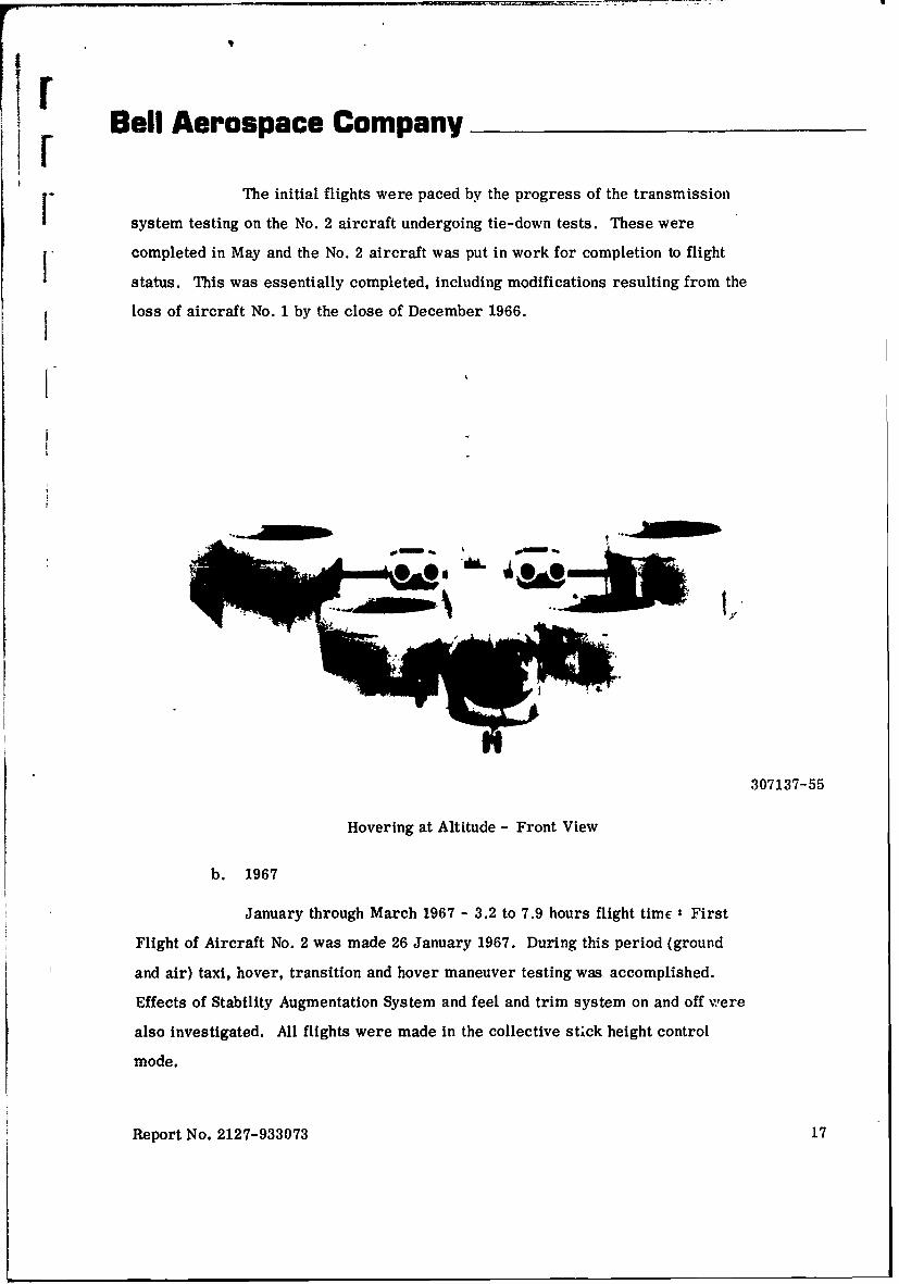
The initial flights were paced by the progress of the transmission
system testing on the No. 2 aircraft undergoing tie-down tests. These were
completed in May and the No. 2 aircraft was put in work for completion to flight
status. This was essentially completed, including modifications resulting from the
loss of aircraft No. 1 by the close of December 1966.
I -
tat
307137-55
Hovering at Altitude - Front View
b. 1967
January through March 1967 - 3.2 to 7.9 hours flight time: First
Flight of Aircraft No. 2 was made 26 January 1967. During this period (ground
and air) taxi, hover, transition and hover maneuver testing was accomplished.
Effects of Stability Augmentation System and feel and trim system on and off were
also investigated. All flights were made in the collective stick height control
mode.
Report No. 2127-933073 17
Bell Aerospace Company
.1071:37-1
STOL Landing Approach - 0cDuct Angle
April through .June 1967 - 7.9 to 21.4 hours flight time: Th1c aircraft
was cleared for 150 knot speed with landing gear down. Flights were made around
the field within a five mile radius. 'Ile propeller stress surNvey was completed and
longitudinal stability was investigated at 5000 feet altitude. STOI. takeoffs and climbs
to altitudes of -15001 feet were demonstrated and dynamic longitudinal stability was
investigrated. Evaluation of static dIirectional and lateral stability was conducted.
O ther conditions inmestigated wvere 400)0 ft 'min. descent. three-engine
one engine out) vertical takeoff and hover, conventional takeoff -ind landing, pull-ups
and push-overs . VSS data flights and STOL'()l hover and] transition proficiency flights
were made. The collective tia anle con)t rol s\ stem was used for all above tests.
Additional tests were performed in the ST( i. and hoveri modes with the power control
system . A puhi ic flight demoast ratioro of the N- 22 A was successfully accomplished
on 9 May 1967.
Report No. 2127- 933073 1
r r
Bell Aerospace Company
July through December 1967 - 21.4 to 32.9 hours flight time: The
master control was checked out and flight tests performed for evaluation. Taxi,
hover, STOL, VTOL and cruise mode flights were made. Static longitudinal stability
was investigated for range of speed and duct angles. Power trim change was evaluated.
Cor'.inuous maximum duct rotation rate transitions from hover to conventional flight
and from conventional flight back to hover were accomplished without difficulty.
Landing gear cycling was performed at hover, 80, 100 and 125 knots.
In addition, military power STO, airspeed calibrations, temperature and
vibration surveys, and hover tasks were performed. Structural demonstration points
up to 2 g, aircraft flutter clearance out to 220 knots, and propeller blade stress surveys
out to 200 knots were completed. The one-hundredth flight milestone of Aircraft No. 2
was accomplished on 19 December 1967, less than 11 months from first flight. The
aircraft completed the prescribed flight demonstrations to enable the Military Pre-
liminary Evaluation (MPE) to be scheduled during the month of January 1968.
30713:7-62
Hoverin" at Altitude - Side View
Report No. 2127-933073 19
Bell Aerospace Company
c. 1968
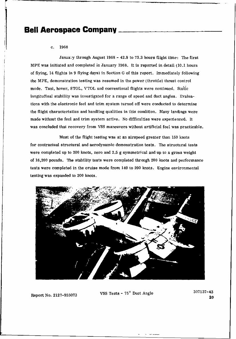
Januar'y through August 1968 - 42.9 to 73.3 hours flight time: The first
MPE was initiated and completed in January 1968. It is reported in detail (10.1 hours
of flying, 14 flights in 9 flying days) in Section G of this report. Immediately following
the MPE, demonstration testing was resumed in the power (throttle) thrust control
mode. Taxi, hover, STOL, VTOL and conventional flights were continued. Static
longitudinal stability was investigated for a range of speed and duct angles. Evalua-
tions with the electronic feel and trim system turned off were conducted to determine
the flight characteristics and handling qualities in this condition. Many landings were
made without the feel and trim system active. No difficulties were experienced. It
was concluded that recovery from VSS maneuvers without artificial feel was practicable.
Most of the flight testing was at an airspeed greater than 150 knots
for contractual structural and aerodynamic demonstration tests. The structural tests
were completed up to 200 knots, zero and 2.5 g symmetrical and up to a gross weight
of 16,200 pounds. The stability tests were completed through 200 knots and performance
tests were completed in the cruise mode from 140 to 200 knots. Engine environmental
During flights 87-128, J. Spencer was checked out as the new Bell
first pilot. By flight 151 another Bell test pilot, R. Carlin, was checked out as second
pilot of the Bell team.
Minimum ground roll STOL takeoffs at maximum power were made
with extremely rapid acceleration. Ground roll and steep climbout at 20-degrees
nose-up attitude was attained. Aircraft rotation was made at a speed or 40 knots and
a 3000 fpm rate of climb was attained while airspeed increased to a stable 60 knots
during climb. Minimum ground roll STOL takeoffs were continued to decrease the
distance cver a 50-foot obstacle.
Performance tests to evaluate hovering ceiling were made at 300,
2000, 4000, 6000, and 8000 foot altitudes. A new hover altitude record (.000 feet)
was set using the LORAS (low range airspeed system) to obtain zero airspeed.
Handling characteristics were exceptionally good. Airspeed could be held exactly
laterally and within ±1 knot longitudinally. Hovering at altitude on irstruments was
very easy using the LORAS. A simulated engine failure was demonstrated success-
fully while hovering at 4000 ft.
Report No. 2127-933073 21
r
Bell Aerospace Company
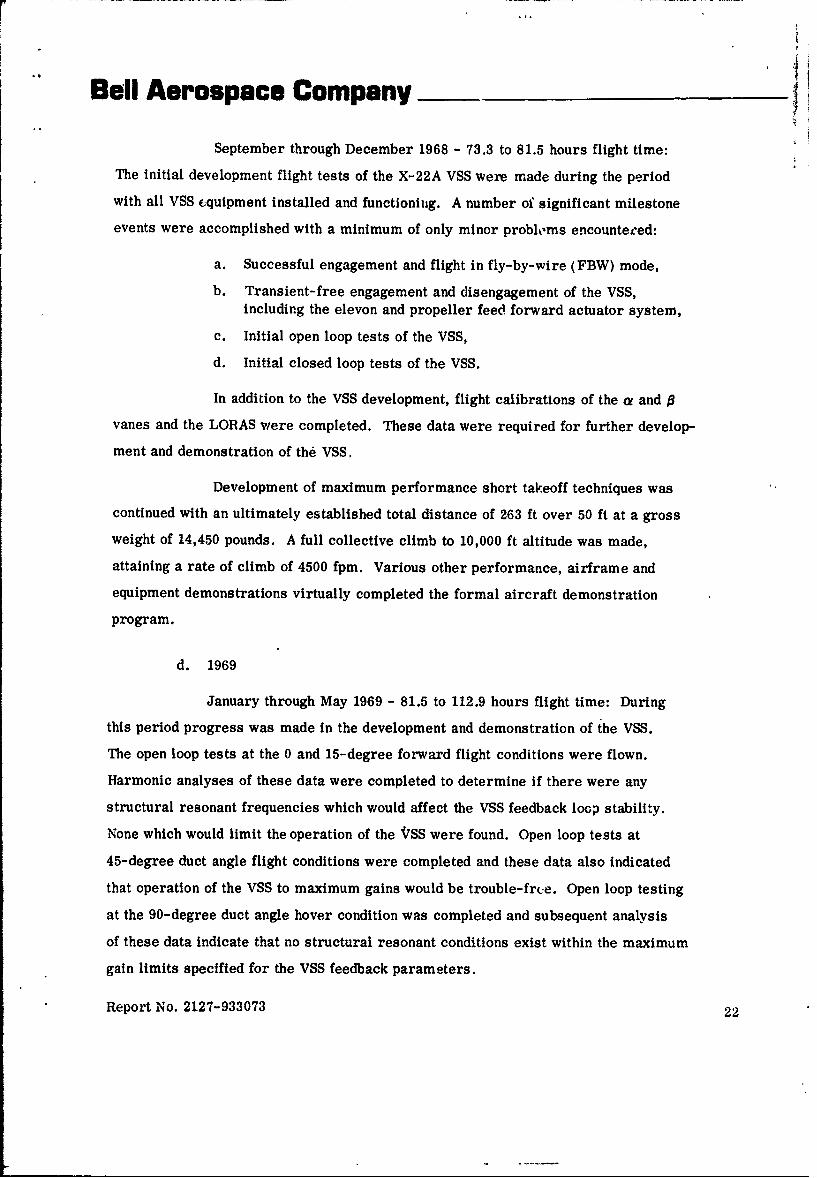
September through December 1968 - 73.3 to 81.5 hours flight time:
The initial development flight tests of the X-22A VSS were made during the period
with all VSS cquipment installed and functioning. A number of significant milestone
events were accomplished with a minimum of only minor probhms encountered:
a. Successful engagement and flight in fly-by-wire (FBW) mode,
b. Transient-free engagement and disengagement of the VSS,including the elevon and propeller feed forward actuator system,
c. Initial open loop tests of the VSS,
d. Initial closed loop tests of the VSS.
In addition to the VSS development, flight calibrations of the ct and 6
vanes and the LORAS were completed. These data were required for further develop-
ment and demonstration of the VSS.
Development of maximum performance short takeoff techniques was
continued with an ultimately established total distance of 263 ft over 50 ft at a gross
weight of 14,450 pounds. A full collective climb to 10,000 ft altitude was made,
attaining a rate of climb of 4500 fpm. Various other performance, airframe and
equipment demonstrations virtually completed the formal aircraft demonstration
program.
d. 1969
January through May 1969 - 81.5 to 112.9 hours flight time: During
this period progress was made in the development and demonstration of the VSS.
The open loop tests at the 0 and 15-degree forward flight conditions were flown.
Harmonic analyses of these data were completed to determine if there were any
structural resonant frequencies which would affect the VSS feedback loop stability.
None which would limit the operation of the VSS were found. Open loop tests at
45-degree duct angle flight conditions were completed and these data also indicated
that operation of the VSS to maximum gains would be trouble-frue. Open loop testing
at the 90-degree duct angle hover condition was completed and subsequent analysis
of these data indicate that no structural resonant conditions exist within the maximum
gain limits specified for the VSS feedback parameters.
Report No. 2127-933073 22
Bell Aerospace Company
VSS Tests - 300 Duct Angle
With clearance obtained from analysis of the open loop data, closed
loop tests of significant VSS feedback parameters were conducted. The majority of
significant feedback parameters for the level flight condition were inserted into
the aircraft control characteristics by the VSS digitrols to the maximum gain in the
direction of increased aircraft stability. A number of feedback variable loops in the
90-degree hover condition were also closed. The aircraft flight characteristics were
changed as expected with the pilots able to control the altered configurations encountered.
The foregoing flight characteristics cases were set up for the final
MPE in April 1969. It is reported in detail (12 hours of flying, 11 flights, 6 flying days)
in Section G of this report. Following the MPE the aircraft was prepared for accept-
ance by the Navy at Bell 19 May 1969.
Report No. 2127-933073 23
Bell Aerospace Company
307137-12
VSS Evaluations - 750 Duct Angle
3. Performance Summary
Performance Flight Demonstration Data for the completed X-22A contract
tests have been furnished to the Navy in Bell Reports 2127-931002, the final being
Revision G. The following tabulation represents the projented capabilities of the
X-22A based upon data computed for the aircraft configured without prototype and
test installations.
Report No. 2127-933073 24
Bell Aerospace Companyr" Maximum Maximum
* Endurance Range AtSea Level Optimum Altitude
TAKEOFF WEIGHT lb 16,452 16,452Fuel internal/external lb/lb 3,196* 3,196*Payload lb 1,200 1,200Stall speed - power-off knot 98.2 98.2Takeoff run at Sea Level - calm ft 0 0
Takeoff run at Sea Level - 25 knot wind ft 0 0Tbkeoff to clear 50 ft - calm ft 0 0Rate of climb at Sea Level fpm 4,550 4,550Service Ceiling (100 fpm) ft 27,000 27,000Combat range n.mi. - 386
Average cruising speed knot - 185Cruising altitude(s) ft - 11,000/15,000
50 Level Constant50 X 4,0 JJ --Altitude Transition/
40 -
30
20 0 0000*00010 ___
0- 20 0 20 40 60 80 100 120 140 160
Airspeed - Knots
Report No. 2127-933073 26
Bell Aerospace Company
b. Short Takeoff
STOL at all duct angles have been performed and no operational limita-
tions exist.
Flighte Path
1<11. 4000 ft/minRate of Climb
0 50ft
GroundLine
S113 ft -P* 150 ft
0 Ground Roll 40 59Knots Knots Knots
Profile of a Typical Maximum Performance Short Take-Off
Duct Angle 300Gross Weight 14,450 lbs
c. Terminal Area Operati,..d
Steep descent path landing approach angles exceeding 20 degrees at all
the selected duct angles, and fully controlled vertical descents exceeding 1600 feet per
minute have been flown. The positive control exhibited by the X-22A at all speeds and
duct angles throughout the extremely large transition envelope all the way down to the
runway is very impressive. These capabilities coupled with the use of the Variable
Stability System to vary flight characteristics make the X-22A uniquely suited for
terminal area operations investigations. (See Figure 4.)
Report No. 2127-933073 27
Bell iorospace Company
C')
09=-I
o '.
$43
0.0
4-44U~b 00
.T.
Repot No212793303 2
Bull Aerospace Companyr
d. Downwash Characteristics
Downwash was measured under the X-22A in hovering flight. Measure-
ments were confirmed by previous model tests and surveys.
The flight test measurements show that a nominal hover heights of 50
to 100 feet, downwash characteristics are reasonable. The aircraft has a unique four
element slipstream and ground impingement flow system. A feature of this flow system
is the area of relatively still air (with some updraft and/or outflow) under the aircraft
in the region of confluence of the radial flows from the fans' impinging slipstreams.
With the aircraft hovering at 100 feet, the test engineer had no difficulty
in moving about under the aircraft. At both 50 and 100 feet hover altitudes, a region
of very low velocity, almost near calm, was reported directly under the aircraft.
100 ft
HorizontalVelocities
___ - 10mp5.0 ft L17 mph
2.S. ft 30mph
Downwash Characteristics of the X-22A Aircraft
Report No. 2127-933073 29
Bell Aerospace Company
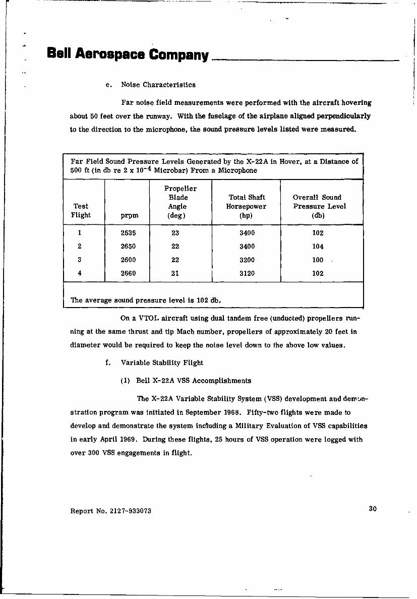
e. Noise Characteristics
Far noise field measurements were performed with the aircraft hovering
about 50 feet over the runway. With the fuselage of the airplane aligned perpendicularly
to the direction to the microphone, the sound pressure levels listed were measured.
Far Field Sound Pressure Levels Generated by the X-22A in Hover, at a Distance of500 ft (in db re 2 x 10
- 4 Microbar) From a Microphone
PropellerBlade Total Shaft Overall Sound
Test Angle Horsepower Pressure LevelFlight prpm (deg) (hp) (db)
1 2535 23 3400 102
2 2650 22 3400 104
3 2600 22 3200 100
4 2660 21 3120 102
The average sound pressure level is 102 db.
On a VTOL aircraft using dual tandem free (unducted) propellers run-
ning at the same thrust and tip Mach number, propellers of approximately 20 feet in
diameter would be required to keep the noise level down to the above low values.
f. Variable Stability Flight
(1) Bell X-22A VSS Accomplishments
The X-22A Variable Stability System (VSS) development and denvjn-
stration program was initiated in September 1968. Fifty-two flights were made to
develop and demonstrate the system including a Military Evaluation of VSS capabilities
In early April 1969. During these flights, 25 hours of VSS operation were logged with
over 300 VSS engagements in flight.
Report No. 2127-933073 30
Bell Aerospace Company
After installation of the VSS equipment, extensive ground checking
and calibrations were performed of all sensors, basic flight controls, feed forward
system, safety monitors, and the VSS equipment.
To check the system for stability when fitted to the airframe, open
loop tests were performed. This was accomplished by engaging the VSS with the feed-
back parameter gains set to zero. The system feedback outputs were recorded and
v analyzed in response to abrupt control inputs to determine over what range of gains
feedback loops could be closed. These tests were performed at 00 and 900 duct angles
with spot checks made at intermediate duct angles.
Following this analysis, the significant feedback parameter loops
were closed and gains incrementally increased one parameter at a time. The results
of these tests were compared with the open loop data before progressing to the maxi-
mum specified gains. Following these tests, combinations of feedback parameters
were incorporated to change specific dynamic characteristics as a final system
demonstration.
The contract demonstrations were completed in April 1969 with a
very successful MPE in which the participating pilots acted as evaluation pilots and
experienced the wide spectrum of stability and control and handling qualities produced
by the VSS equipment. The following page lists all of the feedback variables provided
in the VSS.
Five military pilots accomplished this evaluation during eleven
flights, totaling twelve hours of flight time, within six working days.
The X-22A has made 220 development flights and, with its VSS, is
a well developed research tool with very few operational limitations throughout a
flight envelope from zero to 200 knots. Bell has a continuing effort to develop better
methods of utilizing the equipment through modern computer analysis techniques. A
preliminary effort has yielded a method which shows great promise in being applicable
to the computation of the feedback gains. Due to the large number of feedback signals,
all combinations of available gains will never be completely evaluated but as research
Report No. 2127-933073 31
Bell Aerospace Company
programs progress, additional knowledge of system characteristics will continuously
be gathered making the tool more useful.
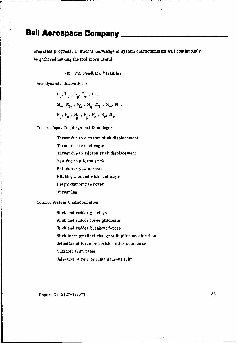
(2) VSS Feedback Variables
Aerodynamic Derivatives:
Lv LO9 Lp , L , Lr,v j3' p r
M, M M&,M , M, Mmw a q M q w
N, N , N. , N, N N Nv 03 p p 0 ' r' V'
Control Input Couplings and Dampings:
Thrust due to elevator stick displacement
Thrust due to duct angle
Thrust due to aileron stick displacement
Yaw due to aileron stick
Roll due to yaw control
Pitching moment with duct angle
Height damping in hover
Thrust lag
Control System Characteristics:
Stick and rudder gearings
Stick and rudder force gradients
Stick and rudder breakout forces
Stick force gradient change with pitch acceleration
Selection of force or position stick commands
Variable trim rates
Selection of rate or instantaneous trim
Report No. 2127-933073 32
Bell Aerospace Company[
5. Summary of Pilot Comment
a. VTOL and Hover Operation
The airplane exhibits very good positive static and dynamic stability in
hover out of ground effect and can be flown hands off for long periods. It has excellent
control response about all axes and has good height control. Ground effect is positive,
mildly turbulent. Vertical takeoffs and landings are easily performed. All hovering
maneuvers are much easier to perform than in most helicopters. Various fuselage
attitudes can be maintained as a function of the hovering duct angle selected while
hovering.
b. STOL Operation
Thirty-degree duct angle takeoffs and landings are accomplished with
ease within the 90 degree crosswind limitations of the airplane of 15 knots. Touchdown
attitude of approximately 5 degrees affords excellent visibility. There is no tendency
to swerve with the ground roll nearly straight. Without the benefit of nose wheel
steering, takeoffs and landings have been made at various duct angles between 0 and
90 degrees. Accurate landing touchdown points are the rule rather than the exception.
Duct rotation is used after landing to eliminate residual thrust and to obtain aerodynamic
braking.
c. Conventional Flight
The aircraft has good handling characteristics with very crisp response
about all axes even though the static stability is neutral to slightly negative. The
characteristics are comparable to a high performance fighter aircraft. Flying without
Stability Augmentation System (SAS) and without Feel and Trim presents no difficulty.
d. Transition
Flying the aircraft within the transition envelope is very comfortable.
Duct rotation is used simply as another flight control to change spetd or adjust fuse-
lage attitude at constant speed. There are no special procedures or schedules to be
complied with when transitioning. Ducts can be rotated in either direction at the
pilot's discretion to obtain the desired response.
Report No. 2127-933073 33
rBell Aerospace Company
e. Stability Augmentation System
The rate stabilization system of the airplane assists the pilot immensely
in the hover arid transition modes of flight. Hovering has satisfactorily been accom-
plished without SAS although the pilot workload is increased. STOL landings without
SAS are accomplished with ease.
f. Ground Effect
Ground effect is mildly turbulent, but positive. A slight loss in yaw
control power is noticed while hovering in ground effect. At certain combinations of
duct angles and wind speeds, ground effect dissipates and disappears.
g. Control Mode (Collective)
Control of power is linear and power response is excellent. Power
management is good in forward flight and altitude control is excellent in hover.
h. Control Mode (Power)
No noticeable or adverse reaction is apparent while moving a handful
of throttles versus a single collective pitch stick to perform a vertical takeoff or
landing. A longer time constant makes altitude control in the hover slightly difficult
but power control in forward flight is conventional with no difficulties experienced.
i. Variable Stability Operation
(1) Engagement to fly-by-wire (FBW) or VSS modes is easily accom-plished and transient free.
(2) Flight characteristics in FBW mode appear comparable to thebasic X-22A control system mode.
(3) The unaltered (zero feedback gains) VSS mode is identical to thebasic X-22A except for the faster response of a tighter controlsystem.
(4) The VSS safety monitor system will trip the VSS out and revertcontrol to the safety pilot if certain preset limits are exceededor a failure is detected.
(5) The insertion of variable feedback parameters can drasticallyalter the flight characteristics of the X-22A.
Report No. 2127-933073 34
Bell Aerospace CompanyIr G. MILITARY PILOT EVALUATIONS
1. Phase I MPE - (3 January 1968 through 31 January 1968)
SThe first Military Preliminary Evaluation team, consisting of 13 pilots and
engineers from the three services, arrived at Bell on 3 January 1968, for one week of
jGround School and Simulator Training to preceed flying.
The evaluation flying proceeded rapidly with the on'y major delays due to
weather. The crew on the first three flights was composed of one military and one
Bell Aerosystems pilot. During the remaining eleven flights of the evaluation, full
military crews operated the X-22A. Five military pilots accomplished the evaluation
during the fourteen flights totaling approximately ten hours of flight time.
With the extensive instrumentation available on the X-22A, the evaluation
team was able to obtain very complete information on the static and dynamic stability
characteristics of the aircraft throughout transition envelope. These are the flight
regimes in which the X-22A will be used to perform its basic VTOL research missionusing the Variable Stability System. Comments received indicated that the aircraft
was meeting its design requirements and is very well suited for this research role.
First Military Pilot Evaluation Flights
(11- 31 January 1968)
Total Flights 14Total Flight Time 10:08Total VTO 25Total VL 24Total Transitions 31Total STO 5Total SL 6Pilots Lt. Comdr. W. Davies, USN
Maj. W. Rundgren, USAMaj. J. Basquez, USAFLt. D. Green, USNLt. W. Casey, USN
Report No. 2127-933073 35
Bell Aerospace Company __
2. Phase II MPE (31 March 1969 through 9 April 1969) (Final)*
The second Military Preliminary Evaluation team consisted of five pilots
from all branches of service. Its purpose was to evaluate the Variable Stability
System capabilities of the X-22A aircraft. After a two-day ground school, flight
testing was conducted on a two-flights-a-day basis over a six-day period. All
flights except one were flown with a military pilot as evaluation pilot and a Bell
pilot as safety pilot. The one exception was flown with militr , pilots as both evalua-
tion and safety pilots.
Variable stability parameters were varied to provide a total of 18 different
configurations at duct angles of 00, 300 , 450, and 900. Individual parameters were
changed to the limits of the pilot's capability to control the aircraft in the unstable
direction and to the specification limits or maximum gain available in the stable
direction. The successful results of the MPE demonstrated the ability of the VSS
to markedly change the basic characteristics of the X-22A, and to prove its potential
as a research tool in the V/STOL field.
Second Military Pilot Evaluation Flights
(2- 9 April 1969)
Total Flights 11Total Flight Time 12 hoursTotal VTO 6Total VL 9Total Transitions 23Total STO 12Total SL 9Pilots Maj. W. Scheuren, USMC
Lt. Col. B. Choat, USAMaj. W. Rundgren, USAMaj. E. Flanigen, USAFI,CDR. P. Hine, USN
*Reported in detail in following Section III Test Program pages
Report No. 2127-933073 36
Bell Aerospace Company
III. TEST PROGRAMS
A. FLIGHT TEST AND OPERATIONS
1. BuNo. 151520 (Bell No. 1 Aircraft)
The air'frame and components of the damaged aircraft had remained consolidated
and covered in the Bell Aerospace Company hangar since August 1966. As reported in
prior progress reports a proposal was prepared and transmitted to NAVAIR in January
1969. An early authorization was anticipated to accomplish this disassembly and salvage
of the possible spares for the aircraft in parallel w th the remaining flight test operations
activity. The proposal continued under review at NAVAIR until late in May at which time
direction was received for Bell to initiatework.
At this writing, the inventory of salvaged parts is being prepared for contract
conclusion. Items relegated to scrap have been disposed of. The salvaged parts are
identified and stored, to be available for inspection, reconditioning and overhauling if
required for future flight use.
2. BuNo. 151521 (Bell No. 2 Aircraft)
During this reporting period, prior to aircraft delivery, the X-22A BuNo. 151521
made twelve flights. Flight time was 12 hours 43 minutes, total running time was 19.1
hours. Thirteen STO takeoffs, ten STOL landings, six VTO takeoffs, nine VTOL landings
and twenty-five transitions were performed. Total program flight time at 19 May delivery
was 109.7 hours.
a. Flight Test Accomplished and MPE Flights
Eleven of the twelve flights during this period were made as the Military
Preliminary Evaluation to conclude the X-22A flight test demonstration program. Prior
to these flights a single Bell flight was made to confirm variable stability system fixed
operating point demonstrations for the MPE.
Flight 2F194 was flown on 1 April to check variable stability fixed operating
point demonstrations planned for the MPE and checkout the aircraft after minor rework and
inspections performed prior to the MPE.
Report No. 2127-933073 37
Bell Aerospace Company
MPE ground school was conducted on 31 March and 1 April for a group comprising
five pilots and four engineers. The team for ground school and for flight is listed below:
MPE TEAM FOR FINAL EVALUATION*
31 MARCH THROUGH 11 APRIL 1969
Major W. J. Scheuren USMC NAVAIRTESTCEN
LCDR P. M. Hine USN NAVAIRTESTCEN
Mr. Samuel L. Porter Engineer NAVAIRTESTCEN
Mr. R. L. Traskos Engineer NAVAIRTESTCEN
Major W. Rundgren USA ATA
Lt. Col. B. J. Choat USA USA AVLABS
Mr. Richard I. Adams Engineer USA AVLABS
Major E. G. Flanigen USAF AFFTC
Mr. John Snoderly Engineer NAVAIRSYSCOM
*(See Figure 5.)
MPE flights commenced on 2 April (delayed until early afternoon by poor
weather), and continued through 9 April, making eleven flights in six flying days totaling
12.0 hours of flying.
The variable stability system demonstration flights were divided into three
phases which covered variable stability and fly-by-wire operation at 00 , 30c, 450 and 900
duct angle. Two of the MPE pilots evaluated all three phases. A third cycle of the three
phases was shared by the two Army pilots. Flight No. 11 was a composite flight performed
by the last MPE pilot made up of the most significant portions of each phase. Each of these
flights were made with a Bell pilot acting as safety pilot. An evaluation was made of the
safety pilot's function on Flight No. 5 by Major Rundgren, who was the only member of the
team to have flown in the first MPE. Pilot flight time in the X-22A varied from 4 hours
4 minutes for the team leader, Major Scheuren, to I hour 6 minutes. (See Figure 6.)
Report No. 2127-933073 38
Bell Aerospace C'ompany
I 0
a)
SC fl
0 P
Pi
Report No. 2127-93307313
Bell Aerospace Company
0d > 00
00 0 U) 0)
.90 U20 ,.o En .>U 0 2 U >) 0 0 0C
bb 04 1
P4 4 04PC. 4 CaP 4 P 44. P4 P
0, Cd P4 CD 04 LO 04 02 02O2 0
00
0 0k 4) -LO 02 LO w -to2 02 O .-O4
E-4 to to W CD N* CD CD (D to to to
Z~~~5~ bb 5
0
0
0) 0 N = "0 0 C2 '0 C2 0
4
S-4 M N N4 0 2 0 11
4-4 "I r4 q -4 0- - .-4 .-E - q 1
>2 0 01 N2 02 0 0 2 2 02
4) 00 Go~ ~ - 0 0 2
P4I to Nr r2~ 02 0 - 00 (n 0 N.-4
0
.bD
- C-4 0 2 0 t 2 0 04 4 N
02 02 ~ - 02 02 0 - N0 M' 44 0
A' 02 N021 0 0- 0 M
O CD NI N0 N N N
N N N 03N N N N 3
Report Noj. 2127-933073 40
rBell Aerospace Company
As noted in the previous progress report, Bell set up a series of demonstrations
of modifications of aircraft stability and handling characteristics for the evaluation. MPE
pilots flew the X-22A from the left-hand pilot's seat as variable stability evaluation pilots with
a Bell safety pilot. Using fly-by-wire and variable stability modes of variable stability system
operation, the evaluation pilot was able to compare aircraft flight characteristics of the basic
aircraft on fly-by-wire with SAS operating to the characteristics as modified by variable
stability.
The variable stability system was adjusted to vary the longitudinal and lateral/
directional stability characteristics of the aircraft at 00, 450 and 900 duct angle. At 300 duct
angle the flight control force and gearing characteristics were demonstrated by varying from
low force gradient position control through to rigid control, force command control mode.
During the MPE pilot evaluation of the right-hand safety pilot function, the variable stability
system was cycled on and off with the safety pilot recovering the aircraft with feel and trim
off and SAS on and off.
The Bell safety pilot demonstrated one-half SAS with feel and trim off VTOL
landings and takeoffs, SAS off with feel and trim off STOL landings, and various STOL and
VTOL takeoff and landing procedures.
All MPE flights were monitored by a combined Bell/MPE engineering team
using the telemetry ground station on-line data readout. Test maneuvers were evaluated
from these test data and procedures were modified by the test engineer over the radio loop to
the test pilot.
After eleven MPE flights, the MPE team had acquired sufficient data and
experience o terminate the MPE flying with two days remaining of the planned MPE period.
b. Post MPE Critique
The MPE critique was held Friday, 11 April. It was brief with no major dis-
crepancies noted. Most discrepant items were a repeat of those of Phase I MPE. Since
Phase I, with no direction to make any corrections or changes, Bell only accomplished those
changes required for design, maintenance or safety of flight reasons.
Report No. 2127-933073 41
Bell Aerospace Company
Major W. Scheuren, the MPE leader, discussed the X-22A features which
enhanced its usefulness, the deficiencies which prohibit satisfactory or safe accomplishment
of V/STOL flying qualities research, or which limit mission effectiveness and which future
designs should avoid.
Bell discussed the foregoing critique with NAVAIR in Washington 16 April.
They understood the actions taken and the good reasons for the various "deficiencies" noted.
The critique is summarized in NAVAIRTESTCEN 28 May 1969 Report No. FT-47R-69.
c. Preparation for Delivery
At the foregoing NAVAIR post MPE conference, planning toward -ircraft
delivery was discussed. To comply with NAVAIR schedules, the delivery date was slipped
two weeks from the second to the sixteenth of May. It was pointed out that such change stretched
out the work and, with limited funding, the hangar work force would necessarily be reduced to
one shift. This was done, and conditioning and readying the aircraft for delivery was performed
to the target date.
Subsequent discussions leading to the delivery changed the date to Monday,
19 May, for the Navy acceptance ceremony. On the morning of 19 May, actual contractual
acceptance of the aircraft was completed through the local DCASO office. At 1 PM, five
Navy visitors and otber Government and Bell personnel met for a formal acceptance ceremony
in the Flight Hangar. The Government representatives were:
NAVAIR Personnel DCAS Personnel
Captain Rodney F. Schall, USN Colonel Robert J. Hagreen, USAFExecutive Director Commander, DCASD, Rochester, N.Y.Research & Technology
Captain Harry L. Benson, USN Lt. Commander Nathan C. HolwayHead of Plans & Programs Division Chief, DCASO, Buffalo, N.Y.
Commander Frederick Highsmith, USN Mr. Walter KubistyX-22A Project Officer Chief Quality Assurance
Mr. Gerald L. Desmond Mr. Michael J. CullinanTechnical Administrator Quality Assurance RepresentativeAerodynamic & Structures
Mr. Harold AndrewsSection HeadStability & Control
42Report No. 2127-933073
!Bell Aerospace Company
The ceremony, witnessed by approximately 100, was conducted by Mr. N.C.
f Wilcox, Bell Vice President. Bell President, Mr. W.G. Gisel, welcomed the gathering
(see Figure 7); Captain R.F. Schall spoke for the Navy acceptance and related the planned
role of the X-22A; Cmdr. F. Highsmith and Col. R.J. Hagreen expressed pertinent remarks
representative of their offices. (Figures 8, 9, and 10.)
d. Aircraft Activity Following Delivery
In view of the delays leading to the planned post delivery new contract for
pilot training and evaluation flying, a short term "live" storage procedure was authorized
for the upkeep of the aircraft. Three run-ups at two week intervals were planned. The first
run-up was performed on 29 May.
During the seven week Bell strike period the aircraft was periodically checked
by supervision. Due to a leaking landing gear strut and a propeller hydraulic leak, preventive
measures were taken. On three separate occasions, the systems were energetically cycled
in the hangar to minimize and prevent any storage "setup". Following the strike period, a
complete live storage cycling was accomplished. This effort was immediately followed by
new contract work authorization to ready the aircraft for the pilot training and evaluation
flying. The X-22A aircraft was supplied to this new contract as GFE. Reporting for this,
a separate new contract, was covered under weekly letter type reporting to NAVAIR, AIR-320.
Report No. 2127-933073 43
Bell Aerospace Company
"e2,
P)
L-I:-
LnL
Report No. 2127-933073, 44
Bell Aerospace Company
CI
P44CC
Report~~~c. No.17-);)'7,4
Bell Aerospace Company -____________
S-4
V
0
I2 0
04) W
0
z
Report No. 2127-933073 46
BelArsacropn
IbIa
u)
U)
~U)
Report No. 2127-933073 47
Bell Aerospace Company
IV. GENERAL
A. TRIPS AND VISITORS
1. Trips
16 April
23 May
5 June
2 July
9 July
15-16 July NAVAIRSYSCOM Program Discussions
6 August
20 August
26 August
8 October
2. Visitors
31 March USN - NASC
11 April USN - NATC
USN - USMC - NATC
USA - AVLAB Phase II (Final)
USA - ATA MPE and Critique
USA - AVSCOM
USAF - AFFTC
NASA - Langley
19 May USN - NASC Aircraft Acceptance
DC ASD-DCASO
12-13 August USN - NASC Program Review
Report No. 2127-933073 48
Bell Aerospace Company
B.. OPEN ITEMS(submitted at least 30 days prior to 31 December 1969 to NAVAIRSYSCOMor DCASO at Bell)
Bell RequiredLetter Approval
No. Subject Submitted Date
882 Bonding of Fuel, Oil and Fire Extinguishing 5/14/65 *
Lines
893 Aerodynamic Stability and Control and Flying 6/4/65Qualities Report (2127-917003, Rev. 7)
974 Aerodynamic Stability and Controls Flying 12/1/65 *
Qualities Final Report (2127-917003, Rev. 8)
1054 Demonstration Planning and Progress 4/26/66 *
Report (2127-931001, Rev. 0)
1090 Demonstration Planning and Progress 7/14/66 *
Report (2127-931001, Rev. P)
1117 Demonstration Planning and Progress 9/13/66 *
Report (2127-931001, Rev. Q)
1202 Demonstration Planning and Progress 5/9/67 *
Report (2127-931001, Rev. R)
1248 Flight Control System 8/1/67 *
1251 Structural Test Report - Landing Gear 8/7/67 *