1
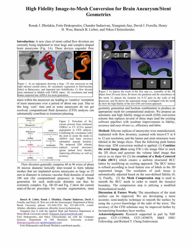
Figure 1. A) an angiogram showing a large ~25 mm aneurysm on the right internal carotid artery; B) vasculature segmented in SimVascular, lofted in Rhinoceros, and imported into SolidWorks; C) flow diverter stent simulated in Matlab with VMTK input; D) vasculature and stent bodies imported into ADINA for mesh generation. Introduction: A new class of stents called flow diverters are currently being implanted to treat large and complex-shaped brain aneurysms (Fig. 1A). These devices engender flow stasis within the aneurysm sac leading to ‘curative’ resorption of most aneurysms over a period of about one year. Due to this long ‘cure’ time and as some aneurysms do not get resolved, computational fluid dynamics (CFD) analysis can substantially contribute to treatment planning. Flow diverters generally comprise 48 to 96 wires of about 30 micron diameter helically inter-wound to form tubular meshes that are implanted across aneurysms as large as 25 mm in diameter in tortuous vascular fluid domains of around 100 mm (for computational purposes) in length. Mesh generation for such multi-scale domains can thus be extremely complex. Fig. 1B-1D and Fig. 2 show the current state-of-the-art procedure for vascular segmentation, stent Baruch B. Lieber, Ronak J. Dholakia, Chander Sadasivan, David J. Baruch B. Lieber, Ronak J. Dholakia, Chander Sadasivan, David J. Fiorella, and Henry H. Woo are with the Neurosurgery Department at Stony Brook University (phone: 631.444.1278; fax: 631.444.1535; e-mail: {blieber, rdholakia, csadasivan, dfiorella, hwoo}@sbumed.org. Xiangmin Jiao is with the Applied Math and Statistics Department at Stony Brook University (email: [email protected]) Fotis Drakopoulos, and Nikos Chrisochoides are with the Computer Sciences Department of Old Dominion University (e-mails: [email protected]; [email protected]). Fotis Drakopoulos and Ronak Dholakia contributed equally. geometry generation and boolean combination to produce an appropriate mesh for computational analysis. We propose an automatic and high fidelity image-to-mesh (I2M) conversion scheme that replaces several of these steps (and the existing software pipeline) with resultant improvements in fidelity, accuracy and easy-of-use i.e., efficiency and labor. Method: Silicone replicas of aneurysms were manufactured, implanted with flow diverters, scanned with micro-CT at 8 to 12 μm resolution, and the lumen and stent structures were labeled in the image slices. Then the following push button three-step I2M conversion method is applied: (1) Combine the axial image slices using ITK’s tile image filter to stack the 2D slices and generate the volume label image that serves as an input for (2) the creation of a Body-Centered Cubic (BCC) which creates a uniform structured BCC lattice by modifying an existing approach. The BCC lattice is refined according to local feature size of labels in the 3D segmented image. The resolution of each tissue is automatically adjusted based on the user-defined fidelity (0, 1]. Finally, (3) the Mesh Compression step is used to smooth the BCC mesh in order to match the tissue(s) boundary. The compression step is utilizing a modified biomechanical model. Discussion & Future Work: The smoothness of the stent surface can be improved. We are developing a more accurate, semi-analytic technique to smooth the surface by using the a priori knowledge of the radii of the wires. The accuracy of the CFD solutions may be improved further by incorporating boundary layer meshes. Acknowledgments: Research supported in part by NSF grants: CCF-1139864, CCF-1439079, M&S ODU Fellowship, and Richard T. Cheng Endowment. High Fidelity Image-to-Mesh Conversion for Brain Aneurysm/Stent Geometries Ronak J. Dholakia, Fotis Drakopoulos, Chander Sadasivan, Xiangmin Jiao, David J. Fiorella, Henry H. Woo, Baruch B. Lieber, and Nikos Chrisochoides Figure 3 A) depicts the result of the first step i.e., assembly of the 3D object from 2D axial slices, B) shows the gradation and the smoothness of the mesh, C) depicts the footprint (in 8-12 μm) on the walls of the aneurysm, and D) shows the segmented image overlapped with the mesh to show the high fidelity of the new I2M conversion approach. Figure 2. Flowchart of the current process from rotational (3DRA) or CT (CTA) patient angiograms to CFD analysis. Combining the vasculature with the stent to create the mesh in ADINA (red font) involves substantial manual iteration. The proposed I2M scheme replaces several processes (green dashed box) thereby improving efficiency as well as accuracy.