+ All Categories
Home > Documents > TO of this technical documentary report does not constitute Air F9rce ... of input device...

TO of this technical documentary report does not constitute Air F9rce ... of input device...

Date post: 08-Mar-2018
Category:
Upload: doanhanh
View: 218 times
Download: 2 times
Share this document with a friend
274
UNCLASSIFIED AD NUMBER AD419254 NEW LIMITATION CHANGE TO Approved for public release, distribution unlimited FROM Distribution authorized to U.S. Gov't. agencies only; Administrative/Operational Use; SEP 1963. Other requests shall be referred to Electronic Systems Division, ATTN: ESAT, Hanscom AFB, MA 01731-5000. AUTHORITY ESD ltr dtd 15 May 1968 THIS PAGE IS UNCLASSIFIED
Transcript

UNCLASSIFIED

AD NUMBER

AD419254

NEW LIMITATION CHANGE

TOApproved for public release, distributionunlimited

FROMDistribution authorized to U.S. Gov't.agencies only; Administrative/OperationalUse; SEP 1963. Other requests shall bereferred to Electronic Systems Division,ATTN: ESAT, Hanscom AFB, MA 01731-5000.

AUTHORITY

ESD ltr dtd 15 May 1968

THIS PAGE IS UNCLASSIFIED

I ESD-I*DR-63-545

I"'J

U STUDY OF COMPUTERMANUAL INPUT DEVICES

1214 TECHNICAL DOCUMENTARY REPORT NO. ESD-TDR-63-545

SEPTEMBER 1963

William 1'. PollockL-Gilbert a Gildner

DECISION SCIENCES LABORATORYELECTRONIC SYSTEMS DIVISION

C) AIR FORCE SYSTEMS COMMAND

UNITED STATES AIR FORCE[ L.G.Hanscom Field, Bedford, Massachusetts

[ II

, ;Project 9678, Task 967801

(Prepared Under Contract No. AF19(628)-435, By Bendix Systems Division AnoArbor, Michigun)

I

I.EGA1. NOTICE

This report was prepared and delivered to the Department of the Air Force as an account

of Government-sponsored work. It summarizes and comments on characteristics determined

by test or evaluation of samples of various products with respect to performance under

assumed conditions. Conditions relating to the manufacture and selection of test samples

were not urder Bendix control, anti no in.erence is intended with respect to (i) performance

of the test samples; under other conditions; or (ii) performance of other samples under the

same conditions.

When U.S. Government drawings, specifications or other data are used for any purpose

other than a definitely related government procurement operation, the government thereby

incurs no resplnsibility nor any obligation whatsoever; and the fact that the government

may have formulated, furnished, or in any way supplied the said drawings, specifications,

or other data is not to be regarded by implication or otherwise, as in any manner licens-

ing the holder or any other person or conveying any rights or permission to manufacture,

use, or sell any patented invention that may in any way be related thereto.

This document may be reproduced to satisfy official needs of U.S. Government agencies.

No other reproduction is authorized exccpt with permission of Hq Electronic Systems Divi-

sion, Attn: ESAT, .. G. lianscom Field, Bedford, Massachusetts.

)o not return this cory. Retain or destroy.

U.S. Government agencies may obtain copies of this report directly from the Defense

Documentation Center (DDC). Other qwilified DI)DC users should request through Ilq Elec-

tronic Systems Division, Attn: ESAT, .. G. lanscom Field. Bedford, Massachusetts.

DI)( release to the Office of Technical Services is not authorized.

I

I

PThe guidance and assistance offered throughout the study by the con-

I tract monitor, Mr. James D. Baker, and the frequent constructive criticism

offered by Dr. Walter E. Organist are gratefully acknowledged.

This report has been assigned Bendix Systems Division Report No.

f7BSC 40138.

{i

FIi

ESD-TDR-63-545

I STUDY OF COM'.PUTER MANUAL INPUT DEVICES

[ABSTRACTA study of computer manual input devices and their associated human engineering

characteristics was conducted for the purpose of developinq a scheme for relating

these devices to operator performance characteristics, computer characteristics and

s, stem requirements. Conventional commercially available input devices such as

pushbuttons, togqle switches, joysticks, etc. wee surveyed. Available literature

pertaining to human performance with such devices was reviewed and summarized.

The suitability of devices and availability rf applicable performance data are

related to a generalized operator task tamily by a set of tables. Results of the

study show a wide variety of available devices, inadequate research data establish-

ing performance for various devices and device characteristics, and incomplete

specification of operator input tasks in existing systems. Specific recommendations

are mode for additional research to correct these deficiencies and to nulde applied

research on developmental input devices such as speech recognizers. Results of

an experiment studying the speed and accuracy of subjezts' responses as a function

of the number of response alternatives and type of response mechanism (input

device) are included.

REVIEW AND APPROVAL

Publication of this technical documentary report does not constitute Air F9rceapproval of the report's findinrjs or conclusions. It is published only for theexchange and stimulation of ideas.

,W LTER E. ORGANIST ANT)NY DEBONS, Col, USAFCief, Operator Performance Division 'r- trectrDecision Siences Laboratory Decision Sciences Laboratory

ii,

I

TABLE OF CONTENTS

Page

TABLE OF CONTENTS v

LIST OF TABLES vii

LIST OF ILLUSTRATIONS ix

1. INTRODUCTION 1-1

2. OPERATOR INPUT TASKS 2-1

3. DEVICE SURVEY 3-1

4. LITERATURE SURVEY: DEVICE/TASK PERFORMANCEDATA 4- 1

5. TASK/DEVICE/PERFORMANCE DATA COMPILATION 5-1

6. EXPERIMENTAL RESULTS 6-1

7. DEVELOPMENTAL DEVICES 7-I

8. CONCLUSIONS 8-1

9. RECOMMENDATIONS 9-1

APPENDIX I DEVICE SURVEY DATA SUMMARY 1-1

APPENDIX II BIBLIOGRAPHY REFERENCES ANDSUMMARIES II-i

APPENDIX III EXPERIMENT ON HUMAN PERFORMANCEWITH SEVERAL DEVICE TYPES AND NUM-

BER OF RESPONSE ALTERNATIVES 111-1

v

LIST OF TABLES

Table Title Page

2-1 Manual Input Tasks 2-43-1 Summary of Input Device Survey 3-35-1 Task Device Pairing: Summary 5-35-2 Task Device Pairing: Toggle Switches 5-65-3 Task Device Pairing: Lever Switches 5-75-4 Task Device Pairing: Slide Switches 5-85-5 Task Device Pairing: Rocker Switches 5-95-6 Task Device Pairing: Pushbutton Switches 5-105-7 Task Device Pairing: Rotary Switches 5-111 5-8 Task Device Pairing: Thumbwheel 5-125-9 Task Device Pairing: Keyboards 5-135-10 Task Device Pairing: 2-Dimensional Controls 5-145-11 Input Device Design Characteristics 5-15I1-I Response Time Data (Seconds) 111-8111-2 Response Time Analysis 111-9111-3 Response Time Variability - Standard Deviations

(Seconds) III- 10111-4 Error Data 111-13

Iv

LVi

I

ILIST OF ILLUSTRATIONS

Figure Title Page

3-1 Typical Switch Force/Displacement Diagrams 3-93-2 Typical Switch Force/Displacement Diagram 3-103-3 Typical Switch Force/Displacement Diagrams 3-11

1 3-4 Typical Switch Force/Displacement Diagrams 2-123-5 Typical Switch Force/Displacement Diagrams 3-133-6 Typical Switch Force/Displacement Diagrams 3-14111- 1 Subject Station 111-3111-2 Switches Tested 111-3111-3 Mean Response Time 111-7111-4 Performance Variability III- 12111-5 Combined Performance - Estimated Equivocation III-17111-6 Combined Performance - Percent Transmitted 111-18111-7 Combined Performance - Percent Transmitted

(P 2 H in. ) 111-19" 111-8 Maximum Information Transmission 111-20

111-9 Effects of Error on Estimates of InformationTransmission [11-22

III-10 Corrected Response Time 1/P 111-24111- 11 Corrected Response Time 1/P 2 111-25H.n

III-12 Corrected Response Time T in 111-26I

(i1ot

I

SECTION 1

INTRODUCTION

With the rapid advances in engineering and scientific technologies

made in the past two decades, systems for surveillance, threat evaluation,

weapon control, and command control have reached a degree of complexity

that makes it necessary for more and more of the system functions, tra-

ditionally assigned for human performance, to be assumed by machines.

In the majority of such cases, these changes are justifiably based on

the superiority of modern machines with respect to the speed and accuracy

with which functions of a quantitative nature can be performed. This trend

toward function mechanization has not, however, relegated man to an in-

significant or subservient role in systems operations. Rather, the mech-

anization trend has served to release man from routine, repetitive system

tasks, making him more available for exercise of his unique intelligence

capabilities in directing machine operations, and in augmenting automatic

equipment inthe handling of improbable events and the making of decisions involv-

[ing currently non-quantifiable rules. Inmost instances, this executive role for

humans is performed in semi-detachment from the system for which he is

[ providing executive direction. His interaction with other syste - elements

and the system environment is mediated by a computer which, on the one hand,

processes, transduces, amplifies and disseminates the humans' actions to

effect the desired system response, and on the other hand provides the human

operator with data on system status and conditions of the system environ-

ment. In this concept of complementary functions of man and computer,

1-1

Ithe critical feature affecting the individual and the combined functions of

the two system elements is the adequacy of the communications link be- Itween the two. Unless the computer output devices present the system -1

data in a form readily assimilable by the human senses, some portions of

that data will either not be available for use by man or will be incorrectly

received and thus constitute a source of system error. Similarly. devices

provided for man informing the computer of his desires for a change in

*1system status must be matched to the motor characteristics of the human.

Mis-match must lead to loss of time by the system and to incorrect com-

mands being received by the computer, resulting in system error. Thus,-J

effective design of a man/computer interface to meet particular system re-

quirements is dependent on knowledge of man's sensory and motor capa-

bilities in using devices with various differing physical characteristics to

communicate with computers whose characteristics may also vary.

The stud), described in the report that follows was focused on the

operator input side of this man/computer communication system. Speci-

fically, the study was initiated to perform three ge-neral tasks:

I. Conduct of a systematic survey of the human engineering

characteristics of operator input devices used (or being

developed for use) in communicating (on-line and off-line,

with emphasis on on-line) with digital computers in informa-

tion processing systems for real-time operational problems.

2. Summarize available experimental data which may be used to

predict operator performance with the various combinations

1-2 1

of input device characteristics, digital computer characteris-

tics, and operator task characteristics dictated by system re-

quirements.

3. Where experimental data are not available for task 2, initiate

the experimental program required to provide the needed data.

Performance of these three general tasks was intended primarily to

provide a source of data for man/computer interface designers for their

use in selecting a device to implement a manual input function with the

selection conditioned by system requirements; i. e., operator task re-

quirements, and device availability. The approach to performance of the

study tasks was: 1) to survey existing and developmental command and

control systems in order to discover the family of inputing tasks assigned

to operators, with the tasks expressed in terms specific enough to permit

matching with input devices; 2) to survey appropriate sources to discover

the family of devices available and physically suitable for use in manual

inputing; 3) to survey the literature on human performance to discover

those data applicable to describing performance as a function of input task

and input device; and 4) to conduct experiments on task/device combina-

tions for which available data are lacking or inadequate.

The first three sections that follow summarize the procedure. prob-

lems and results from each of the efforts of operator task survey, input

device survey, and human performance data survey. Following those

sections is the summary of available data relating operator performance

with the various task/devica combinations, followed by a section that describes

1-3

Ithe experimental itudy completed and discusses the general experimental

problems in this man/computer interface area. The final sections of this Imain body of the report summarizes the conclusions of this study effort, iand recommends directions for further work. Appendices have been

attached for reporting details on available devices, references to avail-

able research reports pertinent to manual inputing and the technical de-

tails of the experimental phase of the program being reported.

-f

1-4

SEGTION 2

OPERATOR INPUT TASKS

The initial effort in this area was to review available information on

existing and developmental command and control systems, specifically Air

Force L-systems. in order to discover the variety of input tasks required

of system operators. In describing these input tasks, two ground rules

were accepted: I) the task descriptions should be sufficiently specific. but

at the same time generally stated, so that major segments of a given L-

system operator's job could be described by selecting appropriate com-

binations of the individual inputing task descriptions and 2) the descriptions

should be phrased such that selection of an input device to implement the

task would not require major re-definition to reflect required input device

functional characteristics. The first ground rule is an attempt to get away

r from over- specification of tasks, over- specification that would uniquely

label a task to a particular L-system application. For example, an oper-

ator in 416-L has the task of inputing instructions to the computer to attach

[a label of "unknown". "hostile" or "friendly" to a track. Similarly, an

operator in 473-L has the task of inputing instructions to the computer to

f provide symbolic, graphic or pictoria. display of a particular data category.

The common feature to these two specific tasks is that the operator in each

case is inputing to the computer an indication of his selection of one of

three alternatives. An attempt has been made to reduce all those discov-

ered L-system input tasks to such generalized statements.

ii 2-I

The second ground rule stated above was adopted to assure a rel-

atively ready comparability of tasks and devices, given the functional char-

acteristics of the devices. Again, the primary intent of the study was to

provide data permitting determination of probable operator performance

using a specific input device to perform a given inputing task. With that

orientation, it is necessary to describe the task in terms which reflect

both the system functional requirements of the task and the functional char-

acteristics of devices available for implem,nting the task. As it turned

out, meeting this ground rule becomes nearly automatic in describing the

tasks to meet the first ground rule described above; i. e. . the exercise to

reduce the tasks to what is felt to be the required level of specificity re-

suits in tasks relatable to some human motor output requirement, which is

in turn readily comparable to device characteristics. The systems chosen

for intensive review as functionally representative of the large number of

L-systems in various states of operation and development wero 416-L

(SAGE), 425-L (NORAD Combat Operations Center), and 473-L (Hq USAF

Command and Control System). A review of data available on these systems

showed that the necessary data on manual input tasks does not exist in suf-

ficient conciseness or detail to fully meet the requirements of this study.

Even with the large volume of documentation for SAGE, it is frequently

necessary to infer an input task from some provided hardware capability.

Similarly, the suggested design for the 473-L Integrated Console may be

used to infer the variety of input tasks that an operator could perform. *

See Tech. Note #1 to MIL-1-27114 (USAF), Human Engineering Considera-

tions for Integrated Console Design (part of 473-L Design Specification).

2-2

Data for these systems, however, on the specific tasks that the operators

[ are required by system design to perform have not been found. Thus, the

- tasks that have been isolated reflect an admixture of tasks based on rel-

atively firm information from L-system literature, on inferences from

L-system hardware characteristics and on inferences based on various bits

and pieces of information on man's general role in digital computer-

containing command and control systems. *

The task descriptions that have resulted are given in Table 2-I along

with specific examples of each of the generalized tasks. The order of list-

ing of the tasks generally reflects increasing task complexity from top to

bottom. Similarly, moving from top to bottom, the options associated with

V a task increase, reflecting a greater flexibility, or lesser predictability of

a task outcome. One of the quite obvious characteristics of the man-

computer communication situation provided in L-systems'is the limited-

choice, or, in the case of input devices, limited response options, per-

mitted the human. It is an open question whether this pre-programmed

response constraint is merely a reflection on limitations of computer tech-

[nology or if this is a deliberate system design concept to constrain system

operators to a specific, limited set of input-output relations.

One other comment on the tasks listed in Table 2-1 is appropriate.

While the task, "Indicate selection of I of n alternatives" would be adequate

to cover those tasks preceding it in the list. the listing of those tasks

See, for example, Display Problems in Aerospace Surveillance Systems

AFESD-TDR-61-32, June 1961, prepared under Contract No. AFI9(604)-

7366, W0 October 1961, HRB-Singer, Inc.

2-3

Iinvolving the selection of I of 2-6 alternatives has been included as a con-

venience to facilitate device/task comparison discussed in Section 5. 1Again, those tasks listed in Table 2-1 are reFresentative of L-

system operator input tasks. A considerably larger study in depth than

that permitted by the scope of this study is required for a completely de-

finitive role of the man-to-computer communications picture in L-systems

across the board.

TABLE 2-1

MANUAL INPUT TASKS "

Task Example

Indicate selection of: iiI of 2 alternatives - Power on/off selection entryI of 3 alternatives - Display scale selection entryI of 4 alternatives - Weapon-type selection entryI of 5 alternatives - Message format selection entryI of 6 alternatives - DEFCON selection entryI of n alternatives - Preprogrammed data processing

function selection entry

Decimal digit (0-9) - Track age entryDecimal number (> 9) - Track altitude (uncoded) entry

Octal digit (0-7) - Request octal-coded file contentOctal number ( > 7) - Request octal-coded file content

Adjust magnitude - Set sensor pointing angle

Designate location on 2-dimen.. Designate a specific tracksurfaceSelect alpha-numeric Assign a track numbercombinationCompose limited-vocabulary Data request through Query languagealpha-numeric messageCompose unlimited-vocabulary Enter intelligence summaryalpha-numeric message

2-4

SECTION 3

DEVICE SURVEY

[- The detailed devices survey has been made in order to determine the

[ functional and human engineering characteristics of available devices suit-

able for computer manual input. From the beginning it was recognized

that this survey should be a sampling of the spectrum of devices rather

than an exhaustive catalog of all manufacturers' products. This is a neces-

sary and practical approach as mary manufacturers offer design variations

numbering in the hundreds, and some in the thousands. It was also con-

sidered necessary to limit the scope of devices to be considered to those

that might reasonably be considered for use in a military command and

control system. Thus. heavy-duty industrial, electrical applicance. and

"economy grade" devices have been generally excluded. Further, devices

were considered on the component level. excluding complet, input-output

consoles and special purpose combinations of devices.

[ The survey was initiated with general inquiry letters to companies

listed under applicable device categories in purchasing indices and not

already represented in Bendix Systems Division files. A review of avail-

[able manufacturers' literature was then made to determine what informa-

K tion was lacking, and to devise a means for summarizing the pertinent data.

Additional letters were then sent to most device manufacturers requesting

specific data not given in their standard literature. This letter usually

included a request for force-displacement details. The quality of repliesI,-

ranged from excellent to no reply at all in spite of follow-up letters. While

3-1

I

some additional information might have been obtained through continued

effort the situation seemed to have reached the point of diminishing returns.

If parametric studies are ever made on specific classes of devices, some

further contact with manufacturers might be worthwhile.

A total of 157 companies were contacted in the device survey.

Of this number, 95 have items listed in the device survey. The remainder

either did not respond or did not have a device of interest.

Device characteristics have been summarized by transferring per-

tinent information from each manufacturer's literature to data summary

sheets. The completed summary sheets are attached as Appendix I. An

attempt was made to select representative samples of each manufacturer's

line on the basis of differing human engineering characteristics. Devices

were selected, where possible, with sufficient electrical poles to permit

binary encoding of each switch position. Variations of devices to withstand

extreme environments or switches including safety locks were not con-

sidered. To illustrate the large variety of available devices, a summary

of the number of devices and manufacturers listed in the survey is given in

Table 3- I.

Many of the devices listed, mainly rotary switches and shaft encoders,

are not complete manual input devices. They must be provided with at

least a knob of some sort and usually a calibrated dial or remote indicator

as well. Occasionally, more complex assemblies may be incorporated in-

volving gears, clutches, etc. These components have not been surveyed.

They, along with other details, must be considered in specific design

3-2

TABLE 3.1

SUMMARY OF INPUT DEVICE SURVEY

Device Category No. of Items No. of Manufacturers

Toggle Switches 62 17

Lever Switches 42 11

Slide Switches 8 5

Rocker Switches i5 6

Rotary Switches 99 26

Thumbwheel Switches 18 8

Pushbuttons, unilluminated 75 25

Pushbuttons, illuminated 147 31

Keyboards 39 18

Shaft Encoders 48 9

Joysticks 6 4

applications but they probably do not exert a primary influence on selection

of the basic manual input mechanism.

Some confusion is apt to exist with regard to the classification of de-

vices. For the most part devices have been classified according to the

class names given by the manufacturers. However, areas of confusion

may exist between toggles and levers, between levers and slides, and be-

tween pushbutton arrays and keyboards. Actually, confusion is more likely

to exist when dealing with definitions of the clarises or with the summary

data than when comparing two physical devices side-by-side. Without at-

tempting rigid, mutually exclusive definitions, a few general contrasting

characteristics may be listed.

3-3

Toggle Lever I

Snap action electrical contacts Leaf or wafer electrical contacts IMetal handle, usually bat shape Plastic handle, variety of shapes

Distinct snap feel and audible

click for maintained action 1Lever Slide IIVariable orientation Fixed orientation, usually 900,

between handle and between handle and mounting surface 7I

mounting surface 1

Pushbutton Array Keyboard-!

Operation by index finger Configuration and operating force .

usually intended permits rapid sequential operation

Custom design using several fingers. Fixed design

available as off-the-shelf unit

Some mention should be made of types of devices not represented

in the summary sheets of Appendix 1. The most notable omission is a

complete summary of two-dimensional controllers. This class of input

device includes pantographs, joysticks, rolling balls, light guns and pen-

cils, and voltage probe pencils with conducting glass overlays. Of these,

only joysticks are known to be commercially available and then usually

witis an analog rather than digital output. One exception to this is a light!

pencil available from Digital Equipment Corporation. When other types of =

two-dimensional controllers are in use they are usually specially designed

items. Descriptions of the design and operation of these various two-

dimensional controllers may be found in the literature.

3-4

Other devices not included in the current device survey are telephone

dials, and touch pushbuttons. Two companies with telephone dial devices

were located, but neither replied to requests for additional information.

One of the devices was a small, hand-held data recorder with telephone

dial input. It could be considered an off-line input device. Touch opera-

ted pushbuttons are occasionally used in elevator control systems. In ad-

dition, two companies were heard to be developing touch pushbuttons for

possible commercial sales. Again. no replies were received to requests

for information. One company, Tung Sol, has recently announced a small

electronic switch that can be operated by touching its input leads antennae.

These leads could be connected to metal plates for a touch operated push-

V" button.

All devices mentioned thus far require gross human motor action,

predominantly manual, for their operation. More advanced techniques in-

V volving automatic speech recognition, eye position monitoring, neurological

sensing, and hand writing readers are in various stages of development.

Considerable research has been accomplished over the last few years

[ toward development of an automatic speech recognition capability. Suf-

ficient progress has been made that practical use could soon he made of

devices capable of recognizing on the order of IS words, the ten digits plus

a few command words. Two organizations have announced development of

devices with this capability, IBM Advanced Systems Development Division

Lab. and Case Institute of Technology. In addition, Voice Systems, Inc. of

Campbell, California,has announced that they are marketing a speech-operated

3-5

switch designed for control of light machinery and are studying possible

voice-operated cash registers and mail sorting systems.

Another advanced inputing technique that might be considered in the

near future for computer manual input is automatic reading of handwriting,

or at least of hand printed characters. Developments in this area have also

progressed to the point where practical applications can start to be con-

sidered. For example, IBM Advanced Systems Development Division has

developed a devj e capabie of reading a variety of styles of hand printed

digits. Testi of this device conducted at Tufts University have produced

correct readings 98. 5% of the time. Also, Bell Telephone Labs have a de-

vice which recognizes whole words, from a limited vocabulary, when writ-

ten in cursive script on a special conductive writing surface.

Current state-of-the-art in both speech and handwriting recognition

is best obtained through a review of the literature. Research on other

forms of advanced inputing techniques has not advanced to the point where

their utilization can be forecast.

Two general conclusions can be drawn from the device survey; there

is a wide variety of devices from which to choose and incomplete human

engineering data are available for most of these devices. The main data

deficiency is associated with specifications of dynamic operating charac-

teristics; i. e., operating force and displacement. Of these, displacement

data are more complete than operating force data. Quantitative data re-

lating these two parameters are almost completely lacking; however, it is

the relation between these two parameters that determines the characteristic

3-6

"feel" of a device. Manufacturers specify this relation in qualitative terms

[such as "snap action," positive action, " "no snap action, ' or "light touch.

The lack of quantitative data in this area suggests no populai demand and

perhaps no major performance difference associated with different force/

[displacement relations. One notable exception is an experiment by Grisez,

a summary of which has been reported by Chapanis . This experiment shows

that operating force is inversely related to several operator parameters in

pushbutton operation, but that displacement as a variable has negligible effects.

Another possible reason for the lack of force/displacement character-

istics is the difficulty of obtaining them. Existing instruments suitable for

this task are in the family of spring testers and are generally designed to mea-

sure linear tension or compression and associated displacement. These de-

vices are reasonably well suited to measurement of pushbutton characteris-

tics but are not well suited to measurement of angular displacement devices

V such as rotary switches, toggles, rockers, and thumbwheels. Assemblyof

special purpose fixtures to accommodate these latter devices presents no

I. technological problem but was beyond the scope of the present study.[ . _ __

Chapanis, A. "Engineering Psychology, " Annual Review of Psychology.

14, 1963. (See p. 295 for summary of: Grisez, J. Etude comparative

L de boutons poussiors selon differents modes d'utilisation et en function

de leurs caracteristiques de pression et de course. Bull. Centre Etudes

et Recherche Psychotechniques, 8, 1959, pp. 149-156.)

3-7

Several pushbutton force/displacement characteristics were meas-

ured to illustrate the different characteristics that exist and to discover

whatever practical problems might exist in obtaining these measurements.

Figures 3- 1 through 3-6 show sample characteristics of three types of

pushbutton switch actiors. momentary non-snap, momentary snap. and

alternate action.

The operate stroke characteristic is produced during the inward push

on the button and the release characteristic on the outward movement, when

the finger is removed. The negative slope "transition" portion of some

characteristics is typical of snap action switches and is associated with

the over-center mechanism within the switch. These force/displacement

curves shown here serve to illustrate why switches with similar operating

forces and similar displacements may "feel" different. Whether or not

this "feel" characteristic is an important operator performance influencing

parameter is as yet an unanswered question.

These curves represent static characteristics in that the switch was

stationary during the reading of each data point. Therefore the effects of

kinetic friction, viscous damping, and inertia on dynamic operation are no,

included. Design of discrete position switches, however, indicates that

these parameters would be minor in comparison to the primary effects of

elastic resistance and static friction. Data points were measured with a

Chatillon Model LTC-5 Tension and Compression Tester modified with a

more accurate displacement scale and improved pointer. The scale used

was divided into 0. 01 inch steps and, with interpolation, readings at

0. 005" intervals could be taken. jiowever, maintaining comparable

3-8

I RAYHILL 4002FORCE(MOMENTARY NON-SNAP)

(LSS) _ _ _ _ _ _

OPEAT STROKE__RELEASE

X POINTS OF ELECTRICAL TRANSITION

0.1 0.2DISPLACEMENT-(I)

GRAYIIILL 35-1

FOR E(MOMENTARY NON-SNAP)

(LB 5)

X POINT OP ELECTRICAL TRANSIT ION

I'0 0.1 0.2DISPLACEMENT - (in.)

Figure 3-1 Typical Switch Force/ Displacement Diagrams

3-9

GRAYMIL

OPEATE SRLL

X(PONMSOFNEECTICA(SOT NA ATNIIO

FORCESLAEET in) 0. .

(LBS)-2Tpcl wthFoc/Dspae et iga

_________1OPRT0SRK

CONTkOL SWITCH F 112MS 25089-3CMOMIENTARY

(FIRM SNAP ACTION)

FOC(LOS)

2 OPERATE STROKERELEASE

. .. TRANSITIONX PONTSOF ELECTRICAL

TRNSIT ION

00.1 0.2[I DISPLACEMENT - (in.)

NILLISWITCH B-PD3-2MOMENTARYF (FIRM SNAP ACTION)

FORCEIi (LBS)

-OPERATE STROKE

----------------------------- TRANSITIONPOINTS OF ELECTRICALTRANSITION4

0 . 0.2DISPLACEMENT - (in.)

Figure 3- 3 Typical Switch Force/ Displacemen~t Diagrams

3-11

I ____ OPERATE STROKE0---RE LEASE

-- TRANSITION2

X POINTS OF ELECTRICAL

4

(LBS)E

K ORA Y(MOMENTARY SN AP ACTION)

@0 0.1 0.2DISPL. CEMENT-('.

6

-OPERATE STROKE

0'RE LEASE--- TRANSITION MASTER SPECIALITIES

X POINTS OF ELECTRICAL (MOMENTARY SNAP ACTION)TRANSIT ION

4

F ORCE(LSS)

0 0.1 0.2DISPLACEMENT-(I)

Figure 3-4 Typical Switch Force/ Displacement Diagram.3-12

I.r

LICON 16-404(ALTERNATE ACTION)

ACTUATE

FORCE(LOS)

-OPERATE STROKE

STRANSITIONXPOINTS OP ELECTRICAL

0 0.1 0.2DISPLACEMENT -(in.)

LICON 16-404(ALTERNATE ACTION)RELEASE 19

4

FOR CE(LSS)

-OPERATE STROKE

F 1 ~~~~TRANSITIONI v POINTS OF ELECTRICALI A TRANSITION

00.1 0.2I DISPLACEMENT - (in.)

Figure 3-5 Typical Switch Force/ Displacement Diagrams

611MASTER SPECIALITIES(ALTERNATE ACTION)

ACTUATE

I - OPERATE STROKE0--RELASE

---------TRANSITION

O.WP.011,X POINTS OF ELECTRICALTRANSIT ION

0 010.2DISPLACEMENT -(in.)

MASTER SPECIALTIES(ALTERNATE ACTION)RE LEASE

4

FORCE(LOS)

I - OPERATE STROKE

- -TRANSITION

XPOINTS OF ELECTRICAL

0 0.I20 0.10.

DISPLACEMENT -(in.)

3-14 Figure 3-6 Typical Switch Force/ Displacement Diagramsa

accuracy proved fo be both difficult and time consuming due primarily to the

f lack of rigidity in the fixture. Two modifications of the present apparatus

were thought of which should be considered if a more complete study is to

be made of force/diaplacement characteristics. At a minimum the instru-

tment should be equipped with a gear driven pointer permitting displacement

" measurement resolution and accuracy of about 0. 00" without the need of a

magnifying lens for reading tile scale. An even greater convenience would

result if both the displacement and force measuring elements of the fixture

were equipped with electrical data pickoffs. Linear differential trans-

formers would be well suited for this task since they would provide neg-

ligible mechanical loading. The electrical outputs could then be applied

to the X and Y inputs of an oscilloscope, through necessary demodulators.

to produce the characteristic curve directly on the scope face. Photo-

[I graphs could then be taken for permanent records thus eliminating the

[ need for manual data plotting. In addition, switches could be activated at

the normal rate of speed, thus producing true dynamic force/displacement

F. characteristics. Also, any future study of switch force/displacement char-

acteristics should give consideration to the difference between different

samples of the same model and even differences between operation cycles

of the same sample.

Another major data deficiency involves the luminance of lightedde-

vices, notably pushbuttons. This parameter is not completely under the

control of the device manufacturer, however. The lamp rating. number of

I lamps used, and lamp operating voltage are under the control of the user.

.

3-1 5

The manufacturer has direct control over the reflectance characteristics

of the lamp housing, the lamp type to be used, and the transinission char-

acteristics of the viewing screen. In spite of the complexity, a couple of

manufacturers can provide an extensive set of luminance data for various

combinations of viewing screens, number of lamps, and lamp voltage. For

large ucreen pushbuttons. luminance distribution is also of interest. Such

data are available from only one manufacturer.

3-16

SECTION 4

iLITERATURE SURVEY: DEVICE/TASK PERFORMANCE DATA

A literature survey was made to compilh operator performance data

related to manual input tasks and devices. This literature survey began with

a thorough title search and abstract screening in numerous bibliographic

sources. Selected items, with abstracts where available, were entered on

individual cards. Major bibliographic sources reviewed included the Tufts

University Human Engineering Bibliography series, ASTIA Technical Ab-

stract Bulletins, Psychological Abstracts, and the various specific-area

bibliographies produced by technical societies, for example, the Acoustical

Society of American and the Human Factors Society.

- The initial search used minimum-acceptance criteria. As a result

many items initially were collected which turned out to have little direct

bearing on the current study. This initial listing yielded over 590 entries

and required some topical classification. The first classification scheme

L tried was based upon the primary focus of the research being reported.

This scheme was later modified to contain categories pertaining to specific

devices. References are now arranged according to the type of input de-

[. vices studied or used in the reported research. Thus, all available

references bearing on the performance of a particular device can easily

be located.

Ii All reports reviewed and summarized present, to some extent, the

results of an objective, usually empirical, investigation. References

which only present "recommended" design values were not summarized

4-1

althoiugh they were screentcd for more basic references upon which the

recommendations were presumably bap-ed. The number of references

reviewed and summarized in the various topical categories is given be-

low.

No. of References

Category Total Reviewed Summarized

Toggle Switches 7 7

Lever Switches 2 2

Rocker Switches I I

Pushbuttons and Keysets 53 37

Rotary Controls 49 23

Thumbwheels 1 1

Two-Dimensional Controllers 34 10

Appendix I contains listings of all references considered together with

copies of all report summaries prepared. In addition, a few references

selected for review for which copies were not obtained are also included.

Report summaries have been prepared in tabular form with headings

for Task, Simulus, Subjects, Response Mechanism, Conditions, and Re-

sults. Only those aspects of a research report of direct interest have

been extracted and summarized. No attempt was made to prepare

complete annotated bibliographies. In some cases it has been necessary

to recast quantitative results to provide concise speed and accuracy data.

Usually this has involved computation of means. Whenever possible the

summaries state performance in terms of speed and accuracy. These two

measures more precisely define operator performance than a single

4-2

combined measure such as information transmission rate and therefore

have a greater range of utility. The problem, of course, is that at times

the device with better speed performance does not have the best: accuracy

performance and a decision regarding relative importance of the two meas-

ures must be made. It is felt that this decision is better left to the per-

son applying the performance data than to those providing it either in an

original experiment or in a compilation from several sources. (See Appen-

dix III for further discussion of combined performance measures.)

Many of the reports reviewed have not treated the response mech-

anism as an experimental variable. They have been concerned with such

things as stimulus- response compatibility, discrimination reaction time,

[ information transfer rate, setting cues, etc. It has been only by coinci-

dence that these studies provide any absolute performance data for tasks

"1 and input devices (response mechanisms) of interest. This diversity of

[. focus of attention in the various reports is accompanied also by consider-

able variation in such significant experimental variables as stimulus form

Ii and presentation, pacing, training, instructions, task details, and scoring

1 procedures. Thus, it can readily be seen why the studies are not compar-

able for the purpose of specifying performance characteristics for task/

device combinations.

[Ii[

~4-3

ISECTION 9

STASK/ DEVICE/PERFORMANCE DATA COMPILATION

[ This section reports the initial attempt to combine the individual re-

suits of the operator input task study, the devices survey, and the human

Iperformance data survey. This attempt has taken the form of two sequen-

tial steps: 1) with the family of inputing tasks given, the descriptions of

the specific devices is used to determine for each of the tasks the particu-

lar class(es) of device and the specific device(s) within the class(es) which

have the functional characteristics required to implement the task, and 2)

with the task/devices combinations formed, the conditions of the various

experimental studiei are used to indicate the pertinence of the performance

fdata to the specific task/device combination(s).

In comparing available device applicability for implementing a par-

ticular task, three types of implementation concept have been used. First,

[thise devices were identified that provide the required capability for im-

plementing particular tasks when used individually. The label given to this

concept of matching devices with tasks is "Physical Applicability - Individ-

ual Device". The second implementation concept involved a group of a given

type of device, but with the constraint that only one of the devices in the

group would be required for each unique performance of the task. This

I. concept is called "Grouped Individuals - Discrete Operations". Finally,

[ the third concept involves a group of a given type of device with the pro-

vision for operation of more than one device in the group for task perform-

II ance. This concept is labeled "Grouped Individuals - Coded Operation".

[1.5-1

With this 'oded operation, only device groups coded in a binary or decimal

manner have been considered. Other coding schemes are available, of

course, limited only by the ingenuity of the system designer, but the large

number of such possible codes makes their consideration in the prebent con-

text impractical.

One other constraint in task/device pairing has been applied. The

condition has been adopted that devices will be considered functionally suit-

able for a task only if the full capability of the device is required. For ex-

ample, a five-position toggle switch could be used to implement a task of

indicating selection of one of three alternatives, but a large residual capa-

bility of the device would be untapped. Therefore, the task/device pairs

of concern here are only those in which the full capability of the device is

required.

Table 5-1 is a general summary of the task/device pairing. As sug-

gested by the legend for the table, summary information is given on the

physical, or functional, suitability of each of the classes of input device to

meet the requirements of the various tasks. The indicated suitability is

based on there being one or more specific samples of the device available

and appropriate to the task under the suitability criteria given above. In

addition, an indication is given in Table 5-1 of the availability of human

performance data for the task/device pair. These data availability indi-

cations are quite general, and include reference to all pertinent data sources

as described in Section 3 and Appendix II. Thus, the data availability in-

dications reflect data ranging from quite marginal to directly pertinent.

5-2

[

[U

o 0

0 0 0g04 4

u Q Ol N D ~ 1 .0." .

J J

00 0 0.ooiiN N ol o I Iw

00

"

w)

050 a-

4z i T4w2

00~~ 00 0 0 4

t

-t 010

00 00 0 0ju -

* .*. -- -5-3

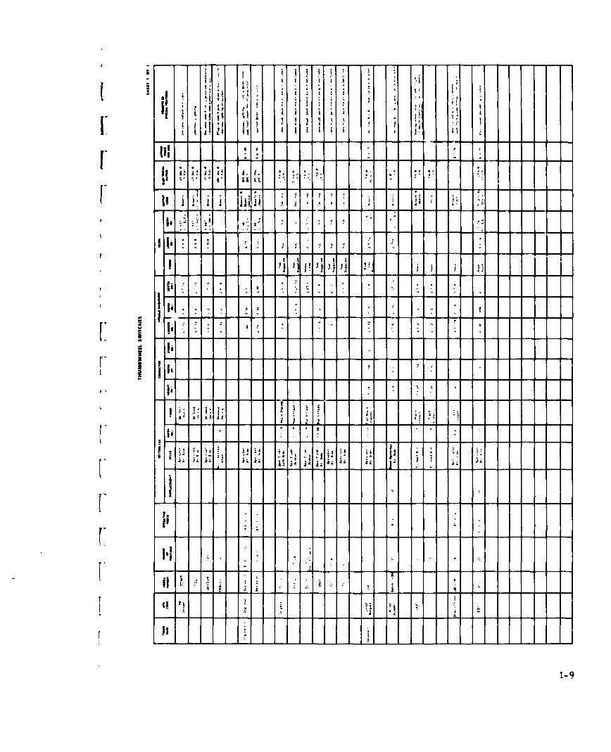
In Tables 5-2 through 5-J0, the functional characteristics of the spe-

cific device(s) of each class of device suitable for task implementation are

given. Each of the specific devices suggested is covered in the device sum-

mary sheets of Appendix I. In addition, each of the Tables contains indica-

tions of performance data availability for particular task/device pairs. Those

indications are given in the form of references to specific report summary

sheets in Appendix II. Note that some of the Tables contain references to

reports concerning a particular task, but with no implementing devices

,given. This ref1 ects a case in which the experimental use of a device

friled to coincide with the device/task pairing criteria given above.

The important message of Tables 5-1 through 5-10 is two fold: l)gen-

erally, there are several device options functionally suitable for implement-

ing each task and 2) there are relatively few performance-data-available

indications for the many task/device combinations listed. Even in those

cases where several references are noted it is usually impossible to find

sufficient comparable data to make a meaningful generalization.

In spite of the existence of a few pieces of appropriate data, the exist-

ence of several human engineering design standardb, and the current utili-

zation of a few highly popular types of computer input devices, this study

shows a gross lack of empirical evidence supporting the superiority of any

one of several devices that could be used to implement a given task.

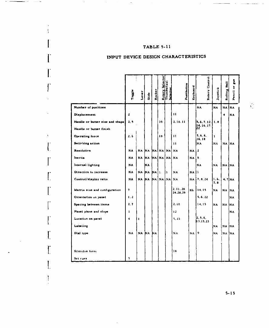
In addition to task and stimulus characteristics, numerous detailed

characteristics of the input device can conceivably influence an operator's

performance with the device. Table 5-11 shows which design characteristics

S-4

are likely to have some influence on an operator's performance using the

device. In addition, the table also indicates those summarized research

I - studies which treated a particular design parameter as a variable.

Many of the design characteristics cited cannot be specified by a sin-

gle numerical qUantity. For example, handle or button size is a three di-

" mensional quantity; switching action includes both descriptive and graphical

quantities, and internal lighting includes hue as well as intensity. The point

of this discussion is to illustrate that very little objective data exists de-

fining the desirable human engineering charact'.ristics of input devices and

furthermore that obtaining such data is a large complex task including con-

siderations of many parameters.

I5

1.

I S5-5

ulI

cnI

MI5

5 1 zq

a-a

-c. g. . I

.

u u-. o- V-

64 --

. - - - - - - - - ----- -

I'U

Ia - -- -- - - - - --

.'I II S.

-a-A1-ao 'U

Sa

a 1'Ia~

a ~"a 'U'I

- . .F 'U

F fl~ a- 'U N N -

S. ,

1.1 3 4 .J 4 4

U - -F ~'U'U* 80 Q e

- ~ - N SWI I I *0I - - - - - I--,

.; .; A -- -* - - - -

~5

C

a a; a a; a; aNW zw ~~ a2I-

* II II II II II -

U U 'U 'U 'U~: - - - - -k ~ - ~ ~j ~

t~ a a a a a * ~ I - 44 ~5' U w w ~ U ~ 4 ~; u;

I- ~ a a : -~~ a - - I344444 ~[ 'U N ~I * 4 3 3 3 ~ 2 4'- 2~

8-I B -I

U4 U4

1* - - - a - - - - - - -

5-7

Ma

a -

IUa ii

I

- 2:

w

aU

ma-aI- - -

j.4 a-4

U,r

~ 5 ma

U2 -, Ma

Ii*~

z

-a~-4 4~ ma

B

I *

~iIiIC C~r. M

:i ~ ~ C~

*! Nw NW!- ~ NWS

SII IS II II I

- * - * . - I,ma - - - S

k ~ ~ Z ma AN~ iii ~ ~ ~N ~aa a aI- a-

ma-U l.a.a .J -J - .a3 -4 4 4 i I ~ .a~ 'I

~ as 55 ~ I~ I~- - - - - -. - - - 4 C.'. U4 U4

5-a

IM

1...

W

w i

a

WIt

'9-

aall

U M

ItI

aa

so 9,21sa

vA ftn

U m -

F4 a

II-

Iw.. -

S---10

[I -

F 0

I-i

to 0

w 414ft..."J

a

4.1.

&0-4 -4 ft - - - - -

it

4.4

[[

- - -- - - -

aa

I. a - -- - - - -

U

U

I.'I a

a

a

C

U

F -

4 04 5 ~.- ~,- ijj-~~.iTS - -

U V

Ba w w ~ UI a a a a ~ a aa b

ai a a ii

,- ,. .. aV S S S S

S V b V V V45 ~JS

a 4V 45

SC

C~ C~ C~

u~IwIw!~W~I- - * - 5~ U

1*. ~. -

~ a

! ~ I-J I- *- *- ~- ~- I- C ~ I ~ 8W

4 J 4 -~ J .1 - * .. i~ PUEWIS

~ ~ ~ ~ w*~ 4 ~ 4 2 fl a '-~ ~ iz

W

I

n

0 w

o

1 u

NK

01

u WE

5-14

TABLE 5-11

[ INPUT DEVICE DESIGN CHARACTERISTICS

r iLA

Number of positions NA NA NA NA

Displacement ! ! 4 NA

Handle or butter size and shape 2,5 10 2.10.11 5.6.7,12., 1.814.16.17, 1

Handle or butter finish 22

Operating force 2.6 10 11 5,6.8. 116.18

Switchlng action I I NA NA NA NA

Resolutien NA NA NA NA NA NA NA NA 2

Inertia NA NA NA NA NA NA NA NA 5

Internal lighting NA NA NA NA NA NA

Direction to increase NA NA NA NA I I NA NA I

Control/display ratio NA NA NA NA NA NA NA NA 7,8.24 1,6, 4,7 NA7.8

Matrix size and configuration 7 2.11.20 K6 14,15 NA NA NA24.28,29

Orientation on panel I. 2 5.6,22 NA

Spacing between items 2,7 2. 0 14.15 NA NA NA

Panel plane and slope 1 1 2 NA

Location on panel 4 1, 23 2, 5.6.13,15.23

Labeling NA NA NA

IIDial type NA NA NA NA NA NA 9 NA NA NA

Stimulus formi 18

Set cues 3

5-15

SECTION 6

EXPERIMENTAL RESULTS

The previous section has shown a need for a large amount of addi-

tional experimental data before anything like a designer's handbook can be

assembled to aid in the selection of a particular device for a given manual

input task. The scope of this contract permitted a modest experi-

mental effort originally intended to test any hypothesis that might be de-

veloped. In view of the meager information in existence, it was found im-

possible to draw any conclusion regarding the superiority of one device over

another. Thus it was decided that better use could be made of the experi-

mental effort if it was devoted to collection of performance data for sev-

erai devices on some typical task. The task chosen was the selection of

[one of several sets of alternatives specifically I of 2, 4, 7 or 10 alterna-

[ tives. Devices studied were representative samples of the four basic types

of devices that could reasonably be used in a grouped-discrete manner to

I implement random selection of one of a set of choices, namely toggle,slide

rocker, and pushbutton switches. Neither rotary selector switches nor

thumbwheels were included because each is inherently designed for an or-

F dered sequence setting task. Random selection in a practical context would

[ typically require the actuation of an additional READ control after comple-

tion of the selection, thus making either of these devices obviously inferior

I insofar as speed of performance is concerned. More complicated device

J configurations such as a symbolic scope display of alternatives with cursor

selection or grouped-coded configurations were not studied due to limitations

6-1

in the scope of the effort that could be undertaken. The mode of stimulus

presentation was intentionally selected to provide less than optimum stimulus-

response compatibility in order to produce absolute performance results

closer to those that might be expected in a real situation. Spacial stimulus7

coding with the indicator adjacent to each corresponding switch would be

the most compatible and probably provide the best performance. Practical

systems, however, rarely have an operator behave as a simple automaton

in a choice selection task. On the other hand, the focus of attention for

this experirment was to be the type of response mechanism and number of

alternatives and not elements of decision making. Therefore, a somewhat

middle of the road choice was made and symbolic stimulus coding was used.

It was further decided that the set of symbols used should be familiar to the

subject and from an ordered sequence, i. e. , the alphabet. A detailed de-

scription of this experiment and results obtained are contained in Appen-

dix III. In summary, the experiment showed statistically significant dif-

ference due to devices, alternatives, and subjects. None of the interactions

was significant. The results of this experiment were used as a vehicle

to explore the effect of several methods of combining speed and accuracy

data into a single performance score. The results of this effort are also

contained in Appendix III.

The experiment conducted under this contract effort is but one of

many which could and should be conducted to provide data for more ob-

jective selection of computer input devices in military systems.

6-2

SECTION 7

DEVELOPMENTAL DEVICES

Ii While the study effort was focused primarily on conventional com-

I mercially available devices, a few developmental devices and proposed

techniques deserve some discussion.

Three references (see Appendix II, reference summaries Keyboard

4, 5, and 6) pertaining to improved typewriter keyboards were located and

reviewed. Two of these present a convincing argument for improved speed

performance if the keyboard is rearranged to minimize the sequential use

of the same finger and hand. At least three different keyboard designs

have been proposed. All are based upon statistical information regarding

the frequency of ocrurrence of letters and letter pairs in the language. The{ third reference in this group reported the results of an extensive compara-

tive study of one of these revised keyboards, the D-orak-Dealey, and the

standard keyboard. Results showed no important difference between the

Itwo keyboards after several months of practice. From this it is concluded

Ithat any advantages of the "rythmic" keyboards are likely to be Cf margin-

al practical significance and that further research along this line would

I have low potential payoff for military systems.

[ There is some evidence that greatly improved speed performance

could be obtained in entering limited and unlimited vocabulary messages

via multiple-press keyboards. Multiple-press keyboards are devices which

I require the simultaneous pressing of two or more keys, The only knowni

commercially available device of this type is the Stoanotype machine used

7-1

by stenographers for machine shorthand. In typical use, these are generfl

purpose machines in that they can be used to record unrestricted messages,

including punctuation, in a quasi-phonetic code. No experiments studying

the speed and accuracy of Stenotype machines were found but manufacturers'

literature indicates that after training operators are capable of writing

150 or more words a minute.

Multiple press keyboards which have been studied experimentally have

used from 4 to 10 keys with each key ascigned to a particular finger of a

particular hand. The keys have usually been conveniently located under the

assigned finger with the hand held in a natural position. Several references

pertaining to this type of keyboard were located and summarized. Some

of these (Appendix 11, PB 5-8. 14. and 2S) were concerned with discrimina-

tion reaction time and used a spatial stimulus. Others (Appendix II, PB 28

and 29) studied the use of a four key keyboard for numerical data entry in

binary code. In one study of direct practical significance (Appendix II

PB 16) three subjects typed whole words, with a single press pattern, from

a vocabulary of 100 words at an average rate of 42 wpm. While the rate

obtained after modest practice was not superior to conventional typing

performance it was comparable. Whether or not additional practice would

result in significant improvement is an open question. A discrimination

reaction study (spatial stimulus) (Appendix I, PB 14) using 10 keys and

10 i alternatives achieved rates of about 1I50 patterns per minute,

Other examples (f practical use of multiple-press keyboards for data

entry are the U. S. and Canadian mail sorting systems. Although occasional

7-2

mention of these systems was noted during the study, no specific report

references were found.

[i Even if multiple press keyboards would not yield significantly greater

speed, they still may be desirable as computer input devices since they

I would permit simpler computer programs for input processing. Also,

less memory would be required to store whole-word codes than to store

a series of alphabetic code groups.

The information acquired during this study suggests that multiple-

press keyboards should receive greater attention as computer manual in-

put devices. In particular, increased operator input spetd and simplicity

of input processing programs would appear to result if multiple press key-

(" boards were used in place of conventional typewriters for limited vocabulary

message entry tasks. These advantages would be gained at the expense,

however, c ' increased operator training and the inability of untrained op-

erators to operate the device in an emergency.

Additional research is required to establish probable training tinses

and typical speed and accuracy data for trained and untrained operators

{ for a variety of input tasks. Also, both the Stenotype keyboard and one

key per finger configuration should be studied. It would be of interest to

learn why considerably faster performance is achieved on the seemingly

I more difficult Stenotype keyboard than on the 8 or 10 key hand configured

Il keyboards.

An input technique which has been suggested but not studied is the

I. use of a two-dimensional controller and a CRT display for alternative se-

7i 7-3

lection. The alternatives would be displayed on the CRT in word or sym-

bolic form. The operator would designate his selection by "tagging" the

selected alternative with his controller, joystick, light pencil, or etc. Whether

or not this input technique would result in improved operator performance

over switch matrices or keyboards is a question to be settled by experimen-

tation. For situations in which an operator must contend with a large set

of alternatives but only a limited subset at any one time, this proposed

technique should permit a reduction in control panel area over the switch

matrix, and reduced training time over the keyboard.

On the surface it would seem that speech would be an ideal method of

computer manual input. Numerous authors have advocated this point

of view. However, one study (See Appendix II, PB 1 3) suggests

that speech input may be neither better nor desirable than key punching.

This study found that inexperienced keypunchers could read digits about

twice as fast as they could key punch them but if given a choice they pre-

ferred keying to reading. Also, it was found that an experienced keypunch

operator could key digits just as fast as she could read them. While this

study should be only considered preliminary since it dealt with a single

task, used a small number of subjects, and did not use an actual speech

recognition device (or attempt to simulate constraints associated with such

devices), it does indicate that further research is required to determine

those circumstances under which speech may be the better input mode. The

state-of-the-art in speech recognition devices indicates that such research

should be undertaken immediately before enthusiasm for this new and novel

input technique leads to its improper incorporation into some system.

7-4

Insofar as handwriting or handprinting input is concerned, this tech-

nique would appear to offer no improvement in performance over keypunch-

ing or speech. It may require less training, however, than keypunching,

especially if the writing can be only moderately constrained.

I

Ii

I

I

I

I 7- 5

ISECTION 8

!CONCLUSIONS

Surveys to compile data on the variety of manual input devices avail-

able, the input tasks assigned humans in L-systems, and the human per-

formance d;ata relating devices and tasks have produced the following re-

suits:

There is an extremely wide variety of conventional devices available,

and suitable for application in manual computer inputing. This variety of

devices is composed primarily of switches of various types (e.g. , toggle,

lever, slide, rocker rotary, thumbwheel, and pushbutton) and functional

capability, i. e. , number of circuits controlled. Some 466 representative

devices of these types have been identified and their physical characteristics

[summarized. In addition, more complicated devices such as keyboards,

[ sh-ft encoders and two-dimensional controllers have been isolated. These

number 93, and have been partially summarized. A major deficiency in

these device summaries is with respect to the dynamic operating character-

r istics of the devices, characteristics such as force-displacement which

may be expected to influence the relative operation of the various devices.

" Such data are not available from device manufacturers or other sources.

A survey has been made of the computer input tasks assigned or pro-

posed for L-system operators with available literature as the data source.

From these raw data, a family of specific operator input tasks has

been formed. Due to the surprising lack of data on the specific roles

8-1

of humans in inputing ftumitions, the tmnily o(f tasks formed, whiLe 'tr-

tainly representativi,, tkatnot be detfendtd at complet t and definitive.

The many stonr'es of data on psychophys ical and motor behavior

have been surveyed to .ollect available data on human performance with

computer input devices in performing the types of task identified with

manual computer inputing. The pertinent characteristics of siuch reported

research have been summarized. The survey shows that, despite the

long-standing availability and liberal application of idientified devices and

the similar relationship of the tasks identified, reported research is quite

inadequate in quantity and quality for even an approximation to description

of human performance as a function of input device and task.

In general summary of the survey effort, an extremely large number

of potentially applicable devices have been identified, but the great majority

of devices do not have the associated data on operating characteristics re-

quired for human engineering evaluation (assuming that human engineering

data we're available). While a rzpresentative set of operator input tasks

has been isolated, available sources of data have been inadequate for

assuring completeness of the task family so far evolved. Finally, the

survey ol human performance literature has produced a disappointing

inadequate data base for relating devices and tasks through performance

data.

8- 2

SECTION 9

F RECOMMENDATIONS

[As is generally true in exploratory, survey efforts of the type reported

r here, more problem areas and questions than solutions and answer. are

produced. Several problem areas are identified below, since it is felt that

r these areas are particularly pertinent to requirements for applied research

in the general area of man-computer communications, specifically in com-

mand and control system applications.

These applied research rcquirements may be categorized in three

areas. The first area concerns man's role in systems containing major

digital computer facilities; the second, with experimental efforts required

to provide human engineering data on existing input devices; and the third,

[ with survey and evaluation of potential devices now in developmental stages.

Considering the major efforts involved in the development of command

and control systems of one level of complexity or another and the frequently

announced importance of man's role in such systems, it is quite surprising

how little definitive, systematic attention has been devoted to (or, at least,

reported on) man's role in such systems. Such definitions of human iunc-

L tions in command and control systems are required not only to permit spec-

r" ification of the interface hardware (in the context of this study, input de-1.

vices) required, but also to permit discovery of those areas of hardware

technology for which state-of-the-art advancement is required in order to

II more fully exploit human capabilities. Therefore, it is recommended that

concerted effort be devoted to specifying the manual input requirements of

9-1

existing and devel opmental L-systens in order to du.riv, an adequate family

of manual input tasks.

With respect to human engineering guidance in the matching of tasks

and devices, the summary in Section 5 above shows the inadequacy of the

existing data based on human performance. While an extremeLy large ex-

perimental program would be required to adequately fill each cell of the

task/device matrix in Section 5, selective experiments are required to pro-

vide performance data for some of the more prominent task/device pairs.

Consider, for example, the rather prominent task on alternative selection

in man-computer communications. The literature survey reported above

revealed little in the way of data that could be used in evaluating the relative

utility of matrices of the various available switches, and much less that

would permit cross comparison of discrete versus coded (multiple press)

switch operation. Therefore, it is recommended that experimentation be

initiated on the task/device pairs listed below as an initial approach to pro-

viding the human performance data required for rational input task imple-

menting decisions.

Task Devices to be Evaluated

Choice Selection Discrete switch matrix (several switch(1 of n alternatives) types) Coded pushbutton "Keyset" (multiple

press)

Numeric Data Entry Numeric Keyboard (adding machine type)(decimal number) Conventional typewriter keyboard

Binary Coded pushbutton "Keyset" (multiplepress)

Adjust Magnitude Rotary Selector switchesThumbwheel switchesSlewed counter

9-2

TYask Devices to be Evaluated

{Messa Input (limited vocalu- Conventional typewriter keyboardiary alpha-numeric message) Coded keyboard (multiple press)

[In addition the devices survey portion of this study showed that very little

data exist relating device operating characteristics, e. g., force/displacement,

actuation direction, size, etc. . to operator performance. Such data are

I required for a thorough understanding of human ptrformance with the vari-

ous available devices, and! for providing guidance to current and future de-

vice development work.

The third area of applied research requirements concerns current

hardware developments which hold promise far application to manual input

As briefly reviewed in Section 6. development is progressing rapidly in the

F areas of mechanical recognition of speech and handwriting, and considerable

attention is being given to direct sensing of the neurological concommitants

of human motor behavior. While the application of such developments to

permit more "natural" behavior of computer operators is 1 ituitively at-

Ftractive, evaluation is required to determine what if any gains may be re-

alized in manual input tasks. Therefore, it is recommended that a two-

phase effort be initiated to effect such an evaluation. Since these develop-

F ments are currently relatively uncoordinated, the first task should be that

of summarizing current capabilities and limitations of advanced techniques

and of forecasting future capabilities. The second task required is that of

[ empirical evaluation of manual input performance with these potential tech-

F niques. Since the techniques are developmental, experimentation will prob-

ably have to be done with set-ups which simulate functional characteristics

F of these potentially useful devices and techniques

I9-3

APPENDIX I

[ DEVICE SURVEY DATA SUMMARY

I The tabulation of manual input device characteristics pertinent to this

study is contained in the accompanying forms. This tabulation of what we

I consider human engineering characteristics of the various devices is arranged

in columns of decreasing level of importance, (from left to right on the sum-

mary sheets.) Information contained in the forms, is from left to right, of

the following types: devi¢.e reference, functional capability, dynamic charac-

teristics, statis characteristics, overall size, price, and remarks. Exact

column headings vary somewhat with the specific class of device and are self-

explanatory. Overall size was included since these dimensions determine

[ how close devices can be spaced when used in a group. Price, although not

a direct consideration in the context, was included to aid in the possible pro-

curement of devices of experimentation.

I These forms do not represent all models available from the various

manufacturers but only those devices judged to be significantly differentL.

on the basis of operating characteristics or appearance. In some cases,

I. options are noted within a single entry in the appropriate column or in

!" remarks. Blank spaces indicate data available from the manufacturer at

the time of preparations.

[ Data contained in these forms should not be used for final part selec-

V" tion or detailed design purposes. Rather current manufacturers' literature

and price sheets should be used.

( (A listing herein does not constitute endorsement of the device in any

manner by Bendix Systems Division or by United States Air Force.

I- I

ii I I - 'I -

, ,; . i ]

ii j g . £ . .- , + . . . .- -! - -

III • I 1:+ 11 "4

It 4 - 4 .. -

4 -4 4 4 4 4 4 4

Ijv

[I a :

II,,* -- -

[j:

[ lA

[i Z J i Z A

a -i

II aI l ' I

-. 4 '. : . . , . .. . . .

I . i - - - .. - •.

4* . 4 44 4 4 44 4

4 -4

I ., I.

I. -o :-. o - -

I 1I

F -a

*4 *o.. .

• i "t I . , : : ;

* U

-I--

'I i l 1 ! j7 i ,-. •. V1 . 1 I

± I .i * i -

Eli " - - - ,- - . ---_- -" " --_ --i'.' ' :. • ..... -" " -i - - ' "- ". I -; " . . i . .I ! I

I' " " . . ." .. . .. .

i.i

" , ] 2 , i

I -6~

I I 1 j

i- I '+

- i i , , ,

~ .1 1 1 1;-11

r "~~~ ~~ [ i : .,:: I-: i"

.4.

*I--

- -- -- -- A0 1 a z

S . 1* I I* a a

* ~ 7

A' . . . -I~ I' *

U---- ---- -

IIj:. .

I'* I, * . - - a

U0

I ~-a -~ a* ~. a a

~ a~ ~ a a i a I ~a I,, a a a I

~Ii a

I -

I,

. .

2 J~ a -

- ~I- - - - -

I- - - - - - - - .....L. .L -

1-8

& - - - - -- - - -- -- --

o i ~I I

- I, .. '1i ~. .'

i* ~j ,1 I I I I I

-~ I * I . IIf . I, ****'' '4

JA ~ I . .

A ~ I-g ~ ~ Ii I'

'''Iii * '17

Ii!U - - - - - - - - - - - - - - - -

* . * 4

Ii ~ L I.

~ - - -. 1 1 1 U~: I II , 11.12 II- A 7,

I ~ ~ A I

r . A Ai' 11 K..1:i.tie..

r -------- -

I t'I' pJjijij !~ ~ ~

7 .... * A . . -. -

:1F ~1

gI

Iii----------7-

I ~- I- I -

~ * . . -:

Ii - . . I

I-- - -

U In Is I H'A II -;"1 .4

__L _ --[I __

_ Iji

-' I 4

.1

1-9

-i

I Ii !~ Id ' i l I

21 ' I ' + = ' 1 : ' +

I - p ; ; i ~- -- - --- - - --- ; ' : I

______ " ' " 'T:: " " ' I

11 *I 1 2 ] 2 Ji1h<] 2

., +. .J 1 1 , I i i i ] ,1 11=

I' i l i tl i i i i l t i l+! i ., : -,

Ii ti l t j - , , i

, l ii II Hl liDI 11,11, I

1-10

[

II I j j

F1t I ii ! I i I

[ 1[ ! _

I - m - " - - " - - '-

I - - I I * • - 4

. - - -, -

[ II IA A] Ai AAAA! AJ +

S V

II ! 41 II i I,, i- " " a fl'[1 !, -"

[I

[-

[ I-ll

Ij I i i,

1 -

Z. " i * Si , , _ ' A "- . . .

* " - i .. .. :!ai A A ".. . '.'

I a- -,

A -

1 1

[-1)

(jI ' iI C t!I H ,I i | 1l

I ~ ii

I I •

F- .. . . - - I

-I - ]: r, " "

3 -* - - - - - - - - - - - - - - - - - - -A AJA -- l A

TF! ] - - 17- ii J III

ml I1ii~~~ ii~i~j~ ~ I

131 5 .4.4 44 .4 1:

3 8 1 B 2 S I 3 8 1I I 4 -' 4 4 4 4 4 42 2 2 2 444444 2

.4.44 44 43 4 4 .4.4.4 43. .44 4.444444 .4 Is -4 4 EAI~ 4444~4*4t45454E4I4 3fl04 444 44444

44!. J3 44 44 .34 44 44 44 44 44 4 .4 3. 3* 4 4 44* - -: *-: *~.4 44444 --

4. 2*2. .4 4 -

~ - a * . . - . 4 2 - S .I t .. - 4.44 .4-. 44 - - - - - -I ~ - - - - . - L - . -

1 -IL 4 A; AL A 43'

I Z I . . - - 4 2 2 :- - - - - - - - - - - - - - - - - - - - -

4

4 4 4 ..

I 2 1 1 -

5 444 - - A 1 p~' '' 3 4 - - 3'4~

4 - - 1 1 - - 2 5444 4 4- 445; 4..

-~ - - - - - - - - - - - - -- - - - -

liii .

2 ~~AA A ~ A~~A A' '' A.4 ~4 4 4. 4.. . . . .4.44.

L - - . - 4 1 .

~** ~ ~ ~ :~ jj ~ ~ 4j3

4j ~ -~ -P ~Y ~l -, -, 43

4 4 . - -............- .2,2 442 -2.2.24342

- --

.3 3 3 3 I ~i 14 ~; I S .;iJ~II I I St .2Ir ~ r r ~1 I ~ _ _ _ 1~J

.3.----------------------

I ~ I ~~~iii jjjJjjJ~~lI 1 1A1~' * * *

I.LLL.L ~ ~- - - - - - - 4 *

Iii ii! Ii! If ~ III~ liji__ ---- I

Ii 4 4 II- --- 4 4 - - -

*1 .~3* 1 2

__ - ~~ 1 - - - - - - 4 -

II ji I! j.i j~

1-14

l I I A , ~i t I I i I

, Ill i... ,.: * :4.-. . . . - - 4 . . . . . . .

j- . b A . :l

i, !ii ."~ - _ _-- - - -

I |2

[i ,V 1dd i i i1 _? it_ _ L ! 1 1 .. I

V" I li i ii ,, l , -!!I

I !a .a , ,

---------------------

[I

Li-l

I~~~ I

,I .! .i

ii i

1-16 i li jj i I ....

,]• _ , ~ ii I H I I i I

--

- ' -

.

- - -" =- I

Ii: a-~: -

' ----------- ---------- ---------- ----------

I I

- - - J L -J l ! I I I I J J I J :

-

a

-

-I

-

i]. 1 1 !1I i , il ! 1= i *

1-16- - -.

a

ml- I |

I o - I 2!~I

A i i IA i. . A[ ---------------a - ! : ! i - Z "" " - "

i•i • • 2 :.,

U -i

:1 ,J-I.'. - - - - - - - - - - . - - - ;S;;7 f

- - -- -- 17

I0 * 3

- I ~ ~ '~ ~

i:i~ ~ii -~

-a 3 -'

I I ~iI~ .~iH 1i~

£ * 4 3 KI ~................. - .LI

- - A. -

I; ~ ~ -, -~.

45* 4" 4 3

H 4 *4~4 4 * S * 4 4-u * * 4 4 4 4 4 4- 4 . - - - 3 3 3

- - 3 t3 1 3 I 3 3 1

- - ~..

3.3.. 3. 1. 3. 3 ~34444444~~~ 1131 33 31 3' ~1 *1 . II i~ 3j 31 ~1 ~ ~ ' 31 t; 3! 3! 31 31 3;

.4

* . . 3 3 3 - .4

~ 3 3 3 . .

3 1 ' ~ * 1. * . 4 33 C - . - - - -

2 - -

14 ~

~ 3 :~ :~ ~Ii! --~H~* *. ~. I :.~ t~ - - U

3 :33.

j~'aaaaaaa a -

II- ------------ - ------------ - ~ ~ & I

I' IJ~~~JJ!!i1~ _ _ _ 3~ ~3 -

~ ~

...j~ ~ ~~;: - -----------------

3 - q

iE~ II *1 ~iFP~f~~T ~ F ~L. - 4'

£'~ j 3 9LA.

I-18

4. - --

[I - - - - - - - - - - , - - -

, , ] I ] ] tit ti i . ], Itl .gI i 1i I Ii S" 'II

.~l . - . .; _-

F- -, , I ,I - .

iii8

I !1r 1i1, ,

II! * - -1

: l ii ,A i . Ai1 . . t]:t 1

17 1-1- - - - - - -5 a

II11t

I''II-

* ii

.A -- i -

I

, i

-II .l ; l

II _ ._ _ _ ] -

iji- LI I

1-20

NOTICE: This mattfal masy be Pfstetad by OOPYnight law (Title 17, U.S. Code). From the Charles Babbage Institute collections.]

00

7 7'

.112

NOTtC~ tb~s meria' be~,o~eo'ed ty c~y~if'ht law (Title 11, U.S< Code). From the Chorles Babbage institutc coll~ctiooo.

5! 77'7:7 7- 77*.a

J a Ii 18

8.77

7 ~7 .~.. 777 77

a 7: .7 - - - - - - -77 7.

7 7 -7 777

*0 - - 7* 7 7 0

a .1 - - 7 7

7 - 77 -

7 i 7 i~i~~ - - - - - - - - - - - - - - --- - - - -~i.i I I- aa a 1 70 - *- - _ _

Iii ~ -.

- a a 77 7 7 77 - 7

-------------------------7 737 7

__ - - - -...... 777

1. 7 77 7 7~ 7~ 5- 7

I ~ 11

71 t I ~

7877

77 777 77

8 .

7 ~ 0.7

1-22

NOTICE; This rrmMW1M ma be pmtatcd by copyright la- (Title 17, U.S. Code). Fromt the Chsarles Babbage Institute collections.

-II

-1 2

' , I Is i IU 4 1*,) i i

,.. i I

i; I I.. I.

I ! I

I

i I -4 4 I " I " I -"- - -4 ; . . . . .

i, - - - l - . . ..s - - -. ._.,-

iii

I I! £ I .1 I * It I S

II- !- i '- 'i " " '- 1' -

" I - * I iI I *tl

1-- 4

S

[' I

t ,~ . * £1 , I I

r -

ii ji i L!

li.. . .. : I

iii~I i

r- I. . . .;- --. - -. . -

-. - - , . . , . * . Io . - . - - -:. . .

d . ..

" I . -.. .. ... . . .

! g -

I ! .l -- - 1

I. '" .

[I

a II

a- i' iii• 1 !iii I Il ,

I :. 2 ::: ' ;

- 4 4I4I 4 4I 4 44I: 4 I 4 ,4 .- 9 . . 9.. . .-

Ii~ ~ - - --l - - - - -- .I ------------2 2

I J I- - ---- -

IIT

1-26 , ! lilA.AAZi ' 1iAZZi Al -i

il .. ...:" " l "

I 1

iil

i~II

1-2

, I .1 IIh," : jI III:i ; I I I I ! ItI

* I *

Ii

i . ! i I l 1 W WI I iI- - -

q "gi._ -- . -. . . . . . . . .

I. $ -

II- . £:- ' '- ~

" J Ii - i - - -

;g .' ijii

[.I

L1-27

', Ir, J I *

II .1 i3 3r 1i ~ . i

114 ii ii ! , :

I " . . . . . . . . . - I "1 3I

: a.

j':- : -,•.

2 ! (a..,

4' ,7 - -2 : -

II -. - I -

l-__ --8

I I "+ i

. .. ., I . . .uI

T7- -

1 - : I

III, - . 1 2I 1 -A " - .1 4 1 " A A ,

g -+ ,- a r 4 4 -- .

Wa!! I I AA . . . .

[-

II ", + ' ' AI A

I-

' I-29

I l ! i lIt

ill !,,fI ij, 311

i~

o 21 2 2 1 2 , I

i I II I I I l I I' I

, i

Iia a a a aia~ a _ *

r7 :

I t - - ' -I -" -_4

I!I

-, - , - .- - - - £ i I s -I

-------- i _--- - - -

'I - ; ! I _ __t____+I _

I t I _ l

1-30

NOTI 5- 'Meial may be protected by copyright law (Title 17, U.S Code). From the Charles Babbage lsiaectetos

0, 0

APPENDIX II

BIBLIOGRAPHIC REFERENCES AND SUMMARIES

Bibliographic listings of reports pertaining to operator performance

j on convetional input devic, zonsidered during the effort are arranged

herein in three categories; summarized references, rejected references,

and references not reviewed. Within the first two categories references

are further divided according to the type of device used in the reported re-

search. Where more than one type of device was studied in a given report,

the reference is repeated under each appropriate category.

Report summaries, which follow the bibliographic listings, are not

intended to serve as annotated bibliographies. Rather, they represent ex-

traction of those details judged to be of direct interest to this study.

[i

I I -

APPENDIX II

References

Toggle Switch Performance Data

(Summarized References)

Bradley, J. V., Effect of Gloves on Control Operation Time. WADC

TR 56-532, November 1956.

Bradley, J., and Wallis, R.A., Spacing of On-Off Controls II: Toggle

Switches.WADC TR 58-475, March 1959.

Crumley, L. M. A Study of the Requirements for Letters, Numbers, and

Markings to be used on Transilluminated Aircraft Control Panels: Part 7.

An Evaluation of the Relative Manipulability of Simple Toggle Switches,

Culter -Hammer Lock- Lever Toggle Switches, and Toggle Switch -Switch Guard

Combinations. Naval Air Material Center Rpt. TED-NA M-EL-609, 16 Feb. 1953.

Henneman, R. H. , and Outcalt, N. R. , The Influence of Setting Cues on

Manual Response Made to Following-Instructions Messages. WADC-TR-

54-365, April 1955.

Siegel, A. I., Schultz, D. G., and Lanterman, R. S. Factors Affecting

Control Activation Time. J. Human Factors SocietyVol. 5,No. 1,71-80,

February 1963.

Stump, N. E., Toggle Switches: Activation Time as a Functiun of Spring

Tension. WADC-TN-52-39, August 1952 (a).

Stump, N. E., Toggle Switches-Activation Time as a Function of the Plane

of Orientation and the Direction of Movement. WCRD-TN-52-5i, Sept. 1952(b

11-2

Lever Switch Performance Data

I (Summarized References)

[Bradley, J. V., Effect of Gloves on Control Operation Time. WADC TR-

56-532, November 1956.

Minor, F. J. , and Revesman, S. L. , Evaluation of Input Devices for a

I Data Setting Task. J. Appl. Psychol.,46(5),332-336. Oct. 1962.

Rocker Switch Performance Data

(Summarized Reference)

Page, D. E.., and Goldberg, I. A. , Human Factors Evaluation of a Keyset

Entry Technique for Frequency and Channel Selection. International Tele-

[I phone and Telegraph Laboratories, 1959. ASME Publication Paper No.

60-SA- 38.

[I Thumbwheels Performance Data

f (Summarized Reference)

Wade, Edward A., and Cohen, Edwin, Population Sterotypes in the Di-

rection of Motion of Thumbwheel Switches, Human Factors, Vol. 4, No. 6,

Dec. 1962, p. 397-1399.

I.

I

11-3

Pushbuttcn and Keyboard Performance Data

(Summarized References)

Adams., H. L., The Comparative Effectiveness of Electric and Manual Type-

writers in the Acquisition of Typing Skill in a Navy Radioman School. J.

Appl. Psychol., 41(4), ?27-230, August 1957.

Alluisi, E. A.. and Martin, H. B.. An Information Analysis of Verbal and

Motor Responses to Symbolic and Conventional Arabic Numerals. J. Appl.

Psychol. , 42(2), 79-84, April 1958. (also WADC-TR-57-196)

Alluisi, E. A., and Muller, P. F.. Jr., Rate of Information Transfer with

Seven Symbolic Visual Codes: Motor and Verbal Responses. WADC TR-

56-226, May 1956.

Alluisi, E. A., Muller, Paul, F. , Jr., and Fitts, P. M., An Information

Analysis of Verbal and Motor Responses in a Forced-Placed Serial Task.

J. Exp. Psychol., 53(3), 153-158. March 1957.

Anderson, N. H., Grand, D. A., and Nystrom, :. 0., Performance on a

Repetitive Key Pressing Task as a Function of the Spatial Positioning of

the Stimulus and Response Components. WADC TR-54-76, March 1954

(See also J. Appl. Psychol, 40(3), 137-141, 1956).

Bradley, J. V., Effect of Gloves on Control Operation Time. WADC TR-

56-532, November 1956.

Bradley, J. V., and Wallis, R. A. Spacing of On-Off Controls: I Push-

buttons. WADC TR-58-2, April 1958.

11-4

Braunstein, M. , and Anderson, N. S., A Comparison of Reading Digits

I Aloud and Keypunching. IBM Research Center, Rep. RC 185, November

1 1959.

Conrad, R. , Accuracy of Recall Using Keyset and Telephone Dial, and the

[Effect of a Prefix Digit. J. A PALchol 42(4),4"85-288, 1958.

t Diehl, M. Joan and Seibel, R. , The Relative Importance of Visual and

Auditory Feedback in Speed Typewriting. J. Appl. Psychol.,46(5),365-369.

October 1962 (See also IBM Rept. RC 278 July 1960).

Deininger, R. L. , Human Factors Engineering Studies of the Design and

Use of Pushbutton Telephone Sets. Bell Sys. Tech. J. , XXXIX (4), 995-

1012, July 1960.

Droege, Robert C., and Hill, Beatrice M., Comparison of Performance on

Manual and Electric Typewriters. J. Appl. Psychol., 45(4),268-270,

August 1961.

Garvey, W. D. , Operator Performance as a Function of Statistical En-

coding of Stimuli. J. Exp. Psychol., 54(2), 109-114, August 1957.

Griffith, R. T., The Minimation Typewriter Keyboard. J. Franklin

Institute, November 1949, 339-436.

I Hillix, W. A. , and Coburn, R., Human Factors in, Keyset Design. USN

Electron. Lab. Res. Rep., 1961, No. 1023.

Hopkins, H. F., Pushbutton "Dialing" Bell Laboratories Record, March

I1960, 83-87.

fII- 5

Klemmer, E. T., Rate of Force Application in a Simple Reaction Time

Test. J. Appl. Psychol. , 41(5), 329-332, October 1957(a).

Klemmer, E. T., Rhythmic Disturbances in a Simple Visual-Motor Task.

AFCRC TN-55-3. 1957(b).

Klemmer, E. T., A Ten-Key Typewriter. IBM Research Memorandum

RC-65, 1958.

Elemmer, E. T., and Muller, P. F., Jr., The Rate of Handling Infor-

mation: Key-Pressing Responses to Light Patterns, USAF Human Factors

Operations Research Laboratories Memo Report No. 34, 1953.

Knowles, W. B., and Newlin, E. P., Reduction Coding in Responding to

Signal Sequences. J. Appl. Psychol., 41(4), 257-262, August 1957.

Lockhead, G. R.. and Klemmer, E. T., An Evaluation of an 8-Key Word-

Writing Typewriter. IBM Research Report RC-180, 1959.

Lutz, Mary C. , and Chapanis, Alphonse, Expected Locations of Digits and

Letters on Ten- Button Keysets. J. Appl. Psychol. , 39, 314-317, 1955.

Maxwell, W. C., The Rhythmic Keyboard, 3. of Business Education,

April 1952, 327-330.

Minor, Frank J. , and Revesman, Stanley L. , Evaluation of Irfput Devices

for a Data Setting Task. Jl.p Psycho .,45(5),332-336, October 1962.

Muller, Paul F., Jr., Efficiency of Verbal Versus Motor Responses in

Handling Information Uncoded by Means of Colors and Light Patterns.

WADC TR-55-472, December 1955.

11-6

Newman, K. M. , Coburn, R., and McMahan, R. C., Experimental Study

of Binary Coded Keysets NEL Report 1137, 24 Sept. 1962. (also published

r in J- ng. Pay. , Jan. 1963,32-43.)

Page, D. E., and Goldberg, I. A., Human Factors Evaluation of a Keyset

I Entry Technique for Frequency and Channel Selection. International Tele-

[ phone and Telegraph Laboratories, 1959. ASME Paper 60-SA-38.

Ratz, H. C., and Ritchie, D. K.. Operator Performance on a Chord Key-

boa.rd, J. Appl. Psycho 45(5), 303-308, October 1961.

Scale, Edythe M. , and Chapanis, A., The Effect on Performance of Tilting

the Toll-Operator's Keyset. J. Appl. Psycho!, 38(6), 452-456, Dec. 1954.

[ Seibel, R. Discrimination Reaction Time as a Function of 1) The Number

of Stimulus-Response Pairs, and 2) The Self-Pacing Adjustment of the

F[ Subject. IBM Research Research Paper RC-562, November 13, 1961.

I .Selbel. R., Performance on a Five- Finger Chord Keyboard.

r- J. of Appl. Psychol., Vol. 46, No. 3. 165-169, 1962(a).

Seibel, Robert, Discrimination Reaction Time for Al, 023 Alternative Task,

IBM Research Report RC 789, Sept. 17, 1962(b).

Strong, E. P., A Comparative Experiment in Simplified Keyboard Re-

I training and Standard Keyboard Supplementary Training. General Services

Admin., Washington, D. C.. 1956.

Wasserthell, Sylvia M., Evaluation of Two Types of Manual Input Push-

I buttons. AFCCDD TN 61-4. November 1960.

1i II-7

Webb, S. , A Comparative Study of Six Keyset Entry Units. NEL Report

90Z, February 1959.

Webb, S. , and Coburn, R. , Development and Testing of a Hand-Configurated

Keyset. NEL TM 357, September 1959,

Paige, Joeann C., and Hirsch, R. S. , Human Factors in Keyset Design:

An Annotated Bibliography, IBM Adv. Sys. Dev. Div. Lab. , San Jose,

Calif., Report No. 16, 18, 082, 023 Feb. 15, 1961. (Tufts University

Bibliography on Keyset Design.)

11-8

Rotary Control Performance Data

S(Summarized References)

[ Bradley, J. V., Direction-of-Knob-Turn Stereotypes. J. Appl. Psychol.

43(1). Z-I4. February 1959. (See also WADC TR-57-388, July 1957.)

Bradley, J. F.. and Stump, N. E. , Minimum Allowable Knob Crowding,

I" WADC TR-55-455, December 1955(a).

Bradley, J. V., and Stump, N. E. , Minimum Allowable Dimensions for

Controls Mounted on Concentric Shafts. WADC TR-55-355. December

19 55(b).

Bradley, J. F., and Arginteanu, J., Optimum Knob Diameter. WADC

I TR-56-96, November 1956.

- Churchill, A. V. , Manipulability of Braille Control Knobs. Canad. J.

Psychol. , 9(2), 117-120, 1955.

'I Davidson, A. L., Devoe, D. B., Spragg, S. D. S., and Green, R. F.,

S Accuracy of Knob Settings as a Function of: 1) The Plane in Which the

v" Knob Turns; and Z) The Diameter of the Knob. USN Special Devices Center

Human Eng. Report SDC 241-6-8, January 1953.

I-Greek, D. C., and Small, A. M., Jr., Effect of Time Limitation on Mark-

ing Settings on a Linear Scale. J. ApI. Psychol., 42(4), 2Z-226, August

1958.

Chapanis, Alphonse, Studies of Manual Rotary Positioning Movements: I

The Precision of Setting an Indicator Knob to Various Angular Positions,

3. Psychol. , 31, 51-64, 1951(a).

11-9

Churchill, A. V., Manipulability of Braille Control Knobs. Canad. J.

Psychol.,9(2), 117-120, 1955.

Davidson, A. L. , Devoe, D. B., Spragg, S. D. S., and Green, R. F.,

Accuracy of Knob Settings as a Function of: 1) The Plane in Which the Knob

Turns; and 2), The Diameter of the Knob. SDC 241-6-8. January 1953.

Green, R. F., Accuracy of Setting Control Knobs as Functions of Di-

rections of Final Movement and Number of Settings. ONR SDC TR-241-6-

16, August 1955.

Jenkins, W. L., Mean Least Turn and Its Relation to Making Settings on a

Linear Scale. WADC TR-57-210, May 1957.

Jenkins, W. L., and Connor, Minna B., Some Design Factors in Making

Settings on a Linear Scale. J. Appl. Psychol. , 33(4), 395-409, August

1949.

Jenkins, W. L., Maas, L. 0.. and Rigler, D., Influence of Friction in

Making Settings On a Linear Scale. J. Appl. Psycho1., 34, 434-439, 1950.

Minor, Frank 3. , and Reveraman, Stanley L. , Evaluation of Input Devices

for a Data Setting Task. J. Aj. Psychol., 45(5),332-336, October 1962.

Simon, J. R. , and Simon, Betty P. , Duration of Movements in a Dial

Setting Task as a Function of the Precision of Manipulation. J. Aj

Psychol 43(6), 389-394, December 1959.

Smith, S. L., Heading Estimation. MITRE Corp., TM-222, 10 July 1959.

II-10

Spragg, S. D. S., and Devoe, D. B., The Accuracy of Control Knob

[Settings as a Function of Size of Angle to be Bisected, and Type of End-

Point Cue. Percept. Mot. Skills., 6,Z5-28, 1956.

Stump, N. E., Manipulability of Rotary Controls as a Function of Knob

I. Diameter and Control Orientation. WADC TN-53-12, February 1953.

r Swartz, Paul, et al., The Effects of Friction on the Accuracy of Knob

Settings. USN Special Devices Center SDC TR-241-6-14, August 1955.

Weiss, Bernard, and Green, R. F., The Effects of Inertia on the Accuracy

of Knob Settings. USN Special Devices Center Human Engineering Report

SDC TR-241-6-9, January 1953.

[ Weldon, R. J., and Peterson, G. M., Effect of Design on Accuracy and

Speed of Operating Dials. J. Appl. Psychol.,41(3), 153-157, June 1957.

Worms, P. F., and Goldsmith, C. T., Investigation of the Maximum

[ Allowable Torque for Rotary Selector Knobs. Dept. of the Army Ord-

nance Project TN 2-8106, Technical Report 2551, November 1958.I

I[i

I"

11-1

Two-Dimensional Controller Performance Data

(Summarized References)

Anon, The Bowling Ball Cursor Control -- Construction and Evaluation.

Defense Electronics Division, Lt. Mil. Electronics Department, General

Electric Co., Utica, N. Y. , 1960.

Baker, C. H., et al. Studies with the Free-Moving Stylus. DRML 61-

134-14.

Carel, W., and Minty. W., Target Capture with a Small Joystick. General

Electric Adv. Elect. Center R59-ELCZZ, Z8 June 1959.

Doughty, J. M., Speed and Accuracy of Pursuit-Tracking Using the Joy-

sphere Control with Different Ratios of Control Movement to Tracking-Pip

Movement, AFCRC TN 58-5, July 1958.

Gibbs, C. B., and Bilney, J. M., Control Disturbances in a Tracking

Task Due to Operating Pushbuttons on the Control Lever. British RNPRC

Applied Psychology Research Unit Eng. Rpt. 55-840. April 1955.

Hedlum, J. M., and Coburn, R. A., Study of PPI Pickoff Devices,

USNEL R&D Rept. 601, 9 May 1955.

Jenkins, W. L., and Karr, A. C., The Use of a Joystick in Making

Setings on a Simulated Scope Face. 3. A Psychol., 3. 457-461. 1954.

Reed, J. D. , Speed and Accuracy of Target Designation with Small Joy-

stick Controls. RADC Final Rept. AF30(602)-573. (no date given.)

II-12

Thorton, G. B., A Comparison of an Experimental Rolling Ball Control

and a Conventional Joystick in Speed of Tracking on a Simulated Radar

Display. Defense Res. Med. Lab., Rpt. 197-1, 1953.

Sulzer, R. L., and Cameron, D. B., Tracking Studies: Joystick and Blank-

ing Cartrac Comparisons. AFCRC OAL-TM-59-2, February 1959.

I1

I

11- 13

Pushbutton and Keyboard Performance Data

(Rejected References)

Chase, R. A., Harvey, S., Standfast, Susan, Rapin, Isabelle, et al. A

Comparison of the Effects of Delayed Auditory Feedback on Speech and Key

Tapping. Communications Lab., Department of Biometrics Research,

December 1958.

Doty, L. A., Asher, J. W., Hanley, T. D., and Steer, M. D., The Re- T

lationship Between Listener Accuracy and Concurrent Psychomotor Ac-

tivity. USNSpecialDevices Center Tech. Rep. 104-2-43, October 1955.

Dvorak, A., A One-Hand Keyboard for One-Handers. Handicap, April

1950.

Erskine, D. G. , and Philips, W. D. , Integrated Airborne CNI Control and

Display Equipment Program. WADC TR-59-271. 4 June 1959.

Gebbard, J. W., and Glockman, R. W., Some Perceptual Problems in

the Design of Coded Switching Keyboards. USN Special Devices Center Tech-

nical Report SDC 166-1-126, 10 October 1951.

Klemmer, E. T. ,'and Lockhead, G. R. , An Analysis of Productivity and

Errors on Keypunches and Bank Proof Machines. IBM Research Report

RC-354, 1960. (Also published as Productivity and Errors in Two Keying

Tasks: A Field Study, . Apl Psychol. , 46(6), 401-408, December 1962.)

Klemmer, E. T. , The Rate of Handling Information: The Effect of Forced

Intermittancy in a Key Pressing Task, AFCRC TR-54-53, December 1954.

Lee, W.A., andSnodgrass, J.0., Onthe Relation BetweenNumbering Prefer-

ences and Performance on a Ten- Button Keyboard. American Psychol. 1.3, 1958.

II- 14

Lundervold, A., Electromyographic InvestigaLions During Typewriting.

[Ergonomics, 1(3), Z6-233, May 1958.

r Morin, R. E., and Grant, D. A., Learning and Performance on a Key-

Pressing Task as Function of the Degree of Spatial Stimulus-Response

I Correspondence. J. Exp. Psychol. , 49, 39-47, 1955. (See also WADC

j- TR-53-292, October 1953.)

Nystrom. C. 0., and Grant, D. A., Performance on a Key Pressing Task

as a Function of the Angular Correspondence Between Stimulus and Re-

sponse Elements. Percept. Mot. Skills, 5, 113-1Z5, 1955. (See also

WADC TR-54-71, January 1954.)

Rulon, P. J., Brooks, W. D., and Baldwin, W. W., A Comparison of Two

Methods of Teaching Typewriting. Educational Research Corporation,

ERC Proj. 497, Letter Order 7 July 1958.

Rulon, P. J., Sampson, P. B., and Schahan, B., The Effects of "G"

Forces on the Performance of Teletype Operators. USAF Air Material

Command Tech. Rep. 6568, October 1951.

Stockbridge, H. C. W., Micro-Shape Coded Knobs for Post Office Keys.

v" Tech. Memo. 67, March 1957. Clothing and Stores Experimental Estab-

lishment, Ministry of Supply, London, England.

West, L. J., Recommendations for Typewriting Training, AFPTRC

" TN-57-68, June 1957.

[

II- ir

Rotary Control Performance Data

(Rejected Reference)

Anderson, R. G. , An Improved Series of Single-Turn Shaft Digitizers,

(Technical Note No. Maths 66), August 1961. AD 268 546.

Austin, T. R., and Sleight, R. B., Factors Related to Speed and Accuracy

of Tactual Discrimination. J. Ep. Psychol., 283-287, 1952.

Bahrick, H. P., Bennett, W. F., and Fitts, P. M., Accuracy of Position-

ing Reponses as a Function of Spring Loading in a Control. J. EM. Psychol.,

49, 437-444, June 1955.

Bradley, J. V. , Control-Display Association Preferences for Gauged Con-

trol, WADC TR-54-379, August 1954.

Bradley. J. V. , Control Knob Arrangement Can Save Aircraft Instrument

Panel Space. J. Aviat. Med., Z'a(3), 322-327, June 1957.

Bradley, J. V., Effect of Knob Arrangement on Consumption of Panel Space.

WADC TR-56-ZO2, June 1956(b).

Bradley, J. V. , Tactual Coding of Cylindrical Knobs. WADC TR-59-182.

September 1959.

Chapanis, Alphonse, Studies of Manual Rotary Positioning Movement 1.

The Accuracy of Estimating the Position of an Indicator Knob., J.

Psychol.. 31, 65-71, 1951(b).

Craik, K. J. W. , A Note on the Design and Manipulation of Instrument

Knobs. Gt. Brit. Med. Re. Council, Appl. Psychol. Unit, 46/772.

January, 1945.

11-16

Crumley, L. M., A Study of the Requirements for Letters, Numbers and Mark-

J ings to be Used on Transilluminated Aircraft Control Panels. USN Aeronautical

Medical Equip. Lab. Rept. TED NAM EL 609, XG T 192, December 1948.

Green, B. F. , and Anderson, Lois K. , The Tactual Identification of Shapes

for Coding Switch Handles. J. AMl. Psychol. , 39, 219-226, August 1955.

F Green, R. F., Zimiles, H. L., and Spragg, S. D. S., The Effects of Vary-

ing Degrees of Knowledge of Results on Knob Setting Performance. USN

SDC TR-241-6-20, August 1955.

Holding, D. H. . Direction of Motion Relationships Between Controls and

Displays Moving in Different Planes. J. Appl. Psychol. , 41(2), 93-97,

[April 1957.

Hunt, D. P., The Coding of Aircraft Controls. WADC TR-53-221, Aug-

[ust 1953.

[Hunt, D. P., and Warrick, M. J., Accuracy of Blind Positioning of a Ro-

tary Control. WCLD TN 52-106, March 1957.

Jenkins, W. L. , Design Factors in Knobs and Levers for Making Setting

on Scales and Scopes: A Summary Report WACD TR 53-2, February 1953.

I Jankins, W. L. , Maas. L. 0. , and Olson, N. W., The Influence of Inertia

[in Making Settings on a Linear Scale. 3. . Psychol. , 35, 208-213,

1951.

Jenkins, W. L. , The Superiority of Gloved Operation of Small Control

Ii Knobs. J. 1. Psychol., 42(2), 97-98, April 1958.

11-17

Peters, G. A., When Choosing Selector-Switch Knobs. Prod. Engng., 29

(50) 103.

Raines, A. , and Rosenbloom, J. H. , Ideal Torques for Handwheels and

Knobs. Machine Design, 18(8), 145-i48, 1946.

Reed, J. D. , Factors Influencing Rotary Performance. J. Psychol., 28,

65-92, 1949.

Spragg, S. D. S. , Some Factors Affecting the Setting of Dial Knobs. Amer.

Psychologist, 4, 304, 1949.

Twyford, Loran, C. , Jr. , Time-Ordered Effects in Long Series of Knob

Control Adjustment. USN Special Devices Center SDC TR-241-6-19,

1 August 1955.

Warrick, M. J., Direction of Movement in the Use of Control Knobs to

Position Visual Indicators, and Appendix I. Air Material Command

TSEAA-694-4c, April 1947.

Weiss, B., Coleman, P. D., and Green, R. F., Time-Ordered Effects in

Long Series of Kn6b Control Adjustments. USN Special Devices Center

SDC TR-241-6-19, August 1955.

Weldon, R. J., Yafuso, R. , and Peterson, G. M. , Factors Influencing

Dial Operation II, Special-Purpose Double-Number Dials. Sandia Corp.

Eng. Res. Report SC 3839 (TR), April 1956.

II- 18

Two-Dimensional Controller Performance Data

I1 (Rejected References)

[ Andreas, B. G., Finck, A., Green, R. F., Smith, S., et al. Two Di-

mensional Compensatory Tracking Performance as a Function of Control-

[Display Movement Relationships, Positioning vs Velocity Relationship,

[ and Miniature vs Large Stick Control. J. Psychol., 48, 237-246,

October 1959.

Andreas, B. 0. , Murphy, D. P. , and Spragg, S. D. S. , Speed of Target

Acquisition as Functions of Knob vs Stick Control, Positioning vs Velocity

Relationship, and Scoring Tolerance. RADC SR3, July 1945.

Anon, Evaluation of Track Stick Versus Track Ball, US Army Air Defense

Board, Rept. Gf Evaluation, Project No. TF-Z460, 15 March 1961.

F Anon, Active-Passive Air Surveillance Sydtem for Experimental SAGE Sec-

[i tor (Jam-Track). IBM CD 6-408-6744.

Bahrick, H. P. , An Analysis of Stimulus Variables Influencing the Propro-

ceptive Control of Movements. Psychol. Rev. , 64(5) 324-328, 1957.

Birmingham, H. P. , Comparison of a Pressure and Moving Joystick. NRL

IR S-3600-33A-50, September 1950.

[ Cahow, J. N. , and Wolbers, Harry L. , An Investigation of Radar Hand

Control Shapes and Movements in the Aero X24A Lock-On Procedures.

" Report No. ES- 17845, Conf. Rept. , 28 January 1955. AD 136 295.

11I-19

IDuetsch, J. J., and Herbert, M. J., The Deve.opment of a Static Target

Apparatus and Tasks for the Study of Control and Reticle Characteristics. jAMRL Rept. 187, May 1955. Fort Knox, Ky.

Godwin, A. C., and Wallis, D., Some Human Factors in the Design of Con- Ii

trols: An Evaluation of the Literature. Admiralty, London, Eng. , Rpt. 61,

October 1954.

Fluhr, F. R., Digitalized Pickoff Display Converter. NRL Rep. 5281,

March 1959.

Fluhr, F. R., and McLaughlin, D. J., The Naval Data Handling System

Pickoff Display Converter. NRL Rept. 5248, 8 January 1959.

Gottsdanker, R. M. , The Continuation of Tapping Sequences. J.

Psychol., 37, 1954.

Hartman, B. 0., The Effect of Joystick Length on Pursuit Tracking. USA

Medical Research Lab. Rep. 279, November 1956. Fort Knox, Ky.

Hicks, S. A., Literature Review: Tracking Control Mechanisms and Dis-

plays (Light Anti-Aircraft System Oriented). USA Ordnance Human

Eng. Lab. Tech. Memo. 9-57, December 1957.

Howland, D., and Noble, M. E., The Effect of Physical Constants of a Con-

trol on Tracking Performance. J. E . Psychol. , 46, 353-360, 1953.

Jenkins, W. L., and Olson, M. WI, The Use of Levers in Making Settings

on a Linear Scale. J. AEpp. Psychol. , 36, 269-271, 1952.

Karroll, J. E. , and Parsons, H. M., Studies in Circular Tag Positioning

I. Effects of Distance and Angle of Movement M-3/A-Il. Department of

Electrical Engineering, Columbia Univ. Eng. Center, July 1955.

IT- 20

Katchmar, L. T., Physical Force Problems: I. Hand Crank Performance

. for Various Crank Radii and Torque Load Combinations. Human Eng.

Lab. Aberdeen Proving Ground TM 3-57, March 1957.

Morrill, C. S. . and Sprague, Linda T., Operator Preferences for Move-

[ment Compatibility Between Radar Hand Control and Display Symbology.

f J. ppj. Psychol., 44(3), 137-140, June 1960.

Muckler, F. A., and Matheny, W. G., Transfer of Training in Tracking

as a Function of Control Friction. J. Appl. Psychol., 38, 364-367, 1954.

Siekmeier, D., An Apparatus for the Real Time Transmission of Hand-

writing and Map Information to Remote Displays. Project Michigan

Rept. 2900-300-R, January 1962. AD 269-991.

Swartz, Paul, Norris, Eugenia B., and Spragg, S. D. S., Performance on

a Following Tracking Task (Modified Sam Two-Hand Coordination Test) as

a Function of Radious of Control Cranks. J. Psychol ,37, 163-171, 1954.

rWardrip, S. C., The Naval Data Handling System Capabilities in Position

and Rate - Aided Target Tracking. NRL 5672, 6 October 1961.

Weiss, B., The Role or Proprioceptive Feedback in Positioning Responses.

J. Exp. Psychol., 47, 215-224, 1954.

[-Z

I.

I

I1-gl

Bibliographic References Not Reviewed

Anon, Optimum Physical Design of An Alphabetical Keyboard, Part I: Sur-

vey of the Literature. Post Office Eng. Dept. Great Britain, Research

Rept. No. 20412, Pt. 1, 19 December 1961.

Anon, Study of Canadian Rolling Ball Pickoff Device. NEL N5- 1, 3 Dec. 1954.

Ford, Adelbert, Rigler, David, and Dugan, Genevieve E. , Pantograph

Radar Tracking: Point Centering, Experiments. J. Appl. Psychol., 34,

429-433, 1950.

Garvey, W. D. , and Knowles, W. B. , Pointing Accuracy of a Joystick

Without Visual Feedback. J. Appl. Psychol., 38, 1954.

Gibbs, C. B., The Advantages of a Pressure Operated Control Lever in a

Velocity Control System. British RNPRC Applied Psychology Research

Unit Report 161/51, January 1952.

Green, B. F. , and Anderson, Lois K. , The Tactual Identification of Shapes

for Coding Switch Handles. J. Appl. Psychol. , 39, 21q-226, August 1955.

Korothink, A., and Cornog, D. Y., Display-Control Compatibility. West-

inghouse Human Factors Data Bull. , 50, May 1960.

Rake, H., Typewriting Research Index: 1900-1954. Carbondale, Ill.

807 Twiadale Avenue, 1954.

11-22

Weitz, J. , Effect of Shape of Handles and Position of Controls on Speed

[ and Accuracy of Performance when Visual Cues are Restricted. AAF

School of Aviation Medicine, Proj. 351, Rept 1. March 1945.

Weldon, R. J., and Peterson, G. M. , Factors Influencing Dial Operation:

[Three-Digit Multiple-Turn Dials. Sandia Corp. Eng. Res. Rpt.

[ SC-3659 A (TR), February 1955.

t

II

APPENDIX II

REPORT SUMMARIES

Item: Toggle 1

Task: Activate a momentary toggle for a minimum period of time.

Stimulus: Verbal signal from E

Subjects: 12 right-handed males

ResponseMec}-ani 3m: A single, 3-position (mom. , maint. , mom. ) with operating

force from center of 36 ounces. (Displacement est. 170)

Conditions: Four directions of throw for each of 3 mutually perpendicular

planes of activation. Six trials per S on each condition after

36 trial practice.

Results: See figure and legend below

ss

Reference: After Stump (1952b)

-8 3I TS TL TP %V PD FL SOF Vr t r

'DItECTOti OF THKOW

11-24

Item: Toggle 2

Task: Reach and operate center of linear array of three toggle

switches.

Stimulus: Single light

Subjects: 36 right-handed male college students

ResponseMechanism: Three toggle switches in line on a vertical panel; type, spac-

ing and row orientation controlled as experimental conditions.

Coaiditions: Three types of toggle switches used, not intermixed, one

miniature and two standard differing in operating force, size

and displacement. Experiment not designed to explore sig-

nificance of these conditions individually. Three edge-to-edge

I spacings, 1/8" increments, studied for each switch type.

[ Two orientation conditions, vertical in line and horizontal in

line. Two throw direction conditions for each orientation.

I Total 36 conditions; each S had 10 trials per condition. S de-

j pressed telegraph key until stimulus appeared. Time to oper-

ate toggle measured from release of telegraph key to proper

operation of center toggle.

S instructed to give equal weight to speed and accuracy.

Results: Mean reach and operation time (OT) across all conditions test-

ed was 0.47 seconds (range 0.36 to 0. 59 sec.) OT was con-

sistently less for "down" direction of throw. OT was inversely

related to spacing and, apparently, operating force, although

" 1 -i

effects were small. OT for horizontial array was slightly

faster than fur vertical array. Mean operation errors 1.52%

(range 0. 00 to 9. 72%). Operation errors consistently less

for horizontal array. Operation errors inversely related to

spacing and, apparently, operating force.

Operation errors less for down and right direction of throws.

Reference: After Bradley and Wallis (1959)

11-26

Item: Toggle 3 (non-std. coding)

I Task: Locate and operate a sequential pattern of three momentary

u toggle switches in an 8 x 8 matrix.

Stimulus: Projected letter-number combinations designating the column

[and row of each switch to be operated plus setting cues re-

F stricting the location and pattern of the next stimulus.

Subjects: 64 male college students

ResponseMechanism: 64 two-position momentary action toggle switches arranged in

an 8 x 8 matrix on a horizontal panel.

Conditions: 16 setting cue conditions, 4 area restrictions and 4 patterns

restrictions. Setting projected for 5 seconds prior to stimulus

presentation. 4 So per condition, 4 practice and 32 test trials

[ per S. 3 feed back lights indicating correct operation of Ist,

2nd, and 3rd switch.

All patterns used formed a right angle with adjacent switches.

IS held hand on starting block until stimulus onset. Stimulus

remained on screen until 3rd switch operated. Operating time

measured from stimulus onset to operation of 3rd switch.

Results: Total operation time, for 3 switch sequence, varied as function

of degree of setting from 9. 5 sec. for no area or pattern re-

structions (393 alternative) to 4. 0 sec. for maximum area and

patterns restriction (3 alternatives).

Reference: After Henneman and Outcalt (1955).

11-27

Item: Toggle 4

Task: Operate one of several controls of various types at onset of

associated light stimulus.

Stimulus: One light above each on-off control, two lights with each ad-

justable control indicating direction of required movement.

Subjects: Thirty right-handed male college students.

ResponseMechanism: A toggle switch, pushbutton switch, rotary control, horizontal

lever control, and a vertical lever control each mounted on

four identical vertical control panels arranged in a horizontal

row in front of S. {Toggle switches were 3-position, momentary two sides, 20 0

displacement with bat handle 3/4" long by 1/4" dia. at end.

Conditions: Three "hand" conditions, bare hand, wool glove, and leather

shell over wool glove.

Eleven "runs" per S per "hand" condition.

A "run" consisted of sequential operation of 61 controls on

each panel.

Five different sequences used. All controls operated with the

right hand. S kept hand on a timer key next to right armrest

until stimulus onset. Time measured from release of key to

operation of control.

S instructed to operate toggle to down position using thumb

and forefinger.

II-28

Results: Average reach and operation times for toggles with bare hand

(vs. location) ranged 0.45 1 to 0.596 seconds (M= 0.50 sec-

onds). *

Reference: After Bradley 1956.

i

*r

I

sd

1

*See "Lever 1", "PB2 3", and "Rotary 13" for additional data from this

[study.

I II- 29

Item: Toggle 1)

Task: Operate one of five toggle switches in response to light stim-

ulus.

Stimulus: Five red lights, one above each switch.

Subjects: 12 right-handed adults. Only one had prior experience with

toggles other than the common typc.

Response

Mechanism: Five different 2-position toggle switches mounted 1-1/4" inches

apart in a horizontal row on a vertical panel in front of S.

Toggles were, from left to right, as follows:

a) A Cutler-Hammer "lock-lever" type toggle which locked in

both up and down position. Toggle handle was the AMEL modi-

fication (1/2"xl/2" knurled cyliner). Toggle handle had to be

pulled out before operating to overcome lock feature.

b) A standard two-position toggle with cover type switch guard

(AN3028).

Guard pushed switch down when in the closed position.

c) A standard bat handle toggle

d) A "lock-lever" switch locked in the down position only and

with the AMEL handle.

e) Same as (a) except with original C-H handle (smooth conical).

Conditions: Three lighting levels; 72. 5 ft. candles of white light, I ft.

candle of white light, and 0. 05 candle of red light.

The positions of switches (a) and (e) were interchanged for

11-30

subjects 7 thru 12.

(All subjects wore a metalic coated glove on their right hand.

F Each S received 10 trials (5 for each movement direction) with

each switch fur each lighting condition. Switch order was ran-

I. dom in a modified latin square design.

[ S required to sit upright with head on a headrest and right on

knee until stimulus onset.

Operation time measured from time S's glove touched switch

until switch was in its opposite position.

Results: Observations of the subjects made during the familiarization

period indicated that subjects readily determined how to oper-

( ate the "lock-lever" switches. However, most subjects pulled

switch (d) before operating in either direction when it was nec-

essary to pull only to push up. The switch-guard combination

was more confusing to the subjects than the "lock-lever".

Operation times, exclusive of reach time, over all lighting

conditions expressed in hundreds of seconds were as follows:

Switch Direction of movement Mean Standard Deviation

A down to up 42 21

B doyen to up 50 28

C down to up 25 17

D down to up 42 21

E down to up 50 zo

II- 31

Switch Direction of movement Mean Standard Deviation

A up to do% n 49 20

B up to down 16 17

C up to down 20 19

D up to down 24 15

E up to down 53 25

Means versus lighting condition increased from 0. 30 seconds

at 72. 5 ft. candles to 0.48 seconds at 0. 05 ft. candles

Reference: After Crumley (1953)

11-32

Item: Toggle 6

Tasek: Activate a momentary toggle for a minimum period of time.

Stimulus: Unspecified but by association with other work probably a

verbal command from E.

I Subjects: Ten

ResponseMechanism: Ten 3-position momentary action toggle switches with cali-

brated operating forces ranging from about 1/2 to 3 lbs. at

the handle tip.

Conditions: One switch at a time presented to S and mounted on a vertical

panel with left-right direction of throw.

S instructed to operate switch to the right and return to center

as rapidly as possible while keeping hand on the switch.

[ Time switch remained in right-hand po sition was measured.

Operating forces presented in a random order with each S

V receiving 10 trials per switch with 4 replications.

Results: Times ranged from about 80 to 89 milliseconds with analysis

of variance showing no significant difference due to operating

force.

Reference: After Stump (1952a)

[1

1II-33

Ite. n: Toggle 7

Task: Operate 3-position toggle switches in various arrays.

Stimulus: An illuminated card containing complete instructions for oper-

ation of the switch array.

Subjects: Paid university students and staff members, all right handed.

ResponseMechanism: Various matrixes of 3-position toggle switches (AN3027-I ST

50 P) mounted on a 24" sq. vertical parel located in front o!

seated S.mI

Number of switches, arrangement and spacing controlled as

experimental variables. Switch operating forces from mid

position 50 oz. to mid position 2Z oz. each at end of 7/8" long

handle.

Conditions: Groups of experiments were designed to determine the nature

(rather than absolute magnitude) of control number, control

density, activation sequence, control complexity, and link

multiplicity (S-R compatability). Three subjects used for each

of the five study areas.

Ss were practiced and received a "large number of trials."

Results: The control number and density studies showed linear and nega-

tively accelerated increases respectively in total activation

time over the parameter ranges of 2 to 30 switches and 1" to

8" spacing.

Average operation times ranged from about 0. 29 to 0. 51 sec

11-34

per switch.

I The activation sequence and control complexity studies showed

statistical but not practical differences for the examples tested.

The link multiplicity studied showed a linear increase in total

Itime for 5 switches as the number of links (decoding steps

from stimulus to response) increased from I to 3 to 6 per

switch. Task in all cases required operation of 5 switches in

random sequence within a 10 x 10 matrix of switches.

(Actual actuation time ranged from 1. 8 to 6 seconds per switch.

Error rate was less than 2% throughout the studies.

Reference: After Siegel et al (1963)

[Ii

[

I

II-3 5

Item: Lever I

Task: Operate one of several controls of various types at onset of

associated light stimulus.

Stimulus: One light above each on-off control, two lights with each ad-

justable control indicating direction of required movement.

Subjects: Thirty right-handed male college students

ResponseMechanism: A toggle switch, pushbutton switch, rotary control, horiz-

ontal lever control, and vertical lever control each mounted

on four identical vertical control panels arranged in a horiz-

ontal row in front of S. Levers consisted of " dia. spheres

on the end of a lever protruding 2-1/8" from the panel. Center

of rotation I-I/2" behind panel. Levers were continuously ad-

justable and required 30 displacement (centered on perpendi-

cular) into Z-0 zone to extinguish stimulus light. An overshoot

would turn on the opposite stimulus light.

Conditions: Three "hand" conditions, bare hand, wool glove, and leather

shell over wool glove.

Eleven "runs" per S per hand condition.

A "run" consisted of sequential operation of all controls on

each panel. Five different sequences used. All controls

operated with the right hand. S kept hand on a timer key next

to right armrest until stimulus onset. Time measured from

release of key for duration control was out of adjustment zone.

11-36

Results: Average reach and adjustment time with bare hand (vs. loca-

tion) as follows: *

[ Horizontal lever Vertical lever

Range M Range M(seconds) (seconds) (seconds) (seconds)

1.02tol. 28 1.15 1.08tol.39 1.22

Reference: After Bradley 1956

r

F

*See "Toggle 4",,PB23", and "Rotary 13" for additional data from this study.

11-37

Item: Lever 2 (See PB 24)

11- 38

Item: PB I

Task: Apply Additional force to pressure key at stimulus onset.

Stimulus: Light onset.

Subjects: Six, various degrees of experience

j ResponseMechanism: Pressitre Key

Conditions: S maintained given force of 0, 2, 5, 10 or 20 ounces on pres-

sure key prior to stimulus. Reaction times (measured to first

ounce and to twenty ounces of response) were analyzed as a

function of changes in force required of response.

Results: Little difference in RT versus holding force.

RT to first ounce 164 to 169 msec.

I RT to twenty ounces 200 to 209 msec.

[ Reference: After Klemmer (1957 a)

1[V

F

11-39

Item: PB Z

Task: Reach and operate center button in a linear array of three.

Stimulus: Single light onset

Subjects: Thirty-six, right-handed male college students each performed

10 trials under each of 36 conditions.

Conditions: Button diameter, spacing, and array orientation varied as

follows:

Diameters: 1/2, 3/4, and I inch;

Spacing (edge-to-edge): 1/8, 2/8, 3/8, 4/8, 5/8, and 6/8

inch;

Orientation: Vertical and horizontal arzays on a vertical

panel in front of S.

S held actuating finger on telegraph key until stimulus ap-

peared.

S instructed to give equal weight to speed and accuracy.

Center button operating force: Z.1. 55 (o = 0. 65) ounces

Left/upper button operating force: 24. 00 (o = 1. 14) ounces

Right/lower button operating force: 24. 65 (a 1. 42) ounces

Time measured from release of telegraph key to operation of

center switch.

Results: Performance with horizontal array better than with vertical

array.

Overall mean operating time: 0. 29 sec.

Overall mean operation errors: 0. 9%

Reference: After Bradley and Wallis (1958)

11-40

Item: PB 3

Task: Press I of 5 keys

[ Stimulus: Onset of l of 5 lights

Subjects: Five

Conditions: Constant stimulus repetition rate of two per second. The

r. position of the lighted lamp was changed both regularly and

randomly.

Results: (1) For random stimuli, responses maintained a consistent

pha.se relation to stimulus with a lag of approximately 0. 3 to

0. 4 seconds.

(2) Regular stimuli led either to an irregular distribution of

responses over the entire inter-stimulus interval or to a piling

up of responses close to the stimulus.

Reference: After Klemmer (1957 b)

1

I.

II1-4 1

Item: PB 4

Task: Press a sequence of up to four buttons in a 5x5 matrix

Stimulus: Onset of sequential pattern of lights in matrix corresponding

to response buttons.

Subjects: Five naval enlisted men

ResponseMechanism: (No additional data available)

Condition: S always knew number of lights to expect in sequence.

S responded after last light in sequence.

Signals presented in groups of 2, 3, or 4 items. 12 trials

(60 signals each) per day for 18 days, each S. Self paced con-

trol trial (I signal at a time) given at beginning and end of

each day.

Inter- stimulus intervals of. 37, . 52, .68 and 1.02 seconds

were used, but only one interval value per sequence. Self

pacing by sequences.

Ss requested to try and reproduce order of sequence but error

measures made only on basis of wrong button pressed with-

out regard to order. Duration of each stimulus light 0. 1 sec.

Results: Results based on last three trials.

Signals Avg. punch out time % Error of total average timeper sequence per sequence (sec) signals per signal (sec)

1 0.8 1/2 0.82 1.1 3/4 0.63 1.7 2 0.64 2.6 6 o.6

11-42

Error data indicates inverse relation with inter-stimulus

interval. The delay period before the emission of the first

response to a group of signals and the intervals between re-

sponses increased as a function of the number of signals per

f" sequence.

- Reference: After Knowles and Newlin (1957)

1

II-4

Item: PB 5 (non-std. coding)

Task: Press a pattern of 3 from a group of 8 keys.

Stimulus: Group of 8 lights, lighted 3 at a time.

Subjects: 18 right handed male university students experienced and

proficient on the task. S could not see response keyboard

Conditions: Apparently a two-handed multiple press rei.. onse was re-

quired. Three spacial locations each provided for stimulus

and response panels. Key operating force 1/2 to I ounce.

Row of green response lights provided above row of red

stimulus lights.

Both automatic and self pacing tested. S required to "reach Iand operate" during automatic pacing trials starting with hands

on knees.

Results: Best performance achieved with both stimulus and response

panels in front of S. For this condition RT-1. 68 seconds for

automatic pacing; RT=I. 38 seconds for self pacing

Errors = 12.7% of press patterns during automatic pacing

Errors = 7. 2% of press patterns during self pacing

Reference: After Anderson, Grant, and Nystrom (1954)

11-44

Item: PB 6

Task: Press any combination of 5 telegraph keys, multiple press

IF task.

Stimulus: A combination of 5 white lights in front of keys. Direct spatial

correspondence between lights and keys.

- Subjects: 3 or 4 depending on part of experiment. All So had at least 6

days of practice on the apparatus.

ResponseMechanism: Five telegraph keys arranged in an arc under the fingers of Ss

preferred hand.

Conditions: Six separate but comparable tests involving different light pat-

terns and pacing conditions. First 5 tests used all possible

c corrbinations, including none, 1, Z, 3. 4 and 5 lights vith

f forced pacing rates of 2, 3, 4, and 5 stimuli per second. The

sixth test used 31 combinations of lights (all except "none")

under self pacing with 0. OZ sec. delay between response and

nnxt stimulus. Total number of stimuli per S per test was

10 times the number of possible light patterns.

Results: Reaction time was not a function of stimulus presentation rate

but was a function of task complexity, number of alternatives,

as follows:

Alternatives Avg. RT(seconds)

2 0264 0. 38

8 0. 39

11-45

16 0.4132 0.4131 (self paced) 0. 38

Performance degraded for stimulus presentation rates above

2 per second for all but the Z alternatives condition. For the

2 alternatives condition performance did not degrade until 5

stimuli per second. Results for the 32 alternative condition

indicate that degradation was associated with incorrect re-

sponses rather than an inability of the subject to respond at all.

Reference: After Klemmer and Muller (1953)

11-46

Item: PB 7

[I Task: Enter any combination of < 5 into a 5 key keyboard, simul-

taneous press required.

Stimulus: Onset of I or more of set of 5 lights corresponding in arrange-

ment to the keyboard.

Subjects: Four hired college students inexperienced on the task

ResponseMechanism: A modified IBM cardpunch numberic keyboard using the thumb

bar and four button type row keys. All other keys covered

and inoperative.

Conditions: S used right hand in ready position over keyboard. Discrimi-

nation reaction time (DRT) and errors were measured for

U various combinations of stimulus patterns.

[ Automatic pacing was used with random order of four delay

times between response and next stimulus except one set of

trials in which delay was constant, no time uncertainty (NUT).

[ A total of Z1,780 responses per subject extending over four

months.

I Results: Effects of practice were still present at end of experiment.

Mean DRT for all patterns during last cycle of experiment

1" (310 trials per S) was about 0. 35 seconds (x 7 0.05 sec).

Mean RT (in which S knew which pattern was coming) for all

patterns during last cycle of experiment ( 155 trials per S)

was a*bout 0. 21 seconds (a + 0. 03 sec). Mean DRT for all

11-47

patterns during last cycle of experiment with NTU (310 trials

per S) was about 0. 34 seconds ((r = 0. 04 sec.). Error rate

(percent of responses in error) increased from about 4% to

about 8% with inclusion of monetary incentive based upon

speed and accuracy.

Reference: After Seibel (1961)

11-48

Item: PB 8

Task: Transpose any combination < 5 into a 5 key multiple press

- keyboard. 31 alternatives.

Stimulus: Five lights arranged same as keyboard

( Subjects: Four paid college students experienced on the task and appara-

tus.

ResponseMechanism: Modified IBM cardpunch numeric keyboard so that only 4 keys

'nd thumb bar operative, all others covered and blocked.

Conditions: Keys were operated with the right (favored) hand. All keys in

a pattern had to be operated for simultaneity criterion within

0. 1 second. New stimulus presented 2 to 3 seconds after cor-

F rect response with deliberately introduced variability.

Discrimination reaction time (DRT) measured from onset of

stimulus to completion of correct response. Error responses

not included in analysis of DRT's. Stimulus lights went out to

indicate correct response. Random presentation of stimulus

patterns.

Results: Mean DRT for last five sessions (2635 trials per S) 0. 32 sec-

onds with P range over all patterns of 0. 28 to 0. 35 seconds.

Mean error rate for last five sessions 9. 9% with a range,

all patterns, of 1. 8% to 25. 9%.

Reference: After R. Seibel (1962 a)

I1 II-49

Item: PB 9 1Task: Press single button in lOxIO matrix, 100 alternatives '1Stimulus: Matrix of lights corresponding to pushbuttons

Subjects: 30 in 5 matched groups

ResponseMechanism: Detail not available

Conditions: Probability of occurrence for each light in stimulus matrix

controlled in five different codes (probability patterns). HS.s given 29 trials of 760 stimuli.

Results: No difference in performance due to code after practice. Re-

sponse time after practice about 0. 82 second. 'IReference: After Garvey (1957).

II-50

Item: PB I0

[ Task: Enter 2-digit, limited letter-number combinations into SAGE

[ pushbutton matrix, 150 combinations available.

Stimulus: Printed letter-number groups in 4xl2 matrix on sheet in front

[ o S.

Subjects: 16 Air Force SAGE operators plus 6 native civilians

Response" Mechanism: Two vertical columns of pushbuttons on left wing panel of

SAGE console.

Left hand column had 15 buttons (numerals 0-6 plus letters

G,HJ,K,L.M.N, & P)and the right column 10 (numerals

0-9).

I Conditions: Two types of buttons tested; flat with no edge-to-edge spacing

[i and concave with 1/4" edge-to-edge spacing. An "Activate"

button had to be pressed after entering each stimulus pair.

I Self paced trials. Ss instructed to achieve perfect perform-

ance. 144 stimulus pairs perS after 24 practice pairs.

Results: No significant difference due to types of buttons. Mean entry

time 2.86 seconds per stimulus pair.

Reference: After Wassertheil (1960).

(.

I,

Il

Item: PB 11

Task: Enter ("dial") 7-digit numbers in pushbutton telephone

Stimulus: Standard telephone numbers consisting of 2 letters and 5 digits.

Method of presentation unknown for sure, printed cards with

single telephone number implied.

Subjects: 45 Bell Tel employees, no experience on task.

ResponseMechanism: A pushbutton telephone set with a composite of preferred char-

acteristics isolated by preceding studies. (This presumably

infers an operating force of 3-1/2 to 7 oz., I/8" displacement

without snap action and 1/2" square buttons spaced 3/4" be-

tween centers in two horizontal rows.)

Conditions: The preferred composite set was tested with two other differ-

ent composite pushbutton sets. Experiment design consisted

of 15, 3x3 latin squares. Keying time measured from time of

Ist keypressing to time of 7th keypressing.

Results: No significant difference in performance versus type of com-

posite set. Average keying time per number, 5. 8 seconds.

Average error rate, 2. 3% of numbers keyed incorrect.

Reference: After Deininger (1960).

I1I-5

Item: PB 1Z

Task: Enter a 10 digit telephone number in a toll-operators keyset.

u Stimulus: A list of 50, 10 digit telephone numbers consisting of 3 numer-

als, 2 letters, and 5 numerals.

[ Subjects: Sixteen, 8 male and 8 female, without previous experience on

r the keyset.

ResponseMechanism: A long-distance telephone operator's keyset containing 10 push-

buttons arranged in two vertical columns.

Conditions: Performance versus 8 angles of keyboard tilt, 0 through 40

degrees investigated.

Each S keyed 150 numbers in a practice session and 200 numn-

f-[. bers during a test session.

[ Incorrect numbers had to be re-keyed.

Results: Effects of practice still present at end of experiment. Large

individual differences. No significant differences due to tilt.

fAll subjects preferred some slope to a horizontal angle and

about I/2 preferred a slope of 15 to 25 degrees. Mean keying

time per number during test sessions about 9. 5 seconds (or

1. 5 seconds). Mean error rate abouit 316 (a 2%) of numbers

keyed incorrect.

Reference: After Scale and Chapanis (1954).

115FII

Item: PB 13

Task: Punch random digits on IBM 526 summary punch

Stimulus: Booklet of random digits arranged 14 per line in groups of 3

and 4. Lines double spaced.

Subjects: Two male and 3 female college students all with practice on

an adding machine and desk calculator. (See also "Results",

below.)

ResponseMechanism: Modified IBM 526 summary punch keyboard so that all keys

covered and inoperable except the 10 digit keys and the card

release key.

Conditions: Experiment compared rate of reading digits aloud versus key-

punching. Cards changed automatically after every 14th digit.

S required to mark an error on card with pencil and repunch

entire card. 3 practice plus 16 experimental sessions of

about 5 minutes each.

Results: The relatively untrained subjects used could read digits at

about twice the speed at which they could keypunch them but

found reading more tiring than keypunching. Average key-

punching rate during experimental sessions was 1. 32 digits

per second (0. 76 seconds per digit.)

Undetected error rate-0. 6%

Detected error rate-0. 4%

An additional S, experienced at keypunching, was used for

11-54

two trials.

j Her average rate was 2. 80 digits per seconds (. 36 seconds

per digit). No errors were made.

Reference: After Braunstein and Anderson (1959).

F

II-;,5

IItem: PB 14

Task: Transpose any combination < into a 10 key multiple press

keyboard, 1023 alternatives.

Stimulus: Ten lights arranged same as keyboard.

Subjects: Three IBM research staff members experienced on a limited

subset, 31 alternatives, of the task.

ResponseMechanism: Five keys for each hand arranged in an approximate semi-

circle. Spacing between thumb and index finger key greater

than between other keys.

Conditions: All keys in a pattern had to be operated within 0. 1 second to

meet multiple press criterion. New stimulus presented 2 to

3 seconds after correct response with deliberately introduced

variability.

Discrimination reaction time (DRT) neasured from onset of

stimulus to completion of correct response. Incorrect re-

sponses not included in analysis of DRT's. Stimulus lights

went out to indicate correct response.

Random presentation of stimulus patterns. Ss attempted to

maintain a 10% error rate. Over 75, 000 trials per S.

Results: Asymptotic performance apparently reached after about 75

cycles (about 40, 000 trials).

Mean DRT about 0. 41 seconds. Error rate about 12%.

Reference: Seibel (1962 b)

11-56

Item: PB 15 (non-std. coding)

ITask: Type text using a 10-key typewriter

Stimulus: Random list of 1000 most frequent words in English. Words

arranged in single vertical columns in groups of 60.

Subjects: Two paid college students, one skilled in touch typing on a

[ conventional keyboard.

ResponseMechanism: A 10-key keyboard with 5 keys for each hand arranged in a

semicircle.

Thumb keys used only for space and carriage return. Capital

letters only could be typed. Each letter assigned a uni4ue 1 or

2 key pattern from the 8 finger keys. Total travel of keys,

. 1/8", operating force 3.2 to 3.9 ounces. (Similar to iBM

[ electric typewriter. )

Conditions: Both keys of a pattern had to be pressed within 0. 03 sec.

Results: After practice and typing 12 and 19 groups of 1020 random

[i words, Ss, performance on 4 groups of 945 words of text

were 29 and 47 "words" per minute, with error rates (wrong

strokes) of 0. 7 and 0. 3% respectively.

f Reference: After Klemmer (1958).

I.V

11 5

Item: PB 16 (no-std. coding)

Task: Type whole words on an 8-key multiple press word-writing

typewriter.

Stimulus: A selected list of 100 common English words. Also, text using

these words.

Subjects: Four paid college students, 3 male and 1 female, all familiar

with the standard 44 key typewriter. Ss not experienced on the

multiple press task.

ResponseMechanism: An 8-key keyboard with 4 keys for each hand arranged in an arc.

Thumb keys present but inoperative. Key feel similar to that of

IBM electric typewriter. Each word in the vocabulary had a u-

nique press pattern using 3 to 7 of the 8 keys. (letters and nu-

merals used i and 2 key patterns. )

Conditions: All keys of a pattern had to be pressed within 0. 06 sec. Experi-

ment consisted of the following sequence of different tasks:

(1) learning the 100 words

(2) speed trial with the 100 word vocabulary

(3) speed trial with a reduwed (4 word) vucribulary

(4) learning letter and number code.

(5) re-learning the 100 words

(6) typing text

Subjects did not have an equal number of trials on the different

tasks.

11-58

Results: Initial learning time, based on typilng entire list correctly

once, was 20 hours of practice.

On 100 word vocabulary speed trial, best performance on a

1000 word group was 72 wpm with a 5010 error rate. On 4 word

[vocabulary speed total, performance ranged (versus subject)

from 59 to 118 wpm for ,he last 1008 words after 2016 to 3024

words practice. Average error rate on this procedure was 8%.

When typing restricted text (composed of word patterns only)

Ss operated at 36, 34, and 55 wpm for 15, 500 total responses.

Error rates not availablt..

Reference: After Lockhead and Klemmer (1959)

1

I.Ii

[IFIi

I1!'

Item: PB- 17

Task: Indicate expected locations of letters and numerals on 10

button keyboards of given configurations.

Stimulus: Booklets containing sots of given configuration and letters or

numerals in random order.

Subjects: 300 adults equally divided between men and women and between

naive and experienced on keyboard devices.

Conditions: Experiment divided into 3 parts with 100 Ss each.

Part I-S indicated expected locations of numerals in given un-

labeled configurations.

Part 1I-S indicated expected locations of letters in given un-

labeled configurations.

Part III-S indicated expected locations of letters in configura-

tions with numerals already shown.

Six configurations tested, all based on 5x2 or 3x3/1 matrices.

Results: The numeral 0 always followed 9 and never proceeded 1. Peo-

ple expect to find numbers on keysets arranged in ieft-to-right

order in horizontal rows starting with the top row. People ex-

pect to find letters on the keyset arranged in left-to-right order,

with two or three letters in order on each key, in horizontal

rows, starting with the top row.

Reference: After Lutz and Chapanis (1955)

11-60

Item: PB- 18

j Task: Press single key on 10-finger keyboard.

Stimulus: One of 10 symbols from I to 7 symbolic alphabets (codes)

projected on viewing screen.

Subjects: 10 paid inale students.

ResponseMechanism: 10 pushbuttons in two groups of 5 on a horizontal surface. Each

group arranged in an approximate semicircle corresponding to

"natural" finger locations.

Conditions: 16 experimental sessions of 7 trials each per S. Each trial con-

tained 100 random stimuli presentations from a given code set.

First 6 and last 5 sessions were self paced. Center 5 sessions

I. were forced paced. Second experiment was similar, but used

[verbal responses.Results: Average performance on last 5 sessions, self paced, as follows:

Code Percent ResponseAccuracy Time (sec)

Arabic Numerals 93.5 0.73(2 types tested)

Line inclinations 92.4 0.91

(3 types tested)

Ellipse-Axis 88.9 1.00Ratio and Color

[Verbal performance superior on accuracy but inferior on speed.

[Forced pacing inferior to self pacing.

Reference: Alluisi and Muller (1956).

11-61

Item: PB--19

Task: Press single key on 10 finger keyboard.

Stimulus: One of 10 lights corresponding in arrangement to the keyboard

or one of 10 colors projected in center of a viewing screen.

Subjects: 96 female college students

Response Mechanism: 10 pushbuttons in two groups of 5 on a horizontal surface. Each

group arranged in an approximate semi-circle corresponding to

"natural" finger locations.

Conditions: A transfer of training design with both verbal response and motor

response, both verbal and motor transfer tasks, and two types of

stimuli, total of 6 conditions. Subjects divided into 8 groups.

Five practice trials and five transfer trials per S of 100 stimuli

each. All groups had same stimulus during transfer trials as

they had during practice trials.

Results: Practice effects on color stimulus more pronounced than for

spatial stimulus. Motor performance during trap fer trials

superior to verbal performance. Performance of transfer

groups was inferior to that of control groups after transfer.

Average reaction time to spatial stimulus with motor response

during last trial was 0. 5 seconds; with color stimulus and mo-

tor response RT was 1.0 seconds.

Reference: After Muller (1955)

II- 6?

Item: PB-20

I Task: Selection of one of 64 alternatives with various keyset entry

devices.

Stimulus: I of 64 typed word combinations presented in a window above

keyset. For all but I keyset, S determined response associated

[with each word from a legend. The remaining keyset had a

separate button for each word with an abbreviation of the word

on the button.

Subjects: 8 Navy recruits.

V ResponseMechanism: One of four keysets containing 6, 7, 11, or 64 keys mounted on

[ a panel 600 from horizontal. The I 1-key keyset consisted of

I I square buttons closely spaced in a horizontal row. The 6-

F. and 7-key keysets used a portion of the I 1-key row. The 64-key

keyset consisted of square pushbuttons in a 10 column by 7 row

matrix with only 4 buttons in the bottom row.

F Conditions: Two instructibn conditions, emphasize speed and emphasize

accuracy. These two conditions were not intermixed. Four

keyset conditions. 63 test items (entries) per trail; 8 trials

per S inferred. S required to press an "Enter" bar after each

entry.

Results: For both instruction conditions the 6-key unit yielded the fast-

est as well as the most accurate performance. Differences

between keysets were small, however. Speed was greater

11-63

with the speed emphasis instruction and accuracy better with

the accuracy emphasis instruction. Entry rates were in the

vicinity of 10 per minute for both instruction conditions.

Mean Error rate was about 3A during accuracy emphasis and

about 5%0 during speed emphasis.

Reference: After Webb (1959) (Experiment II).

11-64

Item: PB-21

Task: Unknown task involving use of 16-key keyset and track ball.

Stimulus: Unknown

Subjects: Six college students

ResponseMechanism: Two types of 16-key keysets were used. One was a 4x4 matrix

[ elevated 180 from horizontal. The other was a "hand config-

ured" unit mounted at a compound angle.

Conditions: Keysets operated with left hand without visual reference. Num-

ber of trials unknown.

Results: Speed and error scores show slight advantage for the "Hand

configured" set. Absolute meanings of speed and error scores

[- not available.

Therefore numbers not included here.

Reference: After Webb and Coburn (1959).

[1

1I1-65

Item: PB 22 (Also Rocker 1)

Task: Select 1 of 10 "channels" and adjust 5 digit decimal number

("channel frequency").

Stimulus: Visual presentation of channel designation and frequency in a

horizontal window located approx. between Sa knees.. A ready

light was located above and to the right of the window. The win-

dow opened 4 sec. after onset of ready light. Channel desig-

nation code used common abbreviations for typical aircraft

communication channels such as TAC for Tacan.

Subjects: Five adult males, 4 right handed and I ambidextrous, none

skilled on the apparatus.

ResponseMechanism: Ss station was a mocked-up single place aircraft cockpit.

Response mechanism located on left-hand side console and

consisted of 10 channel select pushbuttons arranged in 2 hori-

zontal rows of 5 each plus 5 three-position, momentary 2 sides,

rocker switches in a horizontal row. Each rocker switch was

used to change the value of a corresponding decimal digit in

an in-line display in front of S.

Conditions: Five experimental conditions of digit change rate:

1. Discrete pulsing; digit increased (or decreased)

one step each time rocker key was pressed.

Z. Slew rate of 2. 1 digits per. sec.

3. Slew rate of 3.4 digits per. sec.

11-66

4. Slew rate of 5. 6 digits per. sec.

[ 5. Slew rate of 12. 8 digits per. sec.

[ All So responded with their left hand. S pressed "channel"

button before setting number. S required to press clock STOP

button after entering digits.

Experimental conditions presented in either increasing or de-

creasing order, alternating on different days. 100 trials (per

condition) per S on each of 4 successive days. Within each sub-

set of 20 trials (5 digit numbers), all magnitudes of digit change

occurred with equal frequency. E announced digit change rate

prior to each subset. Rest period provided at end of 60 trials

I Results: Pushbutton performance:

Mean time for selection response on last day of trial: 1. 53

I (r 0. 16) seconds. Average error rate over all trials and

SSo : 0. 7%

Rocker Performance:

Condition Time(sec)* Error Rate (%)**

[ Discrete 8.6 1.4 1. 5

[ 2.1 d/a 9.9 1. 7 2.5

3.4 d/s 9. 1 1.2 1.0

5.6 d/s 8.8 1.5 2.25

12.8 d/s 9.0 1.6 0.75

IA all conditions 9.0 1.6

* Last day only ** all days

11-67

The effects of practice were evident on all time scores through

the 4th day.

Reference: After Page and Goldberg

11-68

[Item: PB 23

Task: Operate one of several controls of various types on onset of

associated light stimulus.

Stimulus: One light above each on-off control; two lights with each ad-

justable control indicating direction of required movement.

Subjects: Thirty right-handed male colleget students.

ResponseMechanism: A toggle switch, pushbutton switch, rotary control, horizontal

lever control, and a vertical lever control each mounted on

four identical vertical control panels arranged in a horizontal

row in front of S.

Pushbutton switches were momentary, 1/2" dia. convex button

[ with 3/16" displacement.

1 Conditions: Three "hand" conditions; bare hand, wool glove, and leather

shell over wool glove.

1 Eleven "runs" per S per "hand" condition.

[ A "run" consisted of sequential operation of all controls on

each panel.

Five different sequences used.

" All controls operated with the right hand. S kept hand on a

timer key next to right armrest until stimulus onset.

Time measured from release of key to operation of control.

S instructed to operate pushbutton with thumb.

Results: Average reach and operation times for pushbuttons with bare

11-69

hand (vs. locatiun) ranged 0.515 to 0.63Z seconds (M= 0.58

sec.).

Reference: After Bradley 1956

*See "Toggle 4". "Lever 1" and "Rotary 13" for additional data from this

study.

I-70

Item: PB 24 (Also lever 2 and rotary 23)

( Task: Enter a 10 digit number

[ Stimulus: A 10 digit number written on a card by S. S determined num-

ber by subtraction process not scored in experiment.

Subjects: 24 male production employees inexperienced on the types of

devices to be tested.

ResponseMechanism: Four input devices: (1) a 10-key keyboard, (2) a matrix key-

board, (3) a lever device, and (4) a rotary knob device. The

10-key keyboard was similar in arrangement to an IBM card-

punch numeric keyboard (a type of 3x3+1) and had a visual ac-

cumulator and "clear" key. The matrix keyboard had a 9x10

[1 matrix similar to some desk calculators. The lever device

[ has 2 groups of five 10-position levers arranged in a horizontal

row and all operating in a vertical plane along a curved sur-

L face. The rotary knob device had ten 10-position knobs with

[ exposed moving scales arranged in a horizontal row. Fixed

pointers were in the 12 o'clock position. In addition each de-

vice had a "transmit: key, a green "ready" light, and a red

F" "in process" light.

Conditions: Each S processed and entered 175 10-digit numbers on each

of the four devices. Four sets of 175 numbers were used with

each S receiving a different set on each device. Entry time

measured from entering of first digit in a number to pressing

11-71

of "transmit" key. S pressed "transmit" key after checking

accuracy of entry. Errors based on percent of incorrect num-

bers "transmitted" by S with number written on stimulus card

by S- whether correct substraction or not, taken as the correct

value.

Each device approximately 45" from floor. (S assumed stand-

ing.) S processed and entered numbers in groups of three. At

end of experiment S ranked the four devices according to his

preference.

Results: Effects of practice present throughout trials for all devices but

more pronounced for the lever device. Average time per entry

over last 50 trials and error rate over all trials as follows:

Device Entry Time Error Rate Preference(sec. per number) (% incorrect entries)

10-key 11 0.6 1

Matrix 12 1.2 2

Lever 16-3/4 2.3 3

Rotary Knob 17-3/4 2.3 3

Reference: After Minor and Revesman (1962)

11-72

Item: PB 25

Task: Transcribe light patterns on a multiple press keyboard.

Stimulus: Two groups of 5 lights in a horizontal line above the keyboard

on a tilted surface roughly perpendicular to the line of sight.

Subjects: Six

ResponseMechanism: Two groups of 5 keys mounted in a horizontal surface and ar-

ranged in arcs under S's fingers. Keys operated snap action

switches and required 3/8" displacement arid "low pressure".

Conditions: Three of the Ss used both hands throughout experiment and the

other three used only one hand (right, preferred).

Self paced trials, new stimulus appeared after S released all

i keys.

Various sets of light patterns used. Different sets contained

different pattern combinations i. e. , all Z finger or all 5 fingerf"

combinations. Within a set patterns occurred with equal fre-

quency and in random order.

Total of 2. 660 measured reaction times.

Reaction time measured from appearance of stimulus to com-

pletion of correct response and includes 0.1 second delay in

stimulus presentation.

Results: Negligible erroneous responses

Little improvement in performance after second day (total Z0

minutes of practice) with 31 alternatives. Median reaction time

11-73

(for i ailtcrniti cs with ocu, hand) i. It) s,(con(ls, range ver-

sum pattern 1. 0 to 1. 48 sec onds. About 65% of reaction time

observed to be latency. Results of experiments using only se-

lected groups of patterns as follows:

PatternsStimulus H

Experiment Chords (bits/stimulus)

One Hand

A 1-finger chords 2.32B 1-, 2-finger chords 3.91C 1. 2-, 3, -finger chords 4.64D All chords 4.94

Two HandsE I finger per hand 4.64F All chords 9.91

Observed

Response Time Observed

Experiment T Data Rateseconds/ H/Tresponse (bits/sec.)

One Hand

A .94 2.4B 1.07 3.7C 1.15 4.1D 1.20 4.1

Two HandsE 2.08 2.3F 2.63 3.8

Reference: After Ratz and Ritchie (1961)

11-74

" Task: Press one of 10 bttons (keys) in respnse to number stimulus.

Stimulus: Numera I1/4"' high projected oil a 10" disA. opal glass screen

located 28' in front of S. Two types of numerals used; con-

ventional (AND-10400) and symbolic (straight line figures form-

Fed from an eight-element matrix).

Subjects: 48 male students without prior experience on the apparatus or

with the symbolic numerals.

ResponseMechanism: Two groups of 5 keys arranged horizontally in two semicircu-

V" lar under S's fingers.

Conditions: Ss divided into two groups, one for each response condition,

Li motor or verbal.

F Each S responded for one session of 5 trials on each of two

successive days. In addition, 5 Ss from each group responded

for 10 additional 5-trial sessions.

[I Each trial consisted of 100 random stimuli from each of the

two sets of numerals, total of 200 presentations.

For motor response, S kept fingers over keys and pressed the

I one which corresponded to the stimulus.

Trials apparently self paced.

S instructed to respond as rapidly as possible but to make less

than 516 errors.

Results: Performance showed improvement throughout 12 sessions.

11-75

Performance for session 2 and sessions 7-12 as follows:

Mean Response Time Mean Error Rate(sec) %

Session Sessions Session Sessions2 7-12 2 7-12

Motor Responses

Conventional Numerals 0. 88 0.71 2.94 4.55Symbolic Numerals 0.89 0.72 2.32 4.50

Verbal Responses

Conventional Numerals 0.75 0.63 0. 33 0.54Symbolic Numerals 0.84 0.67 0.66 1. 13

Reference: After Allussi and Martin (1958)

11-76

Item: PB 27

Task: Operate one of up to 8 keys in response to number stimulus.

Stimulus: Arabic numerals 0. 25" high projected on a 10" dia. opal glass

screen about 28" in front of S.

[ Subjects: 10 paid male students

ResponseMechanism: 10 keys arranged horizontally in two semicircles under S's

fingers.

Thumb keys were not used.

Conditions: Three stimuli/response alternative conditions; one of 2, 4, or 8.

Three stimulus presentation rates (1, 2, 3, per second); forced

pace task.

L Two response conditions; motor (key pressing) and verbal.

Is pretrained on keypressing task for 16 days making 1400 re-

sponses per day. Pretraining used 7 different stimulus codes

P; one of which was the Arabic numerals used in the experiment.

fT Pretraining involved both self paced and forced paced tasks at

rates varying between 0. 6 and 1. 8 stimuli per second.

So pertained additional 12 days with 700 responses per day for

[verbal responses.

During experiment each S made 100 responses to random stimu-

It on each of the nine experimental conditions for both types or

[. responses.

Results; Speed and accuracy data not available, Results expressed in

[1 I-77

information transmission rate (HT) in bits per sec. HT in-

creased with bits/stimuli for both response modes and in-

creased with presentation rate for verbal response but de- Iicreased with presentation ratc for motor response.

Max. HT for motor response (at 3 bits per stimulis and I stimu- ftlus per sec) was about 2.6 bits per sec. Max. HT for verbal

response (at 3 bits per stimuli and 3 stimuli per second) was

about 7.8 bits per second. II

Difference in performance versus response mode hypothesized ftby authors to be due to difference in S-R compatibility.

Reference: After Alluisi, Muller, and Fitts (1957)

11-78

Itif

|

Item: PB 28

[ Task: Transmit numerical data via various multiple press touch

keyboards.

Stimulus: Typewritten lists of 64 or 80 numbers in binary, octal, deci-

'mal, or base 16 depending upon the keyboard being used.

Subjects: 7 Navy enlisted men in first experiment. A total of 20 adults

in the second experiment including 6 from lst group plus 5

female students and 9 male students.

ResponseMechanism: Seven different keyboard arrangements each configured for

r" 2 hand multiple-press touch operation. All configurations were

set up by removing key buttons from a Monroe matrix keyboard

adding machine. Only those buttons required for a given ar-

rangement were left on.

Six of the keyboards used two semi-circular patterns with the

available keys located approximately under the natural position

U of the fingers. The remaining keyboard used two three-by-

three matrices. In all cases the numeral 0 required no keys

to be pressed. Some of the keyboards required re-coding of

the stimulus, from octal or decimal to coded binary.

Conditions: The first experiment was conducted to obtain a rough evalu-

[. ation of the seven keyboards. Each of the seven subjects train-

Led on from 1 to 3 different keyboards until their daily improve-

ment in mean time was less than 4 seconds over 2 days. So

11-79

practiced for a total of 30 minutes each day with timed trials

given during last half of this period. So used same stimulus

set each day, until asymptotic performance was reached then

they changed to a new set.

The second experiment studied more formally four of the seven

keysets.

Five different subjects used each of the four keysets. Ss used

a different stimulus set each day for a total of 14 days of prac-

tice and testing.

Ss were instructed to work as rapidly as possible without mak-

ing too many errors and were told their speed and accuracy

scores after each trial.

Results: All results expressed in information transmission rate (bits

per second) based upon correct response rate and bits per re-

sponhe,

In thv first experiment transmission rate on unfamiliar num-

bers variod from I to vs bits per second versus keyboard type

with six and 10 key binary (no re-coding required) the best.

The eight key 16 alternative keyboard (re-coding from decimal

with 2 state color required) was the poorest.

Performance at the end of the second experiment was about 5

bits per second with no statisticaily significant difference be-

tween keysets tested,

11-80

" Refe rence: After Hillix and Coburn (1961)

j NOTE: Reference contains extensive review of literature

[ and discussion of factors relating to human performance

on keysets.

U-8

f"

[U

II

1I- 81

Item: P13 29

Task: Enter a series of 29 bit messages each consisting of:

1 of 4 message types, I of 8 word types, and 6 decimal

digits.

Stimulus: 15 different printed lists containing 32 messages each.

Subjects: Five college students

ResponseMechanism: A total of five keyset configurations were tested including two

basic configurations with variations in labeling and feedback

displays. One basic configuration contained 8 keys consisting

of 4 keys for inserting data in a BCD code by multiple press

patterns, a ZERO Key, a STEP key, a CLEAR key, and a

TRANSMIT key. The first seven of the keys were arranged in

a "hand configured" arrangement for touch operation (BCD

code). The other basic configuration used the same keys as the

first keyset for numeric data entry but included ' additional keys

for entry of "message type" and 4 additional keys for entry of

word type. These latter keys were used in a coded manner

with multiple press operation required for some values. Feed-

back display for both basic configurations consisted of a 6x4

light matrix for numeric data and color coded and labeled light

indicators for message and word type indication. These latter

indicators were combined with the associated keys in the case

of the second configuration. The feedback variation consisted

IT-8Z

of covering the 6x4 binary matrix aid adding 6 decimal indi-

Icators, the labeling variation was used with only the first key-

set and consisted of removing the labeling on the word and mes-

sage indicators and adding a binary code legend strip to the side

of the keyboard.

All keyboards were 6" wide, inclined at an angle of 170 to the

horizontal, and arranged for right handed operations.

Conditions: Each S trained on each of the five configurations until time and

error scores reached stable values, usually 4 or 5/45-minuie

sessions. Each S had I experimental trials, consisting of 32

message entries each, on each of the configurations.

[" Order of keyset presentation and stimulus list presentation

counter-balanced within subjects.

F Time was measured by an electric stop clock and recorded

F on film by a camera along with a picture of a remote keyset

each time the TRANSMIT key was operated.

1. S's instructed to place equal emphasis on speed and accuracy

[ but were to correct any detected errors by clearing and

re-entrying.

[I Results: Time per trial ranged from . 7 to 4. 1 minutes with a large

[ difference between the two basic keysets; 1. 7S minutes for the

first and 4 ZS minutes for the second. Errors ranged for

F 1I. Pi to 2. 1 (presumably niumber of incorrect messages per

.

I1-83

trial) with an average of 1. 75 for the 1st keyset and 1. 4 for

the seconid.I

Reference: After Newman et al (1062)

11-84

Item : PB 30

j Task: Enter telephone numbers via a dial or keyset

Stimulus: Eight-digit decimal messages presented aurally from a type

recorder via headsets. Digits within a message presented at

a rate of 100/min.

F Subjects: 24 female telephonists experienced in the use of both dial and

keyset.

ResponseMechan.bm: A conventional dial telephone and a keyset consisting of two

horizontal rows of circular keys numbered I-5 and 6-0 from

left to right located (one at a time) in front of seated S.

Conditions: Experiment designed to test subjects accuracy of recall using

Ethe two devices and with and without the addition of a fixed pre-

fix, the digit 0. Messages constructed so that each digit ap-Ipeared an equal number of times in each digit position. A

total of 80 messages arranged in 4 lists of 20.

, Each S tested under each condition with a different list. Ex-

periment design used six 4x4 latin squares.

Results: Mean number of correct messages (out of Z0) per condition as

follows:

Keyset 11. 18

[I Dial 10.13

Keyset with prefix 9.04

Dial with prefix 6.96

Reference: After Conrad (1958)

II-g'

Item: PB 31 Ii

Task: Enter seven digit numbers in pushbutton telephone sets.

s$imulus: Seven-digit telephone numbers.

Subjects: Twelve laboratory employees and about 170 telephone customers

in each of .wo cities.

ResponseMechanism: A pushbutton telephone with the pushbuttons arranged in a

3x3+1 matrix.

Conditions: One laboratory study and two field tests. Subjects in laboratory

study entered 10 seven-digit numbers per day for 12 days. jjField test customers operated the pushbutton set at their nor-

mal ,elephone using rates for several weeks.

Results: Pushbutton set performance after learning: about 5-1/2 sec to

enter seven digits. Average rotary dial rate: about 9.4 sec for

seven digits. After learning, pushbutton accuracy "approached"

that with the dial. Customers reported increased speed and

ease of use.

Reference: After Hopkins (1960)

11-86iI

II 8

Item: Keyboard I

Task: Type S-minute speed typing tests under different feedback

conditions.

Stimulus: The 24 "Competent Typist Test" from 1956 and 1957 issues of

[V "Today's Secretary". (Presumable text)

Subjects: 16 female IBM employees consisting of secretaries, stenogra-

phers, and typists with normal typing speeds of from 45 to 80

r net words per minute. I

ResponseMechanism: An IBM Executive, Model B electric typewriter.

V Conditions: Four feedback conditions; normal, visual masking, auditory

masking, and both visual and auditory masking.

FBalanced order of presentation with each S receiving three

1 5-minute tests on each condition on each of 2 days. S given

four 5-minute practice sessions under normal conditions prior

to experiment and an additional practice session prior to con-

ditions involving auditory masking under those conditions.

S instructed to type at a speed that would yield 5 errors per

I test. E instructed S after each test to aim for either speed or

P [accuracy in the following test in order to meet the required

error rate.

'I Maximum of I error per word but punctuation and formatting

[errors also counted.

Results: Average GWPM just over 70 with largest difference between

11-87

oi. cond4ition and another 1. 5 words per minute. Average

NWPM* between 5S and 60 with largest difference between oner

condition and another just under 4 words per minute.

Reference: After Diehl and Seibel (1962)

*1 Net words per minute (NWPM) equals gross words per minute

(GWPM) minus 2 times errors per minute.

11-88

Item: Keyboard 2

L Task: Type 10-minute typing tests

Stimulus: United States Employment Service Typing Test Forms Nos.

6&7

Subjects: 575 individuals with at least 6 months experience on the elec-

tric typewriter.

ResponseMechanism: Electric and manual typewriters.

Conditions: Each S tested first on an electric typewriter using Test Form

No. 6 then tested on a manual typewriter using Test Form No. 7

Results Electric Manual

Words per minute[ Range 36-101 28-86

Mean 65.28 56.11Standard Deviation 11.22 9.51

F ErrorsRange 0-57 0-59Mean 14.80 16.93

Standard Deviation 10. 19 11.90

Reference: After Droege and Hill (1961)

1

' 11- 89

Item: Keyboard 3

Task: Type 5-character mixed letter-number groups.

Stimulus: Fifty 5-character mixed groups of letters and digits.

Total alphabet size of 36 characters.

Subjects: 40 students enrolled in a Naval Training Center Radioman

School. Half of the students had prior typing experience.

ResponseMechanism: Electric and manual typewriters.

Conditions: Ss divided into two groups each with 10 having prior typing

experience. One group learned on manual typewriters while

the other learned on electric then transferred to manual ma-

chines for the last week of a 4 week course.

Typing tests given each class day starting at end of lst week.

Form of stimulus presentation unknow, may have been Morse

code.

Performance score taken at number of 5-stroke (including

space) "words" per minute minus number of errors per min-

ute.

Results: Performance increased throughout training. Experiment indi-

catcd no advantage to initial training on electric typewriters

if operators are eventually to operate m-,nual typewriters.

Mean score for manual typewriter group at the end of the

course 18.55 net words per minute.

Reference: After Adams (1957)

11-90

Item: Keyboard 4

Not an experiment report. The reference contains sugges-

tions for revision of the typewriter keyboard to take better

account of the relative strength of the individual fingers and

to divide the work load between the two hands to provide more

rhythmic operation.

Data establishing finger strength and a relative frequency of

letters in the English alphabet are presented and a "rhythmic"

keyboard design is presented.

Reference: After Maxwell (1952)

1

UU

UU

I11-91

Item: Keyboard S

Not an experiment report. The reference points out several

inefficiencies of the standard typewriter keyboard and describes

the design of a MINJMOTION keyboard claimed to overcome

these defects in writing average English text. Appendices pro-

vide statistical data on the frequ.ncy of usage of letters, single

and adjacent pairs, in average English, terminology for analys-

ing finger and hand motions in typewriter operation and com-

parative results of motion analyses on fourkeyboards; standard,

MINIMOTION, Dvorak-Dealey, and a random design.

Reference: After Griffith (a949)

11 -91

I Item: Keyboard 6

5 Task: Type I minute and S minute tests on the Simplified (Dvorak-

nealey) Keyboard typewriter.

Stimulus: Typical Typewriting tests as used in formal teaching of type-Iwriting (English text).

r Subjects: 20 U. S. Government employees, female typists, tested by

Civil Service Commission on typing ability, general intelli-

gence, manual dexterity, et cetera and statistically selected

and divided into two equal groups, experimental and control,

by Bureau of Census.

[ ResponseMechanism: Experimental group used typewriters equipped with the

[Simplified Keyboard, (by reference U. S. Patent No. 2,040,248).

I iiControl group used typewriters equipped with Standard keyboards.

Arrangement of Simplified keyboard is based on frequency of

,[I use of letters and letter patterns in English language.

. Conditions: Tests performed in context of a formal typewriting improve-

ment course involving instruction, practice, and testing under

I- direction of qualified instructor.

[" Experimental group first underwent retraining until their gross

speed scores reached their previous Standard keyboard scores.

Each group then received additional training to increase their

performance.

Training sessions lasted 4 hours per day. 5 days a week.

[11-93

Results: Control group required an average of 100 hrs. of training to

regain original speed performance on the 1 min. test with

a wide variation across subjects.

After completion of retraining, experimental group showed

less speed improvement and lower accuracy than control group.

Average absolute speed and accuracy scores at end of experi-

ment were as follows:

Speed Accuracy I(Gross words per minute) (Errors per test)

Experimental group [II minute test 95.5 6.95 minute test 66.2 13.4

Control Group

I minute test 113.0 4.25 minute test 81.7 8.8

Reference: After Strong (1956)

1i

IIIl11

TI

11-941

Item: Rotary I

[ Task: Turn rotary knob to increase or decrease brightness of lamp.

Stimulus: A single lamp mounted above the knob

Subjects: 150 male and 150 female college students

[ ResponseMechanism: Knob on vertical surface (presumable continuous control).

Conditions: 240 of the subjects were asked to increase or decrease the

brightness of the lamp with 8 different instruction phases used.

One trial per S. 60 of the subjects were merely asked to "turn

the knob" with the light covered. One trial per S.

Results: 73% of the Ss turned the knob CW to increase or CCW to de-

crease the brightness of the lamp. This tendency was strongest

I when an increase was required, and when the instruction was

phased in positive terms.

62.5% of all Ss turned the knob clockwise. This tendency is

stronger for right-handed persons than for left-handed persons.

Reference: After Bradley (1957. 1959)

f

11-95

Item: Rotary 2

Task: Adjust two rotary knobs in sequence to next index. IStimulus: Index markings on moving dials plus a light associated with N

each dial indicating when correct adjustment had been made.

Subjects: 24 right-handed Naval Enlisted Men. IIResponseMechanism: Two 1-1/2" dia. x 3/4" high knurled knobs mounted on a verti-

cal panel one to right of S other to left of S. Knobs equipped ,

with 4" moving dials. Knobs rotated freely but had friction to

prevent rotation on release.

Conditions: Four index markings per dial at unequal intervals, 700 m in ., fl1150 max. 2 types of dials used differing in width of index

marks and thus precision required in setting (20 and 200 index

marks) wiih 20 target marks. 4 experimental conditions con-

sisting of 2 dial types and 2 locations. 4 sessions of 12 trials

each, (3 on each of the 4 conditions). A trial consisted of 12

settings each on right and left dials. Manipulation and travel

times measured. Perfect performance forced through light

feedback indicating correct setting.

S required to use right hand to manipulate both right and left

knobs.

Results: Based as last session:

Left dial manipulation slightly faster than right .for fine settings.

Coarse setting (200) about twice as fast as fine (2 setting.

11-96

I Average time coarse setting: 0. 2 1 sec. Average timne fine

I setting: 0. 46 sec.

Average travel time between knob.: 0. 11~ sec.

Reference: After Simon and Simon (1959)

11-9

Item: Rotary 3

Task: Make blind adjustment of a knob to I of 20 oriesitations within

1800 arv.

Stimulus: Presumably verbal instruction from E.

Subjects: 8 right-handed youing adults.

ResponseMechanism: Two bar knobs (1- 1/2" x 1/2" x 1/ 16") mounted on a vertical

panel, one to each side of S. Continuous adjustment.

Conditions: 400 settings per S, half with each hand without visual reference

and 400 settings per S with a remote visual reference.

Brief instruction period preceeding first set of trials. S re-

quired to leave his elbow in space and not touch panel. No

time limit imposed on making adjustments.

Results: Settings to the horizontal (00, 1800) and vertical (900) made to

greater precision than intermediate positions. Settings between

0 00 (left horizontal) and 90 show negative constant errors where-

as those between 900 and 1800 (right horizontal) show positive

constant errors. The visual guide improved performance

slightly in the vicinity of 45o and I r5: settings.

Reference: After Chapanis (1951a)

11

11-98...

Item: Rotary 4

" Task: Make blind adjustment (angular bisecting) with rotary control

u knob.Stimulus: None

. Subjects: 105 young men

ResponseMechanism: A 2. 5" dia. knob mounted on a vertical surface in front of S.

Angular limits indicated by neon lamps.z2

Conditions: Seven values of control inertia from 0 to 11.2 lb ft. in 1.86 lb-

it increments.

Four values of angle to be bisected: 40, 800, 120 0, and 1600.

S sampled angle twice before bisecting.

Each S made 5 settings at each angle but one inertia value per S.

Setting recorded by E from calibrated disk.

Results: Average error scores are positive indicating a tendency to over-

II shoot the correct value.

, Inertia had no effect on accuracy.

Absolute error tended to remain constant at about 2-1/20 across

Iangle size thus percentage error decreased with increasing angle

[1 size.

Reference: After Weiss and Green (1953)

lk

I

11-99

Item: Rotary S

Task: Adjust rotary control the least possible amount

Stimulus: None. S apparently adjusted when ready.

Subjects: 80 to 20 depending on the part of the experiment

ResponseMechanism: A rotary control with characteristics controlled as experimental

variables.

Conditions: Knob shape, size, inertia loading, friction loading, location on

panel, and axis orientation controlled in 9 separate parts of the

study along with barehanded versus gloved and right versus left

hand operation.

Number of irials per S was 40 to 80 depending on the part of the

study.

Results: Mean least turn (MLT) is about I for knobs of " dia. or more

and increases to about 3° for knobs of 1/8" dia. MLT is lower

(about 20%) with knob position to the left of normal. (Normal

defined as in front of right elbow when seated).

MLT tends to be lower in the CCW direction for both right and

left handed operation.

Reference: After Jenkins (1957)

rLI 1-0

Item: Rotary 6

11 Task: Adjusta moving pointer on a linear scale.

Stimulus: A lighted insert on the linear scale plus a "Ready" warning

signal.

[ Subjects: 8 to 20 paid students depending on the part of the study

ResponseMechanism: A rotary control with characteristics controlled as experimental

variables.

Conditions: Knob shape, size, location on panel, and axis orientation con-

trolled in 9 separate parts of ,he study along with barehanded

versus gloved and right versus left hand operation.

Four stimulus conditions, lighted insert 3/16" or 4" to right or

[I left of pointer initial condition.

40 or 80 trials per S depending on part of experiment. Error

tolerance on setting pointer on insert, 0. 007". S started trial

with hand on control.

[Apparatus capable of variable C/ D ratio but values used un-

specified.

Results: Adjustment time (for knobs 1" dia. and over) about 1. 5 sec. for

3/16" adjustment and about 2. 1 sec. for 4" adjustment. Better

performance with round knobs versus other shapes. Better per-

formance with normal location (in front of right elbow) than at

[_ other locations tested.

Reference: After Jenkins (1957)

II II- 101

Item: Rotary 7

Task: Adjust a pointer on a linear scale

Stimulus: One of several lighted inserts along an 11-inch linear scale.

Subjects: 3 to 5 in various parts of study; 4 male including 2 Navy radar

operators and 2 without experience, all right handed, plus I

female, left handed and inexperienced on the task.

ResponseMechanism: A rotary control knob mounted on a vertical panel at waist height

in front of seated Ss right elbow. Knob diameter and D/C ratio

(pointer movement in inches per rotation) controlled. Control

resistance (friction) varied directly with the D/C ratio (100-

300 grams at 2-3/4" diameter).

Pointer connected to knob through a pulley system.

Conditions: 20 lightedinserts .032" wide used, unequally spaced but sym-

metrical about the center of the scale.

All settings began with pointer, 0. 025" wide, in center of scale.

Scale at eye level.

20 settings, in scrambled order, per run. Knob diameter

2-3/4" except when a variable. Several independent but com-

parable experiments.

10 D/C ratios from 0.22 to 33.6 tested. 14 knob diameters

from 1/2 to 4 inches tested. Utility of crank and effect of back-

lash, 0 to 20t in 10 increments tested.

Results: Best D/C ratio based on me. i total time and forearm action

II- 102

potentials is in the region of 1 to 2.

[ This region appears to be uneffected by knob diameter or the

presence of a crank or backlash. Mean total travel time for

best D/C ratios were in vicinity of 2.0 to 2. S seconds for 5/ 8"

pointer travel and 3. 0 to 1. S sec for Z-5/8" pointer travel.

p Wide variability across Ss and trials.

Error rates "very small".

Knob diameter found relatively unimportant as long as it can be

grasped conveiiiently.

A crank does not help and may hinder performance.

Backlash has a relatively minor influence on performance.

References: After Jenkins and Connor (1949).

[

I

II- 103

Item: Rotary 8

Task: Adjust a pointer on a linear scale

Stimulus: Lighted inserts at 5/8' and 25/8' (3-1/8") each side of center

on a linear scale.

Subjects: Four male stidents

Response

Mechanism: A rotary control knob Z-3/4" dia. mounted on a vertical panel

at waist height in front of right elbow of seated S. Control re-

sistance (friction) and D/C ratio (inches of pointer novement per

rotation) controlled am experi.inental variables.

Conditions: 6 D/C ratios from 1. 18 to 16. 3

5 values of friction force from 100 to 1300 Gm. at edge of knob.

Lighted insert . 032" wide, pointer . 025" wide.

All settings began with pointer in center of scale (inferred from

reference)

Results: With frictional force equalized at 300 gin. the best D/C ratio

was 2.42, a slight increase over that for the unequalized friction

case. With D/C constant at 1. 18 the best frictional force was

the lowest tested, 100 gin. Effect of friction small for the

smaller adjustment but considerable for the larger adjustment

value. Mean total times per S per adjustment at 00 gin. and

1. 18 ratio was 1.7 to 4.0 sec (mean 2.6) for 5/8" travel and

2.2 to 5.0 (mean 3.4) sec for 25/8" travel. Error data not

avai lable.

Reference: After Jenkins, Maas, and Rigler (1950)

II- 104

Item: Rotary 9

Task: Set a three-digit number on a rotary dial or check a previously

set number and correct if necessary.

Stimulus: One of a set of instruction cards.

Subjects: 124 male college students.

ResponseMechanism: 3 types of multi-turn rotary dials; (1) a top-reading two-disk

vernier type, (2) a left-side-reading three-disk vernier, and

(3) a 3 digit counter type. All dials capable of reading from

000 to 999 and about 1-3/4" max. outside diameter. Knob dia-

meter considerably less on first two types. 10 turn dials are

implied.

C(,.Aditions: One type of dial only per S.

[Results based on operation of dials under "normal" illumination.

Ss went in booths to set or check dials. Exact method for scor-

[. ing setting time unknown but it was related to time S stood in

front of the panel of dials. Randomness of number to be set and

mean setting internal unknown.

F Results: Setting Performance:

I Dial No. of Mean Setting % ErrorSettings Time (sec.)

1 2600 12.2 4.96[2 1300 12.3 2.313 2300 9.8 1.52

I1

IU- 105

Checking Performance:I

Dial No. of Mean Setting % Error[Settings Time (sec.)

1 2600 7.0 3.9621300 6.2z 1.31f

3 2300 3.8 0.63

Reference: After Weldon and Peterson (1957)1

11-106

Item: Rotary 10

[ Task: Select 1 of 10 positions on a 10-position rotary selector switch.

Stimulus: Random numbers, size of set and method of presentation un-

known.

Subjects: 10 right-handed males considered representative of population on

r the basis of dynamometer hand-strength tests.

ResponseMechanism: A 10-position ball-detent rotary selector switch mounted on a

vertical surface in front of S. Knob size and torque controlled

as experimental variables. Fixed scale provided with numbers

between 6 and 12 o'clock positions. Method of torque control

modified detent action.

F Conditions: All selections made from zero position in a clockwise direction

with S's right hand. 5 knob types, all bar pointers I-1/8" to 2"

long. 4 torque values per knob type; 60. 80. 100 and 120 in-o.

[S made 5 settings at each knob-torque combination. S required

to complete sitting prior to auditory signal controlled by E. i. e.,

stress simulator. Response timer controlled manually by E

Iwith foot pedal.

Results: Results based on total of 1000 settings. Range of mean setting

times 0. 8 to 1. 1 seconds, median 1.0 seconds.

Largest knob resulted in the shortest times at all torques. The

[i 80 in-oz. torque resulted in the shortest times for 3 of the 5

knobs.

U- 107

Error rate, 1. 3% of settings incorrect. Inverse relation

between knob size and torque in relation to errors, i. e.,

large knobs and small torque or small knobs and large torque

cause greatest number of errors.

Reference: After Worms and Goldsmith (1958).

U-108

,I Item: Rotary I I

Task: Estimate and report heading of simulated radar trials (tracks).

Stimulus: Simulated radar trials presented as a sequence of black dots

on white paper. Sixty different tracks presented, 4 per stimu-

lus sheet. Track headings randomly distributed within 360

Subjects: Two groups; five airmen experienced in the use of a 16-position

rotary selector switch for reporting heading estimates plus five

civilians inexperienced on the task. All Ss were right handed.

ResponseMechanism: A round black knob 2-1/4" dia. and 1" high mounted on a panel

300 from vertical and angled toward S about 25 ° with respect to

the stimulus display panel. A white arrow was pointed across

[i the diameter of the knob but no index markings were on panel.

[1 Knob located 8" above table height and 22-1/2" left or right of

the stimulus display panel.

Conditions: Three lengths of simulated radar trials (5/ 16", 1". 1-1/2").

Four response conditions, two manual (knob with left and right

hand) plus two verbal (with and without calibrated azimuth refer-

ence scale.)

Counterbalanced factorial design.

Setting values recorded by E to nearest degree. Time per dis-

play sheet (4 trials) recorded to nearest second.

1. (Insufficient details provided on time scoring procedure to make

use of absolute time measurements.)

11-109

60 trials per response condition per S.

So were not told how well they were doing during experiment.

Results: Wide individual differences on speed and accuracy for individ-

ual conditions. No difference in accuracy due to length of trials.

Airmen faster but less accurate than civilians. Verbal (numeri-

cal) response slightly faster but less accurate than manual knob

adjustment. Eight of the ten So indicated knob adjustment easier

than numerical estimation.

So tended to round off numerical estimations to nearest 5 degrees.

Overall average error: for knob adjustment 5.90, for nnnerical

estimates 8.30.

A tendency for right-handed adjustment to produce CCW errors

and for left-handed adjustment to produce CW errors.

Reference: After Smith (1959).

11-110

10480M---MM. ..

Items: Rotary 12

[ Task: Set a moving pointer on a fixed scale

Stimulus: An oral command to set the pointer at a particular value. Dial

was 3" dia. with 300 scale numbered clockwise every 10 with

[j one degree scale marks.

Subjects: 72 flight cadets

ResponseMechanism: One of eight differently shaped control knobs mounted on a verti-

cal panel out of sight of S. Greatest dimension of each knob was

1-1/4". C/D ratio approximately 4:1. Pointer rotated in same

V, direction as knob. Mounting permitted finger tip operation only.

(Operating force not given.)

Conditions: Each S made 8 settings with each of the 8 different knobs. Set-

o 0tings for each knob involved pointer movements of 1150, 140

0 0165 , and 230 both to CW and CCW, settings randomized for

1each S.

Errors recorded by E from 10"t dial.

S instructed to avoid crossing 300 break in scale while making

settings as quickly and accurately as possible. S kept hand on

platform operating timer switch between trials. Platform in

front and below control knob. (Hand used in setting not given.)

Results: Mean errors (vs. knobs) ranged 0. 240 to 0. 270 (about equal to

[ pointer width),. Mean setting time (vs. knobs) ranged 3. 98 to 4. 61

seconds. Best knob was a sphere; worst was a truncated six

aided pyramid.

Reference: After Churchill (1955)

II-I111

Item: Rotary 13

Task: Operate one of several controls of various types at onset of

associated light stimulus.

Stimulus: One light above each on-off control; two lights with each adjust-

able control indicating direction of required movement.

Subjects: Thirty right-handed male college students.

ResponseMechanism: A toggle switch, pushbutton switch, rotary control, horizontal

lever control, and a vertical lever control each mounted on four

identical vertical control panels arranged in a horizontal row in

front of S. Rotary controls were continuously adjustable and re-

quired 400 displacement into 2z sone to extinguish stimulus light.

An overshoot would turn on the opposite stimulus light. Control

knobs were fluted. 1-1/2" dia. by 1/2" thick with 1" between back

of knob and panel.

Conditions: Three "hand" conditions; bare hand, wool glove, and leather

shell over wool glove.

Eleven "runs" per S per hand condition.

A "run" consisted of sequential operation of all controls on each

panel.

Five different sequences used.

All controls operated with the right hand. S kept hand on a timer

key next to right armrest until stimulus onset.

Time measured from release of key for duration control was

1I-lIZ

out of adjustment sons.

[ Results: Average reach and adjustment time for rotary controls with

bare hands (vs. location) ranged 1.11 to 1.45 seconds (M

1. 24 sec.). *

Reference: After Bradley (1956a)

F

[

[

,.*See "Toggle 4"1, "Lover I" and "1PB23"1 for additional data from this study

Ir *Se 'oggl 4" "Leer " an "PZ3" or dditona dat frm tiIstud

Item: Rotary 14

iack: Adjust a control knob to extinguish a Light stimulus.

Stimulus: A single amber light located above control knobs.

Subjects: Two groups each containing 24 right-handed male college

students.

ResponseMechanism: Round knobs arranged in one of four spatial configuration

(crowding conditions) on a vertical panel in front of S. Knob dia-

meter and edge-to-edge spacing controlled as experimental vari-

ables. Black index line on knob aided adjustment requiring

approx. 1200 displacement to 20 vertical zone to extiruish

light.0

Conditions: Spatial configurations: 5 knobs arranged in a cross ( 000)0

3 knobs in a vertical array

3 knobs in a horizontal array

2 knobs in a horizontal array

Center knob only operated in first three configurations, left

knob only operated in 2 knob configuration. Knob diameters of

1/2, 1, 1-1/2, and 1-3/4 inches used. Diameter and spacings

not mixed within a configuration. S kept operating hand (right

hand) on telegraph key until stimulus onset. Reach time meas-

ured from release of key to touch of knob.

Turning time measured from touch of knob to completion of

adjustment (light extinguished).

I11-114

Touching of adjacent knobs counted as an error with a maxi-

[mum of one error count per trial.

Twelve trials per S per condition run as two experiments with

not all possible conditions tested. Trials alternated CW and

CCW adjustment. S instructed to avoid adjacent knobs while

operating as fast as possible.

Results: Reach and turning times greater (roughly 20%) for 1/2" dia.

knobs than for other sizes and decrease slightly for all diame-

ters with increasing edge spacing. Slight increase in reach and

turning times with an increase in the number of adjacent knobs,

especially at. closer spacings. Average reach time over all Ss

F and conditions: 0. 60 sec. Average turning time over all Ss and

conditions: 1. 15 sec.

[Touching errors occur more frequently on knobs to the right and

below the operated knob. This trend was independent of the con-

figuration tested.

Error rates decrease with increasing diameter and edge spacing;

I [range (all conditions and Ss) 27.4 to 0%, average (all conditions

and Ss) 5.5%

Reference: After Bradley and Stump 1955(a) (Experiments I and 11).

1

' II- 11 5

Item: Rotary 15

Task: Select and adjust the proper control knob to extinguish a

light stimulus.

Stimulus: Nine lights arranged in an arc with random, but constant, as-

sociation with control knobs. One light at a time turned on by E.

Subjects: 144

Response

Mechanism: Nine 1/2" diameter knobs (controlling potentiometers) arranged

in a "closely spaced" square matrix. Spacing within matrix ant,

position of matrix with respect to S controlled as experimental

0variables. Clockwise displacement of 130 required to extin-

guish associated light.

Conditions: Six spacingu of knobs within matrix (values not avail.).

Eight locations of response panel in a 2700 arc at shoulder level.

Each S performed under only one combination of conditions and

made 12 settings with each of the 9 knobs in a random sequence

on each of 6 days. Se wore gloves on Sth and 6th days and were

required to fixate on a point below the stimulus on the 6th day.

Reach time includes 200 to 250 of movement with the correct

knob.

Results: Averages for fourthday over all conditions and Ss (learning

apparently complete):

Reach time: 1.2 sec.

Turning time: 0. 7 sec.

Reference: Bradley and Stump 1955 (a) (Experiment III).

U.-116

Item: Rotary 16

" Task: Reach and adjust a rotary knob to extinguish the stimulus

F light.

Stimulus: A single amber light located above the control and controlled

V by E.

Subjects: 48 right-handed male college students.

ResponseMechariism: A single control knob mounted on a vertical surface in front

of S. Knob diameter and torque controlled as experimental

variables. Adjustment required CW or CCW displacement of

about 1250 into a 20 zone. A black index line on the knob aided

adjustment; the line pointed up for proper adjustment. Inertia

varied with knob diameter from nearly 0 at 1/2" diameter up2

to about 250 gm-in at 3-1/2" diameter.

Conditions: 12 diameters ranging from 1/2" to 3-1/4" in 1/4" incre-

ments. Two shaft frictions: moderate -81 in-gm. avg.

F" heavy -176 in-gm. avg.

Each S made 6 CW and 6 CCW adjustments with each knob

[- diameter but only one shaft friction. S kept operating (right)

t hand on telegraph key until stimulus onset.

Reach time measured from release of key to start of knob

turning. Turning time measured from end of each time to

completion of adjustment.

Results: Reach time was nearly constant at about 0. 38 see. from

3-1/ 4" dia. down to I - 1 / 2" dia. then inc rea sed to about

II1-!17

0. 48 sec. at 1/ 2" dia. Reach time for heavy friction was only

slightly (about 0. 01 sec. ) greater than for moderate friction.

Turning time versus diameter produced a U shaped function

for both friction values although the moderate friction curve

was much flatter. End and minimum points as follows:

Turning Time(sec)

rnob Dia. (in.) Moderate Friction Heavy Friction

1/2 1. 19 1.68

1-3/4 0.84 (minimum) -

2 ---- 0. 87 (minimum)

3-1/4 0.92 1.00

Reference: After Bradley and Arginteanu (1956).

11-118

Item: Rotary 17

Task: Reach and adjust one of a set of concentric knobs to extinguish

1- the stimulus light.

Stimulus: A single amber light turned on by E.

Subjects: 76 male college students including both left and right handed.

ResponseMechanism: Up to three concentric knobs mounted on a vertical panel in

front of S. Knob diameter and thickness controlled as experi-

mental variables. A black index line aided adjustment of

operated knob. Standard setting was about 1250 displacement

to 20 adjustment zone at which point the index line was point-

ing up.

Conditions: Nine separate but related experiments involving a variety of

17 conditions pertaining to shielded and unshielded concentric knobs.

S used dominant hand in making adjustments.

S kept operating hand on telegraph key until stimulus onset.

( Reach time measured from release of key until operated knob

began to turn. Turning time measured from end of reach to

17 completion of adjustment.

S instructed to work as fast and accurately as possible but to

avoid touchi ;,ny knob other than the one to be adjusted.

Touching errors wcre measured with a maximum of one back

knob error and one front knob error per trial.

(Differences in sensitivity of thyratron touch circuits precluded

II-119

comparisons of "front" and "back" touching error rates.

CW and CCW adjustments were alternated.

Results: On the basis of all experiments it was determined that the

front and middle knobs should be 3/4" thick, the back knob

at least 1/4" thick; the middle knob between 1-I/2" and 2-l/Z

dia. , the front knob I" smaller in dia. than the middle, and

the back knob 1-1/4" larger in dia. than the middle. Aver-

age perfor nance data for such a set of knobs would be as

follows:

Knob operated Reach time Turn time(seconds) (seconds)

Front .56 1.43

Middle .62 1.37

Back .61 1.27

Reference: After Bradley and Stump 1955 (b).

II Ii

Item: Rotary 18

" Task: Make blind adjustment (angular bisecting) with a rotary knob.

Stimulus: None

Subjects: 20 male college students and 80 young military men.

Response

Mechanism: A rotary knob, 2. 5" dia. mounted on a vertical surface in

front of S. Shaft friction and angle to be bisected controlled

as experimental variables.

Conditions: S wort- opaque goggles.

S sampled the angle twice before bisecting.

5 values of friction: 0. 01, 2. 24, 4. 16. 6. 69, and 8. 71 ft. lbs.

4 angles: 40, 80, 120, and 160 degrees.

Two experiments, one with each subject group. In college

1. group all Ss performed under all variable combinations where-

as in the military group each subject performed on only one

friction value. Both groups made 10 settings per condition,

17 after 2 or 4 practice settings. Setting values recorded by

E. S not informed how well he was doing.

Results: Friction did not influence mean accuracy of settings but

variance increased with increasing friction. No noticeable

trend with size of angle to be bisected. Average error based

on all conditions and both experiments was about 11% (r =20%)

of 1/2 angle to be bisected.

Reference: After Swartz et al.

11-121

Item: Rotary 19

Task: Make blind adjustment (angular bisecting) with a rotary control

knob.

Stimulus: None

Subjects: 96 right handed military men.

ResponseMechanism: A smooth plastic knob 2. 5" in diameter mounted on a vertical

surface in front of S.

Conditions: Three angles: 400, 800, and 1200.

S sampled angle twice before bisecting. Direction of final

adjustment alternated between CW and CCW.

S made 20 settings with an F9 °0 angle and 16 each with 400

and 1200.

Mechanical stops used to establish angle to be bisected.

E recorded settings from 8" dia. calibrated scale.

S not given knowledge of results.

Results: All setting mean errors were positive indicating a tendency

to overshoot the correct value.

A decrease in accuracy with increasing trials was present

on the 40 and 800 angles.

fMean error ranged from 1% to 18% (percent of 1/2 angle to

be bisected) o) the first trial to 10% to 38% on the 8th trial.

Reference: After Green (1955).

1-1I I

Item: Rotary 20

Task: Make blind adjitstment (angular bisecting or duplicating) with

rotary control knob.

Stimulus: None

Subjects: T velve right-handed paid male college students.

ResponseMechanism: A smooth plastic knob 2-1I/" dia. Plane of rotarion con-

trolled as experimental variable.

Condi ions: Four angles: Z0, 400, 800, and 1600 defined by mechanical

stops.

Three planes of rotation: front, side, and top.

Twvo tasks, bisecting or duplicating sampled angle.

I. S sampled angle twice before bisecting or duplicating.

[1 All settings made in CW direction.

E removed one stop after sampling to permit duplication of

the sampled angle.

pSwore opaque goggles.

S made a total of 20 settings for each of the Z4 variable com-

binations.

S was not told how well he was doing.

E recorded settings from a calibrated dial.

Results: Plane of rotation had no significant effect on accuracy.

[ Percent error decreased, for both tasks, with an increase

in the angle size. Bisecting errors ranged ?5%to 10%

11-123

duplicating errors from 18% to -3%. (Bisecting error based

on percentage of 1I/ angle to be bisected.) _l

All errors were positive, except when duplicating 800 or 1600,

indicating a tendency to overshoot the correct value.

Reference: After Davidson et al (1953) (Experiment 1).

II- l 4

Item: Rotary "1'

Task: Make blind adjustment (angular bisecting) with a rotary control

Stimulus: None

Subjects: 16 right-handed paid male-college students.

[ ResponseMechanism: A smooth control knob mounted on a vertical surface in front

of S. Knob diameter controlled as experimental variable.

Mechanical stops designated angle limits.

Conditions: Eight knob diameters ranging from 1/2" to 5".

Four angles to be bisected 400, 800, 1200, and 1600.

Each S made 15 bisections (5 practice, 10 recorded) on each

combination of conditions.

E recorded settings from calibrated disk

SS wore opaque goggles.

S sampled angle twice, then made setting in CW direction.

[1 Results: All errors were positive indicating a tendency to overshoot

the correct value.

Percent error f% of 1/Z angle to be bisected) decreased with

increasing diameter from 30% at 1/ Z" to 21% at Z" and re-

[mained approximately constant thereafter.

Percent error decreased with increasing angle size from

U32% at 40o to 18% at 1600.

" Reference: After Davidson et al (1953 Experiment I).

I1-125

Item: Rotary a

Task: Adjust rotary knob to turn out stimulus light.

Stimulus: A neon light which went out when control was within adjust-

ment zone.

Subjects: 36 right-handed 11

ResponseMechanism: A flat circular knob geared to a potentiometer. Knob dia-

meter and orientation controlled as experimental variables. jjShaft torque "low". Standard displacement of about 2-1/4

revolutions into 4. 50 zone required to turn out light.

Conditions: Three knob diameters; 1/4", 3/4", and 2". flThree knob plane orientations; frontal, flat (top), and right

side. Travel time measured from initial movement of knob

until first entry into adjustment zone. (S usually overshot

zone.)

Adjustment time measured from end of travel time until con-

trol came to rest in adjustment zone.

Each S made twenty settings on one of the nine conditions.

Results: No statistically significant differences were demonstrated.

Average travel time ranged from 1. 86 sec to 3. 41 sec

(M=2.67 sec)

Average adjustment time ranged from . 36 sec to . 76 sec

(M=. 57 sec)

Reference: After Stump 1953.

11-126 i[

Item: Rotary ~3 (St.e PB ~4)

II

I..

LA'Ii.II

II!

[[[I.

11-127

Item: Rotary Z4 I

Task: Adjust a pointer on a linear scale fStimulus: A horizontal scale 3/4" by I" with a vertical hairline

scribed in the center and a lucite pointer also with a vertical

hairline. JSubjects: 12 right-handed

ResponseMechanism: A rotary control knob 2- 3/4" dia. located in a "convenient" ii

position. The knob shaft was connected to the pointer through

a ball-disk integrator permitting adjustment of the D/C ratio IIand a magnetic clutch which permitted E to stop a trial. fl

Conditions: S required to set pointer hairline over scale hairline as rapidly

and accurately as possible using right hand. Four initial Hpositions of the pointer; 15/16" left and right of center and Ii50/16" left and right of center. S required to make settings

within allotted time. Twelve time intervals tested in de-

creasing order from 4.0 to 0.4 sec. Three D/C ratios

tested, 1", 2", and 4" of pointer movement per revolution

of the control knob.

Stimulus hidden from S by shutter until beginning of trial.

Three time measurements were made; (1) total time from

beginning to end of trial, (2) travel time from beginning of

trial until pointer was within 0. 1" of the target, and (3) ad-

justment time from end of travel time until S was satisfied

II- 128

with alignment or trial was termined by E on the basis of

U allotted time. S operated a switch to end trial. S made

144 settings involving all allotted time intervals (in sequence),

all initial positions (in random order), and one D/C ratio in

I each of I practice and 9 experimental sessions. D/C ratio

fchanged between sessions.

Results: Mean error for long allotted times was about 0. 0025" and

increased rapidly below about Z seconds of allotted time.

This critical time point varied slightly with initial pointer dis-

placement, from about 1. 8 sec for short distance to 2. 4 sec

for long distance.

ITravel time was dependent upon distance and for long dis-

tance also upon D/C ratio; 0. 6 sec for short travel and 1. 2 to

I0.9 sec. vi increasing D/C ratio for long travel.

Adjustment time varied slightly with distance and D/C ratio;

about 1. 0 to 1. 1 sec vs D/C ratio for short travel and about

1. 1 to 1. 2 sec. vs D/C ratio for long travel.

Reference: After Greek and Small, Jr. (1958).

I II- l ,9

Item: Rota ry 25 ITask: Bisect an angle with a rotary control. flStimulus: None I[1Subjects: 12 paid right-handed male students

Response

Mechanism: A smooth knob 2-1/2" dia. by 5/8" thick mounted on a horiz-

ontal shaft. Nature of end point cues controlled as experi-

mental variables.

Conditions: Three types of end point cues; tactual, visual, and auditory.

Four sizes of angle to be bisected; 20 , 40 , 800, and 1600.

S prevented from viewing his hand or knob while bisecting.

S sampled angle twice before bisecting in a clockwise direc-

tion.

Counterbalanced design with each S making 20 settings at

each combination of end p int cue and angle size.

Results: All mean errors were positive in dialing S turned knob too

far. Error data suggests performance was better with

auditory cues and poorer with visual cues but this trend was

not statistically significant.

Mean absolute errors increased (Z. 50 to 8. 80) with increase

in size of angle to be bisected but percent (of half angle)

error decreased (25% to 11%). Standard deviations were

about 75% to 130% of the error scores.

Reference: After Spragg and Devoe (1956).

11-130

It em: Thumbwheel I

j Task: Change setting on a thumbwheel switch

Stimulus: Verbal command to change setting from 2 to 4 or from 4 to 2.

Subjects: 76 male and 14 female college students with no previous ex-

perience on thumbwheel switches.

ResponseI Mechanism: Chicago Dynamics type TMD; (wheel type, 1-3/4" dia. by

1/4" wide) with odd numbers masked. Switch mounted in the

0center of a 45 sloped panel about 5" above a 31" high disk in

front of seated subject. Two switches used, one increased

for upward movement the other increased for downward

movement.

LConditions: S's told that purpose of study was to determine how rapidly

people could operate this type of switch.

Actual main interest was direction of turn population sterotype.

Half of S's instructed to turn from Z to 4 and the other half

1from 4 to Z. Also about half of S's in each of these two groups

worked with one switch while the remainder worked with the

Iopposite switch. Apparently one trial per S.

1' Time, to reach from point 5" below switch and complete ad-

justn -nt, measui -d with stopwatch.

Results: Direction of initial movement observations indicated no popu-

lation sterotype. Authors recommend upward-to-increase be

established as a standard since control aspect outweighs

I 131

dimplay Aspect.

Mean setting time an follows:

Initial movement correct (2 steps) 2. 78 sec (N-47)

Initial movement incorrect but S

reversed direction - 4.18 sec (N-13) JInitial movement incorrect and S

continued long way around

(8 steps) - 4. 97 sec (N=30)

Reference: After Wade and Cohen (1962)

1I

iiUH

rItem: Cursor 1

Task: Designate simulated targets with a small joystick controlling

the position of a light beam.

Stimulus: Circular apertures on a white painted surface.

Subjects: 10, highly trained

ResponseMechanism: A small joystick about the qize of a mechanical pencil which

positioned a light beam by means of mirrors. Two to four

ounu.s of friction loading added for parts of the experiment;

otherwise, control resistance negligible. C/D ratio controlled

r" as experimental variable.

Conditions: Three target aperture sizes, 1/8". 1/4', and 1/2", related

[i to accuracy requirement. Two joystick resistances, with and

[ without 2 to 4 ounces of friction. Four hand support condi-

tions; none, elbow support, heel of hand support, or pencil

grip on joystick. Seven C/D ratios I/5, 1/5.6. 1/10. 1/11,

1/23, 1/35, 1/44. Four handle lengths, 2+", 5+", 11+",

19'. Several parts to study, usually 4 Ss per part making

24 settings each (8 per aperture size).

Results: The small amount of friction was indispensable for precise

designation. Hand support provided better performance than

other support conditions. Speed of designation varied in-

versely with size of target apertures and inversely with

C/D ratio. At 1/8" aperture and 1/35 C/D ratio mean

II- 133

designation time was 4. 2 stconds, for 1/2" aperturc and -

I/ S C/ D ratio 1. 4 seonds was required. Both of above Ivalues with 2-4 o0A. friction, but without hand support.

Error rate (missed target) ranged from 0 to 7% with poorest

performan'e corresponding to slowest speed.

Reference: Reed (date unknown)

II

ji

I[-134

Item: Cursor 2

[ Task: Designate (hook) tracts on a radar scope with various types

of controllers.

Stimulus: Patterns of 4 to 1 simulated target tracks on a 10" radar

scope.

[ Subject.: I to 13 depending upon part of study.

ResponseMechanism: The following specific devices were evaluated: Bell Telephone

Labs (BTL) pantograph, Naval Research Labs (NRL) panto-r

graph, Navy Electronics Lab. (NEL) joystick (with and with-

out pencil attachment), Rolling ball with air bearing, Raytheon

joystick with viscous damping, range and bearing cranks,

Telautograph (TA) pantograph. XY slider control and conduct-

ing glass overlay (CGO) with voltage probe pencil.

Conditions: Four separate, but related, experiments: Direct tracking

with enforced accuracy, Direct tracking without enforced

accuracy; Mockup comparison of CGO and BTL pantograph,

and differentiai tracking study.

All controllers were not evaluated in each experiment. Under

forced accuracy conditions, Ss could tell when they made an

error. Required accuracy was * 10 in bearing and * 1 mi. in

range. Cursor was 1/8" diameter circle for all devices ex-

cept range and bearing cranks which used radial line and

hash mark.

11-13-S

S practiced on each controller before trials. Accuracy

measured by two techniques: during trials by a scoring

judge, and after trials by analysis of scope photographs.

Results: Direct tracking with enforced accuracy:

Speed *Mean Percent percent judged FatiguingCONTROLLER Targets per min. Measured errors errors * Effect

NRL Pantograph 42. 7 26 9 5

BTL Pantograph 43.0 13 7 4

NEL Pencil joystick 38. 4 18 6 2

NEL joystick 34.2 26 20 3

aytheen joystick 28. 2 17 7 6

Rolling ball 27.3 16 5 1

Range and Bear-ingcranks 22.9 17 1 7

*Data combined across target densities of 6. 8, 10 and 12. Maximum pos-

sible rate 48. 0

.+Operator's subjective udm.nts. Rank I = least fati[ue effect.

Direct tracking without enforced accuracy:

CONTROLLER Percent Targets hooked outof 1000 for all densities

NEL joystick 95

TA pantograph 93

NRL pantograph 91

CONTROLLER Percent Targets hooked outof 1000 for all densities

XT Slider control 71

COo 43*

11-136

*The CGO used in the study had equipment difficulties probably resulting

[ in abnormally poor performance.

Mock-up comparison of CGO and BTL Pantograph:

CONTROLLER SpeedTargets per min.

CGO 140

I BTL Pantograph 134

Differential Tracking:

CONTROLLER Speed, Targets Measured Judgedper min. Error rate Error rate

Rolling Ball 44 21% 4%

NEL penciloys tick ------------ 49 ------------------ 24% ----------- 4% -------

Reference: After Hedlun and Coburn (1955)

1 1

I,

I

FI

! II- 137

Item: Cursor 3

Task: Establish tracking gates on simulated radar targets with joy-

stick controllers.

Stimulus: 12 simulated radar targets moving in a variety of headings at

speeds of mach I and lower.

Subjects: Three experienced airmen operators.

ResponseMechanism: Three joysticks, all self-centering with slewing buttons,

differing as follows: standard length-single speed slewing

standard length-double speed slewing

short stick-double speed slewing

Conditions: The subjects made a total of 2800 gate assignments after

nractice. Two speed scores made: (1) time required to gate

all 12 targets and (2) number gated within 30 seconds.

The error score was number of targets lost one minute

after completion of gating.

Results: Standard- I Speed Standard-ZSpeed Short-2 Speed

No. gated in 30 sec. 424 417 416

Errors 1 min. later 7 19 21

Time(min. ) to as-sign 12 0.51 0.64 0.62

Errors I min. later 5 17 22

Reference: After Sulser and Cameron (1959),

11-138

Item: Cursor 4

Task: Tag simulated radar targets using a joysphere (rolling ball).

Stimulus: One of nine stationary targets presented sequentially on the

screen of dual beam CRT. Target locations arranged sym-

rmetrically around the tracking area.

Subje ts: Seven right-handed males

ResponseMechanism: A ball 4-1/2" dia. supported by a bowl containing smaller

bearing balls. X-Y position sensors driven by wheels in con-

tact with the ball. The ball was located in the table top in

front of S.

Conditions: Three C/D ratios - 1/4:1. 1:1, and 10:1. Two tracking

area sizes - I12"xl/2" and Z"xZ".

Two hand conditions: preferred and nonpreferred. The ball

could be located either on the left or right side of the table.

L- S required to press a "correction bar" with opposite hand

[I after positioning tracking pip over the stationary target.

This action also caused the target location to change, thus a

[ self-pacing task. Each S performed twice under each condi-

fi tion of ratio and area with 100 targets per condition run. S

had 100 practice trials prior to experimental runs. Hand

conditions tested with 4 So on ratios of 1:1 and area of

F' 2 "XZ".

Results: Very little difference in speed and accuracy versus C/D

I- 139

ratio. Average time per target on smaller area was about

1. 9 sec, (ar 0. 2), on the larger area about 2. 2 sec (4r 0. 2).

Error (based on linear distance between target and tracking

pips at time correction bar was pressed) about 0. 01" for

both areas. Small decrement in performance with nonpre-

ferred hand.

Reference: After Doughty (1958).

fL

11-140!

Item: Cursor 5

[ Task: Tag simulated radar targets using a joystick or rolling-ball.

Stimulus: One of 25 stationary targets presented sequentially on a 12"

CRT mounted at 300 from vertical.

Target locations random within stimulus area. Target pip

1 mm in dia. Strobe was circular ring 3 mm in dia.

Subjects: 24 experienced radar operators (6 male, 18 female.)

ResponseMechanism: Two devices tested, a joystick and a rolling ball. The joy-

stick consisted of a 6" stick with a C/D ratio of 900 stick

displacement per 10" of strobe displacement. The rolling

ball was a 5" dia. ball mounted on an air bearing with con-

tacting wheels for data pickoff and a C/D ratio of I revolution

per 2-1/2" of strobe displacement. Strobe movement was

compatible with control movement for both devices and they

were mounted in a horizontal surface in front of S.

Conditions: Two devices as described.IThree stimulus areas: 2. 8 cm. sq., 7 cm. sq., and II cm. sq.

'7 Correction distances (from one target to the next) ranged from

1. less than 5 mm to full diagonal of stimulus area.

S required to press a button when strobe was over the target.

This also changed location of target, thus a self-pacing task.

S informed of accuracy criteria, target could be anywhere

( within strobe when button was pressed. Trial scored as

II- 141

error if this condition not met.

S received 6 minutes practice with each controller on a

different stimulus set.

Each S had 2 runs of 25 targets each per condition in a bal-

anced design.

Results: Classified Canadian report.

Reference: After Thornton (1954)

1

11- 142

Item: Cursor 6

Task: Capture (tag) a simulated radar target using a joystick.

Stimulus: A sequence of targets randomly positioned on a 3" dia. circle

in the center of a 21 inch CRT. The target was a spot 0. 02"

[ dia. at a brightness of about 40 ft. L. The cursor was an

rannulus 0. 05" thick with a 0.1 5" inside diameter and bright-

ness of 25 ft. L.

Subjects: Five male engineers experienced on the type of task.

ResponseMechanism: A self-centering positional joystick 4. 5" long with a 1/2" dia.

ball all on the end of a 5/16" dia. shaft. Operating force:

9 oz. at " tip displacement, 27 oz. at 3" max. tip displace-

[ ment. Joystick mounted vertically in right arm of S's chair.

UC/D ratio controlled as experimental variable.

Conditions: 5 C/D ratios (joystick tip movement to cursor movement)

II 2.00. 1.00, 0. Z5. 0. 125, 0.0625.

4 accuracy requirement conditions: 0. 01", 0. 02". 0.04"

and 0. 08". Two procedure/pacing conditions investigated in

0separate experiments. In 1st experiment S required to hold

[cursor on target with required accuracy for 0. 5 second after

which target would automatically return to center then after

3 sec. delay go to new position. In 2nd experiment S required

r to press a button with left hand when he thought cursor was on

1' target. E called out "hit" or "miss". In experiment I each

II- 143

S tested under all condition combinations with 10 practice

and 30 experimental trials per combination. Experiment II

used only 0.01' and 0.04" accuracies but all C/D ratios,

again 10 practice and 30 experimental trials per S.

Results: In experiment I speed of target capture ranged from a minimum

of 2 seconds per target at C/D ratio of 2.0 and 0. 08" accuracy

to an impossible task at the greater accuracies and lower C/D

ratios. Performance in experiment II was somewhat better,

especially at the 0. 01" accuracy and 0. 06Z5 C/D ratio where

median capture time was 12 sec. with 22% of the captures

"hits".

A single condition, 0. 01"1 accuracy and 2. 0 C/D ratio, was

tested with the self-centering feature removed from the joy-

stick using the same So. Results were very close, slightly

better, to those of Experiment II for the same conditions sug-

gesting that spring force is not as important as C/D ratio

and required accuracy.

Reference: After Carel and Minty (1959).

II- 144

Item: Cursor 7

[Task: Capture a simulated radar target using a joystick and roll-

ing ball.

Stimulus: A sequence of targets (presented one at a time) located random-

ly on a 12' dia. circle centered on a 21" CRT. Target was a

1 I/4" blip. Cursor was a 1/2" dia. circular ring.

Subjects: Two groups of 12 and 6 male and female laboratory personneL

ResponseMechanism: The rolling ball was a 4-1/2" dia. duck pin ball mounted on an

air bearing using magnetic data pickoff with read heads in con-

tact with the ball. The joystick had a maximum total displace-

ment of 900. C/D ratios for both devices controlled as experi-

mental variables.

Conditions: Two experiments, one with each controller.

Four C/D ratios for rolling ball (deg/inch) of 10, 21,41, and 85.

Three C/D ratios for joystick (deg/inch) of 1, 4. and 7.

UEach S in a group made at least 30 responses under each

C/D ratio.

When S "captured" target machine would return both target

[ and cursor to center of scope. A perfectly centered target

wo, ld return to center slightly sooner than one imperfectly

U: centered.

I Results: Control C/D ratio Capture Time W(deg/inch) (sec) (ee)

Joystick 1 3.05 2.85

II- 145

Joystick 4 2.04 1. 55

Joystick 7 2.03 1.58

Rolling Ball 10 3.96 1 32

Rolling Ball 21 3. 59 1.14

Rolling Ball 41 3. 31 0. 66

Rolling Ball 85. 3. 57 0.71

Another experiment in the series explored rolling ball C/D

ratios up to 3600. Capture time increased rapidly to 11.7 sec.

at the C/D ratio of 3600.

Reference: After Anon, "The Bowling Ball Cursor Control", GE (1960).

11-146

I

Item: Cursor 8

Task: Tag a simulated target with a joystick controller.

Stimulus: A simulated scope face consisting of a vertical 12" dia. metal

disk containing seven 1/4" dia. lucite inserts on a 10" dia.,

[ six inserts on a 7" dia., and four inserts on a 3" dia. Each

[disk capable of illumination thus simulating stationary targets.

The cursor was a . 1 50" dia. metal disk.

I Subjects: Three groups consisting of 19, 17, and 10.

ResponseMechanism: A large joystick located between Ss knees. Cursor was

mechanically connected to joystick through a hydraulic cylinder

on the Y axis and a Prony brake on the X axis. Joystick

Llength and C/D ratio controlled as experimental variables.

Con' .ins: One target (lucite disk) illuminated at a time by E.

S required to press a button when cursor centered over tar-

get. This stopped time clock and operated scoring mechanism.

Trial scored as miss if cursor touched metal when pressed

against target disk.

Three experiments:

fT Ist - Four lever lengths of 12, 18, 24, and 30 inches

Three C/D ratios (stick tip movement to cursor movement)

of 2.0, 2. 5, and 3.0.

S operated button with hand opposite that controlling joystick.

Cursor movement compatible with stick movement.

I- 147

Each of 19 Ss made 20 settings at each of 10 positions at each

length-ratio combination (except 1 2" with ratio 3 not tested).

2nd - Two SIR compatibility conditions. Y axis normal and re-

versed. Five C/D ratios of 1.4. 1.9, 2.2, Z. 5, and 3.0.

S operated button with hand opposite that controlling joystick.

Each of 17 So made a total of 20 settings with normal movement

and 40 settings with reversed movement at each of 10 positions

for each ratio.

3rd - Three button operation conditions; opposite hand, same

hand (button on end of lever), and foot switch.

C/D ratio of 2. 5

Stick length of 24"

Normal Y axis movement.

Each of 10 Ss made 30 settings at each of 17 positions for each

switch operation condition.

Results: The first experiment showed little difference in performance

versus either stick length or C/D ratio. Mean setting time

was slightly less for length of 24" and ratios of 2. 5 and 3. 0.

Errors were slightly less at ratio of 3. 0. Overall average

setting time 1. 6 sec (w 0. 3 sec), Overall average error 2%.

The second experiment showed performance with Y axis re-

versed improved with practice but was inferior to the normal

condition. Best C/D ratio was 2. 5 with mean setting time

I- 148

1. 56 sec (aw 0. 31) and error of 4. 8%.

The third experiment showed no difference in setting time

versus switch operation conditions (Zv = 1. 47 sec. , ir0. 19)

but a difference in error rate, 8. 9% for "other hand",

10. 1%' for joystick tip, and 8. 2% for switch.

FReference: After Jenkins and Karr (1954).

1114

Item: Cursor 9 [

Task: Tag simulated radar targets with a free-moving stylus I

(pencil probe). 11Stimulus: A 11" dia. metal disk containing 48 randomly located 1/16"

dia. holes back lighted. A semicircle revolving at 6 rpm per-

mitted illumination of 24 holes (simulated targets) at a time.

The outer disk rotated once per 13 min, 42 sec. simulating

target action. Display ambient 0. 1 ft. candle.

Subjects: 30 experienced radar operators (24 female, 6 male).

ResponseMechanism: A plastic stylus 6" long by 1/2" dia. with a metal tip less than

1/ 16" dia.

A flexible wire was attached to the opposite end of the stylus.

Conditions: Ss instructed to work for accuracy rather than speed.

S instructed to touch stylus to pip firmly and operate a switch

with the opposite hand. Trial scored as an error if the stylus

was touching the metal disk rather than the pip.

S given two 2 minute practice sessions followed by one 30

minute experimental session.

Speed and error scores recorded at I minute intervals.

Results: Classified Canadian report.

Reference: After Baker et al (1954). £

11-150I

Item: Cursor 10

Task: Tag simulated radar targets with a free-moving stylus

(pencil probe).

Stimulus: A 12" dia. CRT inclined 300 from vertical with 25 target

r pips appearing one at a time in random location within an area

whose size was controlled as an experimental variable.

Subjects: 12 naive

ResponseMechanism: A stylus (by reference assumed to be plastic 6" long by 1/2"

dia with 2-1/16" dia metal tip.)

Conditions: Two target areas; 2. 8 cm. sq. and 7 cm. sq.

One minute p.ractice prior to experimental runs.

F Each S performed for 5 min. on each area size.

S required to press button with opposite hand when stylus over

target. This action caused target location to change, thus

self paced task.

Errors not recorded

Results: Classified Canadian report

Reference: After Addendum to Baker et al (1954).

I

1 II- 151

Item: Cursor 1

Task: Push a button while performing a compensatory tracking task

with a self-centering positional joystick.

Stimulus: A spot of light on a CRT capable of movement in two directions

for the tracking task and a buzzer at 12 second intervals for

the button pressing task.

Subjects: 12 adult males

Response 0

Mechanism: A self-centering 2-dimensional positional joystick with 140 dis-

placement from center. Stick length was 4. 5" long with a 1"

diameter spherical knob on the top. Two buttons used; one on

top of the joystick knob with an operating force of 35 oz. and

the other a foot switch.

Conditions: Four experiment conditions; finger pushbutton with and with-

out forearm support for S's controlling arm and foot push-

button with and without forearm support.

S required to keep spot within 0. 1" dia. circle with slow ran-

dom forcing functions on each axis. Each S practiced with-

out pushbutton operation until he could track accurately for

periods of several seconds at a time.

Each S operated button 12 times under each condition in latin

square design.

Results: Results expressed as amount of peak angular disturbance im-

mediately following button pressing. Mean peak disturbances

j, I- 152

as follows:

[Condition Mean (minutes of arc)

Fingear; a rm,support 44

{ Foot; a rmsupport 6

Finger; nosupport 45

Foot; no support 9

Reference: After Gibbs and Bilney (1955).

1115

APPENDIX III

I. EXPERIMENT ON HUMAN PERFORMANCE WITH SEVERAL

DEVICE TYPES AND NUMBER OF RESPONSE

ALTERNATIVES

[INTRODUCTION

F In the context of command and control systems, human operators

are frequently required to initiate communications (i.e., input data or

instructions) to a digital computer complex. For on-line operators, a

relatively routine task is that of selecting one of several alternatives.

A frequently used mechanism for this manual input function is a matrix

of switch devices. In the design of these matrices, questions frequently

L arise on the relative utility of the several available switch devices and

on the relation between matrix size and operator performance. This ex-

periment was undertaken as an initial step in the :ollection of a complete

set of empirical data establishing human performance as a function of

[number of response alternatives and response mechanism. Specifically,

data were collected on the speed and accuracy of subjects in selecting

and completing a response from 1, 2, 4. 7, and 10 alternative response

P, possibilities, represented by the appropriate number of pushbutton,

fT toggle, rocker, and slide switches. In addition, the experimental data

have been combined by several composite scoring procedures, including

Finformation transmission rate, in order to explore their effect on con-

clusions that might be drawn regarding the superiority of one type of

device over another.I-11-

IAPPARAT US

The experimental apparatus consisted of a set of four switch panels

and a stimulus panel at the subject's position, and an automatic random delay

generator, time clock, and control panel at the experimenter's position. One

switch panel at a time was mounted in front of the seated subject at a slope

of 180 from the vertical as shown in the drawing of the subject's position,

Figure I1-I. Ten switches of one type were mounted in a horizontal row

on I" centers on each panel with the long dimension of the switches oriented

vertically. Direction of movement was down for the toggles and slides,

downward and in for the rockers, and in for the pushbuttons. A sketch of

each type of switch studied is shown in Figure 111-2. All switches were

momentary action and returned to the "off" position when released by the

subject. The switches selected for the experiment are all commercially

available and as representative of their class as a single switch can be.

Mean operating forces for the switches were as follows: Rockers, 2. 05 lb;

pushbuttons, 2.03 lb; toggles, 1. 98 lb; and slides, 1. 58 lb. Switch labels

consisting of 9/16" high white capital letters on a black background were

placed immediately above the row of switches on each switch panel. Thus

the -1- switch case had the label "E" associated v/th the switch; the -2-

switch case had "E" and "F", t' - -4- switch, "D", "E", "F", "G"; the -7-

switch, "C" through "J", with "I" omitted; and the -10- switch, "A" through

"K". with I"I omitted. The stimulus was presented by means of an Industrial

Electronics gineers series i0, 000 projection display mounted above the

switch panel. This device back projected I" high white capital letters on a

dark background. Stimulus and label letter fonts were identical.

; III- 2

Figure nU-i Subject Station

PuHBTONRCKRTOGGLE SLIDE

I NOTE. (ARROWS INDICATE DIRECTIONOF MOVEMENT FOR OPERATION)

Figure 111-2 Switches Tested

1. 111-3

The experimenter's control panel consisted of a 10-position rotary

selector switch to select the stimulus letter and a row of 10 indicator

lights to show which switch was activated by the subject. The experimenter

was also provided with a hand-held pushbutton switch with which to initiate

the stimulus presentation sequence. Closing this switch triggered a time-

delay mechanism which turned on the selected stimulus and simultaneously

started the time clock after a randomly varying interval of from I to 4

seconds. Actuation of any switch by the subject stopped the time clock,

turned off the stimulus, and reset the time delay mechanism.

PROCEDURE

The subject sat in front of the switch panel with his right hand rest-

ing on a starting position indicated by a red dot on the table surface in front

of the switch panel (see Figure III-I). He was instructed that a letter would

appear on the display screen from I to 4 seconds after the experimenter

announced "Ready", and that his task was to locate and operate the switch

with the corresponding label as rapidly and accurately as possible with his

right index finger and to hold the switch until the experimenter announced

"Release". This latter requirement was imposed to permit the experimenter

to detect errors, and to discourage the subject from taking ballistic swipes

at the switch. The experimenter used a prepared schedule to select the

successive stimuli. Sixteen different schedules were parpared using a

111-4

table of random numbers, a different schedule for each combination of

alternatives (except the one-switches simple reaction case) and switch

type. Thus, each subject encountered a given order of stimuli only once.

A factorial design was used with each of four right-handed male sub-

jects operating under each of the 20 experimental conditions. All alter-

1- native conditions for a given device were presented in a single session of

about 1-1/4 hours duration, including rest periods. Order of presentation

of devices and alternatives within devices was counterbalanced across sub-

jects except that the simple reaction condition was always presented last

in a session. Each subject received 10 practice trials at the beginning of

each session. The number of experimental trials was varied in accord-

ance with the number of alternatives as follows:

Alternatives Trials Per Sessions

1 20

2 20

Ii 4 40

7 70

So10 100

The switch group and associated labels used for a given alternative

condition was identical for all devices and subjects. Masks were placed

I. at the ends of the array covering both labels and switches, to make the

( number of available alternative switches obvious to the subject. Within

each stimulus schedule, each stimulus letter appeared an equal number of

(times.

r1-

Response time from onset of stimulus to activation of any switch

was measured by an electric stop clock and manually recorded to the near-

est 0. 005 second increment. The first switch activated by the subject was

monitored and recorded by the experimenter. Touching errors were not

monitored, nor was any credit given if the subject noted and corrected an

incorrect response.

RESULTS

The semi-reduced response time data are presented in Table lU-I

categorised by device, number of response alternatives and subject. The

table entries are mean seconds, based on trials of N=Z0 for all 1-alterna-

tive cells, NZO for all 2-alternative cells, N-40 for all 4-alternative cells,

N-?O for all 2-alternative cells, NzlO0 for all 10 alternative cells. Figure

111-3 sho rs these data summarised by both trials and subjects. As expect-

ed, rdsponse time shows an orderly growth as the task complexity, i. e.,

number of stimulus-response alternatives, increased. Note also the rather

regular differences in performance time associated with the different device

types. Table 111-2 shows the results of an analysis of variance of the re-

sponse time data given in Table IJI-l. Note that the primary variances

sources, subjects, devices and alternatives, are all highly significant,

while none of the first order interactions are, i. e., P is greater than 5A.

The observed variability in performance is also of interest. The

standard deviations for each of the subject, device and alternatives com-

binations are given in Table 111-3. These variability data are plotted

111-6

T O

SLD

[.

[ 0. ~ _____ _____ _____ ____ _____ _____ _____ ____

Fiue113Ma epneTm

L 0. _ _ _ _ _ _ _ _ _ _ _ _ _ _ _ _ _ _ _ _ _ _ _ _ _ _ _ _ _ _ _ 1 1 1 -7_

.1

n* a. 0 I~

I~ N I~ I-I- @~

t- a - f~ 0

6~ a.II 4* U t-

.0 6 ~- 4

~ 0~ 6

N ~ - a.

0 r- r- all

- C

* . *

N ~ -

6 ~I. * I- II~ ~*

4. elI~

$1 ~- 4 0

U -- .lal C - a. N 4*- 6 .a

U) * a. a. a

N~4.

6 a. * r-4. -

:4. a. *C t- a e- ~-

4' 0 4 e~%a.4.44

hi

0 0 a. * ,~

a4 .

C- 6 0 1-

A....

C- N - 6

a

ii N 14

'~- 0 IA

I

111-8

(

TABLE 111-2

F" RESPONSE TIME ANALYSIS

Variance Source df Variance Estimate*

Between Devices 3 .0288

Between Alternatives 4 .2486w*

Between Subjects 3 .0995

Interaction: Devices X Alternatives 12 .0012

Interaction: Devices X Subject 9 .0023

Interaction: Alternatives X Subjects 12 . 0009

Residual 36 .0012

Total 79 --

Significant at the . 1% level

'

l Ill1-9

- qv - Tin 01

C! 0 0

-0 -m 0

* .

C! o! C!.

4. 0 - in

C! C!N

Ol I

0. @- 0

E in Figure 111-4. Each of the plotted points is the arithmetic mean of the

four standard deviation&; from the four subjects. Note the general in-

crease in performance variability as task complexity (number of alter-

natives) increases, except for the inflection in the case of three of the

device functions at the 2-alternatives condition. This inflection probably

results from the behavior transition from a simple reaction, concentration

on speed task (I-alternative), to a choice reaction, requirement for accuracy

task (2 or more-alternatives). The failure of the slide switch function to

show that transition is probably due to the construction of the specific type

of slide switch used. Each of the subjects commented on the painful re-

sults of not carefully placing the actuating finger on the slide switch. Rather

sharp corners on the switch had to be avoided resulting in a considerably

more deliberate response than with the three other device types.

As usual in tasks of this sort, errors were very rare. Of the 4000

I total responses in the experiment, only 39 (.98%) were in error. The

distribution of those errors by subject, device and number of alternatives

[I" is given in Table 11-4. On the qualitative side, thirty-eight of the errors

[ involved operation of the switch adjacent (right or left, about equally di-

vided) to the correct switch. The one exception was operation of a switch

two places removed from the correct one.

" While the small number of errors prevent any sophisticated analysis,

-.several qualitative observations on the relation between the speed and

accuracy measures are of interest. The order of subjects with respect

1II1o-11

4Ai

_________________________________________I

*~~ SLIDEA

N40TE: PLOTTED POINTS MAN VALVES

was a11ALTERNATIVES

Figure M1-4 Performance Variability

o 0 0 0 N N

0 0 - -

N 0 0 0 0 i

,- 0 0 0 0 0

o o - 0 0

0 ~ 0 W- 0O(AL

N 0 0 0 0

o o 0 o 0 o

[I 0 0 0 0 0

:[

o111-13

[1III- 1, , 3

to speed of response, from fastest to slowest, is S4 , S1. S3 , and S . The

ordering of subjects on performance errors, from most accurate to least,

is exactly the reverse of speed, resulting in a reciprocal relation between

speed and accuracy across the four subjects. Similarly, pushbuttons,

rockers, slides and toggles placed in that order with respect to speed of

operation. The ordering of devicei with respect to associated errors,

from most accurate to least, is the reverse of that for speed, again giving

a reciprocal relation between speed and accuracy across devices. Con-

versely, the correlation between performance speed and errors, with re-

spect to number of response alternatives is negative, with the fastest al-

ternative conditions showing the fewest errors, giving a positive relation

between speed and accuracy for the response alternatives parameter.

COMBINED PERFORMANCE MEASURES

The results of this experiment suggest once again the need for a single

performance measure combining in some manner both speed and accuracy

since the best device from a speed standpoint was apparently not the same

as the best from an accuracy standpoint. In past studies of this type, the

most popular combining measure is the information transmission rate

measure. There are, of course, other measures that have or could be

used; time per correct response, percent correct times input bit rate,

etc. It may be observed that each combining scheme, of necessity, assigns,

variable weighting factors to speed and to accuracy. Thus, it is apparent

111-14

for any combining model that a given score value can be attained with an

jinfinite number of combinations of speed and accuracy scores. Thus there

i a loss of information in the combining process. These considerations

form the basis for doubting that any particular combining technique should

be universally adopted. The particular combining technique to be used

should be selected on the basis of the task requirements of the particu-

lar application planned.

For illustrative purposes, the speed and accuracy data of this experi-

ment have been combined by several techniques to show their effect. Given

sufficient data, the most exact computation of average information trans -

mitted per response (T in;out) is based upon a summation of probabilities

of occurrence for each stimulus-response pair. Typically, as in this ex-

periment. error rates are too low and the data sample too small to

accurately assess these probabilities. Therefore, approximating tech-

niques are required. Using a computation technique discussed in Blank1

and Ouastler, the average amount of information transmitted per response

[I was taken as the amount of information in the input minus the equivocation.

Equivocation was estimated in two parts; H(1oc), the information required

to locate an error in the output, and H(cor), the information required to

correct an error response once located. Inspection of the error data from

this experiment revealed no pattern of error occurrence; that is. the

occurrence of incorrect responses appears uncorrelated vith both the input

values and with other error responses. Therefore. random error occurrence

Blank, A, A., and Quastler, H., "Notes on the Estimation of Informa-

tion Measures", University of Illinois, Report No. R-56, May 1954.

IU-is

was assumed and

H (oc) P log 2 + (lo-P) og 2 I-P (In -1)

t where P z percent correct responses. [Error responses when they occurred however, were highly correlated with

the input value. In all but one case the correct response was adjacent

(right or left) to the actual response. Thus. error correcting is reduced

to a two choice alternative orH(cor ) z (l-P) log 2 2 = (l-P). (1-2) II

The average information transmitted per response is then II

(in;Out) = H(in) - (H(1 c) H(c) (1-3)

or

T(i n;out) a log (K) - P 1o - (l-P) o I- (l-P) (111-4)

T~~iou) o 2 P lo 2 o 2 1-P

where K is number of alternatives available. Figure 111-S shows the results

of treating the data from this experiment by Equation M1-4. Simpler, but

less exact, approximations e(0in;out) (in) (111-5)

or

T P 2 H(1-6(in;out) (in) (1U-6)

Results of these latter two equations applied to this experiment are shown

in Figures m-6 and III-?, respectively. Figure I1-8 shows the maximum I

channel capacity that would have been obtained in this experiment with the

I1,,, ,6 II

[. ;e.

>0000

COBNDPEFRACCHNEwCPCT

- -SIAE EUVCTO

0 aSBID0 - RCE

'ftGGL

as -SLD

EIATERNQUVATIS

Fiur 01- CobndPrfrac sH tit edEuioato

o mRO1-17

41aII

U

I

COMBINED PERFORMANCE_____CHANNEL CAPACITY ______________

PERCENT TRANSMITTED//V'j(PH i.

0o PUSHI UTTOW0 ----- CKER

* TOGGLE

in~i .... SLIDE

2 4 ALTERNATIVES 71

Figure 111-6 Combined Performance -Percent Transmitted(PH(1O))

III-Is8

4

V0

0 -m - OCE

ERNT ANS MTE

F2 ue117Cmie efrac ecn rmte (P H in.)

0 PUSHBUT19

0r 0

3 _ __

I00400I

f0

I0

"CHANNE L ICAPACITY"ERRORS NOT CONSIDERED

0 PUSHBUTTONo) ---- ROCKERS * TOGGLE

U *s....ee.SLIDE

247 10

Figure 111-8 Maximum Information TransmisuionT (injout)2log2(K) - 0

UI-.20

same speed results but no errors. Comparison of Figures 111-5 through

M1-8 reveals that the presence of errors reduces the significance of de-

vice differences. However, the absolute value of the scores change only

slightly with the combined scoring techniques.

[ The manner in which "channel capacity" scores would be affected

by errors for the different scoring methodu is shown in Figure TTI-9. This

figure shows the estimated number of bits transmitted per response as a

function of percent correct responses for four approximation methods and

several values of H(in)* The maximum equivocation case is appropriate

for those instances where errors occur randomly and in which the incorrect

I response is uncorrelated with the input. In th , ase,

[I Hout(in)max = P log2 + (1-P) log2 1-P + (l-P) 1og 2 (K-I).

I. The minimum equivocation case is appropriate for those instances where

[errors occur randomly bat in which the incorrect response is highly corre-

lated with input, as in the experiment reported here. In this case,

H(i) = P log I + (I-P) log2 I + (l-P).

The remaining two cases, percent correct and (percent correct) have noFtheoretical foundation but were selected for their ease of computation and

[represent Equations (5) and (6) respectively. For error rates less than

2about 10%, P is a close approximation to (1-e), where e is percent error.

[Thus this can be considered a "double penalty" correction model. Inspection

I1l1-2

-MAX. EQUIV.MIN. EQUIV.PERCENT CORRECT(PERCENT CORRECT) 2

mab

"IIInforatfo coau uo

rn*soF ~~~~~ IN'__________2__

I of Figure 111-9 shows that these simpler computations are reasonable approx-

rimations to the equivocation computations for H (in)> 4 and P > 0.9.

Another way of expressing a combined score is in terms of a corrected

Itime score. In general. this involves multiplying the response time scores

by some function of the error rate. Three multipliers have been tried for

this experiment; a T . Results are shown in Figures 111-10,PT(in;out)

MU- 11, and 111-12, respectively, and reflect increasing levels of error pen-

alties. These figures, when compared with the uncorrected time scores in

Figure 111-3. again show that the errors in this experiment reduced the

significance of device speed differences, but have only a small effect upon

the absolute score.

No argument can be made for the superiority of one of the above com-

bined speed and accuracy scoring models over another. Selection of a par-

[ ticular model for a particular evaluation task should be based upon the

" degree of penalty the designer feels should be placed on the occurrence of

an error.

I DISCUSSION

I While this experiment demonstrates statistically significant perfor-

mance differences with the devices used, those speed, variability, and

accuracy differences are small. In comparing the devices, other factors

should be considered. That the devices tested ar, not identical in ease of

operation is borne out by experimenter's observations and by subjects'

solicited comments at the end of the exp,:riment. Pushbuttons were

111-23

0U

I-l

00I/SLID

0.a4

CALTERNAERTIVESC

Fiur CO11-CTE SPEEDdRepns im

0.tdt0

w I

U ~COMLINED PERFORMANCECONRECTED SPEED[1~ 0 /P2

0 PtSHOUTT Of0-Ilinin ROCKERIi 0 a m T00GLE

*. see.....e SLIDE

2 ALTERNATIVES 1

Figure 111-11 Carrected Response Time I/ P

0.dPm

IL9

"M9

WawaU9

COBNDPEFRACCORCE 7PEED

4 10

Figue 11- 1 Corectd Repone Ti e T(in, out)

reported an the easiest to operate since they offered the largest target

area and the required direction of motion permitted the simplest motor

action. Thus, there existed a tendency to operate the pushbutton with a

ballistic-like movement rezulting in increased speed, but reduced accu-

racy. At first glance the rocker switch appears to have a rather large

operating target. This is not the case, however. Only pushing the lower

edge of the bottom half of the exposted area in effective in operating the

rocker. If pressied Lt this point it can and could be operated with a straight

pushing action. Operated above this point, however, a distinct rocking

motion, i.e., down and in, is required. The slide and toggle switches

required the most difficult actuation movements; for each, the finger was

placed above the appropriate switch and then brought down on the switch.

Also each of these devices presented a small operating target and it was

necessary for the subject to position his finger rather precisely in order

to operate the switch at all.

The simple reaction condition, I alternative, considered in this experi-

ment was not a part of the primary i. !vtigation but was included to provide

I . a base-line check for the data and a point of comparison with previous studies.

Average simple reaction times measured in this experiment ranged from

0.49 to 0.63 seconds. These values compare favorably with two studies2 ' 3

2 Bradley, J. V. and Wallis, R. A., "Spacing on On-Off Controls 11; Toggle

Switches," WADC TR 58-475, March 1959.

3 Bradley, J. V., "Effect of Gloves on Control Operation Time, " WADC

TR 56-532, November 1956.

111-27

using toggle switches in which movement times of about 0. 5 seconds were

reported and with two pushbutton studies 1 in which movement times of

0. 3 and 0.6 seconds were measured.

The time scores of this experiment represent total reaction times

inasmuch as the apparatus dis not permit separate measurement of device

operation and movement times.

IBradley, J. V., "Effect of Goves on Control Operation Time," WADC

TR 56-532, November 1956,

2 Bradley, J. V. and Wallis, I. A., "Spacing of On-Off Controls 1; Push-

buttons,"WADC, TR 48-2, April 1958.

II-28


Recommended