24V DC 100mA Combined For Both Outputs Typically for LED Beacon Sounders
Suitable for use with TOC-10 Link Function
Option to Interface to MK3, MK6 or MK7 Pellistors
85dB (Option for TOC-750 Annunciators)
2 x 8 Programmable LCD with RGB Backlight (Option for TOC-750 Annunciators)
Supports IGD Infra-Red, PID, Toxic and Oxygen Gas Detectors
Module PCB Basic Interface Specifications
2
7
5
6
4
3 3
1 1
International Gas Detectors
4
Connection Possabilities
The 750 Series Module PCB Operates as an Interface ‘Hub’ on the Addressable 2-Wire Highway.
The Diagram Below Shows a Typical Set of Connection Possibilities
1
5
4/7
3/6
8/9
10
2
Option
1
2
3
4
5
6
7
8
9
Type
Input
Input
Input
Input
Input
Output
Output
Output
Input
Device
Gas DetectorPellistor
Toxic Gas Detector
TOC-10
4-20mA
E-Stop
Solid State Output
Solid State Output
Relay & OP1
Key Switch
Device Address
1
2
3
4
5
102
103
101
6
Device Address Table
Note that one 2-Wire addressable highway running Sentinel+ protocol can support up to 32 modules.
Each module can have up to 8 connected devices. IGD Configuration software is used to configure the
module PCB to switch devices on and off and set addresses (see Tocsin 650/750 Manual). If the
connected devices have already been configured then the base address can be set from which all other
module addresses will sequentially follow. This is described later in this manual. Device addresses
indicated in the table are typical but can be individually set.
I/O Port 1Either Inputor Output
I/O Port 2Either Inputor Output
10 Output Sounder 104
International Gas Detectors
5
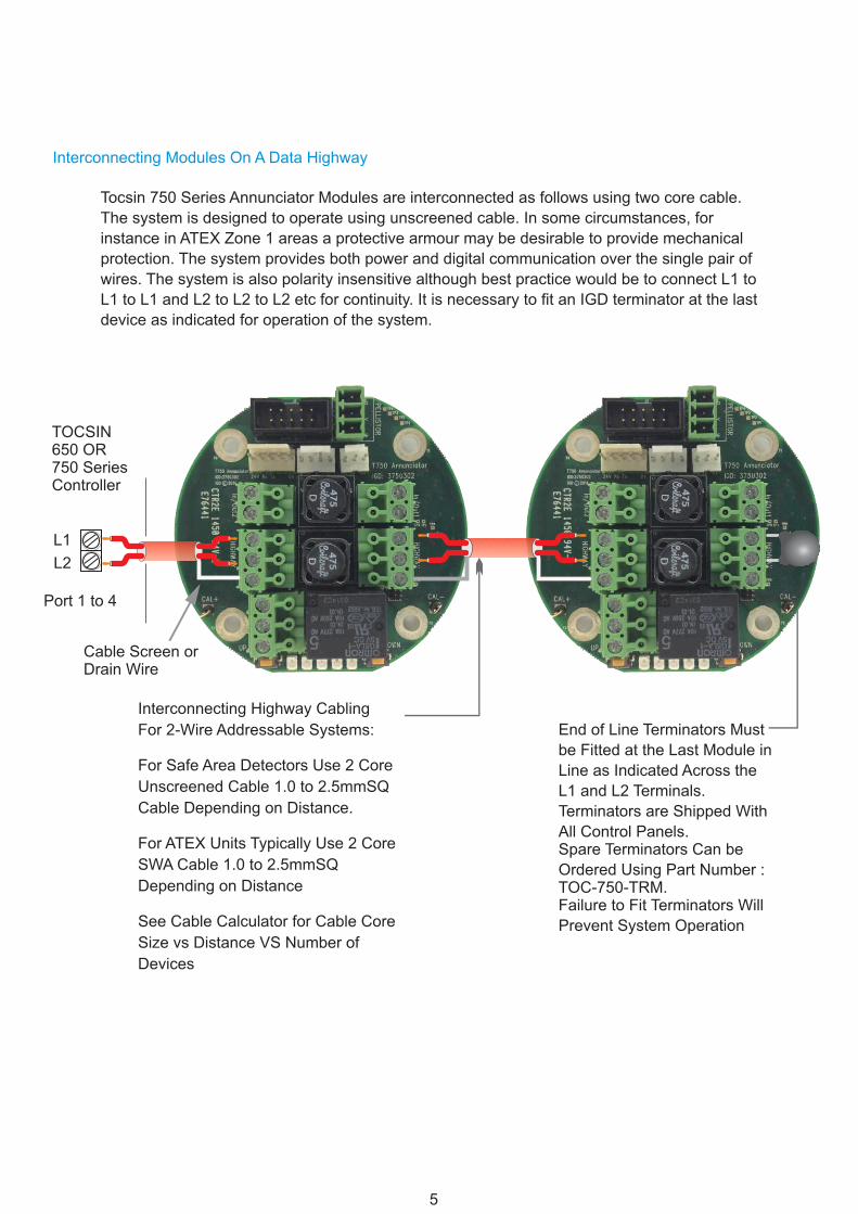
Interconnecting Modules On A Data Highway
Interconnecting Highway Cabling
For 2-Wire Addressable Systems:
For Safe Area Detectors Use 2 Core
Unscreened Cable 1.0 to 2.5mmSQ
Cable Depending on Distance.
For ATEX Units Typically Use 2 Core
SWA Cable 1.0 to 2.5mmSQ
Depending on Distance
See Cable Calculator for Cable Core
Size vs Distance VS Number of
Devices
End of Line Terminators Must
be Fitted at the Last Module in
Line as Indicated Across the
L1 and L2 Terminals.
Terminators are Shipped With
All Control Panels.Spare Terminators Can be
Ordered Using Part Number :TOC-750-TRM.Failure to Fit Terminators Will
Prevent System Operation
Tocsin 750 Series Annunciator Modules are interconnected as follows using two core cable.
The system is designed to operate using unscreened cable. In some circumstances, for
instance in ATEX Zone 1 areas a protective armour may be desirable to provide mechanical
protection. The system provides both power and digital communication over the single pair of
wires. The system is also polarity insensitive although best practice would be to connect L1 to
L1 to L1 and L2 to L2 to L2 etc for continuity. It is necessary to fit an IGD terminator at the last
device as indicated for operation of the system.
TOCSIN650 OR750 SeriesController
L1
L2
Port 1 to 4
Cable Screen orDrain Wire
International Gas Detectors
6
0V DC
24V DC
~~
A1
A1
A2
A2
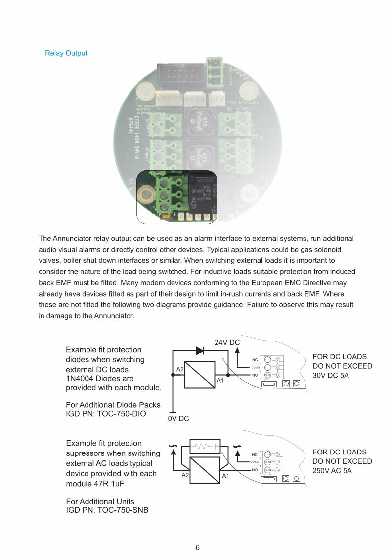
Example fit protection
diodes when switching
external DC loads.1N4004 Diodes areprovided with each module.
For Additional Diode PacksIGD PN: TOC-750-DIO
Example fit protection
supressors when switching
external AC loads typical
device provided with each
module 47R 1uF
For Additional UnitsIGD PN: TOC-750-SNB
Relay Output
The Annunciator relay output can be used as an alarm interface to external systems, run additional
audio visual alarms or directly control other devices. Typical applications could be gas solenoid
valves, boiler shut down interfaces or similar. When switching external loads it is important to
consider the nature of the load being switched. For inductive loads suitable protection from induced
back EMF must be fitted. Many modern devices conforming to the European EMC Directive may
already have devices fitted as part of their design to limit in-rush currents and back EMF. Where
these are not fitted the following two diagrams provide guidance. Failure to observe this may result
in damage to the Annunciator.
NC
COMM
NO
NC
COMM
NO
FOR DC LOADS
DO NOT EXCEED
30V DC 5A
FOR DC LOADS
DO NOT EXCEED
250V AC 5A
International Gas Detectors
7
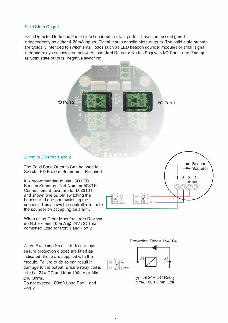
Solid State Output
The Solid State Outputs Can be used to Switch LED Beacon Sounders if Required.
It is recommended to use IGD LED Beacon Sounders Part Number 5083101Connections Shown are for 5083101and shown one output switching the beacon and one port switching the sounder. This allows the controller to mute the sounder on accepting an alarm.
When using Other Manufacturers Devices do Not Exceed 100mA @ 24V DC Total combined Load for Port 1 and Port 2
I/O Port 2
When Switching Small interface relays
ensure protection diodes are fitted as
indicated, these are supplied with the
module. Failure to do so can result in
damage to the output. Ensure relay coil is
rated at 24V DC and Max 100mA or Min
240 Ohms.Do not exceed 100mA Load Port 1 and
Port 2
I/O Port 1I/O Port 2
Wiring to I/O Port 1 and 2
Each Detector Node has 2 multi-function input - output ports. These can be configured
independently as either 4-20mA inputs, Digital Inputs or solid state outputs. The solid state outputs
are typically intended to switch small loads such as LED beacon sounder modules or small signal
interface relays as indicated below. As standard Detector Nodes Ship with I/O Port 1 and 2 setup
as Solid state outputs, negative switching
V+
4-20mA
A1 A2
Protection Diode 1N4004
Typical 24V DC Relay15mA 1600 Ohm Coil
V+
4-20mA
1 2 3 4IN+ OUT+
BeaconSounder
International Gas Detectors
8
Digital Input
I/O Port 1I/O Port 2
Wiring to I/O Port 1 and 2
Each Detector Node has 2 multi-finction input - output ports. These can be configured
independently as either 4-20mA inputs or solid state outputs. The digital inputs are typically
intended to totalise pulse counts, mainly from gas meters, or use for slam switch/ E-Stop
applications
V+
4-20mA
V+
4-20mA
V+
4-20mA
The Solid State Input Will Accept up to a 0.2 Hz Pulse Train Input From a Gas Meter or Similar Device. Typically 0.2Hz equates to 7.2M3/Hr @ 1 Pulse/0.01M3
If You Are Wiring Digital Inputs (24V) Option Then You Need to Include a 560 Ohm Resistor to Limit Current Around the Circuit
If You Are Wiring Digital Inputs (0V) Option Allows Logic inputs from External Devices.Anything Less Than 1.5V DC is Treated as Off Anything Greater is On
Wiring to I/O Port 1 and 2
TOC-10 Unit 1 TOC-10 Unit 2
External System
V+
4-20mA
SpareI/O0V
SpareI/O0V
0VI/O Digital
Solid State Input From TOC-10 Gas Detector
The Solid State Input can be used to interface to IGD TOC-10 Series Flammable Gas Detectors. Wire as Indicated and the Input Will Read the Two Alarm Levels From the TOC-10. This will display on an Addressable Controller in the Same Manner as Any Other Gas Detector.Up to 6 TOC-10 Detectors can be Daisy Chained to the Input
International Gas Detectors
9
V+
4-20mA
V+
4-20mA
4-20 mA Inputs
The Input Sources a 24V DC supply thensinks the signal current on the module PCB across a 122 Ohm resistor on the PCB
24V DC Power is supplied from an external source then sinks the signal current on the module PCB across a 100 Ohm resistor on the PCB. Note the 0V DC Common Connection.
I/O Port 1I/O Port 2
Wiring to I/O Port 1 and 2
a) For a 2 Wire Loop Powered Device (4-20MA 24V Option)
b) For a 2 Wire 4-20mA Device Externally Powered Device (4-20MA 0V Option)
Each Detector Node has 2 multi-finction input - output ports. These can be configured
independently as either 4-20mA inputs or solid state outputs. When used as 4-20mA inputs any
standard 4-20mA loop powered can be read in as an analogue signal. Using the setup routine the
signal can be scaled and then read back addressably onto the system controller.
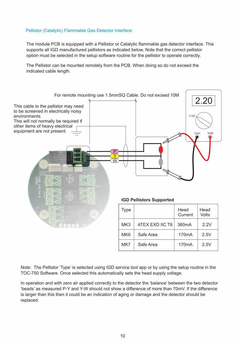
Pellistor (Catalytic) Flammable Gas Detector Interface
PYW
The module PCB is equipped with a Pellistor or Catalytic flammable gas detector interface. This
supports all IGD manufactured pellistors as indicated below. Note that the correct pellistor
option must be selected in the setup software routine for the pellistor to operate correctly.
The Pellistor can be mounted remotely from the PCB. When doing so do not exceed the
indicated cable length.
For remote mounting use 1.5mmSQ Cable. Do not exceed 10M
V DC
VoltsCom
2.20
IGD Pellistors Supported
Type Head Head Current Volts
MK3 ATEX EXD IIC T6 360mA 2.2V
MK6 Safe Area 170mA 2.5V
MK7 Safe Area 170mA 2.5V
This cable to the pellistor may need to be screened in electrically noisy environments.This will not normally be required if other items of heavy electrical equipment are not present
Note: The Pellistor ‘Type’ is selected using IGD service tool app or by using the setup routine in the
TOC-750 Software. Once selected this automatically sets the head supply voltage.
In operation and with zero air applied correctly to the detector the ‘balance’ between the two detector
‘beads’ as measured P-Y and Y-W should not show a difference of more than 70mV. If the difference
is larger than this then it could be an indication of aging or damage and the detector should be
replaced.
International Gas Detectors
11
Module Indications
Connected Status
Each module has two push buttons, labelled up and down and five LED’s. In operation the
LEDs and buttons work together to allow local calibration, change or reading of the base
address or connected status as follows:
LED 1Lit Green if pellistor option activatedFlashing green see table
LED 5Lit Green if Relay option activatedFlashing green see table
LED 2Lit Green if IR-PID-Toxic option activatedFlashing green see table
LED 4Lit Green if I/O Port 2 option activatedFlashing green see table
LED 3Lit Green if I/O Port 1 option activatedFlashing green see table
Note the LED flash rate is used to indicate as follows:
LED Flash Rate
ON no Flash
1 per Second
5 per Second
1 per 10 Seconds
Indicates
Option Enabled and Powered But No Communication
Option Enabled Powered and Communication All OK
Line Voltage Low only LED 1 then LED 5
Option Has a Fault Condition
Note: IGD App is used to configure the module PCB to switch devices on and off and set addresses (see Tocsin 650/750 Manual).
International Gas Detectors
12
Addressing the Assembly
The TOC-750 Module PCB is an Addressable Device and Comes Equipped With a Simple Interface to Allow the Base Address to be Set. To Set The Set Address,
Press and hold the Down button for >2s
Release Button the Light Pattern Will Now Indicate the set Address as Shown in the Table Below.
With the Set Address Lit, the UP and DOWN buttons can now be used to alter the address if required
With the Required Address lit, Press and Hold the DOWN Button Until the LED’s go out. Release the DOWN button and the new Base Address is Now Set.
Note That with the base address set the LED’s revert to showing what options are active and which of those options are communicating, see previous section on ‘Module Indications’.
00
08
16
24
01
09
17
25
02
10
18
26
03
11
19
27
04
12
20
28
05
13
21
29
06
14
22
30
07
15
23
31
Setting the base address using the button interface sets the address for all other active options on the module as follows:For a Base Address Set of 01:
NOTE: WHEN SETTING ADDRESSES YOU CANNOT HAVE TWO DEVICE ADDRESSES SET THE SAME ON THE SAME ADDRESSABLE HIGHWAY or DEVICE.
Pellistor Input = Base Address = 0102 = IR/PID/Toxic or Oxygen Sensor03 = Digital or analogue Input 104 = Digital or analogue input 205 = E-Stop06 = Key Switch
101 = Relay & Sounder102 = Digital Output 1103 = Digital Output 2104 = Display Sounder
SYSTEM STATUS
EDIT 19
Note when editing if anAnnunciator Display isfitted the base addressdisplay will also update
UP DOWN1 2 3 4 5
UP DOWN1 2 3 4 5
Anything turned off is ignored. Addresses are allocated in the following sequence.
1 2 3 4 5 1 2 3 4 5
International Gas Detectors
13
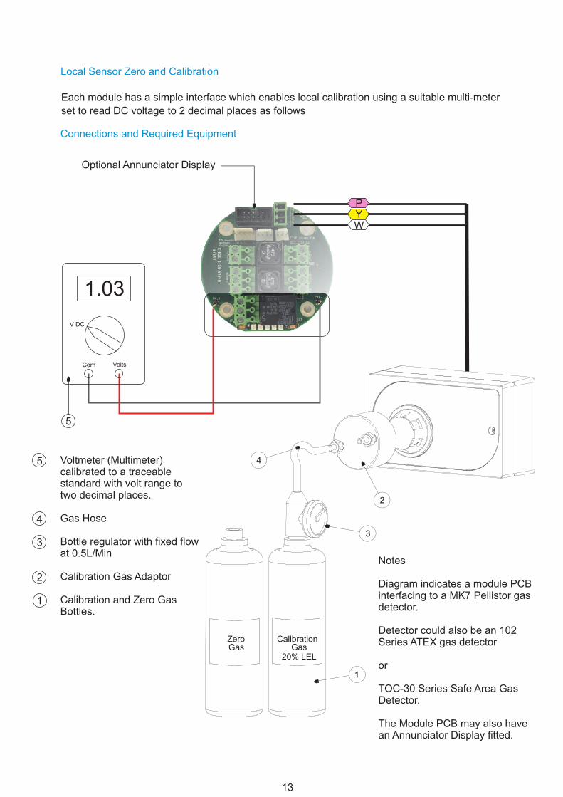
Local Sensor Zero and Calibration
Connections and Required Equipment
Each module has a simple interface which enables local calibration using a suitable multi-meter
set to read DC voltage to 2 decimal places as follows
CalibrationZeroGasGas
20% LEL
1
2
3
4
PYW
V DC
VoltsCom
1.03
5
Voltmeter (Multimeter) calibrated to a traceable standard with volt range to two decimal places.
Gas Hose
Bottle regulator with fixed flow at 0.5L/Min
Calibration Gas Adaptor
Calibration and Zero Gas Bottles.
5
4
3
2
1
Notes
Diagram indicates a module PCB interfacing to a MK7 Pellistor gas detector.
Detector could also be an 102 Series ATEX gas detector
or
TOC-30 Series Safe Area Gas Detector.
The Module PCB may also have an Annunciator Display fitted.
Optional Annunciator Display
International Gas Detectors
14
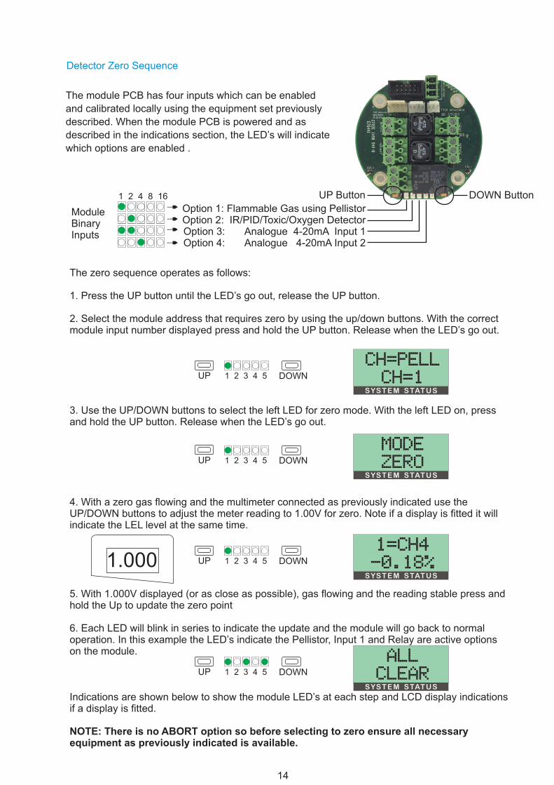
Detector Zero Sequence
The module PCB has four inputs which can be enabled
and calibrated locally using the equipment set previously
described. When the module PCB is powered and as
described in the indications section, the LED’s will indicate
which options are enabled .
Option 1: Flammable Gas using PellistorOption 2: IR/PID/Toxic/Oxygen Detector Option 3: Analogue 4-20mA Input 1Option 4: Analogue 4-20mA Input 2
UP Button DOWN Button
The zero sequence operates as follows:
1. Press the UP button until the LED’s go out, release the UP button.
2. Select the module address that requires zero by using the up/down buttons. With the correct module input number displayed press and hold the UP button. Release when the LED’s go out.
3. Use the UP/DOWN buttons to select the left LED for zero mode. With the left LED on, press and hold the UP button. Release when the LED’s go out.
4. With a zero gas flowing and the multimeter connected as previously indicated use the UP/DOWN buttons to adjust the meter reading to 1.00V for zero. Note if a display is fitted it will indicate the LEL level at the same time.
5. With 1.000V displayed (or as close as possible), gas flowing and the reading stable press and hold the Up to update the zero point
6. Each LED will blink in series to indicate the update and the module will go back to normal operation. In this example the LED’s indicate the Pellistor, Input 1 and Relay are active optionson the module.
Indications are shown below to show the module LED’s at each step and LCD display indications if a display is fitted.
NOTE: There is no ABORT option so before selecting to zero ensure all necessary equipment as previously indicated is available.
UP
UP
UP
UP
DOWN
DOWN
DOWN
DOWN
1 2 3 4 5
1 2 3 4 5
1 2 3 4 5
1 2 3 4 5
1 2 4 8 16
ModuleBinaryInputs
SYSTEM STATUS
SYSTEM STATUS
SYSTEM STATUS
SYSTEM STATUS
ch=pellch=1
modezero
1=ch4-0.18%
allclear
1.000
International Gas Detectors
15
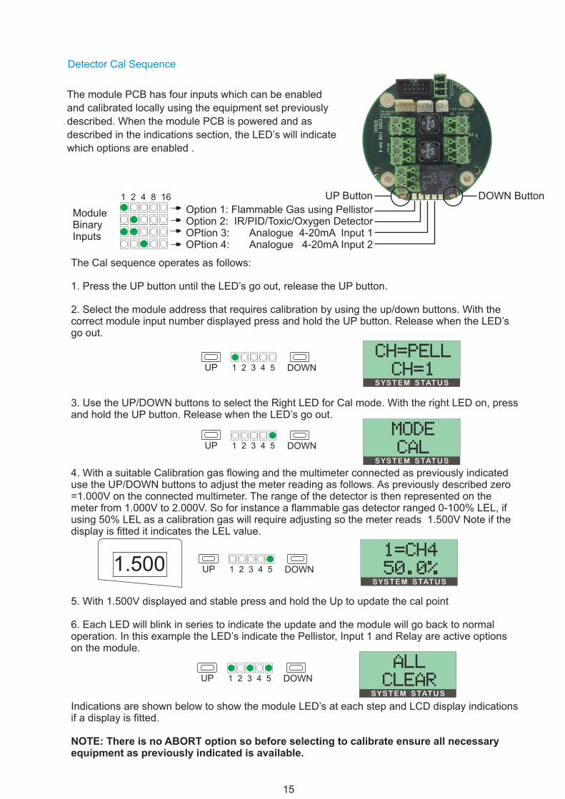
The Cal sequence operates as follows:
1. Press the UP button until the LED’s go out, release the UP button.
2. Select the module address that requires calibration by using the up/down buttons. With the correct module input number displayed press and hold the UP button. Release when the LED’s go out.
3. Use the UP/DOWN buttons to select the Right LED for Cal mode. With the right LED on, press and hold the UP button. Release when the LED’s go out.
4. With a suitable Calibration gas flowing and the multimeter connected as previously indicated use the UP/DOWN buttons to adjust the meter reading as follows. As previously described zero =1.000V on the connected multimeter. The range of the detector is then represented on the meter from 1.000V to 2.000V. So for instance a flammable gas detector ranged 0-100% LEL, if using 50% LEL as a calibration gas will require adjusting so the meter reads 1.500V Note if the display is fitted it indicates the LEL value.
5. With 1.500V displayed and stable press and hold the Up to update the cal point
6. Each LED will blink in series to indicate the update and the module will go back to normal operation. In this example the LED’s indicate the Pellistor, Input 1 and Relay are active optionson the module.
Indications are shown below to show the module LED’s at each step and LCD display indications if a display is fitted.
NOTE: There is no ABORT option so before selecting to calibrate ensure all necessary equipment as previously indicated is available.
UP
UP
UP
UP
DOWN
DOWN
DOWN
DOWN
1 2 3 4 5
1 2 3 4 5
1 2 3 4 5
1 2 3 4 5
SYSTEM STATUS
SYSTEM STATUS
SYSTEM STATUS
SYSTEM STATUS
ch=pellch=1
modecal
1=ch450.0%
allclear
Detector Cal Sequence
The module PCB has four inputs which can be enabled
and calibrated locally using the equipment set previously
described. When the module PCB is powered and as
described in the indications section, the LED’s will indicate
which options are enabled .
Option 1: Flammable Gas using PellistorOption 2: IR/PID/Toxic/Oxygen Detector OPtion 3: Analogue 4-20mA Input 1OPtion 4: Analogue 4-20mA Input 2
UP Button DOWN Button1 2 4 8 16
ModuleBinaryInputs
1.500
International Gas Detectors
16
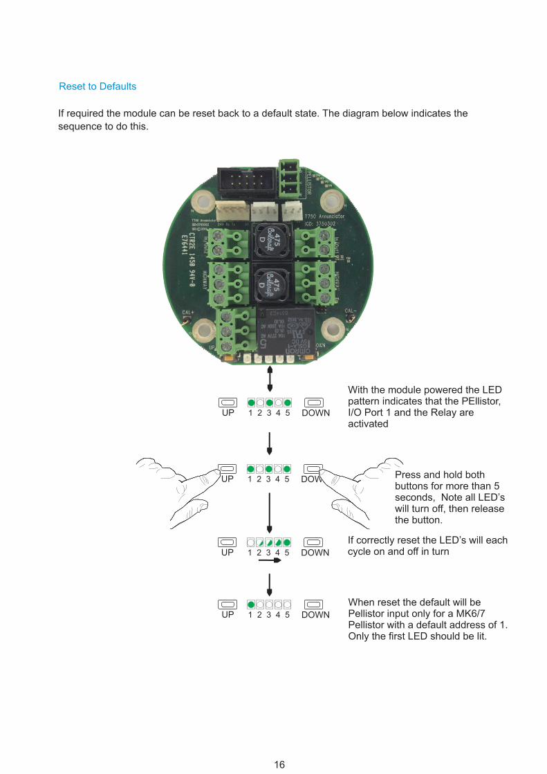
Reset to Defaults
If required the module can be reset back to a default state. The diagram below indicates the
sequence to do this.
UP
UP
UP
UP
DOWN
DOWN
DOWN
DOWN
1 2 3 4 5
1 2 3 4 5
1 2 3 4 5
1 2 3 4 5
With the module powered the LED pattern indicates that the PEllistor, I/O Port 1 and the Relay are activated
When reset the default will be Pellistor input only for a MK6/7 Pellistor with a default address of 1. Only the first LED should be lit.
If correctly reset the LED’s will each cycle on and off in turn
Press and hold both buttons for more than 5 seconds, Note all LED’s will turn off, then release the button.
International Gas Detectors
17
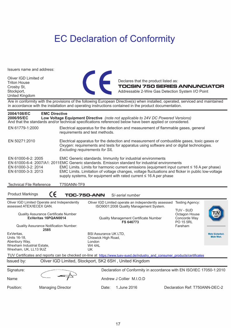
Declares that the product listed as:
TOCSIN 750 SERIES ANNUNCIATOR Addressable 2-Wire Gas Detection System I/O Point
EC Declaration of Conformity
Issuers name and address:
Oliver IGD Limited ofTriton HouseCrosby St, Stockport,United Kingdom
Issued by: Oliver IGD Limited, Stockport, SK2 6SH , United Kingdom
Signature: Declaration of Conformity in accordance with EN ISO/IEC 17050-1:2010
Name Andrew J Collier M.I.O.D
Position: Managing Director Date: 1.June 2016 Declaration Ref: T750ANN-DEC-2
Are in conformity with the provisions of the following European Directive(s) when installed, operated, serviced and maintained in accordance with the installation and operating instructions contained in the product documentation.
And that the standards and/or technical specifications referenced below have been applied or considered.
2004/108/EC EMC Directive 2006/95/EC Low Voltage Equipment Directive (note not applicable to 24V DC Powered Versions)
EN 61779-1:2000
EN 50271:2010
EN 61000-6-2: 2005EN 61000-6-4: 2007/A1: 2011EN 61000-3-2: 2014EN 61000-3-3: 2013
Technical File Reference
Electrical apparatus for the detection and measurement of flammable gases, general requirements and test methods.
Electrical apparatus for the detection and measurement of combustible gases, toxic gases or Oxygen: requirements and tests for apparatus using software and or digital technologies. Excluding requirements for SIL
EMC Generic standards. Immunity for industrial environmentsEMC Generic standards. Emission standard for industrial environmentsEMC Limits. Limits for harmonic current emissions (equipment input current ≤ 16 A per phase)EMC Limits. Limitation of voltage changes, voltage fluctuations and flicker in public low-voltage supply systems, for equipment with rated current ≤ 16 A per phase