MODEL 9100 AUTOMATED TELLER MACHINE USER MANUAL VERSION 1.0 TDN 07100-00080 04/2007 COPYRIGHT NOTICE ' 2002 - 2007 Delaware Capital Formation, Inc. All Rights Reserved. Triton Systems of Delaware, Inc. is an operating company of Dover Electronics, Inc., a subsidiary of Dover Corporation (NYSE-DOV). DOVER, the DOVER logo and the family of marks and TRITON, the TRITON logo and the Triton family of marks are registered trademarks of Delaware Capital Formation, Inc., a wholly owned subsid- iary of Dover Corporation. CORPORATE HEADQUARTERS: 522 E. Railroad Street Long Beach, MS 39560 Phone: (228) 868-1317 Fax: (228) 868-0437 RMA (RETURN MATERIAL AUTHORIZATION) RETURN ADDRESS: 21405 Avenue B Long Beach, MS 39560
This publication is protected by copyright and all rights are reserved. No part of it may be reproduced ortransmitted by any means or in any form, without prior consent in writing from Triton Systems of Dela-ware, Inc.
The information in this publication has been carefully checked and is believed to be accurate. However,Triton Systems of Delaware, Inc. assumes no responsibility for any inaccuracies, errors, or omissionsthat may be contained in this document. In no event will Triton Systems of Delaware, Inc. be liable fordirect, indirect, special, incidental, or consequential damages resulting from any defect or omission in thismanual, even if advised of the possibility of such damages.
In the interest of continued product development, Triton Systems of Delaware, Inc. reserves the right tomake improvements in its documentation and the products it describes at any time, without notice orobligation.
TRADEMARK ACKNOWLEDGEMENTS
Triton Connect is a trademark of Triton Systems of Delaware, Inc. VISA® is a registered trademark ofVISA of the United States and other countries.
iii
MODEL 9100 USER MANUAL
CONTENTS
SECTION 1 - INTRODUCTION ........................................................................................ 1WHAT�S IN THIS MANUAL .......................................................................................................................2FEATURE HIGHLIGHTS ..............................................................................................................................3STANDARD FEATURES ..............................................................................................................................4
SECTION 3 - MANAGEMENT FUNCTIONS ....................................................................... 15INTRODUCTION ........................................................................................................................................16ACCESSING THE MANAGEMENT FUNCTIONS MENU ....................................................................................16NEW OR MODIFIED MANAGEMENT FUNCTIONS ..........................................................................................17
MAIN MENU .......................................................................................................................... 18CONFIGURE TERMINAL ........................................................................................................... 19
CASSETTE SETUP ..............................................................................................................................19DATE / TIME FUNCTIONS ..................................................................................................................19LANGUAGE IDIOMA ..........................................................................................................................19PRINTER SETTINGS ...........................................................................................................................19ATM MONITORING .........................................................................................................................19PASSWORD MAINTENANCE ...............................................................................................................19MORE .............................................................................................................................................20AD SCREENS ..................................................................................................................................20RANDOM / LEVEL PROZE COUPONS ...................................................................................................20CHANGE MESSAGES ........................................................................................................................20COMMUNICATION .............................................................................................................................20ADJUST CONTRAST ...........................................................................................................................20LOCAL ZIP CODE .............................................................................................................................20MORE .............................................................................................................................................20SPEECH ON / OFF ............................................................................................................................20VIEW / MODIFY OPTIONS .................................................................................................................20
CASSETTE SERVICE ................................................................................................................ 31
DIAGNOSTICS .......................................................................................................................... 32STATUS ...................................................................................................................................................32PURGE ...................................................................................................................................................32TEST DISPENSE .......................................................................................................................................32FORMAT GRAPHIC MEMORY .....................................................................................................................32TEST RECEIPT PRINTER ............................................................................................................................32VERSION #�S ..........................................................................................................................................32MORE DIAGNOSTICS ..............................................................................................................................33INJECT NEW CASSETTE ID ........................................................................................................................33COMMUNICATION ....................................................................................................................................33MODEM SPEAKER ON / OFF ....................................................................................................................33FORCE UNLOCK ......................................................................................................................................33PRINT DISPENSER STATUS ........................................................................................................................33CLEAR DISPENSER STATUS .......................................................................................................................33PREVIOUS ...............................................................................................................................................33MORE (MORE) DIAGNOSTICS .................................................................................................................34KEYPAD .................................................................................................................................................34CLEAR TAMPER ......................................................................................................................................34CLEAR SERIAL TAMPER ..........................................................................................................................34STATUS ...................................................................................................................................................34SCAN CARD ...........................................................................................................................................34
JOURNAL ................................................................................................................................ 37PRINT JOURNAL ......................................................................................................................................37CLEAR JOURNAL .....................................................................................................................................37PRINT LAST X ENTRIES ............................................................................................................................37
CLOSE ................................................................................................................................... 35SCHEDULE CLOSE ...................................................................................................................................35TRIAL CLOSE ..........................................................................................................................................35DAY CLOSE ............................................................................................................................................35TRIAL CASSETTE CLOSE (ALL) .................................................................................................................35CASSETTE CLOSE ...................................................................................................................................36CASSETTE A-D .......................................................................................................................................36TRIAL CASSETTE CLOSE ...........................................................................................................................36SELECT CASSETTE ...................................................................................................................................36ENTER QTY IN CASSETTE ..........................................................................................................................36
vi
MODEL 9100 USER MANUAL
SECTION 5 - GENERAL MAINTENANCE ........................................................................... 65INTRODUCTION ........................................................................................................................................66REPLENISH RECEIPT PAPER ............................................................................................................................. 66-68CLEANING THE ENCLOSURE .....................................................................................................................69CLEANING THE DISPLAY ..........................................................................................................................69CARD READER CLEANING ........................................................................................................................69
APPENDIX A - WARRANTY AND REPAIR POLICIES/PROCEDURES ..................................... A-1
APPENDIX B - COMBINATION / ELECTRONIC LOCKS ..................................................... B-1
APPENDIX C - TDM �BACKGROUND PAPER� .............................................................. C-1
SUPPLEMENT A (US / MEXICO) .................................................................................... SA-1
SUPPLEMENT B (CANADA) ............................................................................................ SB-1
SUPPLEMENT C (SOUTH AFRICA) .................................................................................. SC-1
SUPPLEMENT D (US) ................................................................................................... SD-1
SUPPLEMENT E (CANADA) ............................................................................................ SE-1
SUPPLEMENT F (UK) ................................................................................................... SF-1
SUPPLEMENTS
viii
MODEL 9100 USER MANUAL
THIS PAGE INTENTIONALLY LEFT BLANK
1
SECTION 1INTRODUCTION
2
MODEL 9100 USER MANUAL
WHAT�S IN THIS MANUAL
This revised User manual describes the operating features of the Model 9100 series ATM and shows howto perform the procedures that would typically be performed by the owner or operator personnel.
The manual is divided into the following sections:
SECTION 1, INTRODUCTION. Summarizes the basic features of the Model 9100 series ATM.
SECTION 2, BASIC OPERATION. Describes the basic operation of the terminal.:
SECTION 3, MANAGEMENT FUNCTIONS. Describes the menu functions and available options.
SECTION 4, CASSETTE CLOSE / CASH REPLENISHMENT. Describes the menu functions for cassette closeprocedures. Cash replenishment standards and loading steps are covered as well as putting cassettesback in service.
SECTION 5, GENERAL MAINTENANCE. Describes normal preventative and corrective maintenance proce-dures appropriate for user personnel.
! Replenishing Receipt Paper! Cleaning the Enclosure/Card Reader
Section 6, TDM Error Codes / Click Counts. Tables provided to help identify error conditions andtroubleshooting.
APPENDIX A, WARRANTY AND REPAIR POLICIES / PROCEDURES
APPENDIX B, COMBINATION / ELECTRONIC LOCKS. Covers how to change combinations for mechanical andelectronic locks. Also provides procedures for changing the battery in the electronic lock.
SUPPLEMENT A. Describes software changes implemented in the March, 06� version of 8100/9100 US/Mexico software release.
SUPPLEMENT B. Describes software changes implemented in the April, 06� version of 8100/9100 Canadiansoftware release.
APPENDIX C, TALKING PAPER (TDM MECHANISMS)
3
INTRODUCTION
FEATURE HIGHLIGHTS
Important features of the 9100 series ATM are highlighted in the following list:
" Modular architecture eases troubleshooting and servicing.
" Supports dial-up and Ethernet (TCP/IP) communications.
" Accomodates single or multi-cassette dispensing mechanisms (TDM-100/150/200/250/SDD/Minimech).
" 5.7" (145 mm) monochrome or color LCD display.
" 14.4 baud modem standard (33.6 baud optional).
" Satisfies Americans with Disabilities Act (ADA) specifications for height and access. Audio compliant.
" VISA® Encrypting PIN Pad (VEPP) to comply with international encryption standards and TripleDES compliant.
" Dip-style card reader (EMV optional).
" 60 mm thermal printer designed for quiet operation.
" Mechanical or electronic combination lock .
" Supports remote setup, configuration, and monitoring via Triton Connect� ATM monitoring software.
" Dispenses U.S. and international currency types.
" High-capacity electronic journal stores transaction details for later printout and analysis.
" Small footprint design makes placement easier. Deeper cabinet available to accomodate SDD dispenser.
" Choice of control panel and fascia color available in Blue or Bayou Bronze.
SUPPLEMENT C. Describes software changes implemented in the May, 06� version of 8100/9100 SouthAfrica software release.
SUPPLEMENT D. Descibes software changes implemented in the February, 07� version of 8100/9100 USsoftware release.
SUPPLEMENT E. Describes software changes implemented in the Mar, 07� version of 8100/9100 Canadiansoftware release.
SUPPLEMENT F. Descibes software changes implemented in the Mar, 07� version of 8100/9100 UK softwarerelease.
4
MODEL 9100 USER MANUAL
STANDARD FEATURES
" Management Functions. Enable extensive control and customization of the ATM�s operatingparameters.
" EPROM Functions. The EPROM function provides low-level diagnostic and software updateoperations.
" Password Protection. Access to Management Functions, EPROM, and Key Management areas areprotected with passwords.
" MAC Encryption Support. Message Authentication Code (MAC) data encryption protocol. Providesincreased protection for message traffic to and from the ATM. Triple DES compliant.
" Encrypting PIN Pad (EPP) Entry Device Support. Secure EPP device encrypts the customer PINduring a transaction. Triple DES compliant.
" Multi-Language Support. Enables the customer to select a preferred language (such as French orSpanish) for customer screens and receipts.
" Transaction and Account Type Configuration. Enables selection of transactions (transfers or balanceinquiries) or accounts (savings or credit card) that will be presented to the customer. Does not affectavailability of checking account withdrawal.
" Cassette and Day Close Reports. Provide summary information about the number and type oftransactions being performed by the ATM.
" Electronic Journal. Stores the details of each transaction in solid-state memory. Journal data can beretrieved, printed out at the receipt printer, and transferred to a remote Triton Connect computer.
" AD Screens. An Ad screen is a promotional or advertising graphic that is displayed on the LCDscreen during idle periods. Ad screens are downloaded to the terminal by a remote Triton Connect�computer. Text-only (non-graphic) Ad screens can also be displayed.
" Receipt Printer Graphics. This feature allows informational or promotional graphics to be printedon customer receipts.
" Messages. Informational and promotional messages that are displayed to the customer on-screen orprinted on receipts.
" Coupons. Coupons are printed by the receipt printer and prizes awarded to customers based onrandom and/or withdrawal amount-based transactions. Coupon text can be entered locally ordownloaded along with coupon graphics using Triton Connect� software.
5
INTRODUCTION
" Status Monitoring. The ATM can periodically transfer status information to the host processor. Inaddition, Triton Connect� remote monitoring software can be used to view the journal, monitoroperation and alarm conditions, update operating parameters, and reset the terminal.
" UL 291 certified for Business Hours service. This means that the currency should be removed fromthe dispenser and stored in a safe location when the business is closed to the public.
" Front-access cabinet. Allows access to the dispensing mechanism and currency cassette from thecontrol-panel side of the unit.
6
MODEL 9100 USER MANUAL
THIS PAGE INTENTIONALLY LEFT BLANK
SECTION 2BASIC OPERATION
7
8
MODEL 9100 USER MANUAL
INTRODUCTION
This section describes the basic operation of the terminal. The following topics are covered:
1. CONTROL PANEL LAYOUT. Describes the layout of the terminal�s control panel.
2. KEYPAD OPERATION. Describes the use of the alphanumeric keypads.
3. MENU-BASED OPERATION. Gives a general overview of the terminal display interface.
4. CUSTOMER TRANSACTIONS. Summarizes the actions involved in typical customer transactions. Inaddition, the voice-enabled transactions feature is described.
CONTROL PANEL LAYOUT
The user interface of the terminal consists of the LCD screen, receipt chute, card reader, speaker, head-phone jack (visually impaired), and 24 keys on three keypads. The Function keys are arranged in twofour-key groups, one group on either side of the LCD display. The main keypad consists of 10 alphanu-meric keys, two arrow keys and four large control keys, all located in a 16-key group beneath the LCDscreen.The main keypad and control keys have an integral raised Braille symbol to conform to the requirementsof the Americans with Disabilities Act (Figure 2-1).
Figure 2-1. Control panel layout.
LCD screen
Mainkeypad
Cardreader
Functionkeys
Receiptchute
Headphone jack
9
BASIC OPERATION
FUNCTION KEYPADS
The primary menu navigation keys, called Function keys, are arranged in two four-key groups, one groupon either side of the LCD screen. A Function key is only active when a function or menu option name isdisplayed (if the display is �grayed out�, that option is not available). The Function keys are designatedF1 through F8, as shown in Figure 2-2.
Figure 2-2. Function key layout.
MAIN KEYPAD
The entry of numeric characters via the main keypad is straightforward: simply press the desired key.However, in certain Management Function screens it may be necessary to enter alphabetic characters, aprocedure that requires a little more explanation. On such screens, a flashing cursor will be evident on thedisplay, representing the location where the next character you enter will be displayed. To enter a letter orpunctuation mark, you will first press the <CTRL> key (the blank key in the lower right-hand corner of thekeypad), and then you will press the number that has the letter or other character you want.
1QZ
2ABC
3DEF
4GHI
5JKL
6MNO
7PRS
8TUV
9WXY
0< >
xCANCEL
<CLEAR
OENTER
Figure 2-3.Alphanumeric
keypad.
CTRL
10
MODEL 9100 USER MANUAL
SRETCARAHCDAPYEK-1-2ELBAT
1X 2X 3X 4X 5X 6X
1 Q Z ecapS ~ ! @
2 A B C # $ %
3 D E F ^ * _
4 G H I ( ) |
5 J K L \ / "
6 M N O ; :'
)nepO(etouQelgniS
7 P R S ? < >
8 T U V [ ] ñ
9 W X Y { }'
)esolC(etouQelgniS
0 , . - & = +
Table 2-1. Keypad characters.
Each of the numbered keys (<0> through <9>) has six characters available. See Table 2-1, Keypadcharacters. On most of these keys (<2> through <9>), the first three of the available characters arealphabetic, and are printed on the keycap above the number character. Two keys, the <0> and <1>, aredifferent. The <0> key does not show any additional characters, while the <1> key shows two alphabeticcharacters (�QZ�).
The first character on the first key (0-9) you press after the <CTRL> key will be displayed at the currentcursor position. Pressing the same key repeatedly (X1-X6) will cycle the displayed letter through theavailable character choices for that key.
When the desired character is displayed, press the <RIGHT ARROW> key to �lock it in� and move thecursor to the next position. Repeat these steps to enter the next character.
The <RIGHT ARROW> and <LEFT ARROW> keys are used in most alphanumeric data entry situations.The <LEFT ARROW> is used to back up and erase a character. The <RIGHT ARROW> is used to lock ina character. These keys will auto-repeat if held down for more than one second.
The <CLEAR> key can be used to clear an entry and start over. The <CANCEL> key will abort the currenttransaction.
11
BASIC OPERATION
When a screen timeout occurs, a screen is presented which asks the user if more time is needed. If theuser chooses NO, the Customer Welcome screen will be presented. If YES is chosen, the user is returnedto the function that was active prior to the timeout. If the user does not make a selection within anadditional 30-second countdown period the terminal will automatically go to the Customer Welcomescreen.
When the unit is turned on, the dispenser will beep once and the Top menu, shown in Figure 2-4, willappear on the display screen after a few seconds. From the Top menu, you can either:
1. Activate the terminal to perform customer transactions by pressing the key next to CUSTOMERTRANSACTIONS.
2. Enter the terminal system management area by pressing the key next to MANAGEMENT FUNCTIONS.Note: You will have to enter an appropriate password to view the Management Functions menu.
If you do not select a menu choice within 30 seconds the terminal will automatically default to theCustomer Welcome screen (a benefit of this feature is that in the event of a power interruption the terminalwill automatically begin accepting customer transactions shortly after power is restored).
Figure 2-4. Top menu screen.
MENU-BASED OPERATION
The terminal operates as a menu driven system. Messages and menu options presented on the LCDdisplay screen guide the user�s actions. The desired menu option is selected by pressing one of the keyslocated to the left and right of the display. For the purpose of security many screens timeout after a presettime interval, usually 30 seconds. The timeout length may vary depending on the function being per-formed.
12
MODEL 9100 USER MANUAL
CUSTOMER TRANSACTIONS
A customer begins a transaction by selecting from the Customer screen options. They nsert their ATMcard into the card reader of the terminal. The card must be inserted so that the magnetic stripe can bescanned by the card reader�s sensor. If the customer inserts the card incorrectly, a warning message willbe displayed, accompanied by several beeps to get their attention.
If there is a problem reading a card, make sure the customer is inserting the card correctly. Most problemsare the result of inserting the card incorrectly.
Once the card has been read in successfully, a surcharge message, if applicable, may be displayed (thesurcharge message may be displayed at the end of the customer�s transaction selection). The customermust then enter their secret Personal Identification Number (PIN) code. Once the PIN has been entered,the transaction type and account are selected, and the desired amount of the transaction, if needed. Thetransaction will be processed, typically in a matter of seconds.
Figure 2-5 shows how ATM transactions are handled. If the transaction was processed successfully, thecustomer is prompted to retrieve the requested cash (for withdrawal transactions) and/or the applicabletransaction receipt, as needed. If the transaction was declined, a short receipt indicating the problem isprinted.
BANK
PROCESSOR
ATM ATMNETWORK
Figure 2-5. ATM transaction processing.
13
BASIC OPERATION
The ATM sends the customer transaction request to a processor. A processor is a financial intermediary,such as an Independent Sales Organization (ISO), bank, or other financial institution that providestransaction-processing services for ATMs. The ATM must be set up with a particular processor beforecustomer transactions can take place.
The processor routes the transaction to the appropriate ATM network. An ATM network is a regionallyor nationally organized clearing house for financial transactions, that deals directly with the appropriatefinancial institution, such as the customer�s bank or credit card company, in order to complete thetransaction. The processor will select the appropriate ATM network to use based on factors such as thetype of ATM or credit card used, location of the customer�s bank, or other considerations. The transac-tion may be transferred between several networks before ultimately reaching the customer�s bank orcredit card company.
The ATM network routes the transaction to the appropriate bank or other institution, confirms success-ful completion of the transaction, and sends a confirmation message back to the processor. If the requestwas for a cash withdrawal, an Electronic Funds Transfer (EFT) takes place to debit the funds (includingany surcharge fee, if applicable) from the customer�s bank account and credit the funds to the processor�sbank account.
The processor forwards a confirmation message to the ATM (and an authorization to dispense currency,in the case of a cash withdrawal). The ATM dispenses the requested currency, if necessary, and providesthe customer with a printed receipt as a record of the transaction.
The processor credits the merchant�s account for the amount of any cash withdrawals (plus surchargefees, if collected), typically by the end of the next business day).
14
MODEL 9100 USER MANUAL
VOICE-ENABLED TRANSACTIONS
The terminal provides voice feedback via an integrated output jack, enabling sight-impaired users to plugin a set of headphones and receive spoken instructions to assist them in using the ATM (Figure 2-6).
A raised symbol helps a user locate the headphone jack. The ATM will automatically detect when aheadphone has been plugged into the jack, and will immediately switch into voice mode. Initially, a briefspoken tutorial will orientate the customer to the ATM control panel interface. Once the customer beginsa transaction, spoken prompts will provide feedback and guide the customer through the successfulaccomplishment of the transaction.
Figure 2-6. Headphone jack location.
SECTION 3MANAGEMENT FUNCTIONS
15
16
MODEL 9100 USER MANUAL
Main menu screen (multihost).
INTRODUCTION
This section describes the Management Functions available with the �MASTER� password for accessingthe ATM. When the Customer Welcome screen is displayed, you can access the Management Functionsmenu by following the procedure described next.
ACCESSING THE MANAGEMENT FUNCTIONS MENU
1. Press and hold down the <CTRL> key; while holding down the <CTRL> key, press the <1> key.Release both keys. After a moment the top menu will be displayed.
2. At the top menu, select MANAGEMENT FUNCTIONS by pressing the key next to Management Functionsoption.
3. Enter the user password at the password entry display.
Figure 3-1. Main menu screen (non-multihost).
CHANGE DEFAULT PASSWORDS
A new error code (246) has been created for when the terminal�s MASTER and/or ADMINIS-TRATION password(s) are in the default state. The terminal will detect this condition and goout of service. On the �Out of Service� screen, no error information will be displayed. Thiserror code will not reset until the Master and/or Administration passwords are changed fromtheir default state.
The default MASTER password is �123456� and the default ADMINISTRATION password is�987654�.
* IMPORTANT *NEVER USE THE IDENTICAL PASSWORD FOR BOTH MASTER AND ADMINISTRATION!
17
MANAGEMENT FUNCTIONS
NEW OR MODIFIED MANAGEMENT FUNCTIONS
The majority of the Management Functions are configured the same as before but they may have beenrelocated in the menu structure. A brief synopsis of each function is provided. A summary of the changesto the Management Functions is provided below:
! MAIN MENU - Three (3) major configuration paths now exist: Terminal, Services, and Processors.The other options (Cassette Service, Diagnostics, Close, and Journal) have moved slightly but theirfunctions remain the same.
! DIAGNOSTICS - To reset an on-screen VEPP tamper error �205� or VEPP Serial number error �239�,you must traverse through the Diagnostics menu items. A new option, �KEYPAD�, allows user to cleareither of these 2 error codes.
! Key Management - Two (2) passwords are now required before users can enter the PIN Masterkeys option. Once accessed, two (2) key parts (32 number/character stream) must be loaded, followed bya second part. The Check Digits are displayed before either accepting or declining. An on-screen keypaddirects users for entering numbers and characters.
! COMMUNICATION - This menu item replaces the Telephone Configuration. TCP/IP configurationsetup is now included with the Modem setup.
! TRITON CONNECT� - Moved under �ATM Monitoring�. TCP/IP configuration setup also in-cluded for Triton Connect. The communication type (dial-up or TCP/IP) is automatically detected.
! CONFIGURE PROCESSORS - Processor specific information is now configured under this option.Standard ATM cash transactions WILL use processor number one (1) as its default. Processors 2through 4 reserved for future applications.
! SURCHARGE - You may now block up to one hundred (100) ISOs at the terminal.
! UPDATING SOFTWARE. When installing an update file over any prior software release on a terminalwith a TDM100 or TDM150 dispenser, the cassette multiple amount (value) will need to be reconfiguredbefore the terminal will go into service. You will only have to configure one time after you update. Anyother future releases will not require configuring amount values.
Software UpdatesThere are Supplements at the back of this document that describe new/changed Management function features. Refer to your particular countriesversion for information regarding these updates.
Cassette ServiceMulti-Cassette Dispensers: During the initial boot procedure, the terminal may forcean Error Code 156 to ensure the user enters the Cassette Setup functions to configureand put at least one cassette �In Service�.
18
MODEL 9100 USER MANUAL
NoteIn configuring the parameters , the availability of some options may be �grayedout� due to the specific dispensing mechanism installed or other features.
ACCESS INSTRUCTIONS:1. Access Management Functions by entering your
password. The MAIN MENU screen will be displayed.
DESCRIPTION:
4. Cassette Service. Allows the desired cassette(s) to be placed IN SERVICE.
5. Diagnostics. This function performs self-tests on the major components to help determine andisolate any malfunctions or errors.
6. Close. Used to perform Cassette Close, Day Close, Trial Close, and Schedule Close functions.7. Journal. Journal data is imbedded in the dispenser firmware. The details of each transaction are
stored in the journal�s memory and can be retrieved at a later date. When needed, just theinformation desired can be recalled and a printout of the records made.
MAIN MENU
The Main Menu screen allows the service provider/termi-nal operator to access the following Management functions:
1. Configure Terminal. Used to configure operatingparameters for the ATM terminal.
2. Configure Services. Used to select transactiontypes, account types, and surcharging setup.
3. Configure Processors. Used to configure up to four(4) Host/Processor specific parameters.
* Note: Processor #1 MUST be configured for ATM cashtransactions. Configure the processor prior to ConfiguringServices.
19
MANAGEMENT FUNCTIONS
ACCESS INSTRUCTIONS:1. From the MAIN MENU screen, select CONFIGURE TER-
MINAL.
DESCRIPTION:
The following options will be available from the CONFIGURE
TERMINAL screen:
1. Cassette Setup. Allows the terminal operator to viewand change cassette parameters.
2. Date/Time Functions. Provides a menu related toconfiguration of date and time parameters
3. Language Idioma. Provides access to the optionsthat control the language that is displayed on theATMs LCD display.
5. ATM Monitoring. Allows Triton Connect� setup and enabling, heartbeat messaging, and alarmthresholds.
6. Password Maintenance. Allows access to menus for viewing and changing the Master and Admin-istrative passwords.
7. More. Additional options for couponing, messaging, etc. A listing of items are covered on the nextpage.
CONFIGURE TERMINAL
4. Printer Settings. Provides access to printer receiptlength, low paper acknowledgment, and graphics.
20
MODEL 9100 USER MANUAL
1. AD Screens. This feature enables or disables thedisplay on an idle terminal to alternate between theWelcome Screen and a screen containing graphicsand text elements used to make an advertisementscreen.
5. Adjust Contrast. Adjusts the contrast of the display. *Note: This function not available in Model8100/9100 ATMs. A manual adjust is located on the units Main board.
6. Local Zip Code. Allows entry of the zip code where terminal is located.
7. More. Two (2) more additional options; Speech and View/Modify.
CONFIGURE TERMINAL(MORE)
1. Speech On/Off. Enables/disables the voice-acti-vated headphone jack.
2. View/Modify Options. Allows access for setting aselected feature.
2. Random/Level Prize Coupons. Provides access tosetup terminal operations for issuing printed and dis-pensed prize coupons.
3. Change Messages. Allows information for various terminal and receipt messages to be changedor authored.
4. Communication. Allows modem and/or TCP/IP parameters to be configured and tested.
21
MANAGEMENT FUNCTIONS
ACCESS INSTRUCTIONS:1. From the MAIN MENU screen, select CONFIGURE TER-
MINAL.2. From the CONFIGURE TERMINAL screen, select CAS-
SETTE SETUP.
CASSETTE SETUP
DESCRIPTION:The following options will be available from the CASSETTE
SETUP screen:1. Relearn Bill Thickness. Enables you to force the
dispenser to enter the learning mode (TDM-familydispensers).
2. International Currency. Allows operator to selectone of (128) pre-defined characters as possible mon-etary symbols that describe the type of currencybeing used.
4. Maximum Amount (Non-Cash). Allows operator to set maximum non-cash purchase limit for non-cash items. * Note: This function applies to NMD-family dispensers only!
1. Low Currency. Used to enable/disable low currencychecking on the dispenser mechanism. *Note: Avail-able with units that have an SDD 1700 dispensermechanism installed.
2. Extended Amount. Extends the currency amount en-try field from eight (8) to twelve (12) digits, if needed.
5. Cassette Parameters. Used to perform cassette-specific configuration and setup operations.
3. Maximum Amount (Cash). Allows operator to setthe maximum amount withdrawal limit. The maximumamount cannot be more than fifty (50) times the de-nomination value in the cash dispenser.
6. Fast Cash Amounts. These amounts are entered by operator to prompt customer to select five (5)convenient amounts. The amounts must be multiples of the denomination(s) in the cassette(s).
7. More: Two (2) more additional options; Low Currency and Extended Amounts.
22
MODEL 9100 USER MANUAL
ACCESS INSTRUCTIONS:1. From the CONFIGURE TERMINAL screen, select CAS-
SETTE SETUP.2. From the CASSETTE SETUP screen, select CASSETTE
PARAMETERS.3. Select CASSETTE �A�, �B�, OR �C� (cassette �D�
will be grayed out).
DESCRIPTION:The following options will be available from the CASSETTE
SETUP screen:
3. Type. This describes the item in the particular cas-sette: �Cash� or �Non-Cash�. Default is �Cash�.
4. Service. This function displays the current cassettesstatus and provides the option to place a cassetteeither IN SERVICE or OUT OF SERVICE.Note: Multi-cassette TDM dispensers only.
5. Currency Data. Note: Does not apply for TDMdispensers.
6. Cassette. Allows you to select another cassette, ifapplicable.
CASSETTE PARAMETERS
7. Description. Provides access to menus that let theoperator enter a brief description of non-cash onlyitems in a cassette (Applies to NMD-family dispens-ers only!).
1. Set Bill Dimensions. Note: Does not apply for TDMdispensers.
2. Value. Allows the operator to set the value of a cashor non-cash item in a particular cassette. Value is thedenomination of the currency or face value of theparticular non-cash item.
*Note*
!!!!! Cassette �A� is for singlecassette dispensers.
!!!!! �CASSETTE LOCKING� featuredoes not apply.
23
MANAGEMENT FUNCTIONS
CONFIGURE PROCESSORS
ACCESS INSTRUCTIONS:1. From the MAIN MENU screen, select CONFIGURE PRO-
CESSORS.2. From the CONFIGURE PROCESSORS screen, select op-
tion (1).
DESCRIPTION:The following options will be available from the CONFIGURE
PROCESSORS screen:
0. Processor Name.
1. Terminal ID.
2. Key Management.
3. Communication Type.
4. Communication Numbers.
** Important**Option (1) MUST be configured. It is the defaultprocessor for standard ATM transactions.
5. Send Terminal Totals.
6. Status Monitoring.
7. EOT (End Of Transmission).
8. Communications Header.
9. Predial.
24
MODEL 9100 USER MANUAL
Option 1. Terminal ID
Option 2. Key Management
CONFIGURE PROCESSORS
Option 0. Processor Name
Processor Name. Allows entry for the name of thespecified processor (Ex: CALYPSO)
Terminal ID. Allows entry of the terminal ID as-signed by the host processor.
Key Management. Allows entry of the PIN Masterkey(s) assigned by the host processor.
Option 3. Communication Type
Option 4. Communication Numbers
Communication Type. Allows user to toggle be-tween the communication type the terminal is using(Dial-up,TCP/IP). Note: Models 8100/9100 autodetect the communication type installed and willnot allow user to change (toggle).
Communication Numbers. Allows entry of the hostprocessors primary and backup (if needed) phonenumbers or the Host TCP/IP/ addresses if runningthat communication type.
25
MANAGEMENT FUNCTIONS
Communications Header. This optional feature isonly applicable to certain processors. When re-quired, it must be Enabled and have the correct datain the header data field. The Communication Headerconsists of alphanumeric characters.
CONFIGURE PROCESSORS
Predial. When this feature is Enabled, the terminalwill dial out to the processor and establish a con-nection as soon as the customer�s ATM or creditcard has been scanned by the card reader.
Options 5-9. Toggled (Enable/Disable)The remaining options are toggled to either �En-able� or �Disable� that particular function.
Send Terminal Totals. When this option is En-abled, the terminal will send accumulated totals in-formation to the processor during the close opera-tion.
Status Monitoring. Status monitoring is a featureavailable with selected processor software. WhenEnabled, the terminal will send operational statusinformation to the processor. The status informa-tion is sent in a data field that is part of any of thefollowing messages:
! A transaction request message.
! Comms key download.
! Host totals download request.
! Reversal request message.
EOT (End Of Transmission). When this option isDisabled, the terminal will not look for the EOTcharacter at the conclusion of the transaction. Con-tact your host processor to verify before Enabling.This option is processor-specific.
**Warning**Enabling the COMMUNICATIONHEADER when using a processor thatdoesn�t use this feature will prevent anytype of transaction from completing. Dis-abling or having incorrect data in theCOMMUNICATION HEADER data field(if the feature is required) will also preventany type of transaction from processing
26
MODEL 9100 USER MANUAL
KEY MANAGEMENT
ACCESS INSTRUCTIONS:1. From the MAIN MENU screen, select CONFIGURE PRO-
CESSORS.2. From the CONFIGURE PROCESSORS screen, select option
(2) for KEY MANAGEMENT.
DESCRIPTION:
The KEY MANAGEMENT function provides access to the ATMs functions that control the method of entryfor MAC Master Keys and/or PIN Master Keys, downloading the PIN Working Keys, and displaying theCheck Digits. The new VEPP requires that two key parts for each key are loaded. After this screen will bea screen to indicate that the second part must be entered. Then the �Enter� function key will be displayedto load the second key part. After the second key part is loaded, the terminal will prompt if any additionalkey parts need to be loaded.
* Important*Before proceeding, check to ensure there are no VEPP Tamper (EC 205) orVEPP Serial Number (EC 239) errors. You must clear these errors first!. Tocheck/clear the errors, enter MANAGEMENT FUNCTIONS > DIAGNOSTICS > MORE
DIAGNOSTICS > MORE (MORE) DIAGNOSTICS > KEYPAD. Failure to clear theseerrors first will decline entry of DES keys.
The following sequence will be displayed from the KEY MANAGEMENT screen:
1. Enter Master Keys - Select this option toenter the encryption keys.Download Working Keys - Select this optionto download the Working Keys (Must be se-lected after entering PIN and/or MAC Mas-ter keys).Check Digits - Displays encryption keycheck digits.
27
MANAGEMENT FUNCTIONS
2. Password Required - When �Enter Master Keys� isselected, you will be prompted to enter two (2) pass-words. If this is an initial setup, the default passwordis six (6) zeros (000000) for each. You will then beprompted to change passwords. Passwords MUSTbe changed!
3. Change Password (Initial Setup) - The VEPP requiresthat no default password can be entered. If a userenters the default password, the VEPP will force theuser to change them before they can enter keys.
4. Change User Passwords (cont) - This screen allowsthe user(s) to select which password to change. Ifany password is the default value, the VEPP will onlyallow these two functions to be selected.
5. Change User Passwords (cont) - If this is an initialsetup, the current password will be six (6) zeros(000000). Enter a new password (twice). A passwordconsists of six (6) numbers, no characters. A screenprompt will appear if the passwords was changedsuccessfully. DO NOT use weak passwords (Ex:111111,123456)
28
MODEL 9100 USER MANUAL
6. Enter Master Keys - This screen allows selection toenter the Master keys. You MUST enter PIN Masterkeys. DO NOT enter keys in the MAC Master keysunless processor directs. You MUST enter two (2)sets of keys (32 alpha/numerical).
7. Enter Keys - Enter the first (32) alpha/numerical key.The on-screen keypad legend describes the ATMskeypad for entering numbers and characters. Select�ENTER� using the display function key.
8. Check Digits - After selecting �Enter� from previ-ous screen, you will get the Check Digit which youcan either Accept or Decline. When you �Accept�the key check digit, enter the second key. After ac-cepting the second key part, you will be prompted�Another Key Part�. Select �Yes� if a third key isneeded or �No� if none.
9. Download Working Keys - After entering the keys,exit out to the Key Management Main screen andDownload Working Keys. You MUST download theWorking keys from the processor.
29
MANAGEMENT FUNCTIONS
CONFIGURE SERVICES
ACCESS INSTRUCTIONS:1. From the MAIN MENU screen, select CONFIGURE SER-
VICES.
DESCRIPTION:The following options will be available from the CONFIGURE
SERVICES screen:
1. STD ATM Configuration. This option allows con-figuration of the types of services for normal cus-tomer transactions.
2. PaySpot Configuration. This option allows configu-ration of cellular and long-distance services.(NO LONGER SUPPORTED)
3. CashWorks Configuration. This option allows con-figuration of maximum check cashing amounts.(NO LONGER SUPPORTED)
4. Western Union Configuration. This option allowsconfiguration of note denominations loaded in thedispenser mechanism and account types.(NO LONGER SUPPORTED) *Note*
STD ATM Configuration uses thedefault processor number one (1).You MUST configure processornumber (1) for standard terminaloperations.
30
MODEL 9100 USER MANUAL
STD ATM CONFIGURATION
ACCESS INSTRUCTIONS:1. From the MAIN MENU screen, select CONFIGURE SER-
VICES.2. From the CONFIGURE SERVICES screen, select STD.
ATM CONFIGURATION.
DESCRIPTION:The following options will be available from the STAN-DARD ATM CONFIGURATION screen:
1. Transaction Types. This function allows turningON or OFF the availability of two (2) transactiontypes: Transfers and Balance Inquiries. It alsoallows prompting the customer on balance inquir-ies.
2. Account Types. Allows turning ON or OFF theavailability of two (2) account types: Savings andCredit Card.
3. Surcharge. This function allows operator to setsurcharging configurations.
*Note*The Using Processor defaults toprocessor number one (1) in theConfigure Processor setup. You cannot change the processor.
31
MANAGEMENT FUNCTIONS
CASSETTE SERVICE
ACCESS INSTRUCTIONS:1. From the MAIN MENU screen, select CASSETTE SER-
VICE.
DESCRIPTION:The CASSETTE SERVICE function allows the operator toput the selected cassette(s) �In Service� or �Out ofService�. This function can also be used to clear ErrorCode 156, Cassette Out of Service.
Note: For single cassette dispensers, cassette �A� is au-tomatically �In Service�.
32
MODEL 9100 USER MANUAL
DIAGNOSTICS
ACCESS INSTRUCTIONS:1. From the MAIN MENU screen, select DIAGNOSTICS.
DESCRIPTION:The following options will be available from the DIAGNOS-TICS screen:
1. Status. This function presents the status checks onthe primary functional areas of the dispensingmechanism.
4. Format Graphic Memory. This function erases the memory used to store AD graphics. AD graph-ics can then be downloaded from a local terminal or through Triton Connect.
5. Test Receipt Printer. This function tests the operation of the receipt printer and prints out con-figuration parameters, processor setup, etc, that may be used to verify terminal setup.
6. Version #�s. This function displays the version numbers of the terminal operating software.
7. More Diagnostics. Accesses additional diagnostic functions.
2. Purge. This function instructs the dispenser to re-move all documents from the feed path. The returncode for a successful purge in a single cassette dis-penser is �20 20 20�. The return code for a multi-cas-sette dispenser is �0�.
3. Test Dispense. This function instructs the dispens-ing mechanism to dispense one (1) note from thecassette into the reject cassette/compartment.(TDM installed) A return code in a single cassettedispenser of �20 1 0 0 0� indicates a successful testdispense (20) and (1) note picked from cassette A.(SDD/Minimech) A return code in a single cassettedispenser of �20 20 21� indicates a successful testdispense (20) and (1) note picked from the cassette.
33
MANAGEMENT FUNCTIONS
MORE DIAGNOSTICS
ACCESS INSTRUCTIONS:1. From the MAIN MENU screen, select DIAGNOSTICS.2. From the DIAGNOSTICS screen, select MORE DIAG-
NOSTICS.
DESCRIPTION:The MORE DIAGNOSTICS menu allows the terminal operatorto perform the following functions:
1. Inject New Cassette ID. This function enables theuser to change the identification code of a cassette.*Note: For NMD multi-cassette dispensers only.
2. Communication. This function performs a functiontest of the modem or TCP/IP hardware. This doesnot test the ability of the modem or TCP/IP device tocommunicate with the phone/data line.
4. FORCE UNLOCK. This function provides a means ofoverriding the unlocking mechanism associated witha particular cassette. It is to be used immediatelyafter failure of a normal cassette unlock operation.*Note: For NMD multi-cassette dispensers only.
5. PRINT DISPENSER STATUS. This function prints the �TDM Status� report. This report providesuseful information that can assist a service technician. *Note: Available when a TDM dispensingmechanism is installed.
6. CLEAR DISPENSER STATUS. This function resets the count in the �Since Reset� column on thedispenser data report.*Note: Available when a TDM dispensing mechanism is installed.
7. MORE DIAGNOSTICS. Accesses additional diagnostic functions.
8. PREVIOUS. Returns user to main diagnostics screen.
34
MODEL 9100 USER MANUAL
ACCESS INSTRUCTIONS:1. From the MAIN MENU screen, select DIAGNOSTICS.2. From the DIAGNOSTICS screen, select MORE DIAG-
NOSTICS, then select MORE DIAGNOSTICS again.
DESCRIPTION:The MORE (MORE) DIAGNOSTICS menu allows the terminaloperator to perform the following functions:
SUTATSYEK
00 dedaoLsyeKoN
20 dedaoLyeKretsaMNIP
30 dedaoLsyeKretsaMCAM/retsaMNIP
41dedaoLyeKretsaMNIP
dedaolnwoDyeKgnikroWNIP
63dedaoLsyeKretsaMCAM/retsaMNIP
dedaolnwoDsyeKgnikroWCAM/gnikroWNIP
1. Keypad. This function enables the user to reset VEPPerrors that appear on the terminal screen (Error Code(EC) 205 and/or 239). It also provides a status of theVEPP device which can be printed.
!!!!! Clear Tamper. Allows user to reset a tampercondition if exists (EC-205).
!!!!! Clear Serial Tamper. Allows user to reset a serialnumber tamper condition if exists (EC-239).
!!!!! Status. Allows user to view/print the VEPP devicestatus.
Key Status A-D refers to multi-host processors keyinformation.
Note: VEPP errors MUST be cleared before attempting toenter Master keys.
MORE (MORE) DIAGNOSTICS
2. Scan Card. Enables testing an ATM or credit cardfor proper operation in the terminal card reader.
35
MANAGEMENT FUNCTIONS
CLOSE
ACCESS INSTRUCTIONS:1. From the MAIN MENU screen, select CLOSE.
DESCRIPTION:The following options will be available from the CLOSE
screen:1. Schedule Close. This function allows you to turn
ON/OFF the schedule close feature. It also providesaccess to specify the time of day when a DAY CLOSE
process is initiated.2. Trial Close. This function is used to get the totals
from the ATM. It prints information from the proces-sor and the terminal itself. It functions like a DayClose except the totals are not cleared.
3. Day Close. This function is used to complete dailybalancing of the ATM with the processor. The printedinformation includes a total of all transactions. Thetotals are cleared and switched to the next businessday.
4. Trial Cassette Close (All). This function prints areceipt summarizing activity on all cassettes sincethe last Cassette Close was performed. The totalsare not cleared or reported to the processor.
5. Cassette Close. This function is used to access menuoptions for cassette close and replenishment actions.
36
MODEL 9100 USER MANUAL
CASSETTE CLOSE
ACCESS INSTRUCTIONS:1. From the MAIN MENU screen, select CLOSE.2. From the CLOSE screen, select CASSETTE CLOSE.
DESCRIPTION:The following options will be available from the CASSETTE
CLOSE screen:Select Cassette. This option allows the operator to selectcassette-specific close operations. Note: Single cassettedispensers default to cassette �A�.
1. Trial Cassette Close. Prints a receipt summarizingactivity on the selected cassette since the last Cas-sette Close was performed (Totals are not cleared orreported to the host).
2. Cassette Close. This function is used to completethe balancing of the specified cassette. It prints areport summarizing all activity on the selected cas-sette since the last Cassette Close and clears thetotals. It also resets the number of bills in the cas-sette to zero (0).
3. Select Cassette. Allows operator to switch betweencassettes when performing cassette close operations.Note: Cassette �D� will be grayed out.
4. Enter Qty. in Cassette. This option allows entry ofthe number of notes/documents in the cassette. Thisnumber is used as the starting point for the cassetteclose report.
*Note: Enter the total number of notes placed inthe cassette, NOT the value of the currency.
37
MANAGEMENT FUNCTIONS
JOURNAL
ACCESS INSTRUCTIONS:1. From the MAIN MENU screen, select JOURNAL.
DESCRIPTION:The following options will be available from the JOURNAL
screen:
1. Print Journal. This function is used to automati-cally print out any journal entries collected since thelast time the journal was printed. All unauditedrecords are printed and marked as audited.
2. Clear Journal. This function is used to mark allunprinted records as audited. They will not be printedout when a Print Journal command is performed.
3. Print Last X Entries. This function is used to re-trieve audited and unaudited records from the jour-nal, either before or after they have been Printed orCleared.
*Note*The Electronic Journals (EJ) buffer can store up to 2045 entries. If you havean external EJ (units with an SDD or Minimech dispenser), you may retrievethe last 2045 entries using the Print Last X command.The TDM dispenser mechanisms installed have an imbedded memory chipthat holds the journal entries. You may retrieve the last 1024 entries usingthe Print Last X command.
38
MODEL 9100 USER MANUAL
THIS PAGE INTENTIONALLY LEFT BLANK
39
MANAGEMENT FUNCTIONS
TCP/IP (ETHERNET)CONFIGURATION
40
MODEL 9100 USER MANUAL
INTRODUCTION
(TCP/IP ETHERNET)This section will discuss the TCP/IP Ethernet-specific Management Functions. The Ethernet hardwareshould be previously installed. In the 8100/9100 models, only one communication type is allowed for allhosts.
TCP/IP ADDRESSES
The Ethernet-equipped ATM communicates using Transmission Control Protocol (TCP) and InternetProtocol (IP), allowing it to send and receive information in the form of small packets of digital data. Inorder to configure the ATM to correctly access the host network using this protocol, IP addresses mustbe entered into the appropriate ATM setup functions. The Addresses are the HOST TCP/IP, TERMINAL IP,SUBNET MASK, GATEWAY, and LISTENING PORT.
The addresses are attached to the data packet that is being sent; the HOST TCP/IP address allows thedata packet to be routed through the TCP/IP Ethernet network, ultimately to be received and processedby the host server on the network. The TERMINAL IP address identifies the ATM as the source of the datapacket, and is used by the host server to return acknowledgements, transaction approvals, or other datato the ATM. Alongside the addresses, each port requires a SUBNET MASK.
This part of the IP address distinguishes other machines on the same LAN from machines in otherdepartments or elsewhere in the world. For direct access to networks beyond the current one, eachmachine must be told the IP addresses of the router (or GATEWAY) that connects the local network with thewider world. The LISTENING PORT value identifies the data being sent to that specific machine. The MACADDRESS is assigned from the iChip manufacturer. The CHIP VERSION indicates the chip family, softwareversion, and boot block revision in the Ethernet device only. TCP/IP TIMEOUT is the time that the terminalwill wait from the message to be sent to the host and the time it takes for the host to respond.
If Triton Connect ATM monitoring software is being used, the applicable IP addresses for the TritonConnect host computer and Alarm Monitoring feature must also be entered.
The descriptions on the following pages will cover how to access the appropriate functions and initiallyenter the IP addresses and any other TCP/IP Ethernet operating parameters or diagnostics.
41
MANAGEMENT FUNCTIONS
ACCESS INSTRUCTIONS:1. From the MAIN MENU screen, select CONFIGURE PRO-
CESSORS.2. From the CONFIGURE PROCESSORS screen, select op-
tion (1).
3. From the CONFIGURATION FOR: menu screen, selectoption (3).
DESCRIPTION:The COMMUNICATION Type function allows user to togglebetween the communication type the terminal is using. Youcan select either Dialup, Wireless, or TCP/IP. The ExternalEthernet option must be installed to select.
CONFIGURE PROCESSORS
COMMUNICATION TYPE
** Important**Option (1) MUST be configured. Itis the default processor for standardATM transactions.
Note: (Model 8100/9100 ATMs)This function detects thecommunication type installed andWILL NOT allow user to change(toggle). It also sets thecommunication type for TritonConnect
42
MODEL 9100 USER MANUAL
COMMUNICATION NUMBERS
ACCESS INSTRUCTIONS:1. From the MAIN MENU screen, select CONFIGURE
PROCESSORS.2. From the CONFIGURE PROCESSORS screen, select
option (1).3. From the CONFIGURATION FOR: menu screen, select
option (4).
DESCRIPTION:The COMMUNICATION Numbers function allows entry of the host processors primary and backup (ifneeded) phone numbers or the Host TCP/IP Addresses if running TCP/IP communications type.
The HOST TCP/IP ADDRESSES are provided by your host Network Administrator . The first part of theaddress consists of a sequence of four groups of numbers. Each group can be up to three digits long, andeach group is separated by a period (dot character), as in this example: 123.3.01.99 The second part ofthe address is a PORT NUMBER, consisting of five (5) digits or less, separated from the first part by acomma (�,�) character, as in this example: 123.3.01.99,23353.
Follow these steps to initially enter or change the PRIMARY HOST TCP/IP ADDRESS:
! Select which host address you want to enter/change (Primary/Backup).
! Enter the first group of numbers in the IP Address using the main keypad keys.
! Enter a �dot� character by pressing the <Control> key, then the <0> key Twice to select the period�,then the <Right Arrow> key to lock it in.
! Repeat Steps 2 and 3 for the second and third group of numbers in the IP Address.
! Enter the fourth group of numbers in the IP Address.
! Enter the comma (�,�) character by pressing the <Control> key, then the <0> key Once to select thecomma. Press the <Right Arrow> key to lock it in.
! Enter the PORT NUMBER. Select <Enter> to save the Host /IP Address entry, or <Cancel> to discardthe changes. Repeat steps for BACKUP HOST TCP/IP ADDRESS entry.
43
MANAGEMENT FUNCTIONS
ACCESS INSTRUCTIONS:1. From the MAIN MENU screen, select CONFIGURE TER-
MINAL.2. From the CONFIGURE TERMINAL screen, select MORE.3. From the MORE screen, select COMMUNICATION.4. From the COMMUNICATION screen, select TCP/IP CON-
FIGURATION.
DESCRIPTION:The TCP/IP CONFIGURATION option allows access to setupparameters that control communication between the ATMand the Host Network. It also allows testing of the ExternalEthernet device.
The following parameters are accessed through this functionand described on the following pages:
!!!!! NETWORK SETTINGS
!!!!! TEST TCP/IP
CONFIGURE TERMINAL
TCP/IP CONFIGURATION
44
MODEL 9100 USER MANUAL
NETWORK SETTINGS
Description:
The NETWORK SETTINGS parameters are provided by yourhost Network Administrator. The TERMINAL IP ADDRESS,SUBNET MASK, and GATEWAY ADDRESS consist of a sequenceof four groups of numbers. Each group can be up to threedigits long and each group is separated by a period (dotcharacter), as in this example: 123.3.01.99
Follow these steps to initially enter or change the TERMINAL
IP ADDRESS, SUBNET MASK, and GATEWAY ADDRESS:
! Select <Change> to blank the current entry, if necessary.
! Enter the first group of numbers in the Address/Valueusing the main keypad keys.
! Enter a �dot� character by pressing the <Control> key,then the <0> key Twice to select the period�, then the<Right Arrow> key to lock it in.
! Repeat Steps 2 and 3 for the second and third group ofnumbers for the Address/Value.
! Enter the fourth group of numbers for the Address/Value.
! Select <Enter> to save the Address/Value entry or<Cancel> to discard the changes.
45
MANAGEMENT FUNCTIONS
NETWORK SETTINGS
The CHIP VERSION and MAC ADDRESS are referenceparameters ONLY - no configuring is done. The Chip Versionis the software version running on the ATM and the MACAddress is hard-coded from the Ethernet device.
The TCP/IP TIMEOUT is defaulted to 120 seconds, but maybe increased or decreased depending on response time.Maximum timeout value is 999 seconds.
The LISTENING PORT value consists of five (5) digits orless.
Follow the steps below to initially enter or change theLISTENING PORT:
! Select <Change> to blank the current entry, ifnecessary.
! Enter the LISTENING PORT number. Select <Enter> tosave the Port Entry or <Cancel> to discard thechanges.
46
MODEL 9100 USER MANUAL
TEST TCP/IP
DESCRIPTION:
This option allows testing of the TCP/IP device. Whenselected, the Ethernet PCB assembly initializes and resetsthe configuration hardware imbedded in the device. If testis successful, a �Tested OK� will be displayed.
ERROR CONDITION:
If the test fails, an error message will be displayed. Checkthe cable connections from the External Ethernet device tothe Main board. Possible problems could be no or incorrectvoltage to unit, IF/Host cable, Main board, or Ethernet PCBassembly.
Error Code 237 may appear duringoperation. This code means there isa TCP/IP failure.
47
MANAGEMENT FUNCTIONS
ACCESS INSTRUCTIONS:1. From the MAIN MENU screen, select CONFIGURE TER-
MINAL.2. From the CONFIGURE TERMINAL screen, select ATM
MONITORING.3. From the ATM MONITORING screen, select TRITON
CONNECT.4. From the TRITON CONNECT screen, select TCP/IP
CONFIGURATION.
DESCRIPTION:The TRITON CONNECT function allowsthe terminal operator to set up parameters that control DIAL-UP and TCP/IP communications between the ATM andTriton Connect PC-based software to remotely manage yourTriton Systems ATMs. The following TCP/IP parametersare accessed through this function and described on thefollowing pages:
!!!!! Host Numbers
!!!!! Alarm Numbers
!!!!! TCP/IP Configuration
** Important **If using, turn Triton Connect <ON>after entering the Configurationparameters.
TRITON CONNECT
TCP/IP CONFIGURATION
Note: Comms Type OptionYou must have the External Ethernet deviceinstalled. For Model 8100/9100 ATMs, this functiondetects the communication type installed (Dialupor TCP/IP) and will not allow user to change(toggle).
48
MODEL 9100 USER MANUAL
TRITON CONNECT
HOST NUMBERS
DESCRIPTION:
The HOST NUMBERS are provided by your Processor/HostNetwork administrator. If you are using TCP/IP as yourcommunication type, you will need to enter HOST TCP/IPADDRESSES. The first part of the address consists of asequence of four groups of numbers. Each group can beup to three digits long, and each group is separated by aperiod (dot character), as in this example: 123.3.01.99 Thesecond part of the address is a PORT NUMBER, consistingof four (4) digits or less, separated from the first part by acomma (�,�) character, as in this example:123.3.01.99,9043.
Follow these steps to initially enter or change the PRIMARY
HOST NUMBER (ADDRESS):
! Select <Change> to blank the current entry, if necessary.
! Enter the first group of numbers in the TCP/IP Addressusing the main keypad keys.
! Enter a �dot� character by pressing the <Control> key,then the <0> key Twice to select the period�, then the<Right Arrow>key to lock it in.
! Repeat Steps 2 and 3 for the second and third group ofnumbers in the TCP/IP Address.
! Enter the fourth group of numbers in the TCP/IPAddress.
! Enter the comma (�,�) character by pressing the<Control> key, then the <0> key Once to select thecomma. Press the <Right Arrow> key to lock it in.
! Enter the PORT NUMBER. Select <Enter> to save thePrimary TCP/IP Address entry or <Cancel> to discardthe changes. Repeat steps for BACKUP HOST NUMBER
(ADDRESS) entry.
49
MANAGEMENT FUNCTIONS
TRITON CONNECT
ALARM NUMBERS
DESCRIPTION:
The ALARM NUMBERS are provided by your Processor/Host Network Administrator. If you are using TCP/IP asyour communication type, you will need to enter ALARM
TCP/IP ADDRESSES. The first part of the address consistsof a sequence of four groups of numbers. Each group canbe up to three digits long, and each group is separated bya period (dot character), as in this example: 123.3.01.99The second part of the address is a Port Number, consistingof four (4) digits or less, separated from the first part by acomma (�,�) character, as in this example:123.3.01.99,9043.
Follow these steps to initially enter or change the PRIMARY
ALARM NUMBER (ADDRESS):
! Select <Change> to blank the current entry, if necessary.
! Enter the first group of numbers in the TCP/IP Addressusing the main keypad keys.
! Enter a �dot� character by pressing the <Control> key,then the <0> key Twice to select the period�, then the<Right Arrow> key to lock it in.
! Repeat Steps 2 and 3 for the second and third group ofnumbers in the TCP/IP Address.
! Enter the fourth group of numbers in the TCP/IPAddress.
! Enter the comma (�,�) character by pressing the<Control> key, then the <0> key Once to select thecomma. Press the <Right Arrow> key to lock it in.
! Enter the PORT NUMBER. Select <Enter> to save thePrimary Alarm TCP/IP Address entry or <Cancel> todiscard the changes. Repeat steps for BACKUP ALARM
NUMBER (ADDRESS) entry.
50
MODEL 9100 USER MANUAL
TRITON CONNECT
TCP/IP CONFIGURATION
DESCRIPTION:
The TERMINAL IP and LISTENING PORT
ADDRESSES are provided by your Host NetworkAdministrator. The Terminal Address consists of a sequenceof four groups of numbers. Each group can be up to threedigits long, and each group is separated by a period (dotcharacter), as in this example: 123.3.01.99
The Listening Port value consists of five (5) digits or less.
Follow these steps to initially enter or change the TERMINAL
IP ADDRESS and LISTENING PORT values:
! (TERMINAL IP ADDRESS) Select <Change> to blank thecurrent entry, if necessary.
! Enter the first group of numbers in the IP Address usingthe main keypad keys.
! Enter a �dot� character by pressing the <Control> key,then the <0> key Twice to select the period�, then the<Right Arrow> key to lock it in.
! Repeat Steps 2 and 3 for the second and third group ofnumbers in the IP Address.
! Enter the fourth group of numbers in the IP Address.Select <Enter>.to save the Terminal IP Address entry or <Cancel> todiscard the changes.
! Enter the Listening Port number. Select <Enter> tosave the Port Address entry or <Cancel> to discard thechanges.
! (LISTENING PORT) Select <Change> to blank the currententry, if necessary.
SECTION 4CASSETTE CLOSE
CASH REPLENISHMENT
51
52
MODEL 9100 USER MANUAL
NOTE CONDITION
If possible, store currency at room temperature for at least eight hours before dispensing from thecassettes.
The number of rejects can be directly influenced by the technique used to load the cassettes and thequality of the currency. Notes loaded into the cassettes must be in �fit� condition if a high level ofperformance (low reject and failure rate) is expected from the unit. �Fit� notes do not possess any of thedefects listed:
**WARNING**DO NOT RECYCLE REJECTED NOTES INTO A CASSETTE!Doing so could cause more rejects and/or currency jams.
DISPENSING MECHANISMS
The Model 9100 ATM can accomodate most dispensing mechanisms in the TDM family (100/150/200/250). In addition, an SDD and MiniMech (Mech-10) dispenser are also available.
Currency capacity depends upon the dispenser mechanism installed in the ATM, but is also affected bynote quality and thickness. Typical capacities are provided in the following table:
INTRODUCTION
The purpose of this section of the manual is to describe the procedures for cassette closing and replen-ishment. Information concerning note handling and quality issues are explained initially.
The dispensing mechanism delivers the appropriate number of notes from the note cassette to fulfill thecustomer�s withdrawal request. The purpose of the reject area or cassette is to accept and hold notes thathave been transferred from the note cassette but not dispensed. Some situations that could cause themechanism to reject notes are: (1) multiple notes stuck together and (2) note width too short or long.Other conditions that could cause a reject are described in the next section, Note Condition.
SMSINAHCEMGNISNEPSID0019
RESNEPSID ETTESSAC DEDNEMMOCERYTICAPACMUMIXAM
001-MDT elgniS setoN056
051-MDT elgniS setoN0031
002-MDT elpitluM )ettessacrep(setoN056
052-MDT elpitluM )ettessacrep(setoN0031
hceMiniM elgniS setoN057
DDS elgniS setoN0081
53
CURRENCY HANDLING
USED NOTE DEFECTS
� Adhesive or �sticky� substances on the surface of the paper.
� Tears extending more than 1/2� from the edge of the currency.
� Tears, holes, or missing sections in the body of the currency.
� Tape on the surface of the currency used for repairing, patching or any other purpose.
� Staples, pins, or any other foreign body attached to the notes.
� Corner folds of a size greater than 1/2� on either axis.
� Two or more notes joined by any means.
� Excessively crumpled or crinkled.
NEW OR UNCIRCULATED NOTE DEFECTS
� All the conditions listed for used notes.
� Excessive bowing due to conditions of packing and storing.
� New or uncirculated currency must be �burst� and fully separated prior to loading into cassettes.
PREPARING NOTES
Use the following procedures to prepare notes before inserting them into a note cassette.
PREPARING USED NOTES
� Remove the band around each bundle of notes.
� Remove foreign objects (e.g. pins, paper clips, crumbs, etc.).
� Remove torn or very worn notes.
� Straighten any folded notes.
PREPARING NEW OR UNCIRCULATED NOTES
� Remove the band around each bundle of notes. Separate the notes from each other by:
� Striking the bundle hard against the edge of a table or similar object.
� Flipping through each bundle of notes in both directions at each end.
� Using a Note Counter.
54
MODEL 9100 USER MANUAL
CASSETTE CLOSE
This function is used to complete the balancing of the specified cassette(s). It prints a report summarizingall activity on the selected cassette(s) since the last CASSETTE CLOSE and clears the totals. It also resetsthe number of bills in the cassette to zero (0).
1. Enter MANAGEMENT FUNCTIONS MAIN MENU screen.
2. (The screens below represent a single note cassette) Select CLOSE > CASSETTE CLOSE > SELECT
CASSETTE > CASSETTE A: CASSETTE CLOSE.
3. After selecting Cassette A: Cassette Close, a report will be printed summarizing all activity since thelast Cassette Close. The number of bills in the cassette will be reset to zero (0).
*Note*Single feed channel dispensers such as the TDM-1XX only display cassette A, all other cassettes will appeargrayed out. The cassette type has a default setting of cash. They are automatically placed in service after boot.The "In-Service" configuration and status items do not apply to single feed channel dispensers.For the dual feed channel TDM-2XX dispensers, cassettes A through C are available for configuration. CassetteD is not supported for any of the TDM dispensers and should appear grayed out on all management functionsscreens. The terminal immediately flags non-resident cassettes as out of service once the SW returns frommanagement functions to customer transactions for multi-feed channel mechanisms.
55
CURRENCY HANDLING
Rotate mechanism to �Service� position(clockwise).
Removing note cassette (TDM-100).
4. To remove the note cassette(s), grasp the cassettehandle and pull in a firm but controlled manner torelease the cassette from the snap catches. Try touse only the minimum amount of force to releasethe cassette! The cassette will only move a fewinches! Once released from the snaps, you canslide the cassette out of the mechanism. Place thecassette on a level, flat surface for replenishment.
1. Unlock and open the security cabinet door.
2. (TDM-150/200/250) Extend the dispenser mounting tray fully as shown below. Note: The TDM-100 uses a fixed-tray mounting system.
3. To gain access to the cassette(s), rotate the mechanism mounting platform to the �Service� position:
! Locate the spring-loaded locking pin on the underside of the tray.
! Pull the pin down to release the swivel mounting platform.
! Slowly turn the tray clockwise 180° so that the note and reject cassette(s) can be accessed from thefront of the unit.
! Release the locking pin and move the mounting platform back and forth slightly to ensure the pinsnaps back into place, locking the mounting platform into the service position.
Lift up on slide tray locking levers.
REPLENISH CASSETTE
(TDM-100/150/200/250)
56
MODEL 9100 USER MANUAL
5. Close and lock the cassette. Remove the key. Slidethe cassette back into its compartment in thedispensing mechanism. Make sure the cassette isfully inserted! You will feel the cassette latchsecurely into the snap catches.
LOADING THE CURRENCY CASSETTE
1. Unlock and open the cassette lid using the supplied key. Move the pusher plate to the rear of thecassette (toward the handle).
Note: The cassette(s) use a locking mechanism to hold the packer plate in the loading position. Pull thepusher-plate all the way back to the handle end of the cassette and turn the key to latch the pusher plateinto the loading position.
Unlock and open note cassette. Pull the packer plate back. Allow the pusher-plate to be latched in position using the key-lock.
2. Count the number of bills that remain in the cassette, if any. Next, count the number of bills that arebeing added into the cassette.
3. Add the number of bills being placed into the cassette to the number that remained. The �Total�number of these bills will be entered in the �ENTER QTY. IN CASSETTE� option. Place the currency intothe cassette between the pusher plate and front of cassette.
4. Turn the key to release the catch, allowing thepusher plate to compress the notes. Hold noteswhile allowing plate to move.
57
CURRENCY HANDLING
REMOVING THE REJECT CASSETTE
The reject tray is located just above the currency cassette(s) in the dispensing mechanism. Follow thesesteps to remove the reject tray:
1. Slide the reject tray out of its compartment in the dispensing mechanism. Place the tray on a flatsurface.
2. Unlock the tray using the supplied key. Flip the top back to gain access to the reject compartment.
Remove reject cassette. Unlock and open reject cassette.
3. Remove any notes in the reject compartment. Close and lock the reject tray. Remove the key. Slide thecassette back into its compartment in the dispensing mechanism. Make sure the reject cassette isfully inserted! You will feel the cassette snap securely into the catches.
Note: You may wish to record the denomination and number of notes removed from the reject tray foruse when balancing the note tray against the cassette/day close records.
**WARNING**DO NOT RECYCLE REJECTED NOTES INTO A CASSETTE!Doing so could cause more rejects and/or currency jams.
58
MODEL 9100 USER MANUAL
ROTATE DISPENSER MECHANISM
1. After reinstalling the currency and reject cassettes, pull down on the swivel platform locking pin toallow the swivel platform to turn.
2. Rotate the mechanism counterclockwise 180° back to the �Operate� position. (TDM-150/200/250)- Push the mounting tray back into the security cabinet
Rotate mechanism to operate position(counterclockwise).
Mechanism in �Operate� position.
3. Select ENTER QTY. IN CASSETTE option. This option allows entry of the number of notes in thecassette. This number is used as the starting point for the cassette close report. *Note: Enter thetotal number of notes in the cassette, NOT the value of the documents.
4. Select TRIAL CASSETTE CLOSE option. A report will be printed verifying the amount of bills youentered in the previous step. Totals are not cleared or reported to the host.
5. Close/lock the security door.
59
CURRENCY HANDLING
REPLENISH CASSETTE
(SDD)
1. Unlock and open the security cabinet door.
2. To remove the cassette, grasp the handle on the front of the dispensing mechanism with one handwhile holding the mechanism in place with the other hand and pull sharply. Do not allow the cassetteto swing freely when it is pulled out. It may strike a near by object or person causing damage toor injury to what it strikes!
Remove cassette.
3. The cassette must be primed with the cassette key before it can be inserted onto the loading tray.Insert the cassette key (barrel-shaped) and turn clockwise to show the �Green� indicator in thewindow on the side of the cassette.
Red window
Cassette�unprimed�
Green window
Cassette�primed�
***WARNING***If RED is indicated in the window on theside of the currency cassette, NEVER at-tempt to insert the cassette into the dis-penser or the loading tray!
Insert key.
60
MODEL 9100 USER MANUAL
5. Lift the cassette lid to expose the reject tray. Remove any rejected notes. Lift the reject tray to gainaccess to the currency compartment.
Cassette opened.
6. Pull the packer plate to the rear of the cassette (away from the shutter) until it locks to the whitepacker plate latch. It will be necessary to push down on the packer plate latch to lock the packer platein place. The packer plate will be held in this position until the lid is closed or the latch is released bypushing it down. Be careful not to release the packer plate onto your fingers.
Note: You may wish to record the number of notes removed from the reject tray for use when balancingthe note tray against the cassette/day close records.
Loading Tray. Cassette on Loading Tray.
4. Place the cassette onto the loading tray provided with the back of the cassette facing the probes onthe tray. The shutter is unlocked as the cassette is pushed into the probes.
**WARNING**
DO NOT RECYCLE REJECTED NOTESINTO A CASSETTE! Doing so could causemore rejects and/or currency jams.
61
CURRENCY HANDLING
14. Select TRIAL CASSETTE CLOSE option. A report will be printed verifying the amount of bills youentered in the previous step. Totals are not cleared or reported to the host.
13. Select ENTER QTY. IN CASSETTE option. This option allows entry of the number of notes in thecassette. This number is used as the starting point for the cassette close report. *Note: Enter thetotal number of notes in the cassette, NOT the value of the documents.
10. Release the packer plate and lower the reject tray and the lid. The cassette can now be removed fromthe loading tray by sliding it away from the probes.
11. VERIFY THAT THE CASSETTE IS PRIMED! Be certain the �Green� indicator is showing in thewindow below the key! Install the cassette into the dispenser by placing the cassette guides on thedispensers� rails and firmly pushing the cassette in until it locks in place.
12. Close and lock the security container.
7. Count the number of bills that remain in the cassette, if any. Next, count the number of bills that arebeing added into the cassette.
8. Add the number of bills being placed into the cassette to the number that remained. The �Total�number of these bills will be entered in the �ENTER QTY. IN CASSETTE� option.
9. Place the currency into the cassette. Allow at least one inch of clearance between the packer platewhen it is fully retracted and the currency. This will allow the packer plate to compress the currency.
62
MODEL 9100 USER MANUAL
REPLENISH CASSETTE
MECH 10 (MINIMECH)
2. To remove the note tray, grasp the tray handle and slide the tray out of the mechanism. Place notetray on a flat level surface.
3. Remove any rejected notes. The reject compartment is located nearest the handle side of the tray.
1. Unlock and open the security cabinet door.
Removing note tray from thedispensing mechanism.
Removing rejected notes.
Note: You may wish to record the number of notes removed from the reject compartment for use whenbalancing the note tray against the cassette/day close records.
LOADING THE NOTE TRAY
1. Move the pusher plate to the rear of the tray (toward the handle). Ensure the pusher plate is fullyback. Maintain pressure on the pusher plate as needed while loading notes.
2. Count the number of bills that remain in the cassette, if any. Next, count the number of bills that arebeing added into the cassette.
3. Add the number of bills being placed into the cassette to the number that remained. The �Total�number of these bills will be entered in the �ENTER QTY. IN CASSETTE� option.
4. Place the currency into the cassette. Allow at least one inch of clearance between the packer platewhen it is fully retracted and the currency. This will allow the packer plate to compress the currency.
**WARNING**DO NOT RECYCLE REJECTED NOTES INTO A CASSETTE!Doing so could cause more rejects and/or currency jams.
63
CURRENCY HANDLING
Load note tray with currency.
6. Release the pusher plate against the notes.
7. Using the handle, slide the note tray into the dispensing mechanism. Make sure the note tray is fullyinserted!
5. Make sure the note pile is as even as possible. If necessary, use your hands to smooth and level thepile.
Level the note pile.
Release packer plate. Slide note tray into dispenser mechanism.
8. Close and lock the security container.
9. Select ENTER QTY. IN CASSETTE option. This option allows entry of the number of notes in thecassette. This number is used as the starting point for the cassette close report. *Note: Enter thetotal number of notes in the cassette, NOT the value of the documents.
10. Select TRIAL CASSETTE CLOSE option. A report willbe printed verifying the amount of bills you enteredin the previous step. Totals are not cleared orreported to the host.
64
MODEL 9100 USER MANUAL
THIS PAGE INTENTIONALLY LEFT BLANK
SECTION 5GENERAL MAINTENANCE
65
66
MODEL 9100 USER MANUAL
Figure 5-1. Cut paper between the roll and theprinter feed path.
INTRODUCTION
This section of the manual covers preventive and corrective maintenance procedures appropriate foruser personnel. The following areas are covered:
1. REPLENISHING RECEIPT PAPER. Describes how to replace a spent receipt paper roll.
2. CLEANING THE ENCLOSURE. The proper way to clean the ATM housing.
3. CARD READER CLEANING. The recommended card reader cleaning technique.
REPLENISHING THE RECEIPT PAPER
NOTE: This operation must be completed with the AC power applied to the ATM.
1. Open the top of the ATM by unlocking the top enclosure and pulling the hinged door forward.
2. If paper remains on the roll, cut or tear the paper between the roll and the printer (Figure 5-1).
*Important*Should a malfunction occur, DO NOT attempt to service theunit yourself! Only qualified service personnel are autho-rized to repair or service the terminal. Contact your Tritoncertified service provider!
** Caution **DO NOT pull receipt paper back-wards through the printer! This mayleave paper fragments that can causepaper jams.
67
GENERAL MAINTENANCE
5. Remove the tab securing the end of the new paper roll to itself. Use scissors to cut off all of the paperup to and including the glue tab.
Remove the plastic spindle from the old paper roll and insert the spindle into the new roll of paper.Use a 4-inch roll of 60 mm wide thermal paper.
Be sure the spindle is inserted so that the paper will feed from the top of the roll when it is installedon the paper bracket.
6. Place the new roll back on the paper bracket by sliding the small, slotted end of the spindle onto theslot in the bracket as shown in Figure 5-4. Note that the paper feeds from the TOP of the roll!
3. Use the receipt printer feed button (as shown in Figure 5-2) to feed the paper through the paper pathuntil all paper comes out the front of the printer.
Figure 5-2. Paper feed button location.
4. Remove the paper and spool from the paper bracket (Figure 5-3) .
Figure 5-3. Remove paper roll from bracket.
Figure 5-4. Place paper roll on bracket.Paper feeds from top of roll!
68
MODEL 9100 USER MANUAL
9. Rotate the printer towards the front of the unit (Figure 5-7).
Figure 5-5. Feed paper into the printer take-up slot. Figure 5-6. Thumbscrew location.
7. Feed the end of the paper into the printer take-up slot (Figure 5-5). The printer will activate andautomatically feed the paper through the printer and slightly out the front of the control panel.
8. If the printer does not feed automatically, open the printer assembly by loosening the thumbscrew onthe side as shown in Figure 5-6.
Figure 5-7. Rotate printer open.
10. Check the blue lever to ensure it�s in the correct position as shown in Figure 5-8. If it is not in theposition shown, move the lever (moves in 3 positions) to the correct position. Close the printerassembly and perform step 7 again.
Figure 5-8. Blue tension lever (correctposition).
11. Close and lock the control panel. Go to MANAGEMENT FUNCTIONS > DIAGNOSTICS and perform a TEST
RECEIPT PRINTER. If the test receipt is printed successfully, place the ATM back in service.
69
GENERAL MAINTENANCE
CLEANING THE ENCLOSURE
The ATM front panel is highly durable, resisting scratches and finger smudges. However, occasionalcleaning of the front panel and the plastic enclosure may be desirable. A soft dry or slightly damp clothmay be used for cleaning. For best results, use a weak solution of a mild detergent and water.
CLEANING THE DISPLAY
The Liquid Crystal Display (LCD) on the front of the ATM has a plastic protective window that should becleaned only with a soft cloth, dampened with a weak solution of a mild detergent and water.
CARD READER CLEANING
Special cleaning cards (P/N 06200-00055) are available for proper maintenance of the card reader. Thereader should be cleaned at least once a month by inserting and removing a cleaning card, as shownbelow. It may be necessary to clean the card reader more often in locations that see heavy usage.
1. Remove the cleaning card from the sealedpouch.
2. Insert the cleaning card into the card readerand move in and out several times.
3. Remove the cleaning card and turn over touse other side.
4. Insert again several times.5. Remove cleaning card and discard.
** Caution **Avoid using abrasive cleaners on any surface of the terminal.Do not spray liquid cleaner directly on the unit.
** Caution **Do not use any abrasive cleaners on the window as it will scratch.Do not spray liquids onto the screen as they may run down insidethe unit and cause damage.
The TDM-series click counter has new hardware status codes. The terminal will display and log ErrrorCode 123. It will then log the actual error in the click count. If there is a �116� in the click count, there willbe a number immediately following that describes the error cause.Ex: In the click history, you see �116�, followed by �18�. This indicates a hardware error caused by theExtension Door Open.
StatusCodeDescription
Double detect (0) not connectedWidth sensor (0) not connected (Tx)Width sensor (0) not connected (Rx)Double detect (1) not connectedWidth sensor (1) not connected (Tx)Width sensor (1) not connected (Rx)Double detect (2) not connectedWidth sensor (2) not connected (Tx)Width sensor (2) not connected (Rx)Double detect (3) not connectedWidth sensor (3) not connected (Tx)Width sensor (3) not connected (Rx)
12345678 901112
Diverter sensor not connectedTiming wheel sensor not connectedExit sensor not connectedReject sensor not connectedExtension sensor not connectedExtension door openExtension main cable disconnected12-volt supply low12-volt supply high24-volt supply low24-volt supply highMissing pick motor feedbackMissing solenoid feedbackPick motor fuse blownTransport motor fuse blown
DescriptionWidth sensors thickness readingUndefinedPick motor timeout - Cassette �A�Pick motor overcurrent - Cassette �A�Thickness sensor unstable - Cassette �A�Skew timeout - Cassette �A�Thickness sensor timeout - Cassette �A�Number of resets - Terminal power-upExit sensor timeoutExit sensor trailing edge timeoutDiverter timeoutReject sensor leading edge timeoutReject sensor trailing edge timeoutExit blocked during purgeDiverter timeout on purgeWidth sensor blocked on start of dispense or learnExit sensor blocked on start of dispense or learnDiverter in dispense position on start of dispense or learnReject cassette not presentNote cassette not presentUnexpected note at exit sensorUnexpected note at width sensorDiverter moved to exit position during reject or purge - Dispenser faultInitial status check failedDiverter moved to reject position during dispense - Dispenser faultUnexpected note at reject sensorExcessive skew on leading edge - Cassette �A�Excessive skew on trailing edge - Cassette �A�Note too wide - Cassette �A�Note too narrow - Cassette �A�Note too thick - Cassette �A�
DescriptionNote too thinSolenoid overcurrentTimeout waiting for diverter - Diverter faultTrailing edge timeout at width sensor - Cassette �A�Watch dog resetUART loop back failedCRC flash check failedCRC NVRAM check failedNote not linear at trailing edgeTrailing edge timeout at thickness sensorOscillator WDForced reject - Will reject 2 notes (1 bad,1 good)Timeout waiting for unexpected note to clearError in exit accountancyError in reject accountancyA2D alignment errorUnable to clear width sensor during reject - After 9 attemptsRetried dispense operationRetry event countA2D Ch15A comparator reference (2.5V)A2D Ch.14A 24VDC (reading x 6)A2D Ch.13 12VDC (reading x 3)A2D Ch.12 Not usedA2D Ch.11 Low currency A (not connected)A2D Ch.10 Exit sensor voltageA2D Ch.9 Reject sensor voltageA2D Ch.8 Width sensor 2 voltage AA2D Ch.7 Width sensor 1 voltage AA2D Ch.6 Width sensor 0 voltage AA2D Ch.5A2D Ch.4
MODEL 9100 USER MANUAL
82
DescriptionA2D Ch.3A2D Ch.2 Double detect voltage AA2D Ch.1 Not usedA2D Ch.0 Billfish feedbackLogic sensors diverter/dispenser positionA2D Ch.11 B Low currency BA2D Ch.8 B Width sensor 2 voltage BA2D Ch.7 B Width sensor 1 voltage BA2D Ch.6 B Width sensor 0 voltage BA2D Ch.2 B Double detect BA2D Ch.11 C Low currency CA2D Ch.8 C Width sensor 2 voltage CA2D Ch.7 C Width sensor 1 voltage CA2D Ch.6 C Width sensor 0 voltage CA2D Ch.2 C Double detect CA2D Ch.11 D Low currency DA2D Ch.8 D Width sensor 2 voltage DA2D Ch.7 D Width sensor 1 voltage DA2D Ch.6 D Width sensor 0 voltage DA2D Ch.2 D Double detect DJam in BillfishMotor fault - Main transportBad connection - Billfish door open, connectors, voltageCassettes shuffled - Cassette(s) not �In Service�Trailing edge timeout at Billfish entranceBillfish exit timeoutBillfish excessive skewTrailing edge timeout at Billfish exit - Idler rollers �popped� outExcessive skew on leading edge 1 - Note loading issueExcessive skew on leading edge 2Excessive skew on leading edge 3
DescriptionThickness sensor timeout 2Thickness sensor timeout 3Width sensor blocked on start of dispense or learn 1Width sensor blocked on start of dispense or learn 2Width sensor blocked on start of dispense or learn 3Note cassette not present 1Note cassette not present 2Note cassette not present 3Unexpected note at width sensor 1 - Cassette �B� (check cassette)Unexpected note at width sensor 2Unexpected note at width sensor 3Note not linear at trailing edge 1Note not linear at trailing edge 2Note not linear at trailing edge 3Timeout waiting for unexpected note to clear 1Timeout waiting for unexpected note to clear 2Timeout waiting for unexpected note to clear 3Unable to clear width sensor during reject 1 - Cassette �B� (note jam)Unable to clear width sensor during reject 2Unable to clear width sensor during reject 3Unexpected note at thickness 1 - Cassette �B�Unexpected note at thickness 2Unexpected note at thickness 3Leading edge timeout at channel interfaceTrailing edge timeout at channel interface lower/top feed ch.Excessive skew at channel interfaceTimeout waiting for FIFOUnexpected note in extension - enable �Extension Reject� option (RT)Billfish motor fault - Timing wheel, jammed notesOperation timeoutBillfish cable error - Feedback error (electronic loop)
85
ERROR CODES / TDM CLICK COUNTS
DescriptionLearn errorFIFO errorTimeout waiting for notes to divertUnable to open processBillfish entrance volt ABillfish entrance volt BBillfish exit volt ABillfish exit volt BSkew board volt ASkew board volt B
ClickCount
187188189190191192193194195196
TDM CLICK COUNTERS
MODEL 9100 USER MANUAL
86
THIS PAGE INTENTIONALLY LEFT BLANK
APPENDIX AWARRANTY AND REPAIR
POLICIES/PROCEDURES
A-1
A-2
MODEL 9100 USER MANUAL
WARRANTY STATEMENT
Manufacturer warrants that the Products delivered to Distributor will perform in accordance with theManufacturer�s published specifications, and as outlined in the Manufacturer�s booklet entitled �Thir-teen Months Parts Only Limited Warranty� for thirteen months from date of shipment in Long Beach, MS.Distributor acknowledges that it has received a copy of such booklet, that it has read its entirety and thatit understands and agrees with its contents.
Manufacturer�s warranty shall not apply to any damage resulting from abuse, negligence, accident, or toany loss or damage to the products while in transit.
Written notice and explanation of circumstances surrounding any claims that the goods have proveddefective in material or workmanship shall be given promptly from the distributor to the manufacturer. Noclaim may be made, or action brought, by or through a distributor after the expiration of 14 monthsfollowing any alleged breach of warranty.
DISTRIBUTOR�S SOLE AND EXCLUSIVE REMEDY IN THE EVENT OF DEFECT IS EXPRESSLYLIMITED TO THE REPLACEMENT OR CORRECTION OF SUCH DEFECTIVE PARTS BY MANU-FACTURER AT ITS ELECTION AND SOLE EXPENSE, EXCEPT THERE SHALL BE NO OBLIGATIONTO REPLACE OR REPAIR ITEMS WHICH, BY THEIR NATURE, ARE EXPENDABLE. If Manufactureris unable to replace or repair the defective parts, Manufacturer shall refund to Distributor that portion ofthe purchase price allocable pays to such goods.
No representation or other affirmation of fact not set forth herein, including but not limited to statementsregarding capacity, suitability for use, or performance of the goods, shall be or be deemed to be awarranty or representation by Manufacturer for any purpose, nor give rise to any liability or obligation ofManufacturer whatever.
EXCEPT AS SPECIFICALLY PROVIDED IN THIS DOCUMENT, THERE ARE NO OTHER WARRAN-TIES EXPRESSED OR IMPLIED INCLUDING, BUT NOT LIMITED TO, ANY IMPLIED WARRANTIESOR MERCHANTABILITY OR FITNESS FOR A PARTICULAR PURCHASE.
LIMITATION OF LIABILITY
IN NO EVENT SHALL MANUFACTURER BE LIABLE FOR LOSS OF PROFITS OR INCIDENTAL,INDIRECT, SPECIAL, CONSEQUENTIAL OR OTHER SIMILAR DAMAGES ARISING OUT OF ANYBREACH OF THIS CONTRACT OR OBLIGATIONS UNDER THIS CONTRACT.
DEFENSE OF INFRINGEMENT CLAIMS
If notified promptly in writing of any action (and all prior claims relating to such action) brought againstthe Distributor based on a claim that Distributor�s use of the goods infringes a patent or other intellectualproperty right, and if given access by Distributor to any information distributor has regarding suchalleged infringement, Manufacturer agrees to defend Distributor in such action at its expense and will payany costs or damages finally awarded against Distributor in any such action, provided the Manufacturershall have had sole control of the defense of any such action and all negotiations for its settlement orcompromise.
A-3
WARRANTY / REPAIR POLICY
In the event that a final injunction shall be obtained against the Distributor�s use of the goods or any oftheir parts by reason of infringement of a patent or other intellectual property right or if in Manufacturer�sopinion the goods are likely to become the subject of a claim of infringement of a patent or otherintellectual property right, Manufacturer will, at its option and at its expense, either procure for theDistributor the right to continue using the goods, replace or modify the same so they become non-infringing or grant the Distributor a credit for such goods as depreciated and accept their return. Thedepreciation shall be an equal amount per year over the lifetime of the goods as established by Manufac-turer.
Manufacturer shall not have any liability to the Distributor under any provision of this clause if anyinfringement, or claim thereof, is based upon: (i) the use of the goods in combination with other goods ordevices which are not made by Manufacturer; (ii) the use of the goods in practicing any process; (iii) thefurnishing to the Distributor of any information, date, service, or applications assistance; or (iv) the useof the goods with modifications made by the Distributor. The Distributor shall hold Manufacturerharmless against any expense, judgment or loss for infringement of any patent or other intellectualproperty right which results from Manufacturer�s compliance with the Distributor�s designs, specifica-tions or instructions. No costs or expenses shall be incurred for the account of Manufacturer without thewritten consent of Manufacturer. THE FOREGOING STATES THE ENTIRE LIABILITY OF MANUFAC-TURER WITH RESPECT TO INFRINGEMENT OF PATENTS OR OTHER INTELLECTUAL PROP-ERTY RIGHT BY THE GOODS OR ANY PART THEREOF, OR BY THEIR OPERATION.
INTERPRETATION AND OTHER PAROLE EVIDENCE
This writing is intended by the parties as final expression of their agreement and is intended also as acomplete and exclusive statement of the terms of their agreement. No course of prior dealing between theparties and no usage of the trade shall be relevant to supplement or explain any term used in these termsand conditions. Acceptance or acquiescence in a course of performance rendered under these terms andconditions shall not be relevant to determine the meaning of these terms and conditions even though theaccepting or acquiescing party has knowledge of the performance and opportunity for objection. When-ever a term defined by the Uniform Commercial Code, as adopted in Mississippi, is used in these termsand conditions, the definition contained in the code is to control.
MODIFICATIONS
These terms and conditions can be modified or rescinded only by writing signed by both the parties ortheir duly authorized agents.
WAIVER INEFFECTIVE
No claim or right arising out of or relating to a breach of these terms and conditions can be discharged inwhole or in part by a waiver or renunciation of the claim or right unless the waiver or renunciation issupported by consideration and is in writing signed by the aggrieved party. Waiver by either Manufac-turer or Distributor of a breach by the other of any provision of these terms and conditions shall not bedeemed a waiver of future compliance therewith, and such provisions shall remain in full force and effect.
A-4
MODEL 9100 USER MANUAL
STATUTE OF LIMITATIONS
Any action by the Distributor or Manufacturer for breach of these terms and conditions must be com-menced within one (1) year after the cause of action has accrued.
APPLICABLE LAW
These terms and conditions shall be governed by and construed in accordance with the provisions of theUniform Commercial Code as adopted by the State of Mississippi.
BANKRUPTCY
In the event of any proceedings, voluntary or involuntary, in bankruptcy or insolvency by or againstDistributor, or in the event of the appointment, with or without the Distributor�s consent, of an assigneefor the benefit of creditors or of a receiver or of a liquidator, then Manufacturer shall be entitled to cancelany unfilled part of these terms and conditions without any liability whatsoever.
PARTS ONLY LIMITED MANUFACTURER�S WARRANTY
Triton Systems of Delaware, Inc. warrants the components of each FT7000 ATM, excluding software andrelated documentation, against any defect in materials and/or workmanship for a period of 13 monthsfrom the shipping date. If a component fails due to defects in materials and/or workmanship within thewarranty period, Triton will furnish a new or refurbished component, at its discretion. Triton shall not beresponsible for labor or other costs associated with installing the components and the failed componentshall be returned to Triton at the purchaser�s expense. Triton shall not be responsible for misuse or abuseof a unit and any attempts to remove or deface the serial number or date code on a unit or any componentthereof, or any attempt to repair a unit or to repair or replace any component by anyone other than aservice technician authorized by Triton shall void this warranty.
Limited Warranty covers normal use. Triton does not warrant or cover damage:� occurring during shipment of the equipment or components from or to Triton�s facilities;� caused by accident, impact with other objects, dropping, falls, spilled liquids, or immersion in liq-
uids;� caused by a disaster such as fire, flood, wind, earthquake, lightning, or other acts of God;� caused by failure to provide a suitable installation environment for the equipment, including but not
limited to, faulty wiring in the building in which the equipment is installed, installation in a facilitywith uncontrolled environmental conditions, failure to provide a dedicated electrical circuit on whichthe equipment operates, and/or lack of proper earth grounding for the equipment;
� caused by the use of the equipment for purposes other than those for which it was designed;� resulting from improper maintenance;� caused by any other abuse, misuse, mishandling, or misapplication.
A-5
WARRANTY / REPAIR POLICY
Under no circumstances shall Triton or its suppliers be liable for any special, incidental, or consequentialdamages based upon breach of warranty, breach of contract, negligence, strict liability, or any other legaltheory. Such damages include, but are not limited to, loss of profits, loss of revenue, loss of data, loss ofuse of the equipment or any associated equipment, cost of capital, cost of substitute or replacementequipment, facilities or services, downtime, purchaser�s time, the claims of third parties, including cus-tomers, and injury to property.
DISCLAIMER OF WARRANTIES
The warranty stated above is the only warranty applicable to this product. All other warranties, ex-pressed or implied (including all implied warranties of merchantability or fitness for a particular purposeor quality of service), are hereby disclaimed. No oral or written information, or advice given by Triton, itsagents or employees shall create a warranty or in any way increase the scope of this warranty.
SHIPPING DAMAGE
All equipment is shipped Free On Board (FOB), Triton�s facilities. The organization or individual who haspurchased the equipment assumes responsibility for the equipment once it leaves Triton�s facilities.
Should your equipment be damaged in the process of shipment or delivery to your place of destination,we recommend the following course of action:
� If possible, call the shipping company before the driver leaves your delivery site. Make note of thedamage on the �receipt of delivery� paperwork. If this is not possible, call them as soon as possibleto report the damage.
� Take photographs of the damaged packaging prior to opening the boxes. If this is not possible, makenote of key points, such as whether the equipment is on a pallet, if the banding is intact, how theboxes are damaged, etc. Keep all of the packaging for inspection by the shipping company.
� If you unpack the equipment, take photographs of the damaged equipment. If this is not possible,make note of the damages.
� You must file a claim with the shipper for shipping damages immediately after reporting the damages.
Should you specify the carrier, we recommend that you explore with this chosen carrier the policies andprocedures regarding shipping damage claims prior to selecting them as your preferred carrier.
If the equipment receives structural damage and is in an un-installable condition, Triton will work withyou to arrange for a replacement unit to be shipped as soon as possible. The purchaser will be billed forthe replacement unit. Triton�s repair technicians will repair the damaged unit after it is returned to ourfacilities. We will credit the purchaser�s account for the full purchase price of the damaged unit, minus thecost of returning the unit to �like new� condition. Under no circumstances does Triton authorize anyoneto complete structural damage repairs in the field. Therefore, we will not ship primary structural parts,such as a cabinet head or main cabinet body for repair in the field.
A-6
MODEL 9100 USER MANUAL
AUTHORIZED INSTALLATION AND SERVICE PROVIDERS
Triton utilizes several nationwide and regional authorized third party maintenance providers. Tritonrecommends all ATMs be installed and serviced by service technicians certified by Triton. This includesauthorized third party service technicians and technicians who have been factory trained by Triton toservice ATM equipment. Installation or repairs attempted by unauthorized service technicians may voidthe warranty or warranty claims denied on the product.
Please contact Triton�s Technical Services department at (800) 259-6672 for a list of our third party serviceproviders and/or to obtain information on the requirements and procedures for becoming a certifiedTriton service technician.
TRITON�S TECHNICAL SERVICES DEPARTMENT
The primary purpose of the Technical Services department is to provide assistance to customers in theoperation, trouble shooting, and repair of equipment manufactured by Triton. A toll-free phone number(1-800-259-6672) is provided for convenience. The Technical Services department operates to serve ourcustomers. The staff is trained to follow our policies and procedures to ensure fair and uniform treatmentof all our customers.
AUTOMATED VOICE MAIL SYSTEM
Our goal is to have a �live� person answer 100% of all incoming calls (during regular support hours). Onoccasion, however, call loads may exceed the capacity of the staff. When this occurs, an automated voicemail system will answer the call, indicate to the caller that all Technical Support specialists are busyassisting others, and ask the caller to leave detailed information about the nature of the call.
Should it become necessary to leave a voice mail message, the caller should state:
� their name,
� the organization for which they work,
� the serial number of the equipment they are calling about,
� detailed description of the problem that they are experiencing, and
� phone number where they can be reached, including area code.
As Technical Support specialists become available, they check for voice mail messages and return callsin the order in which they were received. By providing the information requested in the voice mail, thetechnician can be prepared when your call is returned. Triton asks you to be patient if you must leavevoice mail and assures you that your call is important to us and that we will respond promptly.
A-7
WARRANTY / REPAIR POLICY
CALLS FOR SERVICE OR REPAIR
Calls for service or repair will be accepted from authorized service technicians only. End users mustcontact either the sales organization that placed the equipment or an authorized third party serviceorganization to obtain service. The sections that follow describe the policies and procedures that relateto the repair and replacement of malfunctioning equipment.
QUESTIONS ON OPERATION OF EQUIPMENT
Technical support is available to owners of Triton equipment and to qualified service personnel. Whencalling for help with the configuration or operation of a Triton product, the caller must provide eitherpositive identification as a service technician or the serial number of a Triton terminal. Technical supportis provided during normal business hours for the life of the product.
When calling for help with an operational problem, please have available information pertaining to thenature of the trouble. This includes the type of equipment, examples of what is or is not happening, andthe name of the processor that supports your terminal.
All questions pertaining to the settlement of accounts, transaction inquiries, and fund status must bedirected to the processor. Triton does not have access to the information needed to answer questionsrelating to specific transactions.
CONTACT INFORMATION
Triton Systems of Delaware, Inc.522 East Railroad StreetLong Beach, MS 39560
INTRODUCTIONThe security cabinet can be secured using either a mechanical or electronic combination lock. Thisappendix covers how to change the combination of either lock. Procedures specific to the electronic lock,such as changing the battery, are also covered. The first section covers the Mechanical combinationlock.
OPERATING THE MECHANICAL LOCK
UNLOCKING THE LOCK
There are two marks on the dial ring (see drawing opposite page). The index at the top is used for openingthe lock, The index 30 degrees to the left is used only when changing the combination.
The dial should always be turned slowly and evenly. A revolution is counted each time the selectednumber is aligned with the opening index. Do not turn the dial back to compensate for over-dialing anumber. If, when dialing the combination, any number is turned beyond the index, the entire sequencemust be repeated.
Locks are shipped on a factory setting of �50�. Using the �Opening Index�, to unlock, turn the dial to theleft (counterclockwise) four (4) turns, stopping on �50�. Then, turn the dial to the right until the dial stops.The combination lock bolt will retract and the safe door may be opened.
Unlocking 3-number combinations (For Example, �50-25-50�)
1. Turn the dial to the Left at least four (4) complete turns to clear the combination lock to accept thecombination.
2. Using the �Opening Index�, turn the dial to the Left, stopping when �50� is aligned with the openingindex, the Fourth time.
2. Turn the dial to the Right, stopping when �25� is aligned with the opening index, the Third time.
3. Turn the dial to the Left, stopping when �50� is aligned with the opening index, the Second time.
4. Turn the dial slowly to the Right until the bolt retracts.
LOCKING THE LOCK
Turn the dial to the Left at least four full revolutions.
B-3
COMBINATION LOCKS
CHANGE THE COMBINATION:
To change the combination, you will need access to the existing combination and a change key. First,open the safe door by dialing the existing combination. With bolt retracted and before changing combi-nation, verify that the dial stopped between 90 and 100 on the �Opening Index�.
Select three new numbers. DO NOT use any number between 1 and 20 for the last number.
For maximum security, do not use numbers that end in 0 or 5, and do not use numbers in sequence: e.g.,�27-48-86' is not as good as �27-86-48". Perform the following steps next:
1. Dial the existing combination again using the �Change Index�, but STOP the dial on the last numberof the combination.
2. With the last number set at the changing index, hold the dial securely and insert the change key in thekeyhole in the back of the lock. Make sure the wing is entirely inside the lock and comes to a positive stop(see Figure 1) before turning the key.
Note: If the change key will not go in, the wheels are not lined up to be changed and you must dial thecombination again on the Change Index.
Changing the Combination
Changing Index
Opening Index
B-4
MODEL 9100 USER MANUAL
3. Turn change key to the Left until it stops (approximately one-quarter turn). With the change key inthis position, set the new combination as follows: Note: Never select a number from 0 to 20 (theforbidden zone) as the last number of the combination.
4. Using the �Change Index�, turn the dial to the Left stopping when the first number of the newcombination aligns with the �Change Index�, the Fourth time.
5. Turn dial to the Right, stopping when the second number is aligned with the �Change Index�, theThird time.
6. Turn the dial to the Left, stopping when the third number is aligned with the �Change Index�, theSecond time. Holding the dial in this position, turn the change key back to the Right and remove it.(See Figure 1.) The new combination you have chosen is now set in the lock,
Figure 1.
*Important*Before closing the vault door, try the new combi-nation several times using the �Opening Index�.
B-5
COMBINATION LOCKS
OPERATING THE ELECTRONIC LOCKThe electronic lock combination consists of six digits. Upon arrival, the combination of the lock shouldalready be preset to 1-2-3-4-5-6.
ENTERING THE COMBINATION
1. Enter the preset combination and check for proper operation. After each keypress, the lock will beep.After the final digit has been entered, the lock will beep twice, and the open period will begin.
2. When a valid combination has been entered, the operator will have approximately 4 seconds to openthe lock.
3. To open the lock, turn the dial clockwise.
4. After the lock is opened, the cabinet door may be opened.
LOCKOUT FEATURE
The lock includes a �Wrong Try Penalty� lockout feature that prevents entry from unauthorized person-nel. This feature performs as follows:
� Entry of four (4) consecutive invalid combinations starts a 5-minute delay period.- LED flashes red at ten (10) second intervals.
� At the end of the delay period, two (2) more consecutive invalid combinations will restart an addi-tional 5-minute delay.
CHANGING THE COMBINATION
To change the combination of the lock, simply follow these directions.1. Enter six (6) zeros �0�.2. Enter the current combination (initially set at 1-2-3-4-5-6).3. Enter the new six (6) digit combination twice.
- If a mistake is made, wait thirty (30) seconds and repeat the first 3 steps.4. Test lock combination several times before closing the door. The combination is now changed.Valid Code Entry - Double signal after valid six (6) digit code is entered.Invalid Code Entry - Triple signal and old code is still valid.
B-6
MODEL 9100 USER MANUAL
BATTERY LOW WARNING
Repeated beeping during an opening indicates that the battery is low or dead and needs to be replaced.The battery box is located on the inside of the door.Note: If the lock will not operate (i.e. repeated beeping or no beeping) while the door is closed and locked,the battery must be energized from the two external terminals on the front of the push-button panel.
To energize the lock, connect a 9-volt alkaline battery on the external terminal points. Maintain contact,enter a valid combination, and turn the dial clockwise to open the lock.Note: You must maintain battery contact at all times throughout this procedure.
CHANGING THE BATTERY
1. Open the ATM vault door. Remove the battery box cover bypulling the front portion away from the vault door.
2. The connector is easily removed by unsnapping it from thetwo (2) terminal on the top of the battery.
3. Remove the old battery. Install/connect a new 9-volt alkalinebattery.
4. Push the battery and the leads completely up into the batterycompartment.
5. Reinstall the cover and test the unit several times beforeclosing the vault door.
APPENDIX CTRITON DISPENSING MECHANISM
�BACKGROUND PAPER�
C-1
C-2
MODEL 9100 USER MANUAL
BACKGROUND PAPER
TRITON DISPENSING MECHANISM (TDM)
1. The TDM dispenser family was designed and built to provide quality performance with minimumservice. In 2005, Triton released two new versions of TDM dispensing mechanisms: the TDM-2XX multi-cassette family and a modified version of the TDM-1XX that included the features and improvements ofthe multi- cassette models.
2. The TDM-1XX modified dispenser mechanisms include a DC drive motor to replace the steppermotor for added control and a new pulley system that increases speed for improved note delivery.Changes in the diverter belt idler rollers and new belt material extend the life of the mechanism. Themodified dispenser includes more self-diagnostic capability, expanded hardware error reporting to includecable disconnects, and an enhanced timing sequence to minimize jams. Firmware changes have madepossible higher operation speeds and faster internal diagnostics.
3. There are two versions of TDM-1XX dispensers currently available, TDM-100/150 mechanismsproduced before May 2, 2005 and the TDM Modified used in production since that date. A quick visualcheck of the drive motors can help determine the dispenser type and is illustrated in the photos below.The original TDM dispenser will have a black encased stepper motor installed next to the dispensermainboard. The DC drive motor on the TDM modified is silver in color.
Stepper Motor from original TDM-1XX DC drive motor from TDM-1XX modified
a. The DC drive motor used on the TDM-1XX modified will allow more efficient operation overthe life of the product. This motor has a different sound than the stepper motor previouslyproduced. One characteristic of this motor, though not readily noticeable in all of them, is thepotential to produce a clicking sound not heard with the stepper motors. This has led somecustomers to believe there might be a problem with the dispenser. With the cabinet doorclosed this sound should not be immediately noticeable by ATM customers.
C-3
TDM BACKGROUND PAPER
b. Severe noise from any dispenser is an indication that a malfunction has occurred. If thishappens you should examine the mechanism to determine the problem. Severe noise isnormally caused by a drag on the mechanism, most likely from a shaft that has been pushedout of position causing the belt to �skip� on a pulley. This skipping is normally evident on thefirst two pulleys after the drive motor. In most cases the problem can be resolved by snappingthe shaft back into position and if necessary replacing the top two drive belts. The partnumber for the belt replacement kit is 06100-00322 (TDM Belt Replacement Kit). See tablebelow for kit breakdown.
4. The pick mechanism for the TDM is located in the cassette. Failure to pick properly can causethe mechanism to exhibit symptoms of other dispenser errors.As with any electro-mechanical device, there will be occasions when a malfunction or physical damageoccurs and a repair is required. Failure to pick properly can cause the mechanism to exhibit symptomsof other dispenser errors. To accurately diagnose these errors it is necessary to have the mechanismand cassette operating together as a unit.
a. If it becomes necessary to return a TDM dispenser to Triton for repair or replacement, theMechanism, Cassette(s), and Reject must be returned as a complete unit.
b. TDM dispensers can not be ordered as advanced replacement parts without the cassette andreject. RMAs for return will now include all three items. Failure to return the mechanism,cassette and reject together could result in repair or credit delays.
C-4
MODEL 9100 USER MANUAL
OPENING THE ACCESS DOORS
1. The access doors allow you to check for jammed notes at key points in the feed path. The figuresbelow shows the location of the lower, middle, and upper access doors on the front of the mechanism andthe inner door located on the inside of the the dispenser (note and reject cassette(s) have been removed).
2. Each door is held closed using a plastic fastener knob. Note the position of the knob when adoor is locked: the knob is Horizontal as shown in figure below.
3. To unlock a door, grasp that door�s knob andGENTLY turn it a quarter-turn to the left or right (to theVertical position shown in figure below). This will allowthe door to be opened so any stuck/jammed notes canbe retrieved.
4. Carefully lift the door(s) to expose the feedpath and remove any notes. Close the door. Applygentle pressure to the door to hold it in place andGENTLY twist the fastener a quarter-turn to the left orright to lock the door in place.
** CAUTION **The plastic fasteners ARE NOT HANDLES! They may pull out if yougrasp them as such. Also, DO NOT force the knob to lock/unlock. Youmay break or damage!
Knob shown in LOCKED and UNLOCKEDPositions.
LOCKED UNLOCKED
SUPPLEMENT A(8100 / 9100 ATM)
US/MEXICO(MAR, 06�)
SA-1
MODEL 9100 USER MANUAL
SA-2
NEW CHANGES IN MANAGEMENT FUNCTIONS
The following describes new changes implemented in the latest (Mar, 06) 8100/9100 US/Mexico softwarerelease.
This suplement outlines all changes made to the software. This software release also pertains to theModel 8100 terminal software, providing a single load file for updating 9100 or 8100 terminals. Newfunctionality included in this supplement includes:
1. User Defined Surcharge Screens
2. Configurable Currency Symbol
3. Enhanced Print Error Management
4. Improve logging of power failures during dispense
5. Check for TDM-100 protocol before TDM-200
USER DEFINED SURCHARGE SCREEN SUPPORT
The functionality is designed to give the terminal owner the ability to create a screen to display surchargeinformation. This screen can be created from the terminal in Management functions or in Triton Connect4.3 and downloaded to the terminal.
The User Defined Surcharge (UDS) screens are a free form way of entering whatever text the owner wantsdisplayed as the surcharge message. This functionality is standalone and does not work in conjunctionwith any other surcharge functionality that dynamically determines what may or may not be displayed onthe terminal, unless it is explicitly stated in this document. The common functionality supported by UDSincludes: the ability to be displayed at the beginning or end of the transaction process and displaying thesurcharge amount or percentage defined in the terminal, if the necessary parameters are entered as part ofthe UDS text. This common functionality will be described in greater detail later in this section.
EDITING
UDS screens can be enabled, created, deleted, and modified at the terminal and using Triton Connect.
SUPPLEMENT A
SA-3
MANAGEMENT FUNCTIONS
Access to editing UDS screen files is achieved using the following method. Note: Only screens that havechanged or have the potential to display new information will be shown.
Select CONFIGURE TERMINAL > MORE > CHANGE MESSAGES > SURCHARGE MESSAGES > MORE > MORE >USER DEFINED to get to the following screen.
The terminal software will retrieve the primary language screen and display it on the terminal screen. Ifthere is no screen file saved the display will be blank.
Once on the editing screen, the Right (>) and Left (<) arrow keys can be used to move around on thedisplay. The cursor will move to the next line automatically when it reaches the end of the current line andwrap back to the beginning of the first line when it reaches the end of the last line on the screen. Enteringnew text will write over the current text. The new file is not saved until the <Enter> key is selected after thechanges are made. If changes are made and the <Cancel> button is selected, the file won�t change.
MODEL 9100 USER MANUAL
SA-4
If the screen times out due to inactivity, the file won�t change. If you select �yes� on the timeout screen,the last saved UDS screen (or blank if no UDS screen was previously saved) will be re-displayed but allof the entered text will be lost. The US/Mexico file supports only English and Spanish as languageoptions. English is the primary language and Spanish is the secondary language. English language textshould be entered on this screen because this screen will be displayed when English is the selectedlanguage.
NOTICE!!The text entered on this screen will be displayed as entered!If no text is entered a BLANK screen will be displayed dur-ing the transaction, if incorrect text is entered incorrecttext will be displayed on the screen during a transaction!
If <Cancel> is selected, the adjoining screen will be displayed for 3 seconds prior to continuing to thesecondary screen. This screen indicates that if any text was entered it has NOT been saved. Also, theUser Defined surcharge type has NOT been activated as the current surcharge type.
Once <Enter> is selected or the 3 second timeout on the previous screen expires, the secondary screen,will be displayed, if there is a screen file for the secondary language.
If there is no screen file for the secondary language, the screen will be blank.
SUPPLEMENT A
SA-5
The User Defined Surcharge type is now the active surcharge type. If <Cancel> is selected for thesecondary language, UDS is still the active surcharge type. To eliminate the chance for error, enter ascreen for every available language. Spanish language text should be entered on this screen because thisscreen will be displayed when Spanish is the selected language.
If <Cancel> is selected, the following screen will be displayed for 3 seconds prior to exiting the UDSscreen management section of Management functions. If there was no secondary screen previouslysaved, then the Spanish screen will be blank. If Spanish is ever selected as the transaction language andsurcharging is turned on, the surcharge screen displayed will be blank.
NOTICE!!The text entered on this screen will be displayed as entered!
This screen indicates that if any text was entered it has NOT been saved. If <Cancel> is selected for bothEnglish and Spanish screen, User Defined Surcharging is not active. If <Enter> is selected for eitherscreen, User Defined Surcharging is active for both Spanish and English.
Once the UDS screen management section is exited, the screen prior to entering the English text-editingscreen will be displayed. On this screen, the active surcharge screen type will be displayed.
MODEL 9100 USER MANUAL
SA-6
ENTERING TEXT
Follow the menu at the bottom of the editing screen to access different alphanumeric characters andsymbols. The following tables define functionality and indicate what characters are accessed based onthe function key that was pressed. The numeric characters are available by default. In order to get toalphabetic characters or special characters such as the dollar sign ($), the function keys have to be used.The special characters are typed by setting the F4 function key to �lower�, and not selecting the F6, F7or F8 function keys. Also, only the F4 function key stays resident, meaning that if uppercase is selectedevery subsequent key entry is in uppercase. But function keys F6, F7, F8 are only active for the subse-quent key press. This means a function key( F6, F7, F8) always has to be selected prior to entering a keyin order to get access at the letters.
SUPPLEMENT A
SA-7
SPECIAL STRINGS
In order to keep the surcharge amount and percentage on the User Defined Surcharge screen in sync withthe actual surcharge amount or percentage loaded in the terminal, there are two specialized strings thatcan be typed on the User Defined Surcharge screen. The terminal software will recognize these stringsand replace the strings with the actual value.
$SSSSS.SS � When the terminal is displaying the User Defined Surcharge screen it will look for thisstring. When and if the special string is found, the software will replace the string with the surchargeamount. Supports values from 0 � 99999.99.
CC% � When the terminal is displaying the User Defined Surcharge screen it will look for this string.When and if this special string is found, the software will replace the string with the surcharge percent-age. Supports values from 0 � 99
Strings must be typed exactly as listed, and they cannot be broken up over multiple lines.
MODEL 9100 USER MANUAL
SA-8
DISPLAYING
Depending on the language selected, the UDS screen will be displayed in the same location as the othersurcharge screens. It can be configured to be displayed at the beginning of the transaction right after pinentry or at the end of the transaction after the amount is selected.
NOTICE!!If the user defined surcharge screen was configured with notext, this screen will be blank.
ERRORS
Any errors retrieving UDS screen will result in the screen not being displayed and the terminal going�Out of Service�. The only situations that are considered errors are: the terminal detects a CRC error inthe file or the terminal cannot find a valid screen file. The error code will be (243) and the description willbe �Surcharge Screen Unavailable�
SUPPLEMENT A
SA-9
CONFIGURABLE CURRENCY SYMBOL
This is a feature that gives the user the capability of using 128 pre-defined characters as the symboldenoting currency. For instance, the dollar sign($) is the standard symbol in America for indicatingmoney, however, many other countries use different characters. This feature is designed to give thoseother countries the flexibility of a greater number of symbol options.
Go to CONFIGURE TERMINAL > CASSETTE SETUP. Click on INTERNATIONAL CURRENCY to enter the currencysymbol screen
Follow the directions on the screen to select and save the new currency symbol. The following screenlists all of the available currency symbols. Once the new symbol is selected and saved, all of the screenson the terminal that display a currency symbol will display the new symbol.
MODEL 9100 USER MANUAL
SA-10
ENHANCED PRINT ERROR MANAGEMENT
A new feature allowing the terminal to remain in service in the presence of print device errors accompa-nies this release. If configured to stay in service, the terminal will still perform transactions that do notrequire a receipt (withdrawals, purchases, etc.), in spite of an inoperable printer. This feature covers allprinter errors including out of paper (it is not selective between error types). The terminal will not performbalance enquiries or transfer requests when the printer is unavailable. The customer is prompted with anotification of the terminal�s inability to print a receipt allowing the opportunity to cancel the transaction.
Go to CONFIGURE TERMINAL > PRINTER SETTINGS > PRINTER ERRORS. When this option is selected, ascreen will be displayed that enables the user to choose whether the ATM will remain �In Service� or go�Out of Service� when printer-related errors occur during normal transactions.
Transaction SelectionIf the option to stay �In Service� despite printer errors is enabled and a printer error is detected, thecustomer will be given the option to continue or cancel immediately after a Withdrawal or Purchasetransaction is selected.
If the customer chooses to continue, no receipts will be printed and the terminal will NOT be taken out ofservice.
SUPPLEMENT A
SA-11
Also, Balance, Transfers and Mobile Phone Top-Up transactions will not be allowed. If the customerselects one of these transactions, a screen will be displayed informing the customer that the machinecannot give a receipt and that the transaction will not be allowed.
If the printer stays �In Service� with a printer error and the transaction fails to dispense the correctamount, a screen is displayed indicated the result. The terminal then does a reversal.
If the reversal fails, a screen is displayed indicating that the reversal failed.
MODEL 9100 USER MANUAL
SA-12
IMPROVE LOGGING OF POWER FAILURES DURING DISPENSE
In the case of a power failure during a dispense the terminal now logs the amount requested to bedispensed in the electronic journal.
CHECK FOR TDM-100 PROTOCOL BEFORE TDM-200When determining which type of TDM is attached, the terminal communicates to the dispenser using theold protocol first. If the older protocol is detected for the first time, then all the cassette structures will becleared. Note that anytime a dispenser is changed, the software should be re-loaded.
SUPPLEMENT B(8100 / 9100 ATM)
CANADA(APR, 06)
SB-1
MODEL 9100 USER MANUAL
SB-2
NEW CHANGES IN MANAGEMENT FUNCTIONS
The following describes new changes implemented in the latest (Apr, 06) 8100/9100 Canadian softwarerelease.
This supplement describes additional features that make up this software. This software release alsopertains to the Model 8100 terminal software, providing a single load file for updating 9100 or 8100terminals.
1. TCP/IP Communication Support
2. SPED Support
3. TDM Support
4. 8100 APS Printer Support
5. CRC for Dial-up Communications
6. Terminal Setup Changes
TCP/IP COMMUNICATION SUPPORT
This release adds TCP/IP over Ethernet support to the 9100. In the 9100 models, only one communicationtype is allowed for host communications.
SPED SUPPORT
The 8100/9100 terminal software supports either the standard Triple DES EPP (Firmware version SP-01.04)or the Visa EPP (Firmware version VP-01.01).
TDM SUPPORT
The Triton 9100 ATM system supports a variety of TDM dispenser mechanisms (TDM-100/150, TDM-200/250 etc.) with this release. The approach has been to provide a common dispenser-resident firmwarepackage for all TDM dispensers, making the terminal SW interface common to all types.
For the dual feed channel TDM-2XX dispensers, cassettes A through C are available for configuration.Cassette D is not supported for any of the TDM dispensers and should appear grayed out on allmanagement functions screens. The terminal immediately flags non-resident cassettes as out of serviceonce the SW returns from management functions to customer transactions for multi-feed channel mecha-nisms.
Single feed channel dispensers such as the TDM-50 for the 8100 and TDM-1XX dispensers for the 9100display only cassette A, all other cassettes will appear grayed out. The cassette type has a default settingof cash. They are automatically placed in service after boot. The �In-Service� configuration and statusitems do not apply to single feed channel dispensers. Only the value parameter requires configurationafter a full load. TDM-50 dispensers are single �fixed bin� dispensers (no actual cassette). The termscassette and bin may be used interchangeably in the scope of this supplement.
SUPPLEMENT B
SB-3
8100 APS PRINTER SUPPORT
The 8100 terminals are equipped with the APS CP MRS-250 printer. There is no extra setup required to usethe printer, other than ensuring the EPROM is version KP01.03. The new terminal EPROM code providesthe means for the terminal to detect and utilize the new print device. It should be noted that there is nographics support with the APS print device. Receipt/coupon graphics cannot be printed to the device inthis release. There are no management menu option changes to support this feature.
CRC FOR DIAL-UP COMMUNICATIONS
A new feature allowing the terminal to send the �ub� FID along with dial-up communications for messageverification is included in this release. The feature defaults to disabled.
TERMINAL SETUP CHANGES
LOW-LEVEL MANAGEMENT MENU FLOW
The new features are accessible from the management menus as described in the following:
MANAGEMENT FUNCTIONS MAIN MENU
With the TDM-2XX dispensers (multi-cassette), theentry-level management screen offers an option forplacing cassettes into service. Placing cassettes intoservice is the only function this option allows, andwill be addressed later in this supplement.
TERMINAL CONFIGURATION
Selecting the Terminal Configuration option from theMain management functions menu allowscustomization of terminal features.
MODEL 9100 USER MANUAL
SB-4
SET TERMINAL PARAMETERS
This menu incorporates the configuration optionsfor many terminal specific items. The items of inter-est accessible from this menu level for this releaseare Cassette Setup, Key Management, and TCP/IPover Ethernet Communication (both Host and TritonConnect) setup.
HOST TCP/IP SETUP
With the induction of TCP/IP over Ethernet capable software the menu structure has been updated toinclude the options associated with the new communications type. This section details the Host TCP/IPover Ethernet options1.
1 Please note that the terms TCP/IP and Ethernet refer corporately to the new TCP/IP over Ethernetcommunications option. Technically, TCP is the transport protocol, IP is the Network layer protocol, andEthernet is the Data Link and PHYlayers. The installation and user guide reference may illustrate screen shots that say �TCP/IP� where theterminal displays �Ethernet�. These should be understood to be reference the same external TCP/IP overEthernet external module.
HOST TCP/IP CONFIGURATION
In this menu, the user can configure the networksettings of the terminal and can test the TCP/IP.
HOST TERMINAL COMMUNICATIONS
When selecting the �Communication� option fromthe �Terminal Parameters� menu, the user will be di-rected to the Host TCP/IP over Ethernet setup op-tions. The new communication menu has the follow-ing appearance and maps directly to host communi-cations:
SUPPLEMENT B
SB-5
NETWORK SETTINGS
This menu area allows for the terminal�s network set-tings to be configured. These settings are defined inSection 3, �TCP/IP Configuration� of this manual.Consult this reference for a complete description onTCP/IP over Ethernet configuration.
TRITON CONNECT HOST SETUP
Triton Connect must be configured for use with thenew TCP/IP over Ethernet interface as well. Setupbegins from the menu path: TERMINAL CONFIGURA-TION > SET TERMINAL PARAMETERS > MORE > TRITON
CONNECT. The following screens are displayed fromthe �SET TERMINAL PARAMETERS > MORE� screen.
From here select TRITON CONNECT.
The �Ethernet� button is a status button that indi-cating the terminal is equipped with the externalEthernet module. This nullifies the dial-up option(should be grayed). From this screen, the �TCP/IPConfiguration� option should be selected to enterthe configure options for TCP/IP over Ethernet as-sociated with Triton Connect, as detailed in Section3, �TCP/IP Configuration� of this manual.
MODEL 9100 USER MANUAL
SB-6
The �Reset/Test Modem� selection option should be grayed out by virtue of the TCP/IP option�savailability. Selecting the �Test Ethernet� option forces the terminal to run a test on the External TCP/IPover Ethernet module and display the results. Again, refer to Section 3, �TCP/IP Configuration� of thismanual. for details.
TCP/IP OVER ETHERNET DIAGNOSTICS
This section describes the new diagnostic menus with this release. To get to the TCP/IP over Ethernetdiagnostics, select the diagnostics option from the main menu:
Select the �Communications� option to get to thefollowing screen:
Select the �More Diagnostics� option to get:
SUPPLEMENT B
SB-7
STANDARD KEY MANAGEMENT
The standard (Non-Visa EPP) key management menu flow is defined below. The �Key Management�options are accessed from the �Terminal Parameters� screen. See the Set Terminal Parameters sectionfor details.
TERMINAL PARAMETERS
This menu screen allows for access to the key management menu items.
EXISTING KEY MANAGEMENT
This menu screen shows the non-VEPP key manage-ment options.
EXISTING KEY ENTRY
This menu prompts the user to specify which keythey wanted to enter either the right or left key.
MODEL 9100 USER MANUAL
SB-8
VISA EPP KEY MANAGEMENT
With the inclusion of the Visa EPP support, the Key Management menu flow has changed to meet theVisa® specification. Those changes are as follows. This screen flow affects the key entry procedure inthe Management functions. The VEPP must enforce Dual Control of encryption keys. The followingscreens will describe how this is accomplished.
KEY MANAGEMENT
EXISTING ENTER KEY
This menu described the key entry process to theuser.
*NOTE � The key mapping for entering the alphacharacters of the key block are described at thebottom of the screen.
KEY LOADED AND CHECK
DIGIT VERIFICATION
This screen would display the check digits that werederived from loading the encrypted key.
SUPPLEMENT B
SB-9
ENTER IN PASSWORDS
This is a new screen that prompts the users to entertheir Password so that the VEPP can verify each user.Two passwords are required to be entered by twoseparate persons to gain access to the sensitive in-structions to the VEPP.
CHANGE USER PASSWORDS
The VEPP requires that no default password or pass-words can be entered and a user be able to changethe master keys. If a user enters the default pass-word, (six zero�s �000000�), the VEPP will force theuser to change the password or passwords beforethe option of entering in the master keys is displayed.
CHANGE PASSWORD SELECTION
This is a screen that allows the user to select whichpassword to change. If any password is the defaultvalue the VEPP will only allow the changing of thepasswords. Once the default password or passwordshave been changed, the access to the encryptionkeys functions will be allowed.
CHANGE PASSWORD
This screen demonstrates the steps required tochange a password in the VEPP.
MODEL 9100 USER MANUAL
SB-10
ENTER (ANY) KEY
This menu selection is the same foreach of the three different keys that canbe entered.
*NOTE – This key maps to the currentlayout of a Triton Systems EPP. Sincethe encryption keys are hexadecimalstrings, the EPP must allow for the al-pha characters in the hexadecimalnumbering system. The following de-scribes the key mappings.
ACCEPT THE KEY
Once the enter function key is selected,the user is prompted to either acceptthe key or not. The new VEPP requiresthat two key parts for each key beloaded. After this screen will be ascreen to indicate that the second partmust be entered. Then the Enter (ANY)Key screen will be displayed to loadthe second key part. After the secondkey part is loaded, the terminal willprompt if any additional key parts needto be loaded.
MAIN KEY MANAGEMENT
SELECTION
This screen shows what functions areallowed when the VEPP is in dual con-trol.
‘A’ maps to the ‘<’, ‘B’ maps to the ‘>’ , ‘F’ maps to “CANCEL”, ‘E’ maps to“CLEAR”, ‘D’ maps to “ENTER”, and ‘C’ maps to the blank key.
SUPPLEMENT B
SB-11
NEW VEPP TAMPER AND SERIAL NUMBER ERRORS
The way that VEPP Tampers and the new Serial Number errors are cleared at the terminal has changed toindicate to the terminal owner that the VEPP device may have been tampered or switched with a non-secure VEPP. This added security required the prompting of the terminal operator to read some screensto further emphasize the inspection of the VEPP device. If one of these errors occurs the following screenshots demonstrate the new way to clear it.
INITIAL ERROR SCREEN
If this error screen has either the VEPP tamper error number 205 or the VEPP Serial Number Error number239, the reset error button will not clear this error. The Terminal owner will have to traverse throughManagement functions to reset this error.
DIAGNOSTICS (KEYPAD)This menu item is in the diagnostic menu structure.When the keypad is selected the items specific forthe keypad diagnostic will appear.
MODEL 9100 USER MANUAL
SB-12
CLEAR TAMPER
This option is only displayed if the terminal hasdetected a tamper condition from the VEPP de-vice. Once the item is selected the terminal userwill get the following screen describing what ac-tions need to be taken.
CLEAR SERIAL TAMPER
This option is only displayed when the serial num-ber of the VEPP device does not match the VEPPdevice serial number that the terminal has stored.This is not a VEPP device tamper but an indica-tion that the terminal may have been tamperedwith. If this condition is detected the followingscreen is displayed when the Terminal user se-lects Clear Serial Tamper. When this error iscleared, the Serial number of the connected VEPPis written to the terminal.
KEYPAD DIAGNOSTIC MENU
This menu is dynamic. The clear error codes(Tamper or Serial) will only appear when eithererror is detected on the terminal. The VEPP Statusbutton will print a current status of the VEPP onto the screen with the option to print the data in amore detailed form.
VEPP STATUS
This screen is completed by the status informa-tion that was received from the VEPP device. ThePrint option will give a receipt that has more de-tailed information.
SUPPLEMENT B
SB-13
TDM DEFAULT SETTINGS
The TDM dispenser comes with default settings as follows:
1. Each cassette type is designated as cash
2. Value (denomination) defaults to zero
During the boot procedure, terminals configured with a multi-feed channel terminal TDM will force anError Code 156 to ensure the user enters the cassette setup management functions to configure andput at least one cassette in service.
TDM CONFIGURATION
New management screens and options accompany the introduction of the multi-cassette TDM. Thissection describes the management flow implemented to support configuring and managing bothsingle1 and multi-cassette TDM mechanical dispensers. The following screens are defined to lead theuser though the configuration process:
* NOTE - Again, only cassette A is relevant to the 8100 terminals with the TDM-50 fixed bindispenser and 9100 terminals configured with a TDM-100. All other cassette buttons (B-D) shouldbe grayed out.
TERMINAL PARAMETERS
This menu provides the options for entering cassette setup.
MODEL 9100 USER MANUAL
SB-14
INTERNATIONAL CURRENCY SYMBOL
The option to change the international currency sym-bol screen appears as follows. The customer can cyclethrough the available symbols by pressing the�Change Symbol� button repeatedly.
MAXIMUM AMOUNT (CASH)This option configures the maximum amount for anysingle cash withdrawal transaction.
CASSETTE SETUP
This screen provides the means to configure each ofthe cassettes available in the dispenser.
RELEARN BILL THICKNESS
This menu option requests that the TDM resamplethe thickness averages for each cassette. The TDMdispenser will sample 9 bills (per cassette),dispensing them into the reject cassette. Thefollowing warning screen is displayed giving the userthe option to abort prior to relearn commencement:
SUPPLEMENT B
SB-15
MAXIMUM AMOUNT (NON-CASH)This screen allows the user to configure the maxi-mum amount dispensed for the non-cash purchasefeature. This value specifies the maximum for anynon-cash purchase and must be divisible by the docu-ment value configured for the cassette (multi-feedchannel dispensers only).
CASSETTE SELECTION
Selecting �Cassette Parameters� from the �CassetteSetup� options displays the �Select Cassette� screen.This allows the user to select which cassette toconfigure. Note that the �CASSETTE LOCKING�feature does not apply to TDM dispensers and wouldbe grayed out.
CASSETTE PARAMETERS
This screen allows the user to modify the value, type,service state, and description parameters for a specificcassette (only value parameter can be set for singlefeed channel dispensers). The bill dimension andcurrency data parameters do not apply to the TDMdispensers and will be grayed out on this screen.
VALUE PARAMETER
This option allows the user to configure the valueassociated with the selected cassette.
MODEL 9100 USER MANUAL
SB-16
TYPE PARAMETER
The type parameter option allows the user to setupthe cassette as either cash or non-cash documenttype (multi-feed channel dispensers only). Thisoption allows for non-cash purchases, coupondispensing, etc.
SERVICE PARAMETER
This screen displays the current cassette status andprovides the option to place the cassette in serviceor take the cassette out of service (multi-feed chan-nel dispensers only).
DESCRIPTION PARAMETER
The description parameter allows primary andsecondary descriptions to be applied to the cassettewhen the non-cash purchase option for transactionsis available (multi-feed channel dispensers only).
SUPPLEMENT B
SB-17
TDM SERVICE MANAGEMENT
The management functions include menus for placing cassettes in service, or taking them out (multi-feedchannel dispensers only). The cassette service menu is provided at the lowest management functionsscreen level and is grayed out for single feed channel dispensers.
CASSETTE SERVICE SCREEN
Selecting the cassette service menu displays the fol-lowing screen (multi-feed channel dispensers only):
The �Cassette Locking� feature does not apply toTDM cassettes. Each cassette (up to three) isdisplayed for selection from this screen, regardlessof their presence/absence in the dispenser. Thisallows for pre-provisioning of cassettes prior toinstallation. Selecting cassette A through C(remember cassette D will be grayed out) from thismenu places the cassette in service and displays thefollowing screen if successful:
MODEL 9100 USER MANUAL
SB-18
Selecting either the Trial Cassette Close or Cassette Close option initiates the close action for theselected cassette.
When �Trial Cassette Close� is selected, the results are printed, but none of the cassette counters arecleared. When the �Cassette Close� option is selected, the results are printed and all associated counters(documents dispensed, reject event counts etc.) are cleared.
TDM CASSETTE CLOSURE
The new feature includes menus for closing specific cassettes. From the main management functionsmenu, selecting the close option displays the following screen:
CASSETTE CLOSE
From the close option the cassette close functioncan be selected offering the following options: *NOTE - Selections B and C are grayed for singlefeed channel dispensers, D is grayed for all TDMdispensers.
Choosing a cassette (A through C) will direct you tothe next screen at right:
SUPPLEMENT B
SB-19
TRIAL CASSETTE CLOSE (ALL)
When the trial cassette close all function is selected, the printed results include counts for all cassettes,and the �transaction is printing� screen is displayed until printing is complete. This option is grayed outfor single feed channel dispensers.
COUPON DISPENSING
The TDM offers the option of selecting a cassette for the purpose of dispensing coupons. To configurethe dispensed coupon feature, select the �Random/Level Coupon Prizes� option from the terminal con-figuration menu. This feature is only available for multi-feed channel dispensers. The following para-graphs describe the remaining setup procedures for achieving the correct configuration.
DISPENSED COUPONS
This is the screen that allows entrance into the dis-pensed coupon configuration options from the maincoupon prizes menu. From here you must select �Dis-pensed Coupons� to configure the parameters fordispensing coupon prizes.
RANDOM/LEVEL PRIZE COUPON CONFIGURATION
This screen displays the options for configuring leveland random dispensed coupons and enabling thecoupon feature. Two types are supported; level andrandom prize awards. Each coupon type is slightlydifferent.
MODEL 9100 USER MANUAL
SB-20
SELECT RANDOM COUPON CASSETTE
This screen selects the cassette associated with therandom prize award. It also indicates upon entrywhich cassette, if any, is currently selected (Xindicates none is selected).
SET RANDOM WINNING PERCENTAGE
Random coupons are awarded in a random fashionbased on the percentage configured. This screen al-lows the user to specify the withdrawal threshold thattriggers the random prize award (from 0 to 100%).
SELECT LEVEL COUPON CASSETTE
This screen selects the cassette associated with thelevel prize award. It also indicates upon entry whichcassette, if any, is currently selected (X indicates noneis selected).
SET LEVEL PRIZE AMOUNT
Level coupons are awarded based on the amountdispensed. This screen allows the user to specifythe withdrawal threshold that triggers the level prizeaward.
SUPPLEMENT B
SB-21
ENABLE/DISABLE COUPONS
The final step is to enable the dispensing of couponsfrom this menu. In addition to the other dispensedcoupon configuration elements, the cassette selectedfor the coupons must be specified as non-cash witha value of zero before coupons will be dispensed.
ENABLING CRC FOR DIALUP COMMUNICATIONS
Including CRC (the �ub� FID) is standard for TCP/IP communications, but has now been added as anoption for standard dialup communications as well. The option can be enabled/disabled by sending thefollowing parameter update files:
1. 91CRCON.H � Turns option on
2. 91CRCOFF.H � Turns option off
MODEL 9100 USER MANUAL
SB-22
THIS PAGE INTENTIONALLY LEFT BLANK
SUPPLEMENT C(8100 / 9100 ATM)
SOUTH AFRICA(MAY, 06)
SC-1
MODEL 9100 USER MANUAL
SC-2
NEW CHANGES IN MANAGEMENT FUNCTIONS
The following describes new changes implemented in the latest (May, 06) 9100 South Africa softwarerelease.
This supplement describes additional features that make up this software. This software release alsopertains to the Model 8100 terminal software, providing a single load file for updating 9100 or 8100terminals.
1. 8100 APS Printer Support
2. Enhanced Print Error Management
3. Default Recognition for EMV Card Reader
4. Key Inject
8100 APS PRINTER SUPPORT
The 8100 terminals are equipped with the APS CP MRS-250 printer. There is no extra setup required to usethe printer, other than ensuring the EPROM is version KP01.03. The new terminal EPROM code providesthe means for the terminal to detect and utilize the new print device. It should be noted that there is nographics support with the APS print device. Receipt/coupon graphics cannot be printed to the device inthis release. There are no management menu option changes to support this feature.
ENHANCED PRINT ERROR MANAGEMENT
A new feature allowing the terminal to remain in service in the presence of print device errors accompa-nies this release. If configured to stay in service, the terminal will still perform transactions that do notrequire a receipt (withdrawals, purchases, etc.), in spite of an inoperable printer. This feature covers allprinter errors, including out of paper (it is not selective between error types). The terminal will notperform balance enquiries or transfer requests when the printer is unavailable. The customer is promptedwith a notification of the terminal's inability to print a receipt allowing the opportunity to cancel thetransaction.
DEFAULT RECOGNITION FOR EMV CARD READER
This load is sent with the flags modified to default to the EMV smart card reader. It is important to notethat terminals loaded with this SW will not function correctly with any other card reader installed.
KEY INJECT
The ability to use the PC Key inject program to load security keys into the terminal via the load port hasbeen added to this version of software. This feature was in terminal software previously but wasremoved. It will work similarly to it's previous operation, however, if a Visa EPP is loaded instead of a tripledes SPED the key inject functionality will not be available.
SUPPLEMENT C
SC-3
TERMINAL SETUP CHANGES
LOW-LEVEL MANAGEMENT MENU FLOW
The new features are accessible from the management menus as described in the following:
MANAGEMENT FUNCTIONS MAIN MENU
TERMINAL CONFIGURATION
Selecting the Terminal Configuration option from the Main management functions menu allowscustomization of terminal features.
The features described next will be configured from the "PRINTER SETTINGS" submenu.
MODEL 9100 USER MANUAL
SC-4
ENHANCED PRINTER ERROR MANAGEMENT
This SW release includes an enhanced printer error management feature and is configured to remain inservice by default. Enabling the feature to �ignore� printer errors does not change the accurate printerstatus reporting to the host through status monitoring or Triton Connect status reporting. The terminalwill always report the correct current status of the print device in spite of the feature�s enabled/disabledstatus.
CONFIGURING THE FEATURE
From the main terminal configuration screen, selectingthe �PRINTER SETTINGS� button displays the follow-ing screen:
Selecting �PRINTER ERRORS� displays the next screen:
This allows the user to select between having the ter-minal go �Out of Service� when the printer encounterserrors, or remain �In Service�. When the selection ismade, the change is reflected at the top of the screen.
TERMINAL RESPONSE TO PRINTER ERRORS
When the feature is disabled, the terminal will go out ofservice when a printer error is encountered, just as italways has. When the feature is enabled, the printdevice is inoperable and the customer selects a with-drawal or purchase transaction, the customer will seethe screen notification:
SUPPLEMENT C
SC-5
For these types of transactions, the customer is al-lowed to proceed if they elect. When the feature isenabled, the print device is inoperable and the cus-tomer selects a transaction that requires a receipt(e.g. Balance Enquiry), the customer will see thescreen notification:
The customer is not allowed to proceed under theseconditions and is prompted to select a different trans-action from the original transaction selection screen.The timeout between this screen and the menu forchoosing a new selection is approximately 5 seconds.
TERMINAL NOTIFICATIONS FOR
TRANSACTIONS ERRORS
When the feature for remaining in service with printererrors is enabled, the customer elects to continuewith a withdrawal transaction (or purchase) withoutthe print device, and a partial or no dispense eventoccurs, the customer will see the following recapscreen:
This screen will be shown during the reversal pro-cess, indicating the amount requested and the amountactually dispensed. If the reversal fails, the follow-ing screen is shown directing the customer to con-tact their card-issuer:
MODEL 9100 USER MANUAL
SC-6
KEY INJECT
If the Visa EPP device is detected then the Key Man-agement screen will appear as follows without thecapability of executing Key Inject.
However, if a Triple DES SPED is detected, the fol-lowing Key Management screen will be displayed.
When the INJECT MASTER KEY button is selected,the following screen will be displayed indicating thatthe key is being downloaded.
Once the Keys are downloaded, the check digits willbe displayed indicating keys were downloaded suc-cessfully.
SUPPLEMENT C
SC-7
If the keys were 'NOT' downloaded successfully anerror screen will be displayed.
MODEL 9100 USER MANUAL
SC-8
THIS PAGE INTENTIONALLY LEFT BLANK
SUPPLEMENT D(8100 / 9100 ATM)
US(FEB, 07)
SD-1
MODEL 9100 USER MANUAL
SD-2
NEW CHANGES
The following describes new changes implemented in the latest (Feb, 07) 8100/9100 US software release.
This supplement describes additional features that make up this software. This software release alsopertains to the Model 8100 terminal software, providing a single load file for updating 9100 or 8100terminals.
1. TDM Support
2. Fully Supports TDM-2XX Return Codes
3. Test Dispense with TDM-2XX Return Code Intact
4. Test for TDM-1XXs before TDM-2XXs
5. Correcting the Screen Flow for the Printer Off-Line Notification
6. Auto Recovery from 139 Printer Error (9100 only)
7. Default Password Detection
TDM SUPPORT
The Triton 9100 ATM system supports a variety of TDM dispenser mechanisms (TDM-100/150, TDM-200/250 etc.) with this release. The approach has been to provide a common dispenser-resident firmwarepackage for all TDM dispensers, making the terminal SW interface common to all types.
For the dual feed channel TDM-2XX dispensers, cassettes A through C are available for configuration.Cassette D is not supported for any of the TDM dispensers and should appear grayed out on allManagement functions screens. The terminal immediately flags non-resident cassettes as �Out of Ser-vice� once the SW returns from Management functions to customer transactions for multi-feed channelmechanisms.
Single feed channel dispensers such as the TDM-50 for the 8100 and TDM-1XX dispensers for the 9100display only cassette A, all other cassettes will appear grayed out. The cassette type has a default settingof �Cash�. They are automatically placed �In Service� after boot. The �In-Service� configuration andstatus items do not apply to single feed channel dispensers. Only the value parameter requires configu-ration after a full load. TDM-50 dispensers are single �fixed bin� dispensers (no actual cassette). Theterms cassette and bin may be used interchangeably in the scope of this document.
With this and future versions of 9100 software, when installing an update file over any prior softwarerelease on a terminal with a TDM50, TDM100, or TDM150 dispenser, the cassette multiple amount willneed to be reconfigured before the terminal will go into service**.
**Note - In this situation, if an update file is loaded from Triton Connect, the machine can only be put intoservice by configuring the cassette multiple amount in Management Functions at the terminal. Subse-quent update loads will not require this step.
SUPPLEMENT D
SD-3
FULLY SUPPORTS TDM-2XX RETURN CODES
This release fully supports the TDM-2XX return codes. There are two classes of return codes where oneis a soft error that the terminal will accept and retry the failed command. The second class is a fatal errorand will cause the terminal to not retry and go out of service with the error code.
TEST DISPENSE WITH TDM-2XX RETURN CODE INTACT
The TDM-2XX reports a status of the test dispense operation. This release corrects the reporting of thatstatus information.
TEST FOR TDM-1XXS BEFORE TDM-2XXS
This release corrects the problem of newer TDM firmware that responds to both command sets of theTDM product line. These command sets changes the way that cassettes are managed and error codesthat are reported. This release will test for a single cassette TDM before testing for a TDM multi-cassettemechanism.
CORRECTING THE SCREEN FLOW FOR THE PRINTER OFF-LINE NOTIFICATION
The Printer off-line notification will now return the customer to the Transaction Cancelled screen then tothe Welcome Screen when the No is selected or the screen exhausts its timeout waiting for input from thecustomer.
AUTO RECOVERY FROM 139 PRINTER ERROR (9100 ONLY)
This maintenance release adds the capability to the terminal to auto-recover from an 139 error if possible.The 139 error condition indicates that the terminal experienced a problem with the printer. Previousreleases required the Terminal Owner to restart the terminal and then reset the error. Now if the printerrecovers from the error, the terminal will constantly test for this state and automatically reset the error andreturn into service. If paper was out when this error occurred, within 30 seconds of paper being reloaded,the terminal will go back in service.
DEFAULT PASSWORD DETECTION
The terminal will no longer go into service if the Master and/or Administration passwords are configuredin their default setting. A new error code (246) will be displayed when the passwords are in their defaultstate. The terminal will detect this condition and go out of service. On the �Out of Service� screen,no error information will be displayed. The following are screen captures of this state. This errorcode will not clear until the Master and/or the Administration passwords are changed from theirdefault state.
MODEL 9100 USER MANUAL
SD-4
The default MASTER password is �123456� and the default ADMINISTRATION password is �987654�.
1. The following screen appears. SelectMANAGEMENT option.
2. Enter the default MASTER password�123456�.
3. The following prompt appears. SelectMANAGEMENT option.
4. The Main Menu appears. Select CON-FIGURE TERMINAL (multi-host) or PASS-WORD MAINTENANCE.
5. Select PASSWORD MAINTENANCE.
246
246
SUPPLEMENT D
SD-5
6. Select MASTER PASSWORD option.Enter a new Master password.
NOTE: The terminal Master password consistsof 4-12 digits (no characters).
7. Select ADMINISTRATION PASSWORDoption. To view current Administration password,select VIEW.
To change the Administration password, selectCHANGE. Enter a new Administration password.
NOTE: The Administration password consists of4-12 digits (no characters).
8. Exit out of Management Functions. The password(s) have been changed. Enter the newMaster or Administration password to enter Management functions.
* NOTE *If you use the same password for both the MASTER and ADMINISTRATION functions, theATM defaults to the MASTER functions, the highest level options. Never use theidentical password for both MASTER and ADMINISTRATION!
MODEL 9100 USER MANUAL
SD-6
THIS PAGE INTENTIONALLY LEFT BLANK
SUPPLEMENT E(8100 / 9100 ATM)
CANADA(MAR, 07)
SE-1
MODEL 9100 USER MANUAL
SE-2
NEW CHANGES
The following describes new changes implemented in the latest (Mar, 07) 8100/9100 Canada softwarerelease.
This supplement describes additional features that make up this software. This software release alsopertains to the Model 8100 terminal software, providing a single load file for updating 9100 or 8100terminals.
1. TDM Support
2. Fully Supports TDM-2XX Return Codes
3. Test Dispense with TDM-2XX Return Code Intact
4. Test for TDM-1XXs before TDM-2XXs
5. Auto Recovery from 139 Printer Error (9100 only)
6. CRC Validation Request and Response Messages
7. Default Password Detection
8. Changes to the Communication Specification
TDM SUPPORT
The Triton 9100 ATM system supports a variety of TDM dispenser mechanisms (TDM-100/150, TDM-200/250 etc.) with this release. The approach has been to provide a common dispenser-resident firmwarepackage for all TDM dispensers, making the terminal SW interface common to all types.
For the dual feed channel TDM-2XX dispensers, cassettes A through C are available for configuration.Cassette D is not supported for any of the TDM dispensers and should appear grayed out on allManagement functions screens. The terminal immediately flags non-resident cassettes as �Out of Ser-vice� once the SW returns from Management functions to customer transactions for multi-feed channelmechanisms.
Single feed channel dispensers such as the TDM-50 for the 8100 and TDM-1XX dispensers for the 9100display only cassette A, all other cassettes will appear grayed out. The cassette type has a default settingof �Cash�. They are automatically placed �In Service� after boot. The �In-Service� configuration andstatus items do not apply to single feed channel dispensers. Only the value parameter requires configu-ration after a full load. TDM-50 dispensers are single �fixed bin� dispensers (no actual cassette). Theterms cassette and bin may be used interchangeably in the scope of this document.
With this and future versions of 9100 software, when installing an update file over any prior softwarerelease on a terminal with a TDM50, TDM100, or TDM150 dispenser, the cassette multiple amount willneed to be reconfigured before the terminal will go into service**.
**Note - In this situation, if an update file is loaded from Triton Connect, the machine can only be put intoservice by configuring the cassette multiple amount in Management Functions at the terminal. Subse-quent update loads will not require this step.
SUPPLEMENT E
SE-3
FULLY SUPPORTS TDM-2XX RETURN CODES
This release fully supports the TDM-2XX return codes. There are two classes of return codes where oneis a soft error that the terminal will accept and retry the failed command. The second class is a fatal errorand will cause the terminal to not retry and go out of service with the error code.
TEST DISPENSE WITH TDM-2XX RETURN CODE INTACT
The TDM-2XX reports a status of the test dispense operation. This release corrects the reporting of thatstatus information.
TEST FOR TDM-1XXS BEFORE TDM-2XXS
This release corrects the problem of newer TDM firmware that responds to both command sets of theTDM product line. These command sets changes the way that cassettes are managed and error codesthat are reported. This release will test for a single cassette TDM before testing for a TDM multi-cassettemechanism.
AUTO RECOVERY FROM 139 PRINTER ERROR (9100 ONLY)
This maintenance release adds the capability to the terminal to auto-recover from an 139 error if possible.The 139 error condition indicates that the terminal experienced a problem with the printer. Previousreleases required the Terminal Owner to restart the terminal and then reset the error. Now if the printerrecovers from the error, the terminal will constantly test for this state and automatically reset the error andreturn into service. If paper was out when this error occurred, within 30 seconds of paper being reloaded,the terminal will go back in service.
DEFAULT PASSWORD DETECTION
The terminal will no longer go into service if the Master and/or Administration passwords are configuredin their default setting. A new error code (246) will be displayed when the passwords are in their defaultstate. The terminal will detect this condition and go out of service. On the �Out of Service� screen,no error information will be displayed. The following are screen captures of this state. This errorcode will not clear until the Master and/or the Administration passwords are changed from theirdefault state.
CRC VALIDATION REQUEST AND RESPONSE MESSAGES
This release adds the ability for the terminal to use a CRC to validate messages to/from the acquirers. ifthe host sends a �ub� FID (described in the CHANGES TO THE COMMUNICATION SPECIFICATION section ofthis supplement), the terminal will validate the CRC instead of the LRC of the dial-up message. If the CRCvalidation fails, the terminal/acquirer shall follow the protocol for an invalid LRC.
MODEL 9100 USER MANUAL
SE-4
The default MASTER password is �123456� and the default ADMINISTRATION password is �987654�.
1. The following screen appears. SelectMANAGEMENT option.
2. Enter the default MASTER password�123456�.
3. The following prompt appears. SelectMANAGEMENT option.
4. The Main Menu appears. Select CON-FIGURE TERMINAL (multi-host) or PASS-WORD MAINTENANCE.
5. Select PASSWORD MAINTENANCE.
246
246
SUPPLEMENT E
SE-5
6. Select MASTER PASSWORD option.Enter a new Master password.
NOTE: The terminal Master password consistsof 4-12 digits (no characters).
7. Select ADMINISTRATION PASSWORDoption. To view current Administration password,select VIEW.
To change the Administration password, selectCHANGE. Enter a new Administration password.
NOTE: The Administration password consists of4-12 digits (no characters).
8. Exit out of Management Functions. The password(s) have been changed. Enter the newMaster or Administration password to enter Management functions.
* NOTE *If you use the same password for both the MASTER and ADMINISTRATION functions, theATM defaults to the MASTER functions, the highest level options. Never use theidentical password for both MASTER and ADMINISTRATION!
MODEL 9100 USER MANUAL
SE-6
CHANGES TO THE COMMUNICATION SPECIFICATION
The following changes have been made to Triton Standard Communications in order to support the newfunctionality of this release.
Misc FID �ub�
The following new FID will be utilized (as described in the Triton Terminal Communications Protocoland message Format Specification) to validate request and/or response messages. If the 'ub' FID ispresent in the response message to the terminal, the terminal will validate the CRC and not the LRC ofthe message when dial-up message protocol. The following describes the CRC calculation.
16-bit CRC.4 ASCII characters that represent the CRC-16 two byte checksum.Each character represents a 4-bit hexadecimal numeral (0-9, A-F).Uses the ANSI CRC-16 error checking protocol standard.
For a request message the 16-bit CRC calculation starts with the first character after the STX, and endswith the last character before the ETX, includes four ASCII zeros for the 'ub' field, and excludes theLRC. The result is the four ASCII characters that is placed in the 'ub' field in msb to lsb order. The hostmust also calculate the CRC by substituting the four ASCII character CRC result in the 'ub' field withfour ASCII zeros, then compare the results. The converse should be performed for the responsemessage.
The Triton TCP/IP protocol does not contain an STX, ETX, nor LRC, and includes a two-byte TCP/IPmessage length in the CRC Calculation.
SUPPLEMENT F(8100 / 9100 ATM)
UK(MAR, 07)
SF-1
MODEL 9100 USER MANUAL
SF-2
NEW CHANGES
The following describes new changes implemented in the latest (Mar, 07) 8100/9100 UK software releasewith EMV support..
This supplement describes additional features/changes that make up this software. This software re-lease also pertains to the Model 8100 terminal software, providing a single load file for updating 9100 or8100 terminals.
1. TDM Support
2. Fully Supports TDM-2XX Return Codes
3. Test Dispense with TDM-2XX Return Code Intact
4. Test for TDM-1XXs before TDM-2XXs
5. Correcting the Screen Flow for the Printer Off-line Notification
6. Auto Recovery from 139 Printer Error (9100 only)
7. PIN Blocking being Cleared between EMV Transaction
8. Terminal Dispenses Cash after Remove Card Prompt
9. Upload Load Files can cause Long EMV Transaction Times
10. VISA AIDS
11. Configurabler Delay to when Predial Starts
12. Default Password Detection
TDM SUPPORT
The Triton 9100 ATM system supports a variety of TDM dispenser mechanisms (TDM-100/150, TDM-200/250 etc.) with this release. The approach has been to provide a common dispenser-resident firmwarepackage for all TDM dispensers, making the terminal SW interface common to all types.
For the dual feed channel TDM-2XX dispensers, cassettes A through C are available for configuration.Cassette D is not supported for any of the TDM dispensers and should appear grayed out on allManagement functions screens. The terminal immediately flags non-resident cassettes as �Out of Ser-vice� once the SW returns from Management functions to customer transactions for multi-feed channelmechanisms.
Single feed channel dispensers such as the TDM-50 for the 8100 and TDM-1XX dispensers for the 9100display only cassette A, all other cassettes will appear grayed out. The cassette type has a default settingof �Cash�. They are automatically placed �In Service� after boot. The �In-Service� configuration andstatus items do not apply to single feed channel dispensers. Only the value parameter requires configu-ration after a full load. TDM-50 dispensers are single �fixed bin� dispensers (no actual cassette). Theterms cassette and bin may be used interchangeably in the scope of this document.
SUPPLEMENT F
SF-3
FULLY SUPPORTS TDM-2XX RETURN CODES
This release fully supports the TDM-2XX return codes. There are two classes of return codes where oneis a soft error that the terminal will accept and retry the failed command. The second class is a fatal errorand will cause the terminal to not retry and go out of service with the error code.
TEST DISPENSE WITH TDM-2XX RETURN CODE INTACT
The TDM-2XX reports a status of the test dispense operation. This release corrects the reporting of thatstatus information.
TEST FOR TDM-1XXS BEFORE TDM-2XXS
This release corrects the problem of newer TDM firmware that responds to both command sets of theTDM product line. These command sets changes the way that cassettes are managed and error codesthat are reported. This release will test for a single cassette TDM before testing for a TDM multi-cassettemechanism.
AUTO RECOVERY FROM 139 PRINTER ERROR (9100 ONLY)
This maintenance release adds the capability to the terminal to auto-recover from an 139 error if possible.The 139 error condition indicates that the terminal experienced a problem with the printer. Previousreleases required the Terminal Owner to restart the terminal and then reset the error. Now if the printerrecovers from the error, the terminal will constantly test for this state and automatically reset the error andreturn into service. If paper was out when this error occurred, within 30 seconds of paper being reloaded,the terminal will go back in service.
CORRECTING THE SCREEN FLOW FOR THE PRINTER OFF-LINE NOTIFICATION
The Printer off-line notification will now return the customer to the Transaction Cancelled screen then tothe Welcome Screen when the No is selected or the screen exhausts its timeout waiting for input from thecustomer.
With this and future versions of 9100 software, when installing an update file over any prior softwarerelease on a terminal with a TDM50, TDM100, or TDM150 dispenser, the cassette multiple amount willneed to be reconfigured before the terminal will go into service**.
**Note - In this situation, if an update file is loaded from Triton Connect, the machine can only be put intoservice by configuring the cassette multiple amount in Management Functions at the terminal. Subse-quent update loads will not require this step.
PIN BLOCK NOT BEING CLEARED BETWEEN EMV TRANSACTIONS
The PIN block is now cleared at that beginning of every Transaction including EMV transactions.
MODEL 9100 USER MANUAL
SF-4
TERMINAL DISPENSES CASH AFTER REMOVE CARD PROMPT
At the end of an EMV Transaction, if the customer does not remove their card when prompted theterminal cancels the transaction and reverses the transaction with the host.
UPDATE LOAD FILES CAN CAUSE LONG EMV TRANSACTION TIME
Update files contain a minimum set of default parameters. These files contain the parameter for the Cardreader timeout during EMV data exchanges.
VISA AIDS
Three new VISA AIDs were added to the terminal. They are as follows:
Visa Electron (AID: 0xA0000000032010)Visa Interlink (AID: 0xA0000000033010)Visa Plus (AID: 0xA0000000038010)
All VISA AIDs will be defaulted to disabled. This AIDs must be enabled through Management functionsor Triton Connect.
CONFIGURABLE DELAY TO WHEN PREDIAL STARTS
For locations with faster communication times, this release includes a parameter that adjust the time whenpredial starts. The predial delay is set to zero (0) which does not change any timing in both load files.
DEFAULT PASSWORD DETECTION
The terminal will no longer go into service if the Master and/or Administration passwords are configuredin their default setting. A new error code (246) will be displayed when the passwords are in their defaultstate. The terminal will detect this condition and go out of service. On the �Out of Service� screen,no error information will be displayed. The following are screen captures of this state. This errorcode will not clear until the Master and/or the Administration passwords are changed from theirdefault state.
SUPPLEMENT F
SF-5
The default MASTER password is �123456� and the default ADMINISTRATION password is �987654�.
1. The following screen appears. SelectMANAGEMENT option.
2. Enter the default MASTER password�123456�.
3. The following prompt appears. SelectMANAGEMENT option.
4. The Main Menu appears. Select CON-FIGURE TERMINAL (multi-host) or PASS-WORD MAINTENANCE.
5. Select PASSWORD MAINTENANCE.
246
246
MODEL 9100 USER MANUAL
SF-6
6. Select MASTER PASSWORD option.Enter a new Master password.
NOTE: The terminal Master password consistsof 4-12 digits (no characters).
7. Select ADMINISTRATION PASSWORDoption. To view current Administration password,select VIEW.
To change the Administration password, selectCHANGE. Enter a new Administration password.
NOTE: The Administration password consists of4-12 digits (no characters).
8. Exit out of Management Functions. The password(s) have been changed. Enter the newMaster or Administration password to enter Management functions.
* NOTE *If you use the same password for both the MASTER and ADMINISTRATION functions, theATM defaults to the MASTER functions, the highest level options. Never use theidentical password for both MASTER and ADMINISTRATION!


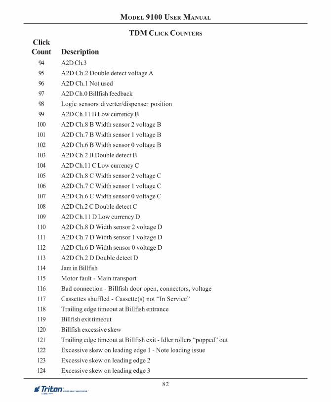


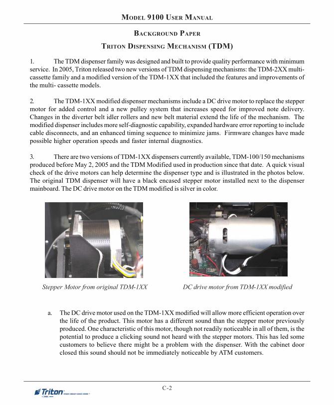


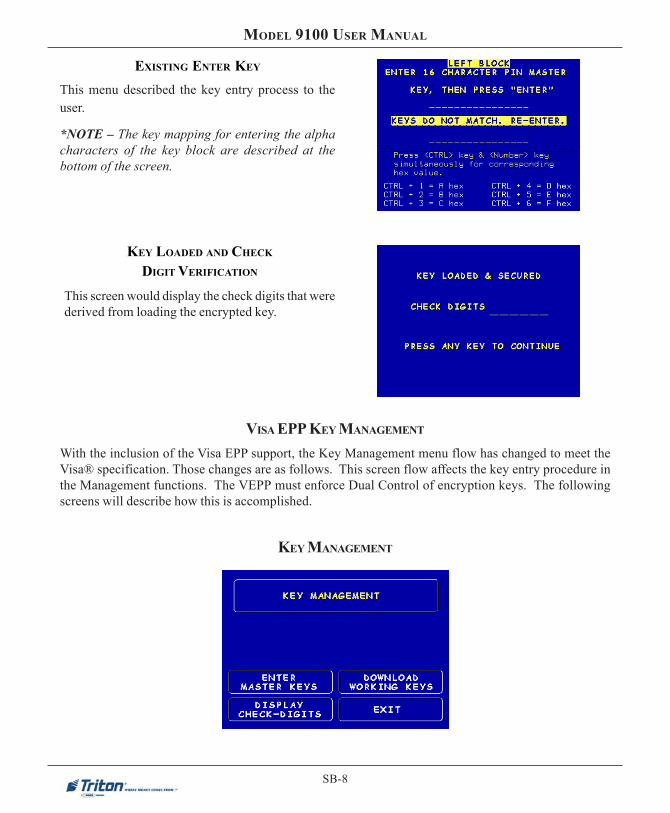


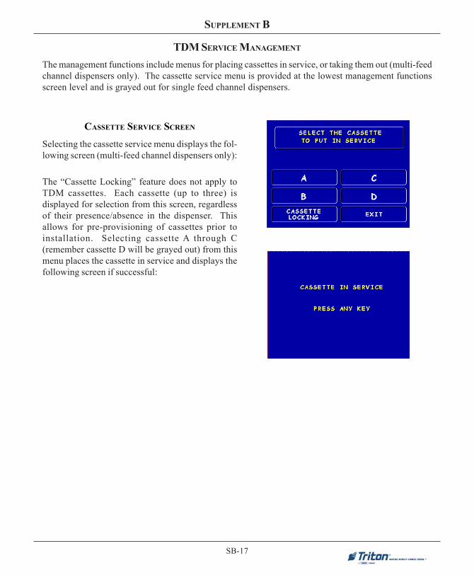
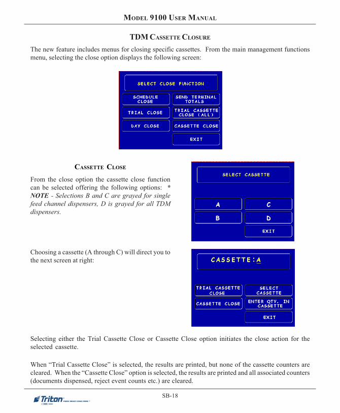


![Dion[1] 9100](https://static.documents.pub/doc/80x56/5549052eb4c90565458b4d76/dion1-9100.jpg)


