32
snot Apr. -May 1956 IN THIS ISSUE Converting 6 -Volt Auto Radios for 12 -Volt Operation Railroad Rad'io's First Decade NRI Alumni Association News VOL. 17 No. 2 www.americanradiohistory.com

snot
Apr. -May 1956
IN THIS ISSUE
Converting 6 -Volt Auto Radios for 12 -Volt Operation
Railroad Rad'io's First Decade
NRI Alumni Association News
VOL. 17
No. 2
www.americanradiohistory.com
A Plan for Today I WILL AWAKEN : With a smile brighten- ing my face; with reverence for this new day in my life and the opportunities it contains.
I WILL PLAN : A program which will guide me successfully past the many temptations and distractions of a busy day apd bring me one step closer to my goal of success.
I WILL WORK : With my heart always young and my eyes open so that nothing worth while shall escape me; with a cheer- fulness that overcomes petty irritations and unpleasant duties; with the purpose of my work always clearly in mind.
I WILL RELAX : When tired, so as to accumulate fresh en- ergy and live long enough to enjoy the success my work will bring.
I WILL PLAY : With the thought that today is my day, never to be lived over again once it is ended ; with relaxation and pure enjoyment as the only purposes of play; putting work and worldly worries out of mind for this short portion of my day.
I WILL RETIRE: With a weariness that woos sleep; with the satisfaction that comes from a day well lived, from work well done.
I WILL SLEEP: Weary, but content; with tomorrow a vision of hope.
J. E. SMITH, Founder.
www.americanradiohistory.com

NATIONAL RADIO -TV NEWS Louis L. Menne, Editor
H. L. Emerson, Associate Editor I. B. Straughn, Technical Editor
Published every other month by the National Radio Institute, 16th and U Sts., N. W., Washington 9, D. C. Sub- scription, $1.00 a year. Printed in U. S. A. Second -class mail privileges authorized at Washington, D. C.
Converting
6 -Volt Auto Radios
for
12 -Volt Operation
by
LEO M. CONNER NRI Consultant
MANY automobile manufacturers are now
producing cars with a 12 volt electrical sys- tem. A number of cars, made in Europe, have been brought into this country and some of these cars have 12 volt systems.
Because some people may purchase a radio sep- arately, the radio serviceman may be asked to install a 6 volt radio in a car with a 12 volt battery.
The problem is not difficult. There are four dif- ferent solutions to it. These solutions will be de- scribed and the advantages and disadvantages of each will be discussed. The serviceman should carefully consider all points before he under- takes an installation.
In most cases it is well to discuss the various
Leo M. Connor
angles with the customer as the costs vary widely. By making an intelligent explanation to your customer you may make more money on the job. Therefore, you should fully understand all four solutions and the advantages of each. If the decision is left up to you, choose the solu- tion which best fits the individual case.
Auto Radio Power Supplies
Before going into the conversion details it is advisable to review the methods of obtaining operating voltages from the dc source (battery) in the car.
A transformer cannot be used to increase a dc voltage. Therefore, some means of interrupting the do voltage must be provided. This is accom- plished by a device called a "vibrator."
Pace Three
www.americanradiohistory.com
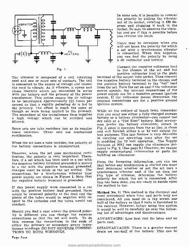
Fig. I.
The vibrator is composed of a coil, vibrating reed and one or more sets of contacts. The coil is connected to the source of voltage and causes the reed to vibrate. As it vibrates, it opens and closes contacts which are connected in series with the battery and the primary of the power transformer. This action causes the dc voltage to be interrupted approximately 115 times per second so that a rapidly pulsating dc is fed to the primary. The effect is much the same as though ac were being applied to the primary. The secondary of the transformer then supplies a high voltage which can be rectified and filtered.
Some sets use tube rectifiers just as do regular home receivers. Other sets use mechanical rectification.
When the set uses a tube rectifier, the polarity of the battery connections is unimportant.
However, when the set uses mechanical recti- fication, the polarity is very important. There- fore, if a set which has been used in a car with the negative battery terminal grounded is moved to a car with the positive terminal grounded, changes must be made in the set wiring. The connections for a synchronous vibrator type power supply are shown in Figure 1. Note that the negative battery terminal is grounded.
If this power supply were connected in a car with the positive battery lead grounded, there would be reversed polarity at the load and the plates of the tubes would be negative with re- spect to the cathodes and the tubes would not conduct.
Should you find a case where the ground polar- ity is different you can change the receiver connections so that the set will work. To do this, reverse the connections to the ends of either the primary or secondary power trans- former windings. DO NOT REVERSE CONNEC- TIONS TO BOTH WINDINGS.
Page Four
In some sets it is possible to reverse the polarity by pulling the vibrator out of its socket, rotating it 180 de- grees and plugging it back in the socket. Be sure to examine the vibra- tor and see if this is possible before you reverse the leads.
There may be occasions when you will not know the polarity for which a set with a synchronous vibrator is connected. When this happens, you can find the polarity by using a do voltmeter and battery.
Connect the negative voltmeter lead to the chassis of the set and the positive voltmeter lead to the plate
terminal of the output tube socket. Then connect the negative battery terminal to the chassis and the positive battery terminal to the "hot" lead from the set. Turn the set on and if the voltmeter moves upscale, the internal connections of the power supply are for a negative ground ignition system. If the voltmeter moves downscale, the internal connections are for a positive ground ignition system.
While on the subject of bench tests, remember that you must use either a fully charged storage battery or a battery eliminator -you cannot use dry cells or a "Hot Shot" battery. Most service- men prefer the battery eliminator, shown in Fig. 2, since it operates from the ac line, is clean and will furnish either 6 or 12 volt output for test purposes. This last feature is very desirable in carrying out operating tests after the set is modified for 12 volt operation. The Supply Division of NRI can supply the eliminator pic- tured in Fig. 2. (See page 9.) However, we cannot supply constructural information or parts for building an eliminator.
From the foregoing information, you can see that before any modification is started you must first determine whether or not the set uses a synchronous vibrator and, if the set does use this type of vibrator, determine the battery polarity for which the set is connected. After this has been done, you are ready to decide upon the method to use.
Method No. 1: This method is the cheapest and most economical when time and parts only are considered. All you need do is tap across one half of the battery so that 6 volts is furnished to the receiver. However, before using this system it would be well to carefully go over the follow- ing list of advantages and disadvantages.
ADVANTAGES: Low first cost for labor and no parts cost.
DISADVANTAGES: There is a greater current drain on one -half of the battery. This can be
www.americanradiohistory.com

Fig. 2.
minimized by periodically changing the bat- tery connections so that half of the battery is used one month and the other half of the bat- tery is used the next month. This would require careful attention by the car owner and the majority of car owners would neglect it.
The lack of attention would mean faster de- terioration of the battery and the expense of a new battery.
If the set uses a synchronous vibrator, it means that the internal connections must be changed and, in all cases, it will be necessary to insulate the set from the car and run a separate con- nection to the set chassis.
When all things are carefully considered, this method is most likely the least desirable from a long range viewpoint.
Method No. 2: This solution is second lowest in cost and removes one objection that is present in the first method.
A resistor can be used to drop the 12 volt battery output to the 6 volts needed to operate the re- ceiver. In order to determine the resistance needed, you must know the current drawn by the set when it is connected to a 6 volt source of power. In some cases this information might
be given on the set name plate or in the servic- ing information for the set.
If it is not given, you would need a dc AMMETER with a full scale range of 10 amperes or so. As an alternative, if you do not have an ammeter, you can open the negative high voltage return lead and connect a milliammeter in series with the lead. This will give the current drawn from the high voltage section. Be sure to use a meter range of 120 ma. or so.
Then total the filament current requirements of all of the tubes. This information can be obtained from a tube chart. This current is then added to the high voltage supply current. Since no power supply is 100 percent efficient you should add about 50 percent to the figure ob- tained by measurement and adding the tube filament currents. This will give a fair approxi- mation of the total current drawn by the set and the figure can be used to calculate the series resistance needed.
Let us assume that the radio draws 8 amperes from a 6 volt battery. The series resistor must drop the battery voltage from 12 volts to 6 volts or 6 volts. By Ohm's Law, R = ELI so R = 6 - 8 or .75 ohms. A 1 ohm resistor would give satisfactory operation in all cases where the battery was delivering full rated output. However, the resistor will dissipate considerable power and we must find the wattage rating needed. Since P = E x I, the power is 6 x 8 or 48 watts! For long life this should be doubled and the nearest standard resistance value is a 100 watt resistor.
Now let us list the advantages and disadvantages of this method.
ADVANTAGES: Reasonably low material cost and little labor required. Even current drain on battery and no necessity to charge battery con- nections after installation. If set uses synchro- nous vibrator, original polarity change, if needed, is all that is required. Set need not be insulated from car.
DISADVANTAGES: A resistor dissipating 48 watts of heat is not a desirable addition to the engine compartment. Mounting space so that resistor gets good ventilation may be hard to find.
In the case described, where the required wat- tage is 48 watts, it would be possible to use a standard 6 volt, 50 watt light bulb as a series resistance. These lamps are available in many rural communities and are shown in Sears mail order catalog. However, this solution can only be used where the power dissipation is near 50 watts and the bulb must be a 6 volt bulb. Of course, it is necessary to provide a socket for the bulb and the socket must be securely mounted.
Page Five
www.americanradiohistory.com

If this system is used, a spare bulb or two should be carried in the car because engine heat can cause short bulb life.
In many cases, either of the methods outlined above, may be the best all around solution.
6BA6 66E6 6BA6 6AT6 6AQ5
4 3
/\."/ 40n
2 WA T T
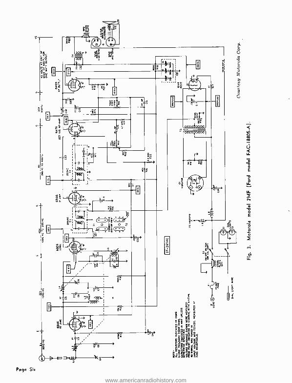
Method No. 3: This method is more costly than either of the other meth- ods that have been described. It requires a knowledge of set wiring and does require parts. In case this method is used, it should not be attempted without the diagram for the set and the diagram should be carefully studied before you start work. You should also make certain that all parts are on hand since the set is actual- ly changed over for direct 12 volt operation.
Figure 3 shows the schematic diagram for the Motorola Model 2MF receiver. The Ford number of this same set is FAC- 18805 -A. Let us examine this diagram and see how the set can be changed for 12 volt operation.
Notice that one filament connection is grounded at each tube socket. The "hot" filament connec- tion is taken through L6 from the set side of the ON -OFF switch. Further examination shows that there are 6 tubes in the set so a series -parallel connection of the filaments can be used to op- erate them directly from 12 volts. Before tube filaments can be operated in series they must have the same current requirements so let's check with a tube manual.
The 6BA6 tubes require .3 amp.; the 6BE6 tube requires .3 amp.; the 6AT6 tube requires .3 amp; the 6AQ5 tube requires .45 amp and the 6x4 tube requires .6 amp.
Now let's see how we can connect the filaments for 12 volt operation. The 6BA6 r.f. amp. and the 6BE6 convertor require the same current and can be connected in series. The 6BA6 I -F amp. and 6AT6 tube require the same current so they can be connected in series. The 6AQ5 and 6x4 have different current requirements but this does not mean they cannot be connected in series. However, it is necessary to shunt the 6AQ5 filament so that the filament and the shunt resistor will draw .6 amp. Since the 6AQ5 fila- ment requires .45 amp., the shunt current must be .6- .45 or .15 amp.
We can determine the shunt resistance by Ohm's Law, R = E /I. Then R = 6 ± .15 or 40 ohms. The wattage is 6 x .15 or .9 and if we double this for safety we have 1.8 watts. A 2 watt resistor or higher wattage rating would be satisfactory.
The .47 ohm resistor, shown as R 17 in Fig. 3, should be removed from the circuit. It is not used in the series -parallel filament connections.
Fig. 4.
6x4
Note that the vibrator and power transformer primary are also connected to the set side of the ON -OFF switch. Before rewiring the fila- ment circuit it is necessary to find the current drawn by the vibrator and power transformer and, in this case, the electro- dynamic speaker field. To find the current, disconnect all leads from the set side of the switch but the lead to L6. Then connect an ammeter in series with the leads you have disconnected and the point to which they were connected. Turn the set ON and measure the current.
Let us assume that the current is 5 amperes (entire set less the filaments). The series resis- tor is then 6 - 5 or 1.25 ohms. The wattage is 30 (5 x 6) and if we double this for safety we need a 60 watt resistor. Most likely the resistor would need to be mounted outside the set for ventilation and a 50 -watt resistor would be satis- factory.
It would also be possible to bring out leads to a 6 volt, 25 or 30 watt lamp bulb where the con- ditions given apply.
When you have finished all calculations, you are ready to rewire the circuits. Fig. 4 shows how the filament circuit wiring should be rearranged. The filament terminal numbers are the same as shown in Figure 3.
The changes in other wiring are as shown in Figure 5.
When these changes have been properly made the set performance should be the saine as for a 6 volt source.
ADVANTAGES: No power lost in filament cir- cuit because of series -parallel connection. Only two new parts required.
DISADVANTAGES: Heat dissipated by large wattage resistor. Resistor should be outside cabinet which may make installation difficult.
Method No. 4: This method calls for complete conversion. It is most expensive of all for both parts and labor.
In this method the filaments are rewired just as in Method No. 3.
Then a new transformer and new vibrator de-
Page Seven
www.americanradiohistory.com
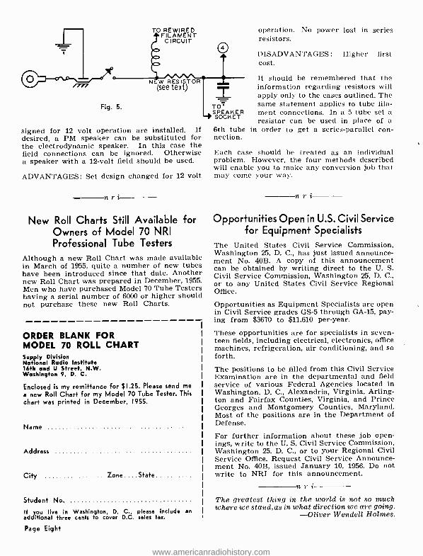
TO REWIRED FILAMENT
CIRCUIT
Fig. 5.
N W RESI TOR (see tex t)
signed for 12 volt operation are installed. If desired, a PM speaker can be substituted for the electrodynamic speaker. In this case the field connections can be ignored. Otherwise a speaker with a 12 -volt field should be used.
ADVANTAGES: Set design changed for 12 volt
nri
New Roll Charts Still Available for Owners of Model 70 NRI Professional Tube Testers
Although a new Roll Chart was made available in March of 1955, quite a number of new tubes have been introduced since that date. Another new Roll Chart was prepared in December, 1955. Men who have purchased Model 70 Tube Testers having a serial number of 6000 or higher should not purchase these new Roll Charts.
ORDER BLANK FOR MODEL 70 ROLL CHART Supply Division National Radio Institute 16th and U Street, N.W. Washington 9, D. C.
Enclosed is my remittance for ;1.25. Please send me
a new Roll Chart for my Model 70 Tube Tester. This chart was printed in December, 1955.
Name
Address
City Zone State
Student No.
If you live in Washington, D. C., please include an additional three cents to cover D.C. sales tan.
Page Eight
TO' SPEAKER SOCKET
6th tube nection.
operation. No power lost in series resistors.
DISADVANTAGES: Higher first cost.
It should be remembered that the information regarding resistors will apply only to the cases outlined. The same statement applies to tube fila- ment connections. In a 5 tube set a resistor can be used in place of a
in order to get a series -parallel con-
Each case should be treated as an individual problem. However, the four methods described will enable you to make any conversion job that may come your way.
n r i
Opportunities Open in U.S. Civil Service for Equipment Specialists
The United States Civil Service Commission, Washington 25, D. C., has just issued announce- ment No. 40B. A copy of this announcement can be obtained by writing direct to the U. S. Civil Service Commission, Washington 25, D. C., or to any United States Civil Service Regional Office.
Opportunities as Equipment Specialists are open in Civil Service grades GS -5 through GA -15, pay- ing from $3670 to $11,610 per -year.
These opportunities are for specialists in seven- teen fields, including electrical, electronics, office machines, refrigeration, air conditioning, and so forth.
The positions to be filled from this Civil Service Examination are in the departmental and field service of various Federal Agencies located in Washington, D. C., Alexandria, Virginia, Arling- ton and Fairfax Counties, Virginia, and Prince Georges and Montgomery Counties, Maryland. Most of the positions are in the Department of Defense.
For further information about these job open- ings, write to the U. S. Civil Service Commission, Washington 25, D. C., or to your Regional Civil Service Office. Request Civil Service Announce- ment No. 40B, issued January 10, 1956. Do not write to NRI for this announcement.
n r i
The greatest thing in the world is not so much where we stand,as in what direction we are going.
-Oliver Wendell Holmes.
www.americanradiohistory.com

New Electro -Voice Centurion Corner Folded -Horn Enclosure and 4 -Way
Loudspeaker Systems
New CENTURION corner folded -horn enclosure and 4 -way loudspeaker systems have been intro- duced by Electro- Voice, Inc., Buchanan, Mich- igan. The CENTURION provides design features of the Electro -Voice Georgian, but on a smaller scale at more modest cost.
The enclosure fully utilizes the walls at the corner of the room to extend bass reproduction down below 35 cps. When integrated with a matched E -V separate speaker system, the CENTURION provides a highly efficient 4 -way reproducer. Multiple driver and crossover points divide the audio spectrum into four sections with smooth transition from one to another for clean, distortion -free reproduction and over- all musical balance. Level controls permit ad- justment of "presence" and "Brilliance" to bal- ance room acoustics.
Size is 42 in. high, 29 in. wide, 221/2 in. deep. Net price in Mahogany is $157.80, and in Korina Blonde $166.80.
The CENTURION is also available with complete factory -assembled 4 -way speaker system, in CENTURION IV at $297.00 and $306.00 and in SENIOR CENTURION IV at $375.00 and $384.00.
For easy "Do- it- Yourself" CENTURION Model 117 and Model 105 separate 4 -way package of driver components are available at $139.20 and $208.50, without enclosure. Enclosure kit is $79.00.
For complete information, write to Electro- Voice, Inc., Buchanan, Michigan.
nri Radio Station WGAT, of Utica, New York has an opening for a man with a first class radio- telephone license. Forty hour week. If interested, write direct to Fred Harrington, Chief Engineer, above address.
NRI Offers "A" Battery Eliminator For Testing Auto Radio:,
PROVIDES 6 VOLTS & 12 VOLTS D.C.
TYPE 610C -ELID -Rated output 6 volts at 10 amperes continuous or 12 volts at 6 amperes con- tinuous. Either output obtainable by means of simple output terminal switching arrangement.
Equipped with Full -Wave Dry Disc Selenium Rectifier, Assuring Noiseless, Interference -Free Operation and Extreme Long Life and Reliabil- ity. Can also be used as a battery charger.
On -Off Switch, 8- Position Voltage Control, Meters, Fuse Protection, Rubber Mounting Feet, 6 -ft. All- Rubber Cord Set, and Cabinet of heavy gauge metal having attractive grey -ham- merloid finish. Size 61/2" x 91,2" x 81/2 ".
Only $39.95 Shipping weight, 22 lbs. By Express, collect. In- structions and warranty included.
ORDER BLANK-- - - - - -. National Radio Institute, Supply Division, 16th and U Streets, N.W., Washington 9, D. C.
I enclose $39.95 (money order, check or bank draft). Send me the above "A" Battery Eliminator. LI Please send information concerning vime pay-
ments.
Name Student No.
Address
City Zone State
Express Office If you live in Washington, D. C., add 2% for D. C. Saps Tax.
Page Nine
www.americanradiohistory.com
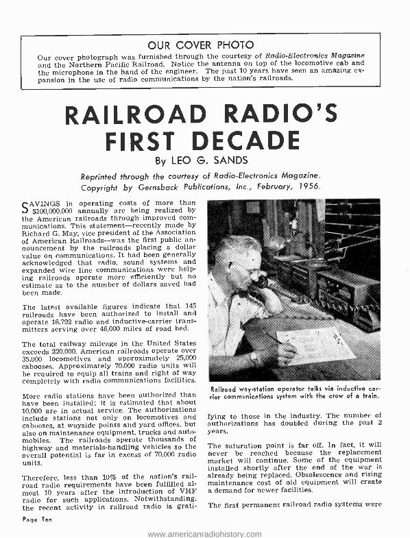
OUR COVER PHOTO Our cover photograph was furnished through the courtesy of Radio- Electronics Magazine and the Northern Pacific Railroad. Notice the antenna on top of the locomotive cab and the microphone in the hand of the engineer. The past 10 years have seen an amazing ex- pansion in the use of radio communications by the nation's railroads.
RAILROAD RADIO'S FIRST DECADE
By LEO G. SANDS
Reprinted through the courtesy of Radio -Electronics Magazine. Copyright by Gernsback Publications, Inc., February, 1956.
SAVINGS in operating costs of more than $100,000,000 annually are being realized by
the American railroads through improved com- munications. This statement -recently made by Richard G. May, vice president of the Association of American Railroads -was the first public an- nouncement by the railroads placing a dollar value on communications. It had been generally acknowledged that radio, sound systems and expanded wire line communications were help- ing railroads operate more efficiently but no estimate as to the number of dollars saved had been made.
The latest available figures indicate that 145 railroads have been authorized to install and operate 16,792 radio and inductive- carrier trans- mitters serving over 46,000 miles of road bed.
The total railway mileage in the United States exceeds 220,000. American railroads operate over 35,000 locomotives and approximately 25,000 cabooses. Approximately 70,000 radio units will be required to equip all trains and right of way completely with radio communications facilities.
More radio stations have been authorized than have been installed; it is estimated that about 10,000 are in actual service. The authorizations include stations not only on locomotives and cabooses, at wayside points and yard offices, but also on maintenance equipment, trucks and auto- mobiles. The railroads operate thousands of highway and materials -handling vehicles so the overall potential is far in excess of 70,000 radio units.
Therefore, less than 10% of the nation's rail- road radio requirements have been fulfilled al- most 10 years after the introduction of VHF radio for such applications. Notwithstanding, the recent activity in railroad radio is grati-
Page Ten
Railroad way -station operator talks via inductive car- rier communications system with the crew of a train.
fying to those in the industry. The number of authorizations has doubled during the past 2
years.
The saturation point is far off. In fact, it will never be reached because the replacement market will continue. Some of the equipment installed shortly after the end of the war is already being replaced. Obsolescence and rising maintenance cost of old equipment will create a demand for newer facilities.
The first permanent railroad radio systems were
www.americanradiohistory.com

Communications system in caboose.
installed in classification yards where their economic advantages were most apparent. Today, the emphasis is on main lines where the move- ment of freight can be handled much more efficiently with rapid communications. Approxi- mately 75% of new installations are for road use.
Equipping trains with radio is not a new idea. Way back in 1914 the Delaware, Lackawanna & Western Railroad experimented with spark transmitters to determine the practicability of communicating between wayside points and moving trains. In 1936 RCA worked with the Pennsylvania Railroad on caboose -to- engine com- munications.
Ten years ago, VHF radio in the 152 -162 me band was tried out in railroad applications and was found to be very satisfactory. The low power requirements, short antenna length, freedom from noise, limited and controllable range and multiple reflection characteristics combine to make VHF ideal.
The military SCR -522 VHF transmitter- receiver unit designed for airborne applications was modified and pressed into service in experi- mental installations. When it had been deter- mined by field tests that VHF was the answer, several manufacturers designed and started building two -way equipment for railroad appli- cations. One of the earliest units used AM and provided excellent performance but was abandoned in favor of an FM unit because of the popular demand at that time for frequency - modulated systems.
The first permanent railroad radio authoriza- tions were granted by the FCC to the Denver & Rio Grande Western Railroad and the Baltimore & Ohio Railroad. These were followed shortly by grants to others, including the Santa Fe
Courtesy RCA A portable two -way radio used by car
inspectors and flagmen.
System; Burlington Lines; Milwaukee Road; Elgin; Joliet & Eastern; Gulf Mobile & Ohio; Central of Georgia; Northern Pacific; Seaboard Air Line and the Delaware, Lackawanna & Western Railroad.
In 1945 the Baltimore & Ohio Railroad conducted tests between Baltimore and Washington to de- termine the practicability of using radio com- munications between wayside stations and fast trains in areas of high traffic. The following year the Seaboard Air Line Railroad tried VHF radio for point -to -train communication between Atlanta and Birmingham. It was found that a portable walkie- talkie with less than 1 /10 watt rf power output operated inside of a steel rail- road coach provided excellent communication with a fixed station 8 miles away. However, this does not mean that the low -power unit will pro- vide such excellent range under other than freak or ideal conditions.
Several manufacturers spent considerable time and money during the early years of railroad radio in developing suitable special equipment and demonstrating that radio was a reliable means of train communication and that its economic advantages were worthy of considera- tion.
Its wide -scale application did not occur imme- diately and for very justifiable reasons. The railroads first had to be convinced that radio could be justified economically in the face of long -established operating and labor policies. Secondly, they had to be assured that the equip- ment would perform adequately with reason- able maintenance and that the manufacturer would remain in the railroad radio business on a permanent basis to stand by his equipment. The railroads listened and watched several com-
Page Eleven
www.americanradiohistory.com
WAYSIDE TELEGRAPH &TELEPHONE LINES
WAY STATION EQUIPMENT
COUPLED INDUCTIVELY OR
CAPACITIVELY TO WIRES
1
CABOOSE LOOP ANT
o
ERIE ERIE
Lo10 w.a,'oM0:ótWó o.Mo_o vßó= ónoo =og*o cLITamsró o.._ NYC
DIESEL LOCOMOTIVE
NA
CRNJ
/LOOP ANT
ERIE r1D l \Y
CONNECTED TO RAIL TRUCK RADIO UNIT EQUIPMENT
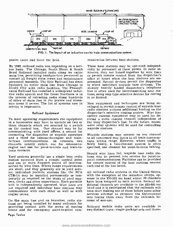
FIG. I. The layout of an inductive- carrier train communications system.
panies enter and leave the field.
By 1949, railroad radio was expanding on a seri- ous basis. The Chicago, South Shore & South Bend Railroad installed radio along its entire main line, permitting headquarters personnel to contact all freight train crews and maintenance personnel instantly. The Erie Railroad has since equipped its entire main line from Chicago to Jersey City with radio facilities. The Pennsyl- vania Railroad has installed a widespread induc- tive radio system and the Great Northern is in the process of extending radio along hundreds of miles of main line in the prairie and moun- tain areas it serves. The list of systems now in service is impressive.
Railroad Equipment
To meet operating requirements the equipment in a locomotive may have to operate on two or three channels which are selected by a switch on the control box. One channel may be for communicating with yard offices, a second for contacting the dispatcher or wayside operators and a third for caboose -to- engine and train - to -train communications. In cabooses, two channels usually suffice, one for caboose -to- engine and one for point -to -train and train -to- train contacts.
Yard systems generally use a single base radio station operated from a remote control point and one or more dispatch points all intercon- nected by wire lines. Where range requirements are short, and they generally are in yard serv- ice, individual portable stations like the RCA CTR -1A may be installed permanently or tem- porarily as required on the desks of yard mas- ters, clerks and other supervisors. Each portable unit is independently operated. Wire lines are not required and individual base stations may communicate with each other as well as with engine crews.
On the main line and on branches, radio sta- tions are being installed by many railroads for providing contact with the crews of moving trains and for emergency point -to -point com-
Page Twelve
munication between base stations.
These base stations may be operated independ- ently by personnel at these points. In some in- stances, they are linked together by wire lines to permit remote control from the dispatcher's office at hours when the base stations are un- attended. Special devices permit the dispatcher to select individual wayside base stations. The already heavily loaded dispatcher's telephone line is often used for interconnecting base sta- tions, using step type selective devices for cutting in as desired.
New equipment and techniques are being de- veloped to permit remote control of wayside base radio stations without additional loading on the dispatcher's selective ringing system. Wire line carrier current equipment may be used for de- riving a radio control channel independent of the busy dispatcher's line. In the future, micro- wave relay systems will be used for controlling wayside stations.
Wayside stations may operate on one channel so all concerned may listen to all train conversa- tions within range. However, where traffic is fairly heavy, a two -channel system is often specified, one channel for point -to -train talking.
Should wire lines fail, wayside base radio sta- tions may be pressed into service for point -to- point communications. Facilities can be provided for remote control of the base stations nearest each end of the line break.
All railroad radio systems in the United States, with the exception of the inductive setups, op- erate in the 152 -162 me band where 39 channels have been assigned to such service. Several ad- ditional channels are available in the 450 -460 me band and it is anticipated that the railroads will soon start making use of these before some other services attempt to pressure the Government into taking them away from the railroads be- cause of non -use.
Railroad mobile radio units are available in two distinct types: single- package sets and three-
www.americanradiohistory.com

package combinations. In the single -package type, the transmitter, receiver and power sup- ply chassis are bolted together and enclosed in a single metal cabinet. The three -package com- binations consist of a separate transmitter, re- ceiver and power supply in individual drawer type enclosures.
FM is universally used. Transmitters and re- ceivers are fixed -tuned and crystal -controlled. Transmitter power output ratings run from 10 to 30 watts although 60 -watt units are available. Receiver sensitivity is in the order of 1 micro- volt for 20 db of quieting.
Inductive- carrier train communications systems (Fig. 1) which operate on frequencies between 75 and 200 kc depend upon wayside telephone wire lines to act as conveyors of the signal. Wayside stations are directly coupled to the wire lines whereas mobile units are coupled inductively (the transmitter feeds current into the rails, inductively energizing nearby wire lines). A large loop antenna is generally used on cabooses and locomotives.
The main advantage of inductive -carrier systems is their extended range far in excess of that obtainable with VHF systems. However, induc- tive- carrier mobile units require more power than VHF radio and are more costly.
More than 90% of train and yard engine com- munications stations use VHF radio; inductive - carrier accounts for less than 10 %. Both sys- tems provide excellent communications.
Most diesel -electric locomotives have 64 -volt storage batteries kept charged by an auxiliary generator. Some, however, use 32- or 110 -volt batteries. Radio equipment in a diesel locomotive is powered by the battery and installed in a shock -mounted rack in the nose of the locomo- tive, under a seat or in the engine compart- ment, depending upon the type of locomotive or the preference of the railroad. The available do is converted to ac by a vibrator type inverter, rotary converter or motor generator set. Most radio equipment (Fig. 2) used in locomotives is designed to operate from an ac source although one manufacturer has introduced a unit with a vibrator type power supply for operation direct- ly from a 64 -volt battery source.
Two types of axle- driven generators are widely used: do generators and ac generators with rectifiers. The do generator is a standard device widely used in passenger -car service. The al- ternator- rectifier system is newer and popular in caboose applications. It consists of an alterna- tor with a rotating field which supplies three - phase ac to a selenium rectifier which in turn furnishes do to the battery and the load. The use of air -driven generators for battery charg- ing and powering radio equipment has been tried
SPKR
ANT
r,COA&
off -
I - - NIT TER VOL CONT
DC TO ÿC INVERTER
D
C
ó
NÓÑSMIKÉ ORAHAN[SMET M
4
RY
MIKE
^I TRAIN BATT RY I
FIG. 2. Bask requirements for locomotive or caboose communications.
by the Rock Island Lines. Air is obtained from the brake system with safety devices preventing brake trouble.
The caboose presents a problem because it is seldom provided with an electrical system. Thus, when installing radio, it is necessary to provide electric power. Internal combustion en- gine driven generators were tried but most have been discarded in favor of axle- driven generator and battery systems.
Cabooses are being equipped with 12- or 32 -volt electrical systems. A few have been fitted with 6-volt battery systems but the slightly increased cost and operating advantages of 12 -volt setups have caused most railroads to specify the higher voltage. A caboose electrical system is similar to that of a conventional passenger coach. A generator is driven by the car axle through a belt drive system.
A 12 -volt system is generally used when only the radio equipment and a minimum, if any, of lights are to be operated. When the load re- quirements are greater, 32 -volt systems are more desirable in caboose applications.
With a 12 -volt electrical system, the radio equip- ment used usually operates directly from a 12- volt dc source. When 32 volts dc is available, an inverter is generally used with ac- operated radio equipment.
Portable pack sets are being used in cabooses in lieu of regular heavy -duty railroad radio equipment to avoid the installation of elec- trical power systems. The conductor may call the engineer with his pack set but, because of short battery life, he does not monitor trans- missions from the locomotive. Furthermore, pack sets in cabooses will not permit wayside stations to call the conductor directly. In- stead, the engineer is usually alerted by radio, and by whistle or other signals the con- ductor is notified to turn on his radio. How -
Page Thirteen
www.americanradiohistory.com
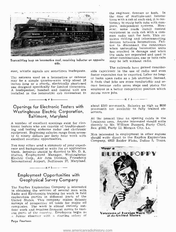
Transmitting loop on locomotive roof, receiving inductor on opposite side.
ever, whistle signals are sometimes inadequate.
The antenna used on a locomotive or caboose may be a simple quarter -wave whip about 18 inches long or a sturdy, electrically shortened one designed specifically for limited clearances. A loudspeaker, handset and control unit are installed in the locomotive cab convenient to r
Openings for Electronic Testers with Westinghouse Electric Corporation,
Baltimore, Maryland
A number of excellent openings exist for elec- tronic testers who are capable of trouble- shoot- ing and testing airborne radar and electronic equipment. Beginning salaries range from seven- ty to ninety dollars per forty hour week with excellent overtime opportunities.
You may either send a summary of your experi- ence and background or write for an application blank. Inquiries should be directed to Mr. D. R. Statter, Employment Manager, Westinghouse Electric Corp., Air Arm Division, Friendship International Airport, Baltimore 27, Maryland.
nri
Employment Opportunities with Geophysical Survey Company
The Rayflex Exploration Company is interested in obtaining the services of several men with Radio and Electronics training for work in field exploration parties in different parts of the United States. This company makes Seismic surveys of prospective oil lands for major oil companies. The work is almost entirely out- door work and requires frequent moves to vari- ous parts of the country. Employees begin as a Junior observer with a starting salary of
Page Fourteen
the engineer, fireman or both. In the case of multiple -unit locomo- tives with a cab at each end, it is cus- tomary to equip both cabs with com- plete, independent systems. How- ever, some roads install control equipment in each cab with a com- mon radio unit for both. This re- quires cabling and interconnecting devices between locomotives. Fail- ure to disconnect the connectors when uncoupling locomotive units has resulted in damage and when the units are separated and used in other combinations, one or both cabs may be left without radio.
The railroads have gained consider- able experience in the use of radio and even faster expansion can be expected. Labor no long- er looks upon radio as a job snatcher. Instead, it finds that jobs are more comfortable and se- cure because radio saves steps and places the employer in a better competitive position which means more jobs.
nri about $300 per- month. Salaries as high as $650 per -month are available to fully trained ob- servers.
At the present time an opening exists in the Louisiana area. Anyone interested should write directly to Mr. William Bussard, Party Chief, Box #662, Party 12, Morgan City, La.
Men interested in employment in other regions should write direct to the Rayflex Exploration Company, 6923 Snider Plaza, Dallas 5, Texas.
Wear a .
1U IDID - FOP UP i
Veterans of Foreittn Wars rlihetailed Stales
www.americanradiohistory.com

SCIENCE QUESTION BOX By Scientists of the General Electric
Company
Q: Why can't large springs be put in automobiles and wound up so as to provide power when they unwind? A: Springs are often used to drive toy automo- biles, and they have been suggested for use in full -sized cars. In fact, around 1500, Leonardo da Vinci proposed such a spring- driven vehicle. However, the amount of energy that can be stored in a spring is very small compared to other means of storing energy now available. In units of foot -pounds (the amount of energy required to raise a weight of one pound one foot) a spring can only store about 32 foot - pounds for every pound of its own weight. A storage battery, of the type used in automobiles, can store 2840, compressed gas 14,509 and a spin- ning flywheel 22,600 ft. lbs. per lb.
Q: Do gold fish need air in their water? A: Yes. Fish "breathe" as water passes through their gills, giving up dissolved oxygen. Although water consists of a chemical combination of hy- drogen with oxygen, this is not available to them. If well water is used in an aquarium it may contain too little dissolved oxygen. In that case it might help to let the water stand in a bowl for a day or two, perhaps pouring it from one bowl to another several times, or air may be bubbled through. This will cause the water to absorb oxygen.
Q: Please tell me something about the planet Pluto. A: Pluto, which is generally farther from the Sun than any of the other eight major planets, was discovered in January, 1930, by Clyde Tom - baugh, with the aid of photographs taken at the Lowell Observatory, Flagstaff, Arizona. It would have to be increased in brightness some 4000 times in order to be just barely visible to the naked eye, so it can only be observed with large telescopes. Since it is so far out from the Sun and gets so little light it was named after the god of the underworld. It revolves around the Sun in 248 years, at an average distance of 3,- 670,000,000 miles, about 40 times as far as the Earth. Its orbit is very elliptical so it can come as close to the Sun as 2,761,000,000 miles, which is nearer than Neptune. Its diameter is not known exactly, although one measurement a few years ago put it at about 3550 miles.
Q: What is the largest snake? A: There is some dispute among zoologists as to whether this title is held by the reticulated python, which is found in India, Malaya and sur- rounding countries, or the anaconda of South
America. The former is known to reach a length of 32 feet, while specimens of the latter over 30 feet, have also been reported. However, the ana- conda is much more bulky than the relatively slender python, and for the same length would weigh considerably more.
Q: Does the gasoline in an automobile engine burn or explode? A: What happens to the mixture of air and gaso- line vapor in the cylinder of an automobile en- gine is usually considered an explosion, but there is no sharp dividing line between explosion and fast -burning. The explosion of gunpowder is really a very rapid burning. However, high ex- plosives, like nitroglycerin, undergo detonation. A shock wave travels through the explosive mass at high speed (several miles per second), and it all explodes practically instantaneously. Some- times detonation occurs in an automobile engine cylinder, but this is undesirable, as it causes "knocking," with loss of power.
Q: Is there anything I can do to replace a wool sweater which shrank and became as stiff as cardboard after I washed it 4; hot water? A: Unfortunately, no. The great shrinkage which occurred resulted from a "felting" effect and the fibers have become irreversibly en- tangled. There are some wool yarns now avail- able which have been treated so they will not felt and garments of this type may be washed more easily than the older yarns.
Q: I recently varnished the inside of a wooden bucket that I wish to use for cookies, but the varnish odor persists. What can I do? A: It would probably have been better to have used white shellac, rather than varnish. To re- move the varnish, a paint and varnish remover may be used. These usually contain wax, so any that remains should be removed with denatured alcohol. Let the bucket dry thoroughly to re- move the alcohol odor. Then use commercial white shellac, thinned with equal parts of de- natured alcohol. Apply one coat, let it dry for 24 hours and apply another. This should leave no odor that would affect the cookies.
Q: Can scientists rearrange atoms of metals to make them stronger amd better? A: Yes, much of the work of metallurgists is es- sentially in doing this very thing, mostly by spe- cial heat treatments or mechanical working. All metals consist of atoms arranged in a more or less regular lattice to form crystals, and the properties of the metals depend on what atoms are present and how they are arranged. In this way they have produced new metals and alloys (which are mixtures of metallic elements) that are stronger, or can withstand higher tempera- tures, than any previously made. These have made possible highly efficient modern steam and gas turbines as well as many other devices.
Page Fifteen
www.americanradiohistory.com

NRI Training Leads to "Extra" Cash
And New Employment Opportunities
Made $500
"Extra" First
Year After
Graduation
"I started to repair Radios after my fifteenth lesson. When I started doing minor Television repairs, I remember how interesting it was and the satisfaction I had when I finished a tough one.
"You can learn a lot from reading books but there isn't anything to take the place of actual experience. That is where the NRI kits come in handy. A fellow sure does get a lot of experi- ence from them.
"I now have a spare -time business of my own in addition to my regular job and am doing very well. Made about $500 extra my first year and am sure I will do a lot better. I am now doing more TV work than Radio."
MYRON THEETGE 9 E. 39th St. Covington, Ky.
n r 2
Enthusiastic About
Now Department
Foreman with
Remington Rand On
Univac Computers
"When I started your course, I had no previous knowledge of electronics. I was employed by Remington Rand, of Ilion, N. Y., as a machine operator. Since taking your course, I have gone up very rapidly in the company.
"I was taken from machine work and given training on electronic computers. After work- ing as an electronic technician on computers, I was made Department Foreman in the assembly and test department for the models 60 and 120 Univac. I believe my position with the company was made possible by taking NRI training, and I never fail to recommend it to anyone interest- ed in any phase of electronics. I can't thank NRI enough."
LEON H. HAND RFD 1 West Winfield, N. Y.
n r i
Own Full -Time Radio -TV Sales and Service Business
Page Sixteen
"About the time I finished my course I opened a shop of my own and started repairing Radios by the dozens. I later held a position as parts and service manager for an RCA distributor. I then worked for nine months on the engineering staff of a Television station.
"I have now opened another Radio -TV business of my own, which I like best of all. I handle the RCA Victor line of home receivers and sell just any kind of electronic equipment and service that the public buys."
F. B. ROBERTS 6140 Jocelyn Hollow Rd. Nashville, Tenn.
www.americanradiohistory.com
Serviceman
For
Sears
Roebuck
"I am employed with the service department of Sears Roebuck. After eight months, I am very well pleased with my job. We service all makes of Radio and Television sets.
"I have my spare time shop at home, also, and have all the work I can take care of at night and on my day off. I have done as much as $300 in business in a month just working nights and Mondays.
"Yours is a fine school and I owe much of my success to your basic course in Radio -TV."
LOGAN P. STOWE 905 Madison Ave. Winston -Salem, N. C.
Started On
Full -Time Jcb
Before Graduation
From NRI
"I am employed in a full -time job as a Radio and Television serviceman for Hudson Battery and Electric Company. We sell Zenith and Magna- vox, and have the most complete repair shop in our town. We also service two -way communica- tions Radio and micro -wave equipment. I start- ed on this job after I had completed a little over one -half of the NRI course.
"I think your course is fine. It certainly meas- ured up to my expectations. If you really get all there is out of the course you don't need any other training."
ERNEST E. JONES 200 N. Vine St. El Dorado, Kansas
n r i
Shop is Netting an Average of $ 100 per Week
"I enrolled in the NRI course at the age of 59. Six months later I was taken to the hospital completely paralyzed with Polio. In spite of this I continued my studies and after two months in bed was sent home in a wheel chair.
"I am enclosing a picture showing me at work in my shop. At the present time my shop is net- ting me an average of $100 per week, and I am sure that I could double this if I went into busi- ness full time."
EDWARD L. RAWLINS 802 N. Sheridan Rd. Tulsa, Okla.
As space permits, from time to time, we like to devote a page or two in NR -TV News to short suc- cess stories such as above. They are taken from testimonial letters we have on file. Photographs and letters of this kind are always greatly appreciated by us. We feel we should pass them on to our readers for the inspiration to be gained from a reading of them.
Page Seventeen
www.americanradiohistory.com

Boyne P404/ems al
ea/a TeIeotia#i By JAMES P. TATE, JR.
Chief Technical Editor, NRI Instruction Material.
COLOR Television development started even before black and white Television was in its
commercial stages. Nearly all of the early work- ers in the field of Television felt that black and white was only one step towards full color. In 1950 the FCC approved a set of standards for a field sequential color system. This system, which used a rotating color wheel in front of the pic- ture tube, was quite unsatisfactory. Very little was ever done with this system and it never went into full commercial usage.
The color wheel system was obviously so poor that an organized industry -wide effort was made to develop a more practical and satisfactory sys- tem of color televising. This research campaign was under the direction of the National Televi- sion System Committee. The NTSC is an asso- ciation of Engineers and Scientists interested in the development of Television and its members include representatives of many of the companies engaged in the manufacture of Television equip- ment. This committee studied the over -all prob- lem of color Television and selected the fields in which additional investigation was necessary. These fields were further broken down and separate problems were parcelled out to the var- ious members. In this way needless duplication of efforts was avoided. This also assured that all necessary investigations would be made.
This effort lead to the adoption by the FCC in December of 1953 of a system of color Television which is termed the NTSC compatible color sys- tem. While the efforts of this committee solved the problems of color Television from a purely technical viewpoint they did not however over- come the problem of relatively high cost of the receivers. Because of this high cost there are to- day very few color Television sets as compared to the number of black and white sets being Page Eighteen
James P. Tate, Jr.
used in homes throughout the United States.
Adding color to the Television signal resulted of course in much more complicated Television re- ceivers and required the use of a new type of picture tube. The increased complexity of the receivers and the difficulties of manufacturing the picture tube have made present day receiv- ers very expensive. These sets not only cost three to four times the price of present day black and white receivers but there is very little oppor- tunity to use them for color pictures.
Just as color increased the cost and complexity of the receivers so it greatly increased the cost of producing Television shows. The camera equipment is much more complicated and expen- sive than that required for black and white. Considerably more maintenance time is required on this equipment and more personnel are re- quired in order to operate it. The cost is so high that it is impractical for small stations to install their own color televising equipment. Even for large network productions the cost is so very high in proportion to the number of receivers in the field, which are capable of receiving the show, that advertisers are quite reluctant to in- vest the extra money necessary for a color Tele- vision show. The majority of large color broad- casts on the networks have been financed as much for the prestige of the sponsor as for the actual advertising worth.
Each of the last two years have seen lower aver- age receiver prices and more color Television shows on the air. Nevertheless acceptance by the public of color Television receivers has been quite slow. The increase in the number of sets in the hands of the public has been much slower than the increase in black and white sets during the years 1947 and 1948. These years In black
www.americanradiohistory.com
and white Television are quite comparable to the present stage of color development.
In spite of the present slow growth, no service- man can afford to ignore color. Each year sees more servicemen encounter their first color Television installation or service call. Some of these men are ready for the job, others are not. Those who were ready received well deserved credit and a better professional reputation in their communities. Those who were not ready had a tough time with their job, but are not like- ly to be caught short the second time. There is no longer any excuse for a serviceman to be completely unprepared for his first color service call. To be sure he cannot be as familiar with a color receiver as with a black and white set. The number of receivers that has been produced is small and are well scattered throughout the country. The opportunities for the individual serviceman to experiment with controls and ad- justments are few. However most servicemen have ample opportunity to learn the similarities and differences between black and white and color TV receivers. When the problem is ap- proached in this way the serviceman will find that the similarities are very great and the dif- ferences are more in numbers of circuits than in circuit types. The big exception to this of course is in the picture tube itself.
Black and white receivers today average four- teen tubes and a picture tube. The color set will have between twenty -six and thirty -five receiv- ing type tubes plus the large color picture tube. It is obvious from these figures that the color set is much more complicated than the black and white. Still when you realize that there are three separate video signals to be handled in color instead of one, the increase in tube types does not seem to be too great. All of the circuits with which the serviceman has become familiar in his black and white work appear in color re- ceivers. The front end and i -f strips and sound channels are almost identical with those of monochrome receivers. New circuits are used to separate the color signals and to channel them to the picture tube. None of these new circuits is by itself a difficult circuit to understand. The first look at a color receiver schematic diagram gives the impression of terrific complexity. Part of this is caused by the names given the indi- vidual stages required in color. These names, of course, are new to the average serviceman. However by taking each circuit by itself and studying it, it is possible to see the logical order in which these circuits are put together and used. Each circuit by itself will be quite easy to understand. In this way the entire problem becomes one of not too great difficulty. By this I do not mean to say that color is as easy to service as black and white. It is not. But color TV servicing is certainly within the scope of knowledge of servicemen.
One of the first things the serviceman will notice in working with color receivers is that each part and circuit is much more critical of adjustment and much more sensitive to changes than the comparable circuits in a black and white receiver. This starts right at the antenna. The antenna must be very carefully oriented to avoid ghosts and noise pickup. The transmission line must be of high quality for the saine rea- sons. The front end tuner must have a broader response and the input impedance should not change with changes in age bias. It is necessary to provide a better match between the transmis- sion line and the tuner. The i -f of the receiver must be broader in frequency and flatter and its pattern should not be tilted or changed by changes in bias. The video amplifier will have approximately the same band width as in a monochrome receiver, but the phase shift must be more linear with changes in frequency. The sync circuits will also have to be more stable and adjusted more carefully.
Only a small part of this sensitivity to adjust- ment is caused by critical or possibly unstable circuits. The apparent increase in resolution ob- tained by the use of color makes defects which were hardly noticeable in monochrome very ob- vious and disturbing in color. The more careful installation and adjustment is a penalty that must be paid in order to receive the greater nat- uralness of a color picture.
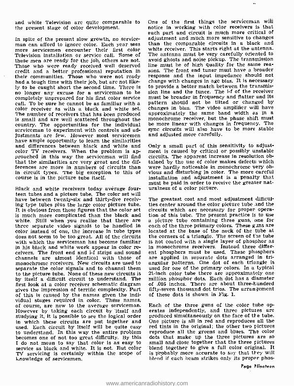
The greatest cost and most adjustment difficul- ties center around the color picture tube and the circuits which are necessary for proper opera- tion of this tube. The present practice is to use a picture tube containing three guns, one for each of the three primary colors. These guns are located at the base of the neck of the ;ube at the corners of a triangle. The screen of tie tube is not coated with a single layer of phosphor as in monochrome receivers. Instead three differ- ent phosphors must be used. These phosphors are applied in separate dots arranged in tri- angular patterns. One dot of each triangle is used for one of the primary colors. In a typical 21 -inch color tube there are approximately one million phosphor dots. Each dot has a diameter of .016 inches. There are about three- hundred fifty -seven thousand dot trios. The arrangement of these dots is shown in Fig. 1.
Each of the three guns of the color tube op- erates independently, and three pictures are produced simultaneously on the face of the tube. One picture is all in red and reproduces all the red tints in the original; the other two pictures reproduce all the greens and blues. The color dots that make up the three pictures are so small and close together that the three pictures blend together to give a full color original. It is Probably more accurate to say that they will blend if each beam strikes only its proper phos-
Page Nineteen
www.americanradiohistory.com

tions may be pressed into service for point -to- cutting in as desired.
In order to prevent a beam from striking the wrong phosphor while it is in motion across the screen, a perforated metal plate is placed be- tween the electron guns and the screen. This plate has one hole for each group of phosphor dots. This hole centers above the triangles shown on the dot pattern of Fig. 1. Since this plate cuts off a part of each beam it is called the shadow mask. The beams can strike the phos- phor only when they pass through the holes in the mask. The beams must all pass through the same hole at any given time. As the beams from the three guns pass through the hole they con- verge and cross over and then continue on to the screen.
Each of the three guns has all of the adjustments normally found on a single gun of a monochrome tube. The brightness of each color must be con- trolled individually and each beam must be in- dividually focused on the screen. After leaving their respective guns the three beams pass through a common electrode which causes them to converge at the mask. The beams must travel different distances to reach the different parts of the mask and screen as they scan across. So the convergence electrode must have not only a do potential but an ac component which is obtained from the vertical and hori- zontal sweeps. The addition of this ac sig- nal causes the distance from the guns at which the beams converge to change with the position of the beam. The focus of each individual beam is modulated in the same way in some receivers so that the focus of each beam is sharp at all dot groups regardless of their position on the screen.
The convergence of these beams is affected by small manufacturing variations and by stray magnetic fields in the vicinity of the gun. These effects are compensated for by placing small magnets at each gun. The exact position of these magnets is adjusted for proper convergence at the center of the screen. In order to obtain ac- curate convergence at the edges of the tube face it is necessary to neutralize any stray magnetic fields which exist at the front of the receiver. This is accomplished in some cases by a coil wound around the rim of the tube through which is passed a direct current. In other cases eight small magnets are positioned around the rim and adjusted for a flat magnetic field across the entire face of the tube. Another magnetic field common to all three beams is set -up at the neck of the tube before the beams have passed through the deflection yoke. This magnetic field may be obtained by passing a direct current through a solenoid or by use of permanent mag- nets. This is called a purifying coil or magnet. The strength of this field is varied to compen- Page Twenty
sate for misalignment of the gun structure dur- ing manufacture. This misalignment can cause the beams to strike the wrong color phosphor.
All of these convergence adjustments are ex- tremely critical. Some interaction will be noticed between the different adjustments. Even a change in the high voltage accelerating po- tential can upset a carefully made convergence adjustment. For this reason the high voltage ap- plied to the accelerating anode of these tubes is regulated by means of a vacuum tube regulator. The use of a regulator tube of this type allows careful and variable adjustment of the high voltage supply output.
The accuracy required in focusing and converg- ing the beams is so great, and the beams are so sensitive to external fields that even the earth's magnetic field can affect the adjustments. This is one of the great drawbacks of present color Television receivers. Some sets have as high as twenty -seven controls to adjust to obtain proper picture tube operation. After all these adjustments are made, if the set is moved from one part of the room to another some or all of these adjustments will have to be made over.
Fortunately the manufacturers are as aware of the problems of complexity and critical adjust- ment as anyone. They realize that while color has great appeal, the difference in cost between color and black and white is greater than most family budgets can stand. Each manufacturer is devoting considerable effort to simplifying the adjustment and reducing the cost of the receivers.
Improved manufacturing techniques have in- creased the size and resolution of the picture tubes without materially increasing the cost. In fact the cost of some of the smaller tubes has been reduced. Constant investigation is going on leading toward different internal tube construc- tions. One tube using strips of phosphor instead of dot groups and having its guns in a horizontal line instead of a triangle has already been an- nounced. This tube will greatly simplify the convergence problem. Where present color tubes require convergence adjustments in both the horizontal and vertical planes, this new tube will require adjustment only in the horizontal direc- tion since the beam will always strike the proper color even when slightly higher or lower. Un- fortunately this tube will not be available on the market for several years.
In contrast to the cooperation between manu- facturers in developing a color Television system so that all sets would be built to the same speci- fications, each color tube manufacturer set about solving the problems of beam convergence and color control in his own way. This of course is only natural in a highly competitive market. Each manufacturer logically enough seeks to de-
www.americanradiohistory.com

FIG. I. Arrangement of color phosphor dots on the screen of a three -gun color tube.
velop the best possible tube for the use so that he himself can market it. After all business is business. As a result of the different approaches used by different manufacturers; the tubes man- ufactured by different plants are not inter- changeable. The set must be designed around the tube; the tube is not designed for the set. This means that as newer and better color tubes become available it will not be possible to use them as replacements in older sets without mak- ing extensive changes in the circuitry of those sets. Since any tubes developed in the future to be called "better" will have to be cheaper, the owners of sets with old type tubes will always be faced with more expensive replacements. This is a condition which did not exist in the develop- ment of black and white receivers. In this case set owners were able to take full advantage of any savings in the price of replacement tubes which came about due to improved tube types and improved manufacturing techniques and the reduced sales cost resulting from high production.
In addition to the improvements in picture tubes and reduced costs, the color demodulator and control circuits have also been greatly simplified within the past year. Whereas the first color sets used up to thirty -five tubes in addition to the picture tube, present receivers now have been reduced to as low as twenty -six tubes. In part this came about through the development of dual -purpose tubes, but for the most part it is due to improvements in circuitry. In some cases
the number of components and connections has been reduced as much as 30 %. This represents a very real saving in manufacturing costs. These circuitry improvements have not only resulted In cost savings but in improved performance of the receiver as well.
As you can readily see color TV has now passed the stage of : "Get the picture and hang the cost." It is now in the stage of: "Improve the picture and cut the cost." In this same stage the cost of black and white receivers was reduced from 50% to 75 %. It would not be correct to say that all the savings went hand in hand with im- proved picture quality or resulted in sets which were easier to service. However, few of these savings degraded the picture quality greatly and a reduced complexity definitely made receivers much easier to service. We can expect color re- ceivers to go through this same phase. There will be many changes in circuitry and greatly reduced costs of production. Some of the changes in circuitry that will be tried will seri- ously degrade picture quality, others will make servicing more difficult, but on the whole the picture will get better, the cost lower, and serv- icing easier.
As the cost of the sets goes down and their sta- bility improves more and more people will buy them for home use. As these sets come into more common use, the serviceman will note the effect quite readily on his cash register. The
(Page 23, please) Page Twenty -one
www.americanradiohistory.com

Tecitifical 2 By B. VAN SUTPHIN
NRI Consultant
Subject: Ion Trap Magnets and Ion Burns
r ONSIDERABLE confusion exists regarding ion trap magnets and ion burns. This is un-
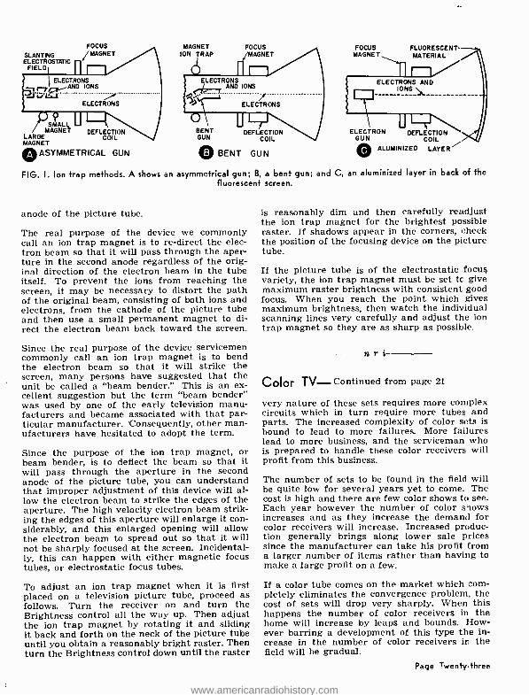
derstandable since the term "ion trap magnet" was poorly chosen and does not indicate the ac- tual purpose of the magnet. From the name, it would seem that the magnet somehow traps out the ions and prevents their reaching the surface of the screen. This is not true. The relatively weak magnetic field cannot appreciably affect the heavy ions and change their course. The "ion trap magnet" actually bends the electron beam back toward the screen after the ions have been aimed in a direction such that they cannot pos- sibly reach the screen and cause damage.
In the early days of television, tubes with electro- static deflection were used. The 7JP4 tube is typical of this type. Both the electrons and the ions were deflected equally by the changing electrostatic field, and the ions did not strike the screen at only one point to produce a burn.
With the advent of larger tubes, however, elec- tromagnetic deflection became the only practical means of obtaining the greater deflection neces- sary and special electromagnetic tubes had to be designed. These tubes used a changing electro- magnetic field for deflection purposes. The changing magnetic field, however, did not affect the passage of the ions through the tube. All of the tubes in use at that time were of the straight -gun variety, and both the electrons and the ions left the electron gun together. The ions, unaffected by the electromagnetic field of the sweep coils, traveled straight down the center of the tube to strike the screen.
Bombardment by these heavy ions ultimately burned the phosphor coating on the screen and prevented that portion of the screen from light- ing normally. The end result was a brown spot in the center of the tube.
Two different means of solving this problem were tried. The first involved placing a thin coat - Page Twenty-two
ing of aluminum behind the phosphor and there- fore between it and the electron gun. This thin coating of aluminum would let the electrons go straight through, but would prevent the heavier ions from passing and striking the screen.
The 10FP4 tube, typical of the early aluminized tubes, did not require an ion trap since it was of the straight -gun variety and the electrons were aimed directly at the screen from the first. This type of electron gun is illustrated in Fig. 1-C.
Modern tubes of the aluminized variety require ion trap magnets since they do not use simple straight electron guns. Some use a bent gun ar- rangement, but most use a straight electron gun that is pointed off to one side so that the ions will not travel toward the screen. The ion trap magnet is necessary to redirect the electron beam toward the screen.
At about the same time, a picture tube employ- ing the "slash -gun" was designed. This type of picture tube required the use of a double - magnet ion trap. The two magnetic fields were required to deflect the electron beam off its orig- inal course, and then deflect it back to its orig- inal course so that the electrons could strike the screen. The electrostatic field created by the "slash" in the electron gun would affect the movement of both the electrons and the ions. Therefore, it was necessary to deflect the elec- tron beam back to a course such that it would pass through the aperture in the second anode of the picture tube.
A third technique for preventing the ions from reaching the screen came later. This was the "bent -gun" type tube shown in Fig. 1 -B. Notice that the electron gun is bent so that both the electrons and the ions are directed away from the screen. A single- magnet ion trap is then used to re- direct the electron beam so that it will pass through the aperture in the second
www.americanradiohistory.com
FOCUS MAGNET
SLANTING /MAGNET ION TRAP ELECTROSTATIC
FIELD
FOCUS MAGNET
FOCUS MAGNET
FLUORESCENT- MATERIAL
ELECTRONS AND IONS
....
ELECTRONS
ELECTRONS AND IONS
SMALL MAGNET
LARGE MAGNET
O ASYMMETRICAL GUN
DEFLECTION COIL
BENT GUN
O BENT GUN
DEFLECTION COIL
ELECTRON DEFLECTION GUN COIL
coALUMINIZED LAYER
FIG. I. Ion trap methods. A shows an asymmetrical gun; B, a bent gun; and C, an aluminized layer in back of the fluorescent screen.
anode of the picture tube.
The real purpose of the device we commonly call an ion trap magnet is to re- direct the elec- tron beam so that it will pass through the aper- ture in the second anode regardless of the orig- inal direction of the electron beam in the tube itself. To prevent the ions from reaching the screen, it may be necessary to distort the path of the original beam, consisting of both ions and electrons, from the cathode of the picture tube and then use a small permanent magnet to di- rect the electron beam back toward the screen.
Since the real purpose of the device servicemen commonly call an ion trap magnet is to bend the electron beam so that it will strike the screen, many persons have suggested that the unit be called a "beam bender." This is an ex- cellent suggestion but the term "beam bender" was used by one of the early television manu- facturers and became associated with that par- ticular manufacturer. Consequently, other man- ufacturers have hesitated to adopt the term.
Since the purpose of the ion trap magnet, or beam bender, is to deflect the beam so that it will pass through the aperture in the second anode of the picture tube, you can understand that improper adjustment of this device will al- low the electron beam to strike the edges of the aperture. The high velocity electron beam strik- ing the edges of this aperture will enlarge it con- siderably, and this enlarged opening will allow the electron beam to spread out so that it will not be sharply focused at the screen. Incidental- ly, this can happen with either magnetic focus tubes, or electrostatic focus tubes.
To adjust an ion trap magnet when it is first placed on a television picture tube, proceed as follows. Turn the receiver on and turn the Brightness control all the way up. Then adjust the ion trap magnet by rotating it and sliding it back and forth on the neck of the picture tube until you obtain a reasonably bright raster. Then turn the Brightness control down until the raster
is reasonably dim and then carefully readjust the ion trap magnet for the brightest possible raster. If shadows appear in the corners, check the position of the focusing device on the picture tube.
If the picture tube is of the electrostatic focus variety, the ion trap magnet must be set to give maximum raster brightness with consistent good focus. When you reach the point which gives maximum brightness, then watch the individual scanning lines very carefully and adjust the ion trap magnet so they are as sharp as possible.
; ri
Color TV- Continued from page 21
very nature of these sets requires more complex circuits which in turn require more tubes and parts. The increased complexity of color sets is bound to lead to more failures. More failures lead to more business, and the serviceman who is prepared to handle these color receivers will profit from this business.
The number of sets to be found in the field will be quite low for several years yet to come. The cost is high and there are few color shows to see. Each year however the number of color shows increases and as they increase the demand for color receivers will increase. Increased produc- tion generally brings along lower sale prices since the manufacturer can take his profit from a larger number of items rather than having to make a large profit on a few.
If a color tube comes on the market which com- pletely eliminates the convergence problem, the cost of sets will drop very sharply. When this happens the number of color receivers in the home will increase by leaps and bounds. How- ever barring a development of this type the in- crease in the number of color receivers in the field will be gradual.
Page Twenty -three
www.americanradiohistory.com
Louis E. Grossman President F. Earl Oliver Vice Pres. Howard B. Smith Vice Pres. William Fox Vice Pres. Herbert Garvin Vice Pres. Louis L. Menne Executive Secretary
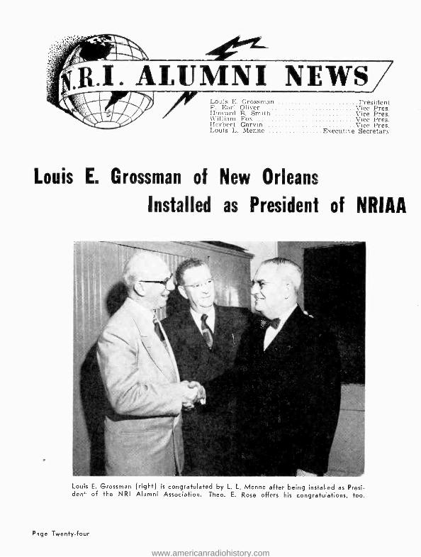
Louis E. Grossman of New Orleans
Installed as President of NRIAA
Louis E. Grossman (right) is congratulated by L. L. Menne after being installed as Presi- dent of the NRI Alumni Association. Theo. E. Rose offers his congratulations, too.
Page Twenty -four
www.americanradiohistory.com

Chapter Chatter Minneapolis -St. Paul Chapter officers and mem- bers have already made all arrangements for celebrating their second anniversary on Thurs- day, May 10. A banquet dinner will be held at 6:30 P.M. at Esslinger's Cafe, 1927 University Avenue. (near Prior), St. Paul. The menu will be Tomato Juice Cocktail, Tossed Salad, Relish, Club Sirloin Steak, Baked Potato, Apple or Cherry Pie, Rolls and Coffee. Lou Menne, Ted Rose and J. B. Straughn, all of NRI in Wash- ington, will be our guests. Following our dinner we will go to our regular meeting rooms in the St. Paul Midway YMCA for our business meeting at 8:00 P.M. Our guest speakers will then take over. Please mark your calendar. Set aside this date and be sure to attend.
Mr. Michael Kushill, Service Manager, Roycraft Co., Philco Distributors gave us a very interest- ing talk on the Philco line including Philco color. The Roycraft Company donated a Philco CRT Checker for a door prize which was won by our member, Robert Jansen, St. Paul.
For our February meeting Lew Bonn Co. donat- ed two Westinghouse picture tube carriers made of canvas. These were won by Charles Goodell and M. C. Lundgren.
Election of officers will take place in April. They will be installed by Mr. Menne in May. At this writing leading candidates for officers are Bob Cheeseman, Charles Goodell, Paul Donatell, Harold Holtz and Robert Jansen. These men have proved their fitness for office by being will- ing to take leadership whenever anything need- ed to be done. There are other good men, too, whose names may be advanced the night the election is held. This is a good time for our members to give thought to the men they wish to assume leadership for the next year.
John I. Babcock, who took the lead in organizing the Twin City Chapter and who has done such a fine job as secretary will retire from office temporarily but certainly will not relinquish his interest in the chapter. John is the inspirational type of leader who is bound to pop up in some important capacity.
Meetings are held on the second Thursday of each month at the St. Paul Midway YMCA. All NRI students and graduates in the Twin City area are cordially invited to attend meetings. Contact John I. Babcock, 3157 32nd Avenue S. Minneapolis 6, Minnesota.
Philadelphia- Camden Chapter members were privileged to hear Mr. Nunemacher of the Ad- miral Corporation. A fine talk on the Admiral line. Very much appreciated by the members.
We are arranging for a tour through the Bell Telephone Company to see how TV programs are piped out on microwave. The tentative date for this tour is April 23.
Our attendance has been unusually good. We are pleased to announce the following new mem- bers, Walter R. Hansell of Neshaminy, Penna.
Phila- Camden Chapter party. Around the table are Stephen Gilbert, Chairman John Pirrung Lou Menne, John McCaffery, Past President Chris Stokes
and Ted Rose.
Paul K. Becker, North Hills, Penna., Pasqual Patrizi, Philadelphia, Louis A. Hampton Pember- ton, N. J., Robert C. Renner, Woodbury, N. J. and Joseph Bokeny, Philadelphia.
Mr. Morris E. Heath, Service Supervisor, West- inghouse Corporation, who by the way is an honorary member of our chapter, presented a Visualcast of the Westinghouse printed circuit. This is one of the best lectures we have had on printed circuits. Mr. Heath covered the subject very thoroughly. He showed plates of the circuit
Mr. Harvey Morris, of Phila- Camden Chapter, giving a talk on horizontal troubleshooting.
Page Twenty -five
www.americanradiohistory.com
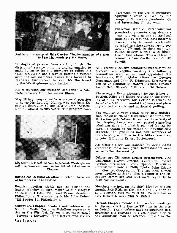
And here h a group of Phila- Camden Chapter members to hear Mr. Morris and Mr. Heath.
in stages of process from start to finish. He distributed service bulletins and schematics to make it easier for the members to follow his talk. Mr. Heath has a way of putting a subject over and our members always look forward to his talks. Our sincere thanks to Mr. Heath and to the Westinghouse organization.
All of us wish our member Ben Smith a com- plete recovery from his recent illness.
May 28 has been set aside as a special occasion to honor Mr. Louis L. Menne, who has been Ex- ecutive Secretary of the NRI Alumni Associa- tion for almost twenty years. The program corn-
Mr. Morris E. Heath, Service Supervisor, Westinghouse, with the Visualcast used in his talk at Phila- Camden
Chapter.
mittee has in mind an affair at which the wives of members will be invited.
Regular meeting nights are the second and fourth Monday of each month at the Knights of Columbus Hall, Tulip and Tyson Streets in Philadelphia. The secretary is Mr. Jules Cohen, 7124 Souder St., Philadelphia.
Milwaukee Chapter members were addressed by Mr. E. J. Wells, Customer Relations representa- tive of the Wis. Tel. Co. on microwaves called "Telephone Skyways." The lecture was vividly Page Twenty -six
who came
illustrated by the use of miniature equipment actually used by the company. This was a 45- minute talk and interesting all the way.
Chairman Ernie V. Bettencourt has promised the members, on alternate months, a visit to one of the local radio and TV stations. Also informal discussions by the members who will be asked to take some separate sec- tion of TV and, in their own lan- guage, deliver a talk with black- board illustrations. This will lead to comments from the floor and all will benefit.
At a recent executive committee meeting which preceded our regular meeting the following committees were chosen and appointed. Re- freshments, Philip Rinke, Literature, Guenter Opperman and John P. Edgerton, Secretary of Executive Committee, Robert Krauss, Finance Committee, Clarence P. Klier and Gil Nelson.
There was a lively discussion by Mr. Edgerton, Petrich, Klier and Rinke relating to the servic- ing of a TV receiver. Mr. Petrich is scheduled to make a talk on horizontal frequency and phas- ing control circuits and horizontal pulling.
The chapter is very proud of its new publica- tion known as NRIAA Milwaukee Chapter News. It is a fine publication. It reviews the activity of the chapter, keeps members posted regarding what was done and what is planned for the fu- ture. It should be the means of inducing NRI students and graduates not now members of the chapter, who live in the Milwaukee area, to join. Editor is Ernest Bettencourt.
An electric clock was donated by Acme Radio Supply Co. for a door prize. Refreshments were served after the meeting.
Officers are Chairman, Ernest Bettencourt, Vice Chairman, Slavko Petrich, Secretary, Robert Krauss, Treasurer, Louis Sponer, Executive Committee members, Philip Rinke, John Edger- ton, Guenter Oppermann. The last three named men together with the officers comprise the ex- ecutive committee and will meet regularly to plan coming events.
Meetings are held on the third Monday of each month, 8:00 P.M., at the Radio and TV shop of S. J. Petrich, 5901 W. Vliet St. Contact Secre- tary Robert Krauss, 2467 N. 29th St.
Detroit Chapter members held several meetings to discuss a bill to license TV men in the city of Detroit. The members have no objection to a licensing bill provided it gives opportunity to any ambitious man to advance himself in the
www.americanradiohistory.com

Detroit Chapter officers, front row, Finance Committee, Asa Belton, Treasurer, F. E. Oliver, Recording Secre- tary, James Kelly, Vice Chairman, John Nagy. Second row, Corresponding Secretary, Leo H. Blevins, Librarian, Prince Bray, Chairman, Edward V. Green, Sgt -at -Arms, Charles Mills, Finance Committee, Samuel Jackson.
industry. A representative number of members agreed to attend the hearings and to express their views to the Councilmen.
The following men were elected to serve the chapter during the next year.
Chairman, Edward V. Green, Vice Chairman, John Nagy, Secretary, James Kelly, Correspond- ing Secretary, Leo H. Blevins, Treasurer, F. E. Oliver, Sgt. -at -Arms, Charles Mills, Librarian, Prince Bray, and Finance Committee, Asa Bel- ton and Samuel Jackson.
At one meeting there was a demonstration of Hickok test equipment under the direction of Mr. George Kangan. Another meeting was de- voted to a discussion of the fundamentals of color TV.
Edward V. Green, peppy chairman of Detroit chapter.
Mr. John McCaul, Sales Service Engineer, Sylvania, addressing Springfield Chapter.
Meetings are held on the second and fourth Fri- day of each month at 8:00 P.M. at 431 E. Con- gress St., Detroit. If you would like to receive notices regarding meetings of Detroit chapter please send your name and address to James J. Kelly, secretary, 1140 Livernois, Detroit 9,
Michigan.
Springfield, Mass. Chapter members were enter- tained by Mr. Gabriel Bedard who gave an in- teresting talk on Fire Alarm Systems and How They Operate. Later chapter members visited fire alarm system headquarters to view the op- erations. We were shown how firemen were sent to locations as quickly as possible through code, teletype, etc. We were shown a non- inter- fering device which is used to prevent one alarm from interfering with another even if both are sent at the same instant from different fire boxes. Many other operations were care- fully explained and demonstrated. It was an in- teresting evening.
At another meeting we had a very interesting film on electronic organs. Chairman Ray Nys- trom, a specialist in this field, was the narrator.
A visit to Western Union Headquarters is planned for the near future.
The high -light event, since our last report, was an informal and practical meeting given by Sylvania and sponsored jointly by our Spring- field chapter and Young and Young of Spring- field. The meeting was designed to show how to make work easier, faster, and more interesting.
Page Twenty -seven
www.americanradiohistory.com

Henry Merheb of Springfield Chapter is drawing lots from a ballot box to pick winners of the twelve door prizes which were awarded at a meeting sponsored jointly by Springfield Chapter and Young and Young
of Springfield.
It was a fine opportunity to obtain valuable in- formation on electronics as they apply to the service technician. There was a question and answer period. The meeting was held at the Building of Electrical Progress. Seating capac-
Officers of Springfield, Mass. Chapter are, front row, left to right, Chairman, Ray Nystrom, Vice chairman, Howard B. Smith, Secretary, Marcellus Reed, and Treas- urer, Arnold Wilder. Second row, Executive Com- mittee, Lyman Brown, Leo Martin, and Stanley Malec.
Page Twenty- eig'1t
ity is 250. All seats were occupied. Present from Sylvania were Sam McDonald, Sales Man- ager, Dave Tolins, Editor, Sylvania News and Advertising Supervisor, Jim Sutherland, New England Sales Manager and John McCaul, Sales Service Engineer. Mr. McCaul was speaker of the evening and did a wonderful job. He spoke for 21fz hours with scarcely a pause. In spite of the length of his talk there was no sign of unrest in the audience. Our very great thanks to Mr. McCaul and his associates for this profitable evening.
Of the 250 present more than 40 were members of our Springfield chapter. Twelve door prizes were awarded and four went to our members, namely E. A. LaClair, Flynn, E. J. Perry and T. Glog.
The chairman of Springfield chapter is Ray- mond Nystrom, 36 Baltimore Avenue, Spring- field, Mass. The secretary is Marcellus Reed, 41 Westland St., Hartford, Conn.
New York Chapter, moving along in grand style, has been very active. Phil Spampinato read a poem entitled "The Faithful Few." Phil also spoke on HI -FI Audio Servicing. Frank Catalano spoke on TV Experiences, Tom Hull spoke on TV Front -Ends, Dave Lion spoke on Voltage Supplies.
Frank Zimmer was a speaker at one meeting and delivered a bang -up talk on HI -FI tape record- ing. Zimmer spoke on the history of magnetism, on the history of tape recording, its essential functions in today's broadcasting and television industry. After the lecture, Zimmer demonstrat- ed HI -FI Tape Recording using his own twin - trax tape recorder. This talk was one of the outstanding events of the year.
The members are so pleased with the work of our officers the entire slate was re- nominated and elected to serve during the next twelve months. All officers are doing their share with genuine credit to themselves and to the chapter. An especial word of appreciation should go to secretary Ernest E. Paul whose meticulous min- utes and reports to headquarters cover every single activity.
Meetings of New York chapter are held on the first and third Thursday of each month at St. Mark's Community Center, 12 St. Mark's Pl., be- tween Second and Third Avenues, New York.
Flint, Michigan Chapter, better known as the Saginaw Valley Chapter, has decided to experi- ment by holding meetings at the shops of mem- bers wherever space is available. Because many members have test equipment of various kinds, it is believed the members will benefit material- ly by coming in contact with the equipment. The
www.americanradiohistory.com

chapter will, nevertheless, use their regular quarters in the Buick Local Union Hall when representatives of the Television and Electronic Industry are engaged to give lectures and dem- onstrations.
We attended a meeting of the Bell Telephone Co. of Michigan. Two engineers presented a very interesting program on the application of transistors in the telephone system.
The following officers were elected for the cur- rent year. Chairman, Warren A. Williamson, 1201 Allen St., Flint 7, Michigan. Vice Chair- man, George Mitru, 1061 E. Alma St., Flint 5, Michigan, Secretary, George Rashead, 338 E. Marengo Ave., Flint 5, Michigan. Treasurer, David J. Nagel, 3135 E. Mt. Morris Rd., Mt. Mor- ris, Michigan.
Students and graduates in the Saginaw Valley area are cordially invited to attend meetings. Contact Secretary George Rashead, address above, who will be glad to send notices regard- ing meetings.
New Orleans Chapter members continue to meet on the first and third Tuesday of each month at 8:00 P.M., in the recreation room of Louis E. Grossman, 2229 Napoleon Ave.
The event of the year was held in the old French Quarter at 528 Bienville St. at which time L. L. Menne installed Mr. Louis E. Grossman as Na- tional President of the NRI Alumni Association. Mr. Ted Rose, from headquarters, was also our guest. The committee on arrangements, lead by Mr. Anthony H. Buckley, secretary, provided shrimp and other delicacies to make this an af- fair long to be remembered. Believe us, this man Buckley is quite a cook. There was liquid re- freshments, and plenty of the usual good and corny speeches.
Alfred G. Francis, our Chairman, has opened a full time service shop called Guaranty TV and Radio Service, 1808 Magazine Street, New Or- leans, Louisiana.
Dowie Gendron, formerly employed in a sugar refinery at Reserve, La., has opened a shop in LaPlace, La. Both men report that they have more business than they can handle.
Meetings are well attended. The new officers are very active and have plans for splendid meetings. We shall be pleased to have visits from any students or graduates in this area. For information regarding meetings, address Chairman Alfred Francis, 1928 Louisa St., New Orleans 17, La., or Secretary Anthony H. Buck- ley, 305 Serpas Dr., Arabi, La.
Baltimore Chapter, as this issue goes to press,
has scheduled a big blow -out to honor L. L. Menue. The date is April 10. Not only are Balti- more members going to turn out in full force but delegations are expected from Pittsburgh, Phila. delphia and Hagerstown. Refreshments will be served.
Meetings are held regularly on the second Tues. day of each month at 100 N. Paca Street, Balti. more.
Chicago Chapter, surging forward under the combined leadership of chairman Walter H. Nicely and secretary Charles C. Mead is receiv- ing the plaudits of its members for fine programs on color TV fundamentals. Radio, too, is none- theless in command of attention for there are many more of them in use since the dawn of TV.
All efforts are made to coach those who mani- fest a desire for help and guidance in service work on all radio and television. The open service forum is always interesting. Members are urged to bring in their problem chassis and the leaders go to work on them. Questions at any time are invited. Advice and show -how is gladly given whether trivial or complicated. Members are as- sured a profitable and beneficial experience.
We are looking forward to a visit by L. L. Menne and Ted Rose of Headquarters. Meetings are held on the second and fourth Wednesday of each month, 33rd Floor, Tower Space, American
I FIGHT CANCER
itlr (( (liecki(p
11)1(1 (1 check
AMERICAN CANCER SOCIETY
Pacio 1worr,.
www.americanradiohistory.com
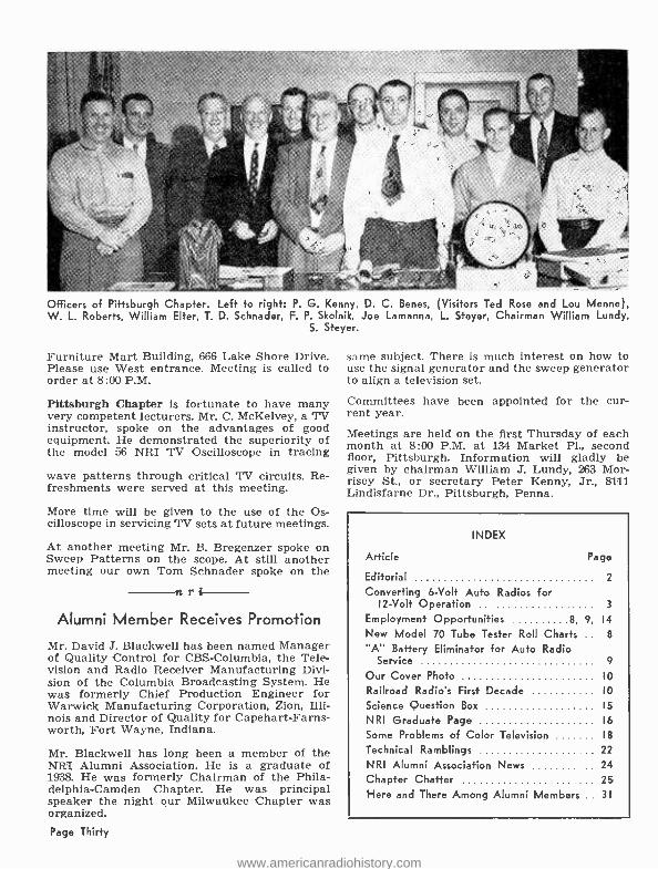
Officers of Pittsburgh Chapter. Left to right: P. G. Kenny, D. C. Benes, (Visitors Ted Rose and Lou Menne), W. L. Roberts, William Elter, T. D. Schnader, F. P. Skolnik, Joe Lamanna, L. Stayer, Chairman William Lundy,
S. Steyer.
Furniture Mart Building, 666 Lake Shore Drive. Please use West entrance. Meeting is called to order at 8:00 P.M.
Pittsburgh Chapter is fortunate to have many very competent lecturers. Mr. C. McKelvey, a TV instructor, spoke on the advantages of good equipment. He demonstrated the superiority of the model 56 NRI TV Oscilloscope in tracing
wave patterns through critical TV circuits. Re- freshments were served at this meeting.
More time will be given to the use of the Os cilloscope in servicing' TV sets at future meetings.
At another meeting Mr. B. Bregenzer spoke on Sweep Patterns on the scope. At still another meeting our own Tom Schnader spoke on the
ri Alumni Member Receives Promotion
Mr. David J. Blackwell has been named Manager of Quality Control for CBS- Columbia, the Tele- vision and Radio Receiver Manufacturing Divi- sion of the Columbia Broadcasting System. He was formerly Chief Production Engineer for Warwick Manufacturing Corporation, Zion, Illi- nois and Director of Quality for Capehart- Farns- worth, Fort Wayne, Indiana.
Mr. Blackwell has long been a member of the NRI Alumni Association. He is a graduate of 1938. He was formerly Chairman of the Phila- delphia- Camden Chapter. He was principal speaker the night our Milwaukee Chapter was organized. Page Thirty
same subject. There is much interest on how to use the signal generator and the sweep generator to align a television set.
Committees have been appointed for the cur- rent year.
Meetings are held on the first Thursday of each month at 8:00 P.M. at 134 Market Pl., second floor, Pittsburgh. Information will gladly be given by chairman William J. Lundy, 263 Mor- risey St., or secretary Peter Kenny, Jr., 8111 Lindisfarne Dr., Pittsburgh, Penna.
INDEX
Article Page
Editorial 2
Converting 6 -Volt Auto Radios for 12 -Volt Operation 3
Employment Opportunities 8, 9, 14
New Model 70 Tube Tester Roll Charts .. 8
"A" Battery Eliminator for Auto Radio Service 9
Our Cover Photo IO
Railroad Radio's First Decade IO
Science Question Box 15
NRI Graduate Page 16
Some Problems of Color Television 18
Technical Ramblings 22
NRI Alumni Association News 24 Chapter Chatter 25
Here and There Among Alumni Members .. 31
www.americanradiohistory.com

Here And There Among Alumni Members Tony Sais, of Socorro, N. Mex., is now a TV Serviceman with the Hicks Engineering and Electrical Corporation. nri Graduate John N. Davis, Jr., of Nashville, Tennes- see, writes that his full time Radio -TV business is growing each year. nri--
Floyd Fetterly, of Austin, Minnesota, is now op- erating his own full time radio and TV repair shop. Strictly service. He fixes any make or age set. nri NRI Graduates Lionel Verble and Harold Cun- ningham have formed a partnership. They now own and operate the Sikeston Radio d TV Serv- ice, of Sikeston, Missouri. nri-- Robert C. Beckett, of San Diego, California, is doing very well as the owner of Beckett's Radio and TV Service. Grossed $10,000 last year, his second year in business.
nr We're glad to hear from R. E. McKerral, who graduated from NEI in 1936. He now operates McKerrall Radio Service, in Laramie, Wyoming.
nri Congratulations to James L. House, Jr. of Vestal, New York. He is employed with IBM, and has been promoted to Coordinator between two of the company's plants on the Model 705 Electronic Data Processing Machine. nri-- Emerson A. Breda, of Tacoma, Washington, re- ports a successful year of spare -time servicing for 1955. Gross income was $3800, including 8 TV sales. No advertising to date. Just satisfied cus- tomers! ri- - Alvin W. Coleman, of Greggton, Texas, is em- ployed with Brown -TV Radio Service. Enjoys his work very much.
r.ri NRI Graduate Lyle D. Esch, of Lansing, Michi- gan, now has his own business, known as "Mod- ern TV Center." --ti r Donald Peters, of Newton Falls, Ohio, now holds his 1st class radiotelephone, 2nd class radio- telegraph, and advanced class amateur licenses.
His amateur call is W8HDF. Graduate Peters is a radio operator and technician for the Ohio State Highway Patrol.
nri Graduate Doug Bradshaw, of Hamilton; Ont., Canada, is in business for himself.
nri Ruben Phillips, of Cincinnati, Ohio, has been transferred to the Electronic Department of the Cincinnati Milling Machine Co. as a result of his NRI training. nri Lewis Grainger, of Glenallen, Virginia, has just opened his own full -time business, the West End Electronics. nri Lester W. Pearce, of Winnemucca, Nevada, is now Chief Engineer of Radio Station KWNA. nri-- Graduate G. T. Chambers, of Baltimore, .Mary- land, is employed as a technical publications writer with the Glenn L. Martin Co.
nri Adolf Striberny, Jr., a member of Philadelphia - Camden Chapter, visited NRI and Alumni Head- quarters recently.
nri Bruce Burroughs has an interesting name for his shop in West Cornwall, Connecticut. He calls it the Toll House. The building was the toll house for a covered bridge about 200 years ago. Mrs. Burroughs does the bookkeeping, also makes aprons and sells bric -a-brac in the front of the building. -nri Richard S. Sleightholm, of Buzzards Bay, Massa- chusetts, opened a part -time Radio -TV Shop in East Wareham in May of 1955. He reports a gross income of $8990 for 1955, part time!
nri Edward Ravitsky, of Northumberland, Pennsyl- vania, is only 17 years of age and already has a job as parts manager for a Motorola Distributor. Bright young man.
Rayfield J. Relihan is tion WT'RP. Is also spare time.
nri Chief Engineer, Radio Sta- doing TV servicing in his
Wayne J. Flickinger, a Senior Electronics Electronics Co. Also
nri of Ft. Wayne, Indiana, is Technician at Farnsworth has an amateur station.
Page Thirty -one
www.americanradiohistory.com