53
::::.:::: :,..:.. .., ii/: .: ,..,.. ;’ :I:,: :.,,., ;((c::{ :: : OWNER’S HAND B,;,OOs

::::.:::: :,..:.. ..,
ii/: .: ,..,..
;’
:I:,:
:.,,., ;((c::{ :: :
OWNER’S HAND B,;,OOs

Copyright © 2007 Tohatsu Corporation. All rights reserved. No part of this manual may be reproduced or transmitted in any form or by any means without the express written permission of Tohatsu Corporation.

FOREWORD
To get the maximum amount of pleasure and performance out of an outboard motor it IS important that you understand the functions of the mechanism and learn to operate the controls with ease and confidence. This operatmg manual will explain the construction of the TOHATSU outboard motor and how to carry out periodical inspection. As TOHATSU follows a policy of continuous product improvement, it reserves the right to make changes to specifications without prior notice. For further informatmn please contact TOHATSU dealers or TOHATSU distributors.
v TOHAT5Ll CORPORATION

CONTENTS Page

1. SPECIFICATIONS

2. MAIN PARTS
1) Model M40C
/
0

2) Model M40CEF
t
-4

3) Model M40CEP
M40CEP

3. INSTALLATION
3-I. Mounting the engine on boat
(1) Setting position ..,......_ above keel line Distance between engines (Fig. 1 I
approximately 580 mm V2.8”1
(2) Transom height Fisl. 1 Twm engine mounting
Fit the engines so that the anti-cavitation plate is 30 - 50 mm (1.2” - 2”) lower than bottom of the boat by (30 - 50 mm1 (Fig. 21.
(3) Tighten engines to boat by cramp screw handle and bolt of engine bracket. Tighten Ant,-cavitation plate
engines to boat to prevent loss. (Fig. 31
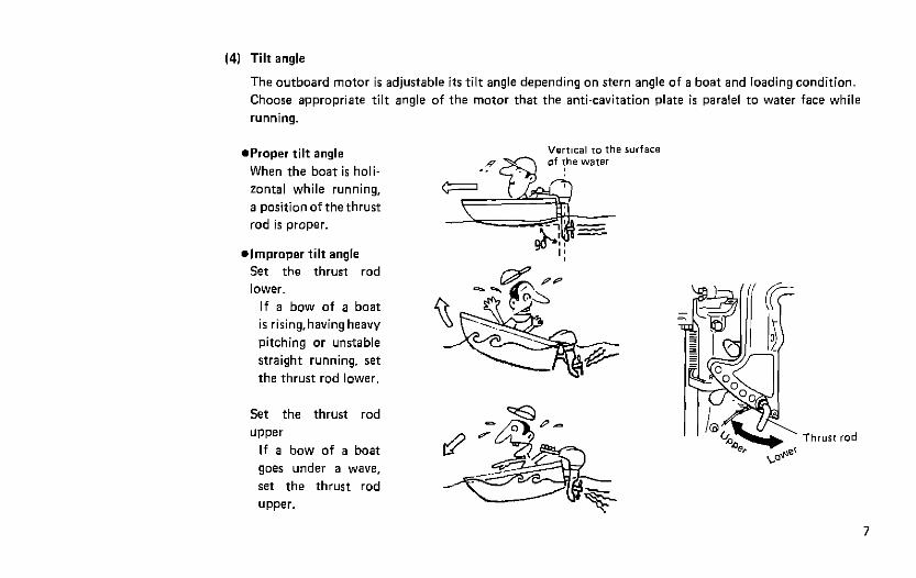
(4) Tilt angle
The outboard motor is adjustable its tilt angle depending on stern angle of a boat and loading condition.
Choose appropriate tilt angle of the motor that the anti-cavitation plate is paralel to water face while
running.
aProper tilt angle
When the boat is holi-
zontal while running,
a position of the thrust
rod is proper.
l improper tilt angle
Set the thrust rod
lower.
If a bow of a boat
is rising,having heavy
pitching or unstable
straight running, ret
the thrust rod lower.
Set the thrust rod
UPPer
If a bow of a boat
goes under a wave,
set the thrust rod
upper.

3-2. Installing the remote control device Erplanarion of rlght hand Remme Conrro, BOX is written

I Shift Remme Cable
Throttle Remore Control Cable

(31 Fitting of holder cap (1) Throttle side
l Take out the grommet from the advancer arm side of the lower motor cover.
l Set the grommet on the cable after making a I
hole in grommet. I
l Attach holder cap to cable and lock in PoSi- tion by nut. Throttle ride cable
(2) Shift side Holder cap
l Take out the grommet from the shift lever side of the lower motor cover. Shift ride cable
l Set grommet in position. l Attach holder cap to cable and lock in Posi-
tion by nut.
(4) Fitting of remote control cable to engine
Note: Position the control lever to Neutral with free accel lever is in the throtde’closed’ Position.
l Pass throttle cable through hole provided on the lower motor cover advancer arm side. l Install the holder cap of end tip of the throttle cable on the ball joint. l Fix the throttle cable by cable clip using groove of the cable. . Install the grommet on the motor cover lower.
10

(1) Fitting of Cord Assembly
l Pass the Cord Assembly from the Remote Control Box
through the Motor Cover Lower and connect terminals
referring drawing right. l Fix the Cord Assembly by a
clamp.
11

l Set the terminals of the Lead Wires in the ~~5s ~eadwirs
Cable Terminal Holder.
3. Fitting the Drag Link (attached to EP type)
Drag Link parts have been provided. Refer to the drawing right for fitting. The Spacer will be needed depending on kinds of steering cables.
12

3.5. Mounting the battery
(11 Locate the battery box in a convenient position
away from possible spray damage. Securely
fasten both the box and battery so they do not
shake loose.
] The battery capacity is 70AH at 12V. 1
Note: (1) Use battery leads having sufficient length.
(2) Make sure that the battery leads are not
trapped between motor and boat when
turning. etc.
(3) If leads are incorrectly connected, the starter
may fail to operate.
(4) Be sure to connect (+) and l-1 leads correctly.
If they are misxonnected. charging system
will be damaged.
(51 Keep battery fully charged at all times.
(21 Connect the positive lead (+I to the positive
terminal (+) of the battery. and then connect
the negative lead (6). When disconnecting the
battery always remove the negative lead (-1
first. After connecting peace a protective cover
on the positive terminal (+I to prevent short
circuits.
13

3-6. Preparing the engine for operation end precautions
Always carry a spare tank (can) since running of fuel at sea may result in a serious accident.
Use only TOHATSU genuine engine oil in the fuel mixture.
[II Fuel (1) Fuel is mixed in the ratio 50 parts gasoline
and 1 part of Tohatsu genuine engine oil.
A new outboard mufur should be broken-in by running for the first 10 hours on fuel
j engineoill. 1 having a 2O:l rmxmg ratm (gasohne and
(21 When ordinary two cycle engine oil is used, fuel should be mixed in the ratio of either 2O:l or 15:l for breaking-in period.
(3) The use of poor quality gasoline and engine oil will shorten the life of an engine and also cause poor starting and other troubles. Be sure to use only high quality gasoline and Tohatsu genuine engine oil.
(4) Check that a tank contains a sufficient
amount of fuel before starting for the day’s operation.
14

. FUEL AND LUBRICANT FOR TOHATSU OUTBOARD MOTORS
Fuel Gasolin Premium (super) gasoline is highly recommended for TOHATSU Outboard motors. Fuel gasoline should be a minimum pump posted octane rating of 87 (91 by research octane rating).
Gasoline containing alcohole, methanol Imethyl), or ethanol (ethyl), may cause:
0 Wear and damage on bearings, piston. piston rings and cylinder liners
0 Corrosion on metal parts 0 Dererioration of rubber parts and plastic
parts.
Note: Engine damage resulting from the use of fuel con- taining such alcohl(s) is not the responsibility of
TOHATSU, and will not be covered under the lim. ited warranty.
Engine Oil Use genuine TOHATSU Outboard Motor Oil. I f TOHATSU Outboard Motor Oil is not available, another Marine Engine Manufacturers’ Outboard Motor Oil with NMMA(BIA) certified TC-W or TC.
W!l rating must be used to maintain theTOHATSU Outboard Motor Warranty.
Caution Do not mix different brands of oil. The mixing of different brands of oil or different kinds of oil even in same brand may cause jelling lgell, resulting in blockage of filter screens. This may lead to serious engine damage, due to the lack of powerhead lubrication.
15

121 Break-in Running
1) Break-in running time 10 hours
16
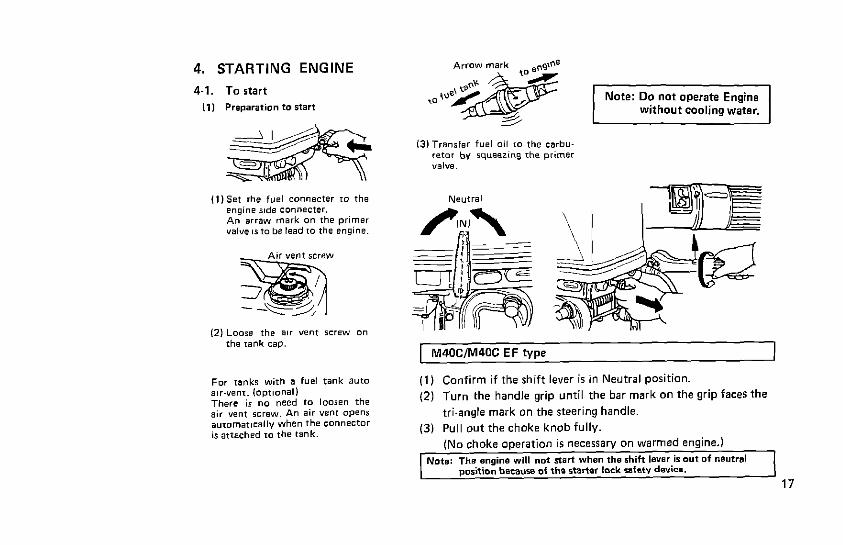
4. STARTING ENGINE
4-l. To start
111 Prsparation to start
M40ClM40C EF type
(1) Confirm if the shift lever is in Neutral position.
(2) Turn the handle grip until the bar mark on the grip faces the
tri-angle mark on the steering handle.
(3) Pull out the choke knob fully.

- l-7
EP type

(2) Starting
19

(3) If the recoil starter or starter motor fails to operate
(1 I Remove recoil starter COW and pull starter rope directly. (2) Use a 10 m/m socket wrench as a hand on the rope grip.
Note: Take care clothing is not caught in the rope when starting by this emergency
method.
20

4-2. Warming up engine
Warm the engine by running at low speed for about three minutes. This allows the lubricating oil to circulate
to all parts of the engine. Careful warming up will prolong the life of the engines
Note: If cooling water is not circulating over-
heating will occur. This will cause erratic
running followed by engine seizure.
l Engine speeds
Idling speed when warming up
Model Clutch in Clutch off
M40CIEFIEP 1 850rpm 1 950rpm
Maximum operating speed at full throttle.
Model Full throttle rpm range
M40WEFlEP 5,200 - 5.800
21

4-3. Forward and reverse running
( M40CIEF type 1
111 Forward
22

23

4-4. Stopping
M4OCIM40C EF type

A-5. Tilt up and tilt down
11) Tilt up
Move the reverse lock lever to the “RELEASE”
position. Tilt up the engine and lock by using tilt lever.
(2) Tilt down
Lift the engine up slightly and operate the tilt
lever upward to release lock system. Tilt down the engine.
(A reverse lock will work automatically -when tilting down an engine.1
25

4.6. Shallow water running
(1) Shallow water driving position
Put a reverse lock lever to “RELEASE” position. Set an engine on shallow water driving position by tilting up an engine and putting down a tilt
lever.
I21 Tilt down from shallow water driving position
Release an engine from shallow water driving position by bringing up it slightly and move a tilt lever to upward. By tilting down an engine, it will be reverse locked automatically.
Note: Reverse driving is to be done in trolling speed when an engine is at shallow water driving position. Do not increase engine revolution than requiring. To use an engine in high revolution is very dangerous, because of jumping up an engine from water.
Forward driving is to be done within engine revolution range that a propeller does not have cavitation.
26

4-7. Removing the engine from the boat
(1) Stop the engine. (2) Disconnect the fuel pipe connecter from the engine. 131 Remove the engine from boat. Empty water from the gear case.
When moving the engine aways keep the power head higher than the propeller. (4) When placing the engine on the ground again keep the power head on a higher level than the propeller
and keep the steering handle uppermost.
h = ,..............~,. . . . . . . . . . -:.:.:~:.:.I.,.>:~: . . . . . >2: .,... >> ,.,,,.....,., ,.....,.,.,.,.
27

5. ADJUSTMENTS
5-l. Adjusting steering reSist?Jnce 5-2. Adjusting a trim tab
If the boat fails to run straight, adjust the trim tab which YOU will find underneath anti-cavitation plate.
l (Example-l 1 If the boat has a tendency to pull to the right. move the trim tab in the direction A as shown in the drawing.
. (Example-2) Alternatively if it tend to pull to the left, move the trim tab towards B as shown in the drawing.
Note: A trim tab is also a sacrificial anode that protects against
corrosion. Do not paint it as this would made it ineffective function.
28

29

(1) Cleaning with fresh water
Wash down engine with fresh water to remove mud and salt from body casing. Flush out the cooling system with clean, fresh water after operating in salt or muddy water.
(1) Removing water plug from engine ’ Replace drain plug with flushing plug on engine and wash out engine with fresh water. (Close water strainer and sub water strainer on gear case with tape etc.. before washing out.)
Note: Take out a propeller from engine when use a flushing plug. Be sure to clean with frssh water before
storage for long term.
(2) Start engine in neutral position and flush cooling water system to remove salty or
muddy water.
Note: This work should be done with the
engine turning over slowly.
30

(2) Changing the propeller
Worn or bent propeller will
cause both poor engine perform-
ance and eventually engine
trouble.
l Take out the split pin and
remow propeller nut and
propeller thrust washer.
l Withdraw the propeller.
l Before re-assembling. apply
TOHATSU GREASE to the
propeller shaft.
-AL Gap 10.9 - 1.0 mm,
(31 Checking spark plug
Remove carbon from around the
center electrode. Replace with
new if necessary.
Note: Remove the igni-
tion wire to the
spark plug before
removing the pro-
peller in order to
prevent accidents.
31

(4) Trim tab (anode)
When the dimensions of the trim tab (anode), installed under the anti-cavitation plate, are reached replace it to a new immediately.
Note: l Neither apply oil nor paint to the trim tab (anodsL . Since the area around the mounting bolt for the trim tab tends to suffer from the electrical wrro-
sion be sure to tighten the bolt properly.
T Dimensional division (m/m) 1 pI , R;;ence dimensions
I .. I - I
Dimensions of new product
Dimensions for replacement
C -
51
43
-
0 -
50
44
-
32

(5) Changing gear oil
(1) Drain gear oil completely by
removing both upper and
lower plugs.
(2) Inject oil into lower oil I31 Replace upper plug, then
plug hole until it flows lower plug after withdraw-
from upper oil plug. ing oil injector.
Tighten lower oil plug.
33

(6) Cleaning fuel filter
Fuel filters are installed to both fuel tank and engine intake.
l When cleaning the filter on the tank side l When cleaning the fuel filter on the engine rmove 4 mounting sc.re~s and housing. side remwe the cap for the fuel filter.

35

6.3 Treatment before-after store motor
0 When a outboard motor is going to be re-used after long period store.
1) Run a engine with slow speed for 5 minutes.
2) Run a engine with half throttle for 10 minutes.
These are for cleaning of fitting engine oil inside of engine that was changed in quality. (I lowered performance by storing for long
period).
0 For daily using outboard motor.
Be sure to carry warming-up engine for at least 3 minutes to supply engine oil on required position.
0 Before storage engine
Drain engine oil in a cup of fuel oil filter assembly and clean filter element of it with kerosene or
part cleaning liquid before storage to avoid deterioration of oil itself in filter cup while storing for long period.
36

6-4. The “SUBMERGED” motor in water
If the outboard motor would be submerged into water it must be immediately disassembled and oiled. If this
is neglected or delayed, all parts of the engine may become rusty and corroded and may become unstable.
The emergency measures include:
11) Remove the engine from water and wash seawater and mud from the engine with fresh water.
I21 Remove the spark plug and remove water from the cylinder by turning the engine over by the starter rope.
(3) After discharging water inject TOHATSU genuine engine oil into the cylinder through the spark plug holes
and from the carburetor side and disperse the engine oil by turning the engine over again by recoil starter
‘OPE
141 After taking these emergency measures have your engine repaired at your TOHATSU dealer as soon as
possible.
6-5. Laying up the engine in winter
If the boat with an outboard motor mounted is moored for some time under conditions where the air tem-
perature falls below 0°C. water in the cooling water pump may freeze and damage the pump impeller. To
prevent water from freezing. the lower part of the motor is kept in the water or discharge water completely
from the pump by turning the engine by the starter rope when it is in the tilted up position.
37

7. TROUBLE SHOOTING
Possible causes of engine troubles are listed below.
For checking and repairing the engine. refer to this table. Contact your TOHATSU dealer as required.
ITarT. k . . .
.
f- . .
I . T= . . . . . . . . Distorted fuel q ioe
. . . . . Improper gasoline
. . . . . . Excessive oil in mixture I I I I I I . I
38

39

8. ATTACHMENTS
Name Quantity Dimensions Remarks
Tool bag 1 Pliers 1
TOOIS 10 x 13 socket wrench 1 lOwl3mm 21 socket wrench 1 21 mm Socket wrench handle 1 Slotted-head screwdriver 1
starter rope 1 1000 mm
Spare parts Spark plug 1 NGK 87HS-10 or
CHAMPION L82YC
Split pin 1 (Gap: 1.0 mm1
Fuel tank 1 Primer valve A com-
plete set Remote control box A com- (EP type only)
plete set Other items packed Remote control fitting A com- IEP type only1
parts plete set Drag link A com- (EP type only)
plete set Flushing plug 1

9. OPTIONAL ACCESSORIES
. .
%;,, b
VI Meter lamp witch
(111 TOHATSU grease 150 9.260 d
112lTOHATSlJ gear oil 1260 cc. 600 ccl

42
/l846 ‘.--------J .k,l

10. PROPELLER SELECTION
Light duty boat - Heavy duty boat (propeller dimensions: Cl x PI
Propeller Mark
14 13 12 11 10 9 a.5 7”
(mm) 260x352 262x322 266x296 268x267 275x252 276x226 285x220 290x160 Size
(inch) 10.2x13.9 10.3x12.7 10.6x11.7 10.6x11.3 10.8x 9.9 10.9x6.9 11.2x 6.7 11.4x7.1
Note: Propellers are 3.blades type except * marked one. * marked propeller has 4-blades.
43

11. WIRING DIAGRAM
1. M40C TYPE
44

2. M4OCEF TYPE
45


4. REMOTE CONTROL BOX (RC3C. RC5C)
r-
-5
-
G
!Iif
47

: i


7r TOHATSU CCIRPORATION
J”“. ‘93
Printed I” Japan (Z)