68
TOL-O-MATIC, INC. CALIPER DISC BRAKES Excellence In Motion ® 0701-4000B CLICK HERE TO GO TO TABLE OF CONTENTS

TOL-O-MATIC, INC.
CALIPERDISCBRAKESExcellence In Motion®
0701-4000B
CLICK HERE TO GO TO
TABLE OF CONTENTS

Tol-O-Matic morally and financially supports international organizations which helppreserve and protect the environment on a global basis. When you are done with thiscatalog, please pass it along to someone else or recycle it again. Working together, wecan make a difference!
This catalog is printed in the U.S.A. on recycled paper.(50% recycled fiber, 10% post-consumer waste content)
© Copyright 1996 Tol-O-Matic, Inc. All rights reserved. BC3 Series, BC2 Series, H-Block, U-Block, Channel-Block, Power-Block, Adam Clutch and RotoGripper aretrademarks of Tol-O-Matic, Inc. Band Cylinder and Axidyne are registered trademarks of Tol-O-Matic, Inc.
Information furnished in this catalog is believed to be accurate and reliable. However, Tol-O-Matic assumes noresponsibility for its use or for any errors that may appear in this document. Tol-O-Matic reserves the right to changethe design or operation of the equipment described herein and any associated motion products without notice.Information in this document is subject to change without notice.
15M 8/97 SPI
CONTENTSINTRODUCTION TO CALIPER DISC BRAKES............................1
FEATURES................................................................................................2 - 3
APPLICATIONS......................................................................................4 - 5
SELECTION GRAPHS.........................................................................6 - 7
PNEUMATIC / HYDRAULIC BRAKES......................................8 - 21P-10 / H-10 CALIPER DISC BRAKES..........................................................8-9P-20 / H-20 CALIPER DISC BRAKES.....................................................10-11P-220 / H-220 CALIPER DISC BRAKES.................................................12-13H-220I CALIPER DISC BRAKES.............................................................14-15H-440 CALIPER DISC BRAKES...............................................................16-17H-441 CALIPER DISC BRAKES...............................................................18-19H-960 CALIPER DISC BRAKES...............................................................20-21
HYDRAULIC MECHANICAL BRAKE COMBOS..............22 - 23H/ME-20 COMBINATION CALIPER DISC BRAKES........................22-23H/ME-220 COMBINATION CALIPER DISC BRAKES......................24-25
MECHANICAL BRAKES..............................................................26 - 33ME-10 CALIPER DISC BRAKES.............................................................26-27ME-20 CALIPER DISC BRAKES.............................................................28-29ME-220 CALIPER DISC BRAKES...........................................................30-31MB3 CALIPER DISC BRAKES.................................................................32-33
SPRING APPLIED BRAKES.........................................................34 - 43FS-20 CALIPER DISC BRAKES ...............................................................34-35FS-220 CALIPER DISC BRAKES.............................................................36-37FS-200I CALIPER DISC BRAKES ...........................................................38-39FS-440 CALIPER DISC BRAKES.............................................................40-41FS-595 CALIPER DISC BRAKES.............................................................42-43
DISCS, HUBS AND BUSHINGS...................................................44 - 50
TENSION CONTROL COMBINATIONS ........................................51
INTENSIFIER......................................................................................52 - 53
SELECTION.........................................................................................54 - 59
ORDERING..........................................................................................60 - 63
APPLICATION WORKSHEET............................................................64
Tol-O-Matic is proud toannounce its quality systemshave met the requirements topass ISO 9001 certification

CALIPER DISC BRAKES
1
Whether you need a hydraulic, pneu-matic, mechanical or spring appliedcaliper, one of our products will fityour application. Tol-O-Matic caliperdisc brakes put a stop to your prob-lems, providing maximum perfor-mance and product longevity.
Since 1962, Tol-O-Matic has beendeveloping pneumatic and hydraulicdisc brakes to compliment its powertransmission products. Over the years,the product line has grown to includehydraulic, pneumatic, mechanical andspring applied hydraulically releasedstyles with over 400 different types ofbrake models to fill countless applica-tion requirements.
Tol-O-Matic features a quality line ofpower transmission products that con-tinues to grow. Whether its a brakedesigned with a cooler operating spe-cial-vented disc or a caliper that com-bines both service and parking func-tions in one, we have a product foryou! It’s our job to uncover your brak-ing design problems and then developa cost-effective, efficient solution to
improve your products performance.
Need a custom brake for your appli-cation? Our engineers and state of theart design tools can create a special-ized design for your application in atimely manner. We can analyze thebest way to solve your applicationproblem and ensure customer inputall along the way.
Our engineering lab pushes our prod-ucts to the breaking point – runningthem 24 hours a day, 7 days a weekfor millions of cycles. If there is a wayto improve design we’ll find it. Wetest materials, manufacturing process-es and design to insure every productexecuted on paper performs in thefield as expected.
Parts are hand assembled and subjectto 100% inspection. Our experiencedprofessionals understand the productinside and out, checking quality inevery assembly procedure and againin final assembly. All brakes are thenpressure tested to maximum standardsbefore it leaves our factory. You can
be assured that, before it is shipped toyou, it meets the specified productperformance.
As our customer you set the deliveryschedule. Normal lead time in thebrake industry is measured in months.Standard Tol-O-Matic products deliv-eries are measured not in months orweeks but in days. Getting the productto you, when you need it, is just asimportant as product performance.We’re ready to make sure you getboth.
This catalog is designed to make iteasier for you to select and orderthe brake that will work for yourapplication. Graphs included showthe performance of each model.Selecting the correct brake can bea complicated process. Our staffwill do whatever it takes to be sureyou get the brake that best fits yourapplication. Call 1-800-328-2174to get friendly experienced help.
FEATURES
2
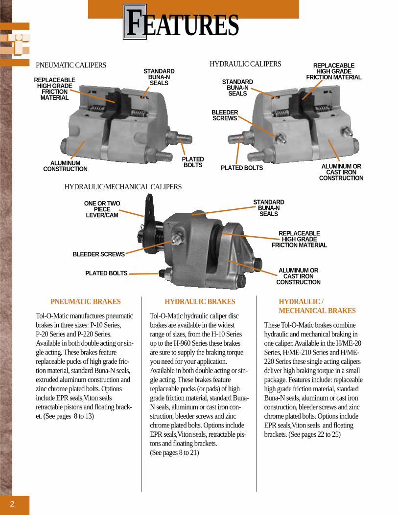
PNEUMATIC BRAKES
Tol-O-Matic manufactures pneumaticbrakes in three sizes: P-10 Series, P-20 Series and P-220 Series.Available in both double acting or sin-gle acting. These brakes featurereplaceable pucks of high grade fric-tion material, standard Buna-N seals,extruded aluminum construction andzinc chrome plated bolts. Optionsinclude EPR seals,Viton sealsretractable pistons and floating brack-et. (See pages 8 to 13)
HYDRAULIC BRAKES
Tol-O-Matic hydraulic caliper discbrakes are available in the widestrange of sizes, from the H-10 Seriesup to the H-960 Series these brakesare sure to supply the braking torqueyou need for your application.Available in both double acting or sin-gle acting. These brakes featurereplaceable pucks (or pads) of highgrade friction material, standard Buna-N seals, aluminum or cast iron con-struction, bleeder screws and zincchrome plated bolts. Options includeEPR seals,Viton seals, retractable pis-tons and floating brackets. (See pages 8 to 21)
HYDRAULIC /MECHANICAL BRAKES
These Tol-O-Matic brakes combinehydraulic and mechanical braking inone caliper. Available in the H/ME-20Series, H/ME-210 Series and H/ME-220 Series these single acting calipersdeliver high braking torque in a smallpackage. Features include: replaceablehigh grade friction material, standardBuna-N seals, aluminum or cast ironconstruction, bleeder screws and zincchrome plated bolts. Options includeEPR seals,Viton seals and floatingbrackets. (See pages 22 to 25)
PNEUMATIC CALIPERS
HYDRAULIC/MECHANICAL CALIPERS
HYDRAULIC CALIPERS
BLEEDERSCREWS
PLATED BOLTS ALUMINUM ORCAST IRON
CONSTRUCTION
REPLACEABLEHIGH GRADE
FRICTION MATERIAL
BLEEDER SCREWS
PLATED BOLTS
PLATEDBOLTS
ONE OR TWOPIECE
LEVER/CAM
ALUMINUM ORCAST IRON
CONSTRUCTION
ALUMINUMCONSTRUCTION
STANDARDBUNA-NSEALS STANDARD
BUNA-NSEALS
STANDARDBUNA-NSEALS
REPLACEABLEHIGH GRADE
FRICTION MATERIAL
REPLACEABLEHIGH GRADE
FRICTIONMATERIAL

3
MECHANICAL BRAKES
Tol-O-Matic manufactures a broadrange of mechanical brakes in theseseries: ME-10, ME-20, ME210,ME220 and MB3. Designed for use inareas that do not have access to othertypes of power, these single actingcalipers feature replaceable pucks(pads) of high grade friction material,cast aluminum or cast iron construc-tion and zinc chrome plated bolts. (See pages 26 to 33)
SPRING APPLIEDBRAKES
Tol-O-Matic offers spring appliedbrakes in sizes ranging from FS-20Series to FS-595 Series. These brakesrequire pressure (normally hydraulic)for disc release. Braking force is pro-vided by a stack (or stacks) ofBelleville spring washers. The concavewashers are capable of storing enor-mous force. When the brake is pressur-ized the force moves a piston(s) tocompress the spring washer stack(s),thus releasing the disc. These singleacting calipers feature replaceablepucks of high grade friction material,aluminum or cast iron construction,Buna-N seals and cadmium platedbolts. Options include EPR seals,retractable pistons and manual com-pensators. (See pages 34 to 43)
DISC AND HUBS
Tol-O-Matic offers several discs andhubs to fit your application. Most aremade of carbon 1010 steel, are flatwithin .010 inch, stress relieved andblanchard ground to an 80 (RMS)microinch finish. Discs also featuresocket head cap screw fasteners andkey way set screws. Standard discdiameters are 6, 6-5/16, 8,10, 12, and16 inches. Disc thicknesses rangefrom 5/32" to 1/2". Available: FixedHub and Disc Assemblies, Fixed Huband Disc Assemblies with Q.D.Bushings, Q.D. Bushings and Hubs,One-Piece Hub and Disc, Blank Disc,Disc with Bolt Circles and PilotHoles, and Ventilated Disc. (See pages44 to 51)
MECHANICAL CALIPERS
PLATED BOLTSALUMINUM ORCAST IRON
CONSTRUCTION
SPRING APPLIED CALIPERS
DISC & HUBS
PLATEDBOLTS
ONE OR TWOPIECE
LEVER/CAM
STANDARDBUNA-NSEALS
REPLACEABLEHIGH GRADE
FRICTION MATERIAL
REPLACEABLEHIGH GRADE
FRICTIONMATERIAL
ALUMINUM ORCAST IRON
CONSTRUCTION
SOCKET HEADCAP SCREWS
CARBON1010 STEEL
KEY WAY SET SCREWS
BELLEVILLE SPRINGWASHERS

Tol-O-Matic Caliper Disc Brakes find uses in industrial settings all over theworld. Used on everything from assembly lines to wind generators and lawn
maintenance equipment, Tol-O-Matic calipers offer the braking capacityyou need at an economical price. The variety of sizes, maximum torqueoutput and thermal capabilities insure you will find the optimal brake foryour application. These illustrations are meant to help you to see ways thatour calipers will work for you. At left a Spring Applied Brake is used on a
conveyor belt. In this application it will provide braking whenhydraulic pressure is Not provided to the brake. This type of
braking is especially useful in situations where safety is anissue. Since a Spring Applied Brake requires
hydraulic pressure to Release the brake, in apower shut down these brakes will engageproviding positive braking.
APPLICATIONS
4

Illustrated on the opposite page is another great place for Tol-O-Matic brakes, tensioning/constant slip applications. Used ineverything from mylar balloon fabrication to web presses, Tol-O-Matic pnuematic brakes provide dynamic tensioning that isadjusted by the air pressure supplied to the caliper. Because of the constant nature of this type of braking, caliper and disc aresized on thermal characteristics rather than torque.
5
Here two Tol-O-Matic pneumatic brakes are used toincrease the productivity of a CNC milling machine.In the original design users had to wait for themachine to coast to a stop before a part could beremoved or a tool changed. Electronic decelerationproved to be expensive and harmful to the motor. Tol-O-Matic caliper disc brakes improved stopping timeby 500 percent, increasing the machine’s productivityand safety.

SELECTION CHARTS
6
PERFORMANCE DATA
MECHANICAL BRAKES – COMPARATIVE MAXIMUM TORQUE VALUES
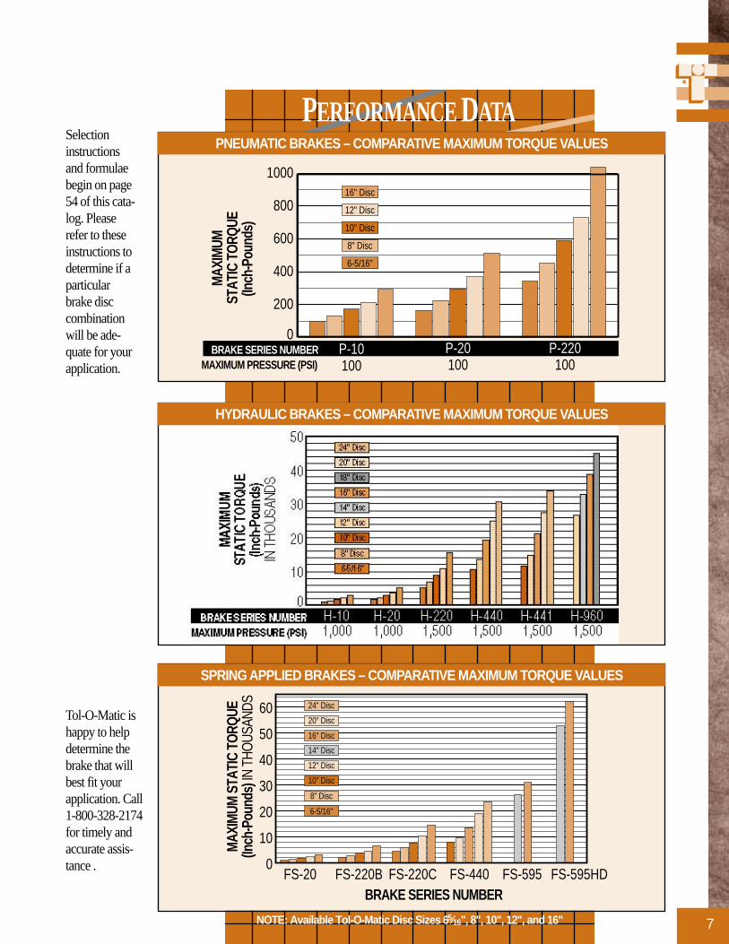
HYDRAULIC BRAKES – COMPARATIVE MAXIMUM TORQUE VALUES
MAX
IMUM
DY
NAM
IC T
ORQU
E (In
ch-P
ound
s)
BRAKE SERIES NUMBER MAXIMUM PRESSURE (PSI)
0
400
800
1,200
1,600
2,00016" Disc
12" Disc
10" Disc
8" Disc
6-5/16"
P-220 100
P-20 100
P-10 100
PNEUMATIC BRAKES – COMPARATIVE MAXIMUM TORQUE VALUES
NOTE: Available Tol-O-Matic Disc Sizes 65⁄16", 8", 10", 12", and 16"
These graphshave beenincluded forquick refer-ence. Intendedfor use as ageneral guide,they reflect themaximumtorque valuespossible witheach brake anddisc combina-tion.
7
PERFORMANCE DATA
MAX
IMUM
STA
TIC
TORQ
UE
(Inch
-Pou
nds)
IN T
HOUS
ANDS
BRAKE SERIES NUMBER
0
10
20
30
40
50
60
FS-595HDFS-595FS-440FS-220CFS-220BFS-20
24" Disc
20" Disc
16" Disc
14" Disc
12" Disc
10" Disc
8" Disc
6-5/16"
SPRING APPLIED BRAKES – COMPARATIVE MAXIMUM TORQUE VALUES
HYDRAULIC BRAKES – COMPARATIVE MAXIMUM TORQUE VALUES
MAX
IMUM
ST
ATIC
TOR
QUE
(Inch
-Pou
nds)
0
200
400
600
800
100016" Disc
12" Disc
10" Disc
8" Disc
6-5/16"
BRAKE SERIES NUMBER MAXIMUM PRESSURE (PSI)
P-220 100
P-20 100
P-10 100
PNEUMATIC BRAKES – COMPARATIVE MAXIMUM TORQUE VALUES
NOTE: Available Tol-O-Matic Disc Sizes 65⁄16", 8", 10", 12", and 16"
Tol-O-Matic ishappy to helpdetermine thebrake that willbest fit yourapplication. Call1-800-328-2174for timely andaccurate assis-tance .
Selectioninstructionsand formulaebegin on page54 of this cata-log. Pleaserefer to theseinstructions todetermine if aparticularbrake disccombinationwill be ade-quate for yourapplication.

P-10 & H-10 SERIESALUMINUM
8
2.1722.84.30
2.94
G
DIMENSIONAL DATA
SINGLE ACTING (For use with a 5/32"or 1/4" Floating Disc)Weight: .75 lbs. (.34 kg.)
SINGLE ACTING W/ FLOATING BRACKET(For use with a 5/32", 1/4" or 3/8" Fixed Disc)Weight: 1.5 lbs. (.68 kg.)
FLOATING MOUNT BRACKET
SINGLE ACTINGDOUBLE ACTING
E1.125
1.6252.50
.381.00
.75
.332DIA.(2)
1.625
2.31
.38
.937
.69
.8751.22 .94
.38
.69
BLEEDER (2)ONLY ON
HYDRAULICASSEMBLIES
5/16-24
1.22
.875BLEEDER (4) ONLY ON
HYDRAULIC ASSEMBLIES
1/8-27 NPT PORT
5/16-24
1.22A
1/8-27 NPT PORT
DBC
.937
DISC SIZING EQUATIONS:DYNAMIC TORQUE (IN. LBS.) = 0.70 x BRAKING RADIUS (IN.) x PRESSURE (PSI)
STATIC (PARKING) TORQUE (IN. LBS.) = 0.40 x BRAKING RADIUS (IN.) x PRESSURE (PSI)BRAKING RADIUS (IN.) = [DISC DIAMETER ÷ 2] - 0.675
MAXIMUM PRESSURE RATING PNEUMATIC = 100 PSIHYDRAULIC = 1000 PSI
SEE PAGE 60 FOR ORDERINGINFORMATION
(All dimensions in inches)
DOUBLE ACTING (For use with a 5/32", 1/4", 3/8" or 1/2" Fixed Disc)Weight: 1.0 lbs. (.45 kg.)
MODEL DISCNUMBER THK A B C D E
PH10 _ A _ _ _ 5/32 3.50 .281 3.00 0 3.75
PH10 _ B _ _ _ 1/4 3.50 .375 3.00 .094 4.00
PH10 _ L _ _ _ 3/8 3.50 .500 3.00 .219 4.00
PH10 _ E _ _ _ 1/2 3.50 .625 3.00 .344 4.00

9
B
A (DISC DIA.)
C
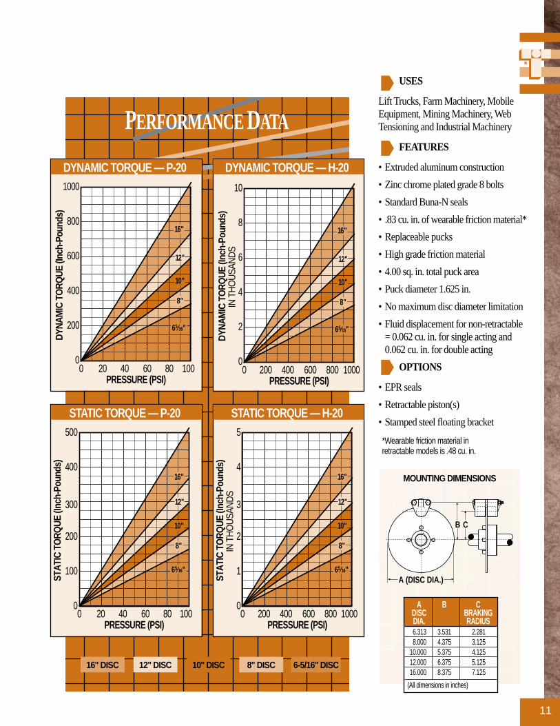
USES
Lift Trucks, Farm Machinery, MobileEquipment, Mining Machinery, WebTensioning and Industrial Machinery.
FEATURES
• Extruded aluminum construction
• Zinc chrome plated grade 5 bolts
• Standard Buna-N seals
• .46 cu. in. of wearable friction material*
• Replaceable pucks
• High grade friction material
• 2.00 sq. in. total puck area
• Puck diameter 1.125 in.
• No maximum disc diameter limitation
• Fluid displacement for non-retractable= 0.029 cu. in. for single acting and0.029 cu. in. for double acting
OPTIONS
• EPR seals
• Retractable piston(s)
• Stamped steel floating bracket
*Wearable friction material inretractable models is .11 cu. in.
PERFORMANCE DATA
MOUNTING DIMENSIONS
0
100
200
300
50
150
250
0 20 40 60 80 100
STAT
IC T
ORQ
UE (I
nch-
Poun
ds)
PRESSURE (PSI)
65⁄16"
8"
10"
12"
16"
STATIC TORQUE — P-10
0
1000
2000
3000
500
1500
2500
0 200 400 600 800 1000
STAT
IC T
ORQ
UE (I
nch-
Poun
ds)
PRESSURE (PSI)
65⁄16"
8"
10"
12"
16"
STATIC TORQUE — H-10
0
100
200
300
400
500
0 20 40 60 80 100
DYNA
MIC
TO
RQUE
(Inc
h-Po
unds
)
PRESSURE (PSI)
65⁄16"
8"
10"
12"
16"
DYNAMIC TORQUE — P-10
0
1000
2000
3000
4000
5000
0 200 400 600 800 1000
DYNA
MIC
TO
RQUE
(Inc
h-Po
unds
)
PRESSURE (PSI)
65⁄16"
8"
10"
12"
16"
DYNAMIC TORQUE — H-10
16" DISC 12" DISC 10" DISC 8" DISC 6-5/16" DISC
A B CDISC BRAKINGDIA. RADIUS6.313 3.469 2.4828.000 4.313 3.325
10.000 5.313 4.32512.000 6.313 5.32516.000 8.313 7.325
(All dimensions in inches)

P-20 & H-20 SERIESALUMINUM
10
MAXIMUM PRESSURE RATING PNEUMATIC = 100 PSIHYDRAULIC = 1000 PSI
SEE PAGE 60 FOR ORDERINGINFORMATION
2.1722.84.30
2.94
G
DIMENSIONAL DATA
SINGLE ACTING (For use with a 5/32", 1/4" or 3/8" Floating Disc)Weight: 1.5 lbs. (.68 kg.)
SINGLE ACTING W/ FLOATING BRACKET(For use with a 5/32" or 1/4" Fixed Disc)
Weight: 2.0 lbs. (.91 kg.)
DOUBLE ACTING (For use with a 5/32", 1/4", 3/8" or 1/2" Fixed Disc)
Weight: 2.0 lbs. (.91 kg.)
FLOATING MOUNT BRACKET
SINGLE ACTINGDOUBLE ACTING
G
2.15
.381.00
.397DIA.(2)
2.31
3.12
.40
1.562.65
1.38
BLEEDER (2)ONLY ON HYDRAULIC ASSEMBLIES
3/8-241.56
B
BLEEDER (4) ONLY ONHYDRAULIC ASSEMBLIES
1/8-27 NPT PORT
3/8-24THREADS
C 1.121.56
E
1/8-27 NPT PORT
F1.12
.12
A D
H2.250
3.122.312
1.25
DISC SIZING EQUATIONS:DYNAMIC TORQUE (IN. LBS.) = 1.44 x BRAKING RADIUS (IN.) x PRESSURE (PSI)
STATIC (PARKING) TORQUE (IN. LBS.) = 0.72 x BRAKING RADIUS (IN.) x PRESSURE (PSI)BRAKING RADIUS (IN.) = [DISC DIAMETER ÷ 2] - 0.875
(All dimensions in inches)
MODEL DISCNUMBER THK A B C D E F G H
PH20 _ A _ _ _ 5/32 4.50 3.41 .281 3.75 2.94 0 4.50 3.53
PH20 _ B _ _ _ 1/4 4.50 3.50 .375 3.75 3.03 .093 4.50 3.53
PH20 _ L _ _ _ 3/8 4.50 3.62 .500 3.75 3.16 .219 4.50 3.53
PH20 _ E _ _ _ 1/2 4.50 3.75 .625 3.75 3.28 .344 4.50 3.53
11
B
A (DISC DIA.)
C
USES
Lift Trucks, Farm Machinery, MobileEquipment, Mining Machinery, WebTensioning and Industrial Machinery
FEATURES
• Extruded aluminum construction
• Zinc chrome plated grade 8 bolts
• Standard Buna-N seals
• .83 cu. in. of wearable friction material*
• Replaceable pucks
• High grade friction material
• 4.00 sq. in. total puck area
• Puck diameter 1.625 in.
• No maximum disc diameter limitation
• Fluid displacement for non-retractable= 0.062 cu. in. for single acting and0.062 cu. in. for double acting
OPTIONS
• EPR seals
• Retractable piston(s)
• Stamped steel floating bracket
*Wearable friction material inretractable models is .48 cu. in.
PERFORMANCE DATA
MOUNTING DIMENSIONS
0
100
200
300
400
500
0 20 40 60 80 100
STAT
IC T
ORQ
UE (I
nch-
Poun
ds)
PRESSURE (PSI)
65⁄16"
8"
10"
12"
16"
STATIC TORQUE — P-20
0
1
2
3
4
5
0 200 400 600 800 1000
STAT
IC T
ORQ
UE (I
nch-
Poun
ds)
IN T
HO
USA
ND
S
PRESSURE (PSI)
65⁄16"
8"
10"
12"
16"
STATIC TORQUE — H-20
0
200
400
600
800
1000
0 20 40 60 80 100
DYNA
MIC
TO
RQUE
(Inc
h-Po
unds
)
PRESSURE (PSI)
65⁄16"
8"
10"
12"
16"
DYNAMIC TORQUE — P-20
0
2
4
6
8
10
0 200 400 600 800 1000
DYNA
MIC
TO
RQUE
(Inc
h-Po
unds
) IN
TH
OU
SAN
DS
PRESSURE (PSI)
65⁄16"
8"
10"
12"
16"
DYNAMIC TORQUE — H-20
16" DISC 12" DISC 10" DISC 8" DISC 6-5/16" DISC
A B CDISC BRAKINGDIA. RADIUS6.313 3.531 2.2818.000 4.375 3.125
10.000 5.375 4.12512.000 6.375 5.12516.000 8.375 7.125
(All dimensions in inches)
P-220 & H-220 SERIESALUMINUM
12
(All dimensions in inches)
2.1722.84.30
2.94
G
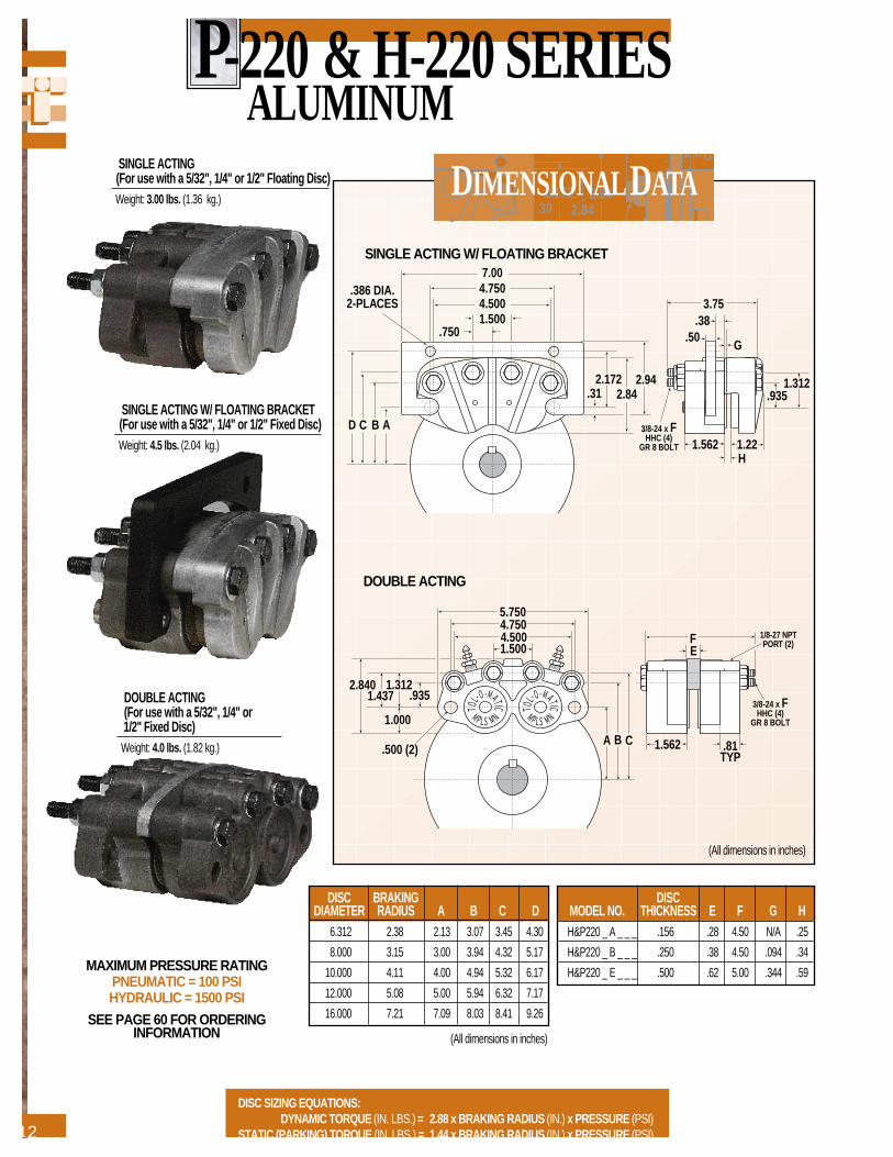
DIMENSIONALDATASINGLE ACTING (For use with a 5/32", 1/4" or 1/2" Floating Disc)Weight: 3.00 lbs. (1.36 kg.)
SINGLE ACTING W/ FLOATING BRACKET(For use with a 5/32", 1/4" or 1/2" Fixed Disc)Weight: 4.5 lbs. (2.04 kg.)
DISC SIZING EQUATIONS:DYNAMIC TORQUE (IN. LBS.) = 2.88 x BRAKING RADIUS (IN.) x PRESSURE (PSI)
STATIC (PARKING) TORQUE (IN. LBS.) = 1.44 x BRAKING RADIUS (IN.) x PRESSURE (PSI)
MAXIMUM PRESSURE RATING PNEUMATIC = 100 PSIHYDRAULIC = 1500 PSI
SEE PAGE 60 FOR ORDERINGINFORMATION
1.5623/8-24 x F
HHC (4)GR 8 BOLT
4.7504.5001.500
.750.38
.50
.386 DIA.2-PLACES
D C B A
1.22
7.00
2.1722.84
1.312.935.31
3.75
2.94
G
H
F 1/8-27 NPTPORT (2)
3/8-24 x FHHC (4)
GR 8 BOLT
A B C
1.000
.9351.312
1.4372.840
1.5004.5004.7505.750
.500 (2)
E
1.562 .81TYP
DOUBLE ACTING (For use with a 5/32", 1/4" or 1/2" Fixed Disc)
Weight: 4.0 lbs. (1.82 kg.)
DISC BRAKINGDIAMETER RADIUS A B C D
6.312 2.38 2.13 3.07 3.45 4.30
8.000 3.15 3.00 3.94 4.32 5.17
10.000 4.11 4.00 4.94 5.32 6.17
12.000 5.08 5.00 5.94 6.32 7.17
16.000 7.21 7.09 8.03 8.41 9.26
DISCMODEL NO. THICKNESS E F G HH&P220 _ A _ _ _ .156 .28 4.50 N/A .25
H&P220 _ B _ _ _ .250 .38 4.50 .094 .34
H&P220 _ E _ _ _ .500 .62 5.00 .344 .59
SINGLE ACTING W/ FLOATING BRACKET
DOUBLE ACTING
(All dimensions in inches)
13
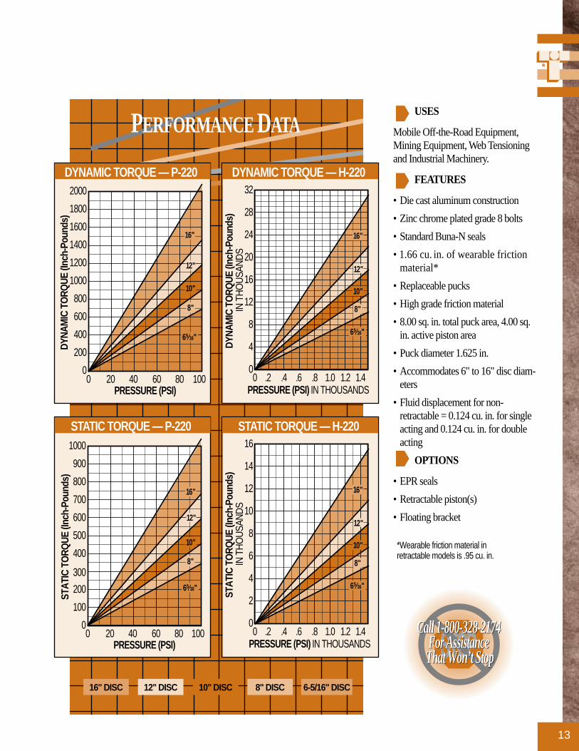
USES
Mobile Off-the-Road Equipment,Mining Equipment, Web Tensioningand Industrial Machinery.
FEATURES
• Die cast aluminum construction
• Zinc chrome plated grade 8 bolts
• Standard Buna-N seals
• 1.66 cu. in. of wearable frictionmaterial*
• Replaceable pucks
• High grade friction material
• 8.00 sq. in. total puck area, 4.00 sq.in. active piston area
• Puck diameter 1.625 in.
• Accommodates 6" to 16" disc diam-eters
• Fluid displacement for non-retractable = 0.124 cu. in. for singleacting and 0.124 cu. in. for doubleacting
OPTIONS
• EPR seals
• Retractable piston(s)
• Floating bracket
*Wearable friction material inretractable models is .95 cu. in.
PERFORMANCE DATA
0
100
200
300
400
500
600
700
800
900
1000
0 20 40 60 80 100
STAT
IC T
ORQ
UE (I
nch-
Poun
ds)
PRESSURE (PSI)
65⁄16"
8"
10"
12"
16"
STATIC TORQUE — P-220
0
2
4
6
8
10
12
14
16
0 .2 .4 .6 .8 1.0 1.2 1.4
STAT
IC T
ORQ
UE (I
nch-
Poun
ds)
IN T
HO
USA
ND
S
PRESSURE (PSI) IN THOUSANDS
65⁄16"
8"
10"
12"
16"
STATIC TORQUE — H-220
0
200
400
600
800
1000
1200
1400
1600
1800
2000
0 20 40 60 80 100
DYNA
MIC
TO
RQUE
(Inc
h-Po
unds
)
PRESSURE (PSI)
65⁄16"
8"
10"
12"
16"
DYNAMIC TORQUE — P-220
0
4
8
12
16
20
24
28
32
0 .2 .4 .6 .8 1.0 1.2 1.4
DYNA
MIC
TO
RQUE
(Inc
h-Po
unds
) IN
TH
OU
SAN
DS
PRESSURE (PSI) IN THOUSANDS
65⁄16"
8"
10"
12"
16"
DYNAMIC TORQUE — H-220
STOP Call 1-800-328-2174
For Assistance That Won’t Stop
Call 1-800-328-2174 For Assistance That Won’t Stop
16" DISC 12" DISC 10" DISC 8" DISC 6-5/16" DISC

H-220I SERIESCAST IRON
14
USES
Mobile Off-the-Road Equipment andMining Machinery.
FEATURES
• Cast ductile iron housings
• Zinc chrome plated grade 8 bolts
• Standard Buna-N seals
• 2.35 cu. in. of wearable frictionmaterial
• Replaceable pucks
• High grade friction material
• 9.4 sq. in. total puck area
• Piston diameter 1.625 in.
• Accommodates 6" to 16" disc diameters
• Fluid displacement for non-retractable = 0.124 cu. in. for singleacting and 0.124 cu. in. for doubleacting
OPTIONS
• EPR seals
• Steel floating bracket
PERFORMANCE DATA
0
2
4
6
8
10
12
14
16
0 .2 .4 .6 .8 1.0 1.2 1.4
STAT
IC T
ORQ
UE (I
nch-
Poun
ds)
IN T
HO
USA
ND
S
PRESSURE (PSI) IN THOUSANDS
65⁄16"
8"
10"
12"
16"
STATIC TORQUE — H-220I
0
4
8
12
16
20
24
28
32
0 .2 .4 .6 .8 1.0 1.2 1.4
DYNA
MIC
TO
RQUE
(Inc
h-Po
unds
) IN
TH
OU
SAN
DS
PRESSURE (PSI) IN THOUSANDS
65⁄16"
8"
10"
12"
16"
DYNAMIC TORQUE — H-220I
SINGLE ACTING (For use with a 5/32", 1/4", 3/8" or1/2" Floating Disc)Weight: 9.00 lbs. (4.08 kg.)
SINGLE ACTING W/ FLOATING BRACKET(For use with a 5/32", 1/4", 3/8" or1/2" Fixed Disc)Weight: 10.5 lbs.(4.76 kg.)
DISC SIZING EQUATIONS:DYNAMIC TORQUE (IN. LBS.) = 2.88 x BRAKING RADIUS (IN.) x PRESSURE (PSI)
STATIC (PARKING) TORQUE (IN. LBS.) = 1.44 x BRAKING RADIUS (IN.) x PRESSURE (PSI)
MAXIMUM PRESSURE RATING HYDRAULIC = 1500 PSI
SEE PAGE 61 FOR ORDERINGINFORMATION
DOUBLE ACTING (For use with a 5/32", 1/4", 3/8" or 1/2" Fixed Disc)
Weight: 12.0 lbs. (5.40 kg.)
16" DISC 12" DISC 10" DISC 8" DISC 6-5/16" DISC

15
(All dimensions in inches)
2.1722.84.30
2.94
G
DIMENSIONAL DATA
4.7504.5001.500
.750.50
.386 DIA.2-PLACES
DC
BA
7.00
2.62
F
5.75
.935 1.312
1.00
2.172
1.16
2.00
1.25 E
4.75
1/8-27 NPTPORT (2)
3/8-24 x4-1/2 HHC(4) GR 8
BOLT FORSA, SB,SL, SE
MODELS1.56
.68
.905
4.7504.5001.500
.750
CB
A
F
5.75
.935 1.312
1.00
1.16
1.97
G 1/8-27 NPTPORT (2)
3/8-24 x HHHC (4)
GR 8 BOLT
1.56
1.84
1.971.561.16
DISC BRAKINGDIAMETER RADIUS A B C D
6.312 2.38 2.13 3.07 3.45 4.30
8.000 3.15 3.00 3.94 4.32 5.17
10.000 4.11 4.00 4.94 5.32 6.17
12.000 5.08 5.00 5.94 6.32 7.71
16.000 7.21 7.09 8.03 8.41 9.26
DISC HMODEL NO. THICKNESS E F G BOLT LNGH220SACI _ .156 .83 3.45 4.25 4.00
H220DACI _ .156 N/A 4.15 5.25 5.00
H220SBCI _ .250 .92 3.54 4.25 4.00
H220DBCI _ .250 N/A 4.24 5.25 5.00
H220SLCI _ .375 1.05 3.67 4.25 4.00
H220DLCI _ .375 N/A 4.37 5.75 5.50
H220SECI _ .500 1.17 3.79 4.75 4.50
H220DECI _ .500 N/A 4.50 6.25 6.00
H220D_ CI 1.200 N/A 5.20 6.75 6.50
SINGLE ACTING W/ FLOATING BRACKET
DOUBLE ACTING
(All dimensions in inches)

H-440 SERIESDUCTILE IRON
16
USES
Mobile Off-the Road Equipment andMining Machinery
FEATURES
• Cast ductile iron housings
• Five bleed fitting positions
• Zinc chrome plated grade 8 bolts
• Standard Buna-N seals
• 4.15 cu. in. of wearable frictionmaterial
• Replaceable pucks
• High grade friction material
• 8.30 sq. in. total puck area
• Puck diameter 2.37 in.
• Steel pistons
• No maximum disc diameter limitation
• Fluid displacement for .03 inch clear-ance = 0.147 cu. in. for single actingand 0.147 cu. in. for double acting
OPTIONS
• EPR seals
PERFORMANCE DATA
0
5
10
15
20
25
30
0 .2 .4 .6 .8 1.0 1.2 1.4
STAT
IC T
ORQ
UE (I
nch-
Poun
ds)
IN T
HO
USA
ND
S
PRESSURE (PSI) IN THOUSANDS
10"
16"
20"
24"
12"
STATIC TORQUE — H-440
0
5
10
15
20
25
30
35
40
45
50
55
0 .2 .4 .6 .8 1.0 1.2 1.4
DYNA
MIC
TO
RQUE
(Inc
h-Po
unds
) IN
TH
OU
SAN
DS
PRESSURE (PSI) IN THOUSANDS
10"
16"
20"
24"
12"
DYNAMIC TORQUE — H-440
16" DISC 12" DISC 10" DISC24" DISC 20" DISC24" DISC 20" DISC
SINGLE ACTING (For use with a 3/8", 1/2", 1", 1-1/4" or 1-1/2" Floating Disc)
Weight: 23.0 lbs. (10.43 kg.)
DISC SIZING EQUATIONS:DYNAMIC TORQUE (IN. LBS.) = 3.19 x BRAKING RADIUS (IN.) x PRESSURE (PSI)
STATIC (PARKING) TORQUE (IN. LBS.) = 1.905 x BRAKING RADIUS (IN.) x PRESSURE (PSI)BRAKING RADIUS (IN.)= [DISC DIAMETER ÷ 2] - 1.250
MAXIMUM PRESSURE RATING HYDRAULIC = 1500 PSI
SEE PAGE 61 FOR ORDERINGINFORMATION
DOUBLE ACTING (For use with a 3/8", 1/2", 1", 1-1/4" or 1-1/2" Fixed Disc)
Weight: 27.0 lbs. (12.25 kg.)
NOTE: Available Tol-O-Matic Disc Sizes 65⁄16", 8", 10", 12", and 16"

17
(All dimensions in inches)
2.1722.84.30
2.94
G
DIMENSIONAL DATA
1.43R 1.56R
2.3124.6255.88
1.625
4.20R14° 14°
1.249(2)1/8-27NPT
SPOTFACEDIA.1.25
(2) 1/2-13x5 GR5MOUNTING
BOLTS TORQUETO 40 FT LBS. AT
MOUNTING .50.38
.88
F
2.31H
EG
(2) 1/2-13x5 GR5MOUNTING
BOLTS TORQUETO 40 FT LBS. AT
MOUNTING
.50.38 .88
2.37
J1.061.06 MOUNTING
SURFACE
MOUNTINGSURFACE
SPACE FOROPTIONALMOUNTING
WITH ABRACKET
(3) 1/2-13x?(GRADE 8)
BOLTS TORQUETO 50 FT LBS.AT MOUNTING
AB
.7241.035
FLOATMOUNTINGSPACE FORBRACKET
C D
OPTIONALSPACER
SINGLE ACTING DOUBLE ACTING
(All dimensions in inches)
DISC BOLTMODEL NO. THICKNESS LENGTH C D E F G H J
H440 _ LC_ .375 6.50 .83 .52 .56 .12 2.12 5.18 5.18
H440 _ EC_ .500 7.00 .77 .46 .63 .06 2.19 5.68 5.31
H440 _ NC_ 1.000 7.50 .77 .46 1.13 .06 2.62 6.18 5.81
H440 _ OC_ 1.250 7.50 .77 .46 1.38 .06 2.87 6.18 6.06
H440 _ QC_ 1.500 8.00 .77 .46 1.63 .06 3.12 6.68 6.31
BDISC DIA. A BRAKING RADIUS
10.00 5.315 3.75
12.00 6.315 4.75
16.00 8.315 6.75
20.00 10.315 8.75
24.00 12.315 10.75
STOP Call 1-800-328-2174
For Assistance That Won’t Stop
Call 1-800-328-2174 For Assistance That Won’t Stop

H-441 SERIESDUCTILE IRON
18
USES
Mobile Equipment and MiningMachinery
FEATURES
• Cast ductile iron housings
• Zinc chrome plated grade 5 bolts
• Standard Buna-N seals
• 3.71 cu. in. of wearable frictionmaterial
• Replaceable pucks
• High grade friction material
• 9.14 sq. in. total puck area
• Puck diameter 2.50 in.
• 4.91 sq. in. piston area
• No maximum disc diameter limita-tion
• Fluid displacement for .03 inch clear-ance = 0.147 cu. in. for double acting
• Maximum combined allowable wear= 0.812 in.
OPTIONS
• EPR seals
PERFORMANCE DATA
0
5
10
15
20
25
30
35
0 .2 .4 .6 .8 1.0 1.2 1.4
STAT
IC T
ORQ
UE (I
nch-
Poun
ds)
IN T
HO
USA
ND
S
PRESSURE (PSI) IN THOUSANDS
10"
16"
20"
24"
12"
STATIC TORQUE — H-441
0
5
10
15
20
25
30
35
40
45
50
55
0 .2 .4 .6 .8 1.0 1.2 1.4
DYNA
MIC
TO
RQUE
(Inc
h-Po
unds
) IN
TH
OU
SAN
DS
PRESSURE (PSI) IN THOUSANDS
10"
16"
20"
24"
12"
DYNAMIC TORQUE — H-441
DISC SIZING EQUATIONS:DYNAMIC TORQUE (IN. LBS.) = 3.53 x BRAKING RADIUS (IN.) x PRESSURE (PSI)
STATIC (PARKING) TORQUE (IN. LBS.) = 2.11 x BRAKING RADIUS (IN.) x PRESSURE (PSI)BRAKING RADIUS (IN.) = [DISC DIAMETER ÷ 2] - 1.31
MAXIMUM PRESSURE RATING HYDRAULIC = 1500 PSI
SEE PAGE 62 FOR ORDERINGINFORMATION
DOUBLE ACTING (For use with a Fixed Disc)
Weight: 17.0 lbs. (7.71 kg.)
NOTE: Available Tol-O-Matic Disc Sizes 65⁄16", 8", 10", 12", and 16"
16" DISC 12" DISC 10" DISC24" DISC 20" DISC24" DISC 20" DISC

19
(All dimensions in inches)
2.1722.84.30
2.94
G
DIMENSIONAL DATA
BA
1.81 1.25
.48 1.1252.250
2.004.00
1.56
2.005.12
1.56R1/8-27 NPTFINLET PORT
SPACER BY CUSTOMER TO BE 3/8"THICKER THAN DISC
5/8-18 x 5.50LG GR5 HHC BOLT (FOR DISCTHICKNESSES UP TO 1/2", LONGER BOLTS
ARE AVAILABLE)
1/8-27NPTFINLETPORT
DOUBLE ACTING
(All dimensions in inches)
BDISC DIA. A BRAKING RADIUS
10.00 5.69 3.69
12.00 6.69 4.69
16.00 8.69 6.69
20.00 10.69 8.69
24.00 12.69 10.69
STOP Call 1-800-328-2174
For Assistance That Won’t Stop
Call 1-800-328-2174 For Assistance That Won’t Stop

H-960 SERIESDUCTILE IRON
20
USES
Mobile Off-the-Road Equipment,Mining Machinery and HeavyIndustrial Machinery
FEATURES
• Cast ductile iron housings
• Parkerized grade 5 bolts
• Standard Buna-N seals
• 8.0 cu. in. of wearable frictionmaterial
• Easily replaceable pads
• High grade friction material
• 32.0 sq. in. total pad area
• Piston diameter 3.50 in.
• Accommodates 12" to 18" inch discdiameters
• Fluid displacement = 0.576 cu. in. fordouble acting
• Maximum combined allowablewear=0.50 in.
OPTIONS
• EPR seals
PERFORMANCE DATA
0
5
10
15
20
25
30
35
40
45
0 .2 .4 .6 .8 1.0 1.2 1.4
STAT
IC T
ORQ
UE (I
nch-
Poun
ds)
IN T
HO
USA
ND
S
PRESSURE (PSI) IN THOUSANDS
12"
18"
16"
14"
STATIC TORQUE — H-960
0
10
20
30
40
50
60
70
80
0 .2 .4 .6 .8 1.0 1.2 1.4
DYNA
MIC
TO
RQUE
(Inc
h-Po
unds
) IN
TH
OU
SAN
DS
PRESSURE (PSI) IN THOUSANDS
12"
18"
16"
14"
DYNAMIC TORQUE — H-960
16" DISC 14" DISC 12" DISC18" DISC
DISC SIZING EQUATIONS:DYNAMIC TORQUE (IN. LBS.) = 6.92 x BRAKING RADIUS (IN.) x PRESSURE (PSI)
STATIC (PARKING) TORQUE (IN. LBS.) = 4.04 x BRAKING RADIUS (IN.) x PRESSURE (PSI)BRAKING RADIUS (IN.) = [DISC DIAMETER ÷ 2] - 1.60
MAXIMUM PRESSURE RATING HYDRAULIC = 1500 PSI
(Intermittent Duty)HYDRAULIC = 1000 PSI
(Continuous Duty)
SEE PAGE 62 FOR ORDERINGINFORMATION
DOUBLE ACTING (For use with a 1/2" Fixed Disc)
Weight: 35.0 lbs. (15.88 kg.)
NOTE: Available Tol-O-Matic Disc Sizes 65⁄16", 8", 10", 12", and 16"

21
2.1722.84.30
2.94
G
DIMENSIONAL DATA
C
E1.91D
.50(TYP)
1.625
3.2503.250
6.5008.375
6.25(REF)
2.311.56
2.25
.66DIA.(2)
1/8-27NPTFPORT
5/8-18 x4.00 LG
BOLTS (2)
3.06R9.00R
.32
A
B
DOUBLE ACTING
(All dimensions in inches)
DISCMODEL NO. THICKNESS C D E
H960DECI .500 4.44 3.44 .620
H960DECIG .500 4.44 3.44 .620
H960DOCI 1.125 5.07 4.07 1.125
H960DOCIG 1.125 5.07 4.07 1.125
BDISC DIA. A BRAKING RADIUS
12.00 6.712 4.40
14.00 7.712 5.40
16.00 8.712 6.40
18.00 9.712 7.40
STOP Call 1-800-328-2174
For Assistance That Won’t Stop
Call 1-800-328-2174 For Assistance That Won’t Stop
(All dimensions in inches)

H/ME-20 SERIESALUMINUM
22
AB
DISC DIA.
MAXIMUM PRESSURE RATING HYDRAULIC = 1000 PSI
MAXIMUM LEVER FORCE MECHANICAL = 200 LBS.
SEE PAGE 62 FOR ORDERINGINFORMATION
DISC A BDIA. BRAKING
RADIUS6.313 3.531 2.2818.000 4.375 3.125
10.000 5.375 4.12512.000 6.375 5.12516.000 8.375 7.125
(All dimensions in inches)
2.1722.84.30
2.94
G
DIMENSIONAL DATA
MOUNTING DIMENSIONS
B
“M” MACHINED CAM MAY BE MOUNTEDIN ANY OF FOUR POSITIONS
2.250
D
3.12
1.121.75
1.00
1.383.53
G
1.01
1.250
E
.32R .265DIA. (2)
2.50
.406R
.531DIA.
3.50
.397DIA.
2.312
“L” LEVER ARM MAY BE MOUNTED INEITHER OF TWO POSITIONS
1.75
.32R
.265DIA.
“S” LEVERARM
MAY BEMOUNTEDIN EITHEROF TWO
POSITIONS
.75
1.37
.56
1.50
1.25CFA 3.86
1/8-27 NPTPORT
DISC SIZING EQUATIONS (HYDRAULIC):DYNAMIC TORQUE (IN. LBS.) = 1.44 x BRAKING RADIUS (IN.) x PRESSURE (PSI)
STATIC (PARKING) TORQUE (IN. LBS.) = 0.72 x BRAKING RADIUS (IN.) x PRESSURE (PSI)BRAKING RADIUS (IN.) = [DISC DIAMETER ÷ 2] - 0.875
DISC SIZING EQUATIONS (MECHANICAL):STATIC (PARKING) TORQUE (IN. LBS.) = (L) 2.69 x BRAKING RADIUS (IN.) x LEVER FORCE (LBS.)STATIC (PARKING) TORQUE (IN. LBS.) = (M&S) 1.345 x BRAKING RADIUS (IN.) x LEVER FORCE (LBS.)
BRAKING RADIUS (IN.) = [DISC DIAMETER ÷ 2] - 0.875
(All dimensions in inches)
“L” LONG LEVER (3.50") (For use with a 5/32" or 1/4" Floating Disc)Weight: 1.50 lbs. (.68 kg.)
“L” LONG LEVER (3.50") WITH FLOATING BRACKET(For use with a 5/32" or 1/4" Fixed Disc)Weight: 2.25 lbs. (1.02 kg.)
“M” MACHINED CAM LEVER (1.75") (For use with a 5/32" or 1/4" Floating Disc)Weight: 1.50 lbs. (.68 kg.)
“M” MACHINED CAM LEVER (1.75") WITH FLOATING BRACKET(For use with a 5/32" or 1/4" Fixed Disc)Weight: 2.25 lbs. (1.02 kg.)
“S” SHORT LEVER (1.75") (For use with a 5/32" or 1/4" Floating Disc)Weight: 1.50 lbs. (.68 kg.)
“S” SHORT LEVER (1.75") WITH FLOATING BRACKET(For use with a 5/32" or 1/4" Fixed Disc)Weight: 2.25 lbs. (1.02 kg.)
MODEL A B C D E F GHME20MAFG .61 .105 .25 – 6.49 1.38 4.50HME20MBFG .61 .105 .34 .094 6.58 1.47 4.50HME20SAFG .80 .164 .25 – 6.49 1.38 4.50HME20SBFG .80 .164 .34 .094 6.49 1.47 4.50HME20LAFG .80 .164 .25 – 6.49 1.38 4.50HME20LBFG .80 .164 .34 .094 6.49 1.47 4.50HME20MAG .61 .105 .25 – 5.99 1.38 3.75HME20MBG .61 .105 .34 .094 5.99 1.47 3.75HME20SAG .80 .164 .25 – 5.99 1.38 3.75HME20SBG .80 .164 .34 .094 6.08 1.47 3.75HME20LAG .80 .164 .25 – 5.99 1.38 3.75HME20LBG .80 .164 .34 .094 5.99 1.47 3.75

23
PERFORMANCE DATA
0
1
2
3
4
5
0 50 100 150 200 0 100 200 300 400
STA
TIC
TO
RQ
UE
(Inch
-Pou
nds)
IN
TH
OU
SAN
DS
LEVER FORCE (Pounds)
65⁄16"
8"
10"
12"
16"
Lever Size 3.5" 1.75"
STATIC TORQUE — H/ME-20
0
1
2
3
4
5
0 200 400 600 800 1000
STAT
IC T
ORQ
UE (I
nch-
Poun
ds)
IN T
HO
USA
ND
S
PRESSURE (PSI)
65⁄16"
8"
10"
12"
16"
STATIC TORQUE — H/ME-20
0
2
4
6
8
10
0 50 100 150 200 0 100 200 300 400
DYN
AM
IC T
OR
QU
E (In
ch-P
ound
s)
IN T
HO
USA
ND
S
LEVER FORCE (Pounds)
65⁄16"
8"
10"
12"
16"
Lever Size 3.5" 1.75"
DYNAMIC TORQUE — H/ME-20
0
2
4
6
8
10
0 200 400 600 800 1000
DYNA
MIC
TO
RQUE
(Inc
h-Po
unds
) IN
TH
OU
SAN
DS
PRESSURE (PSI)
65⁄16"
8"
10"
12"
16"
DYNAMIC TORQUE — H/ME-20
USES
Lift Trucks, Farm Machinery,Mobile Equipment, MiningMachinery and Industrial Machinery
FEATURES
• Cast aluminum construction
• Zinc chrome plated grade 5 bolts
• Standard EPR seals
• .83 cu. in. of wearable frictionmaterial
• Replaceable pucks
• High grade friction material
• 4.00 sq. in. total puck area
• Puck diameter 1.625 in.
• No maximum disc diameter limi-tation
• Fluid displacement = 0.062 cu. in.
OPTIONS
• Buna-N seals
• Stamped steel floating bracket
16" DISC 12" DISC 10" DISC 8" DISC 6-5/16" DISC
STOP Call 1-800-328-2174
For Assistance That Won’t Stop
Call 1-800-328-2174 For Assistance That Won’t Stop

H/ME-220 SERIESALUMINUM
24
(All dimensions in inches)
2.1722.84.30
2.94
G
DIMENSIONAL DATA
SINGLE ACTING W/ FLOAT PIN HOLES(For use with a 5/32", 1/4", 3/8" or 1/2" Disc)Weight: 6.00 lbs. (2.72 kg.)
.94(2)
4.500
1.500.750
1.56.50
1.00
1.31(2).94(2)
.50(2)
C
B
D
2.84
A
DISCCENTER LINE
1.615 DIA.PUCK (2)
2.16
.462MAX.1.16
(3)
1.472.25
1.38
1/8 NPTPORT
3.39(2)2.25
1/8 NPTBLEEDERSCREW (2)
.50(2)
4.00 2.38(2)
5.75CL
.397 DIA.THRU
.38RAD.
.500 / .502DIA. THRU
MAXIMUM PRESSURE RATING HYDRAULIC = 1500 PSI
MAXIMUM LEVER FORCE MECHANICAL = 580 LBS.
SEE PAGE 62 FOR ORDERING INFORMATION
DISC SIZING EQUATIONS (HYDRAULIC):DYNAMIC TORQUE (IN. LBS.) = 2.88 x BRAKING RADIUS (IN.) x PRESSURE (PSI)
STATIC (PARKING) TORQUE (IN. LBS.) = 1.44 x BRAKING RADIUS (IN.) x PRESSURE (PSI)DISC SIZING EQUATIONS (MECHANICAL):
DYNAMIC TORQUE (IN. LBS.) = 7.45 x BRAKING RADIUS(IN.) x LEVER FORCE(LBS.)STATIC (PARKING) TORQUE (IN. LBS.) = 3.725 x BRAKING RADIUS(IN.) x LEVER FORCE(LBS.)
“D” DISCMODEL NO. B C THICKNESSHME220ACG .094 3.124 .156
HME220BCG .188 3.218 .250
HME220LCG .313 3.343 .375
HME220ECG .438 3.468 .500
ADISC BRAKING
DIAMETER RADIUS6.312 2.13
8.000 3.00
10.000 4.00
12.000 5.00
16.000 7.03 (All dimensions in inches)

25
USES
Mobile Off-the-Road Equipment,Mining Equipment and IndustrialMachinery
FEATURES
• Cast aluminum construction
• Zinc chrome plated grade 8 bolts
• Standard EPR seals
• 1.66 cu. in. of wearable frictionmaterial
• Replaceable pucks
• High grade friction material
• 8.00 sq. in. total puck area, 4.00 sq.in. active piston area
• Puck diameter 1.610 in.
• Accommodates 6" to 16" disc diam-eters
• Fluid displacement = 0.124 cu. in.
OPTIONS
• Buna-N seals
PERFORMANCE DATA
0
2
4
6
8
10
12
14
16
0 100 200 300 400 500 600
STAT
IC T
ORQ
UE (I
nch-
Poun
ds)
IN T
HO
USA
ND
S
LEVER FORCE (Pounds)
65⁄16"
8"
10"
12"
16"
STATIC TORQUE — H/ME-220
0
2
4
6
8
10
12
14
16
0 .2 .4 .6 .8 1.0 1.2 1.4
STAT
IC T
ORQ
UE (I
nch-
Poun
ds)
IN T
HO
USA
ND
S
PRESSURE (PSI) IN THOUSANDS
65⁄16"
8"
10"
12"
16"
STATIC TORQUE — H/ME-220
0
4
8
12
16
20
24
28
32
0 100 200 300 400 500 600
DYNA
MIC
TO
RQUE
(Inc
h-Po
unds
) IN
TH
OU
SAN
DS
LEVER FORCE (Pounds)
65⁄16"
8"
10"
12"
16"
DYNAMIC TORQUE — H/ME-220
0
4
8
12
16
20
24
28
32
0 .2 .4 .6 .8 1.0 1.2 1.4
DYNA
MIC
TO
RQUE
(Inc
h-Po
unds
) IN
TH
OU
SAN
DS
PRESSURE (PSI) IN THOUSANDS
65⁄16"
8"
10"
12"
16"
DYNAMIC TORQUE — H/ME-220
16" DISC 12" DISC 10" DISC 8" DISC 6-5/16" DISC
STOP Call 1-800-328-2174
For Assistance That Won’t Stop
Call 1-800-328-2174 For Assistance That Won’t Stop

ME-10 SERIESALUMINUM
26
USES
Lift Trucks, Farm Machinery,Industrial Machinery and Light MobileEquipment
FEATURES
• Aluminum die cast construction
• Zinc chrome plated grade 5 bolts
• Floating bracket features zinc platedsteel bushings
• .46 cu. in. of wearable frictionmaterial
• Replaceable pucks
• High grade friction material
• 2.00 sq. in. total puck area
• Puck diameter 1.125 in.
• Machined lever features heat treatedone piece lever/cam or machine “V”notch cam
• No maximum disc diameter limita-tion
OPTIONS
• Stamped steel floating bracket mount
• Additional lever positions may beavailable, consult factory
PERFORMANCE DATA
0
1
2
3
4
5
0 50 100 150 200 0 100 200 300 400
STA
TIC
TO
RQ
UE
(Inch
-Pou
nds)
IN
TH
OU
SAN
DS
LEVER FORCE (Pounds)
65⁄16"
8"
10"
12"
16"
Lever Size 3.5" 1.75"
STATIC TORQUE — ME-10
0
2
4
6
8
10
0 50 100 150 200 0 100 200 300 400
DYN
AM
IC T
OR
QU
E (In
ch-P
ound
s)
IN T
HO
USA
ND
S
LEVER FORCE (Pounds)
65⁄16"
8"
10"
12"
16"
Lever Size 3.5" 1.75"
DYNAMIC TORQUE — ME-10
“L” LONG LEVER (3.50") (For use with a 5/32"or 1/4" Floating Disc)Weight: .75 lbs. (.34 kg.)
“L” LONG LEVER (3.50") WITH FLOATING BRACKET(For use with a 5/32"or 1/4" Fixed Disc)Weight: 1.25 lbs. (.56 kg.)
“M” MACHINED CAM LEVER (1.75") (For use with a 5/32"or 1/4" Floating Disc)Weight: .75 lbs. (.34 kg.)
“M” MACHINED CAM LEVER (1.75") WITH FLOATING BRACKET(For use with a 5/32"or 1/4" Fixed Disc)Weight: 1.50 lbs. (.68 kg.)
DISC SIZING EQUATIONS (L) 3.50" LEVER:DYNAMIC TORQUE (IN. LBS.) = 5.38 x BRAKING RADIUS (IN.) x LEVER FORCE (LBS.)
STATIC (PARKING) TORQUE (IN. LBS.) = 2.69 x BRAKING RADIUS (IN.) x LEVER FORCE (LBS.)DISC SIZING EQUATIONS (M & S) 1.75" LEVER:
DYNAMIC TORQUE (IN. LBS.) = 2.69 x BRAKING RADIUS (IN.) x LEVER FORCE (LBS.)STATIC (PARKING) TORQUE (IN. LBS.) = 1.345 x BRAKING RADIUS (IN.) x LEVER FORCE (LBS.)
BRAKING RADIUS (IN.)= [DISC DIAMETER ÷ 2] - .625
“S” SHORT LEVER (1.75") (For use with a 5/32"or 1/4" Floating Disc)Weight: .75 lbs. (.34 kg.)
“S” SHORT LEVER (1.75") WITH FLOATING BRACKET(For use with a 5/32"or 1/4" Fixed Disc)Weight: 1.25 lbs. (.56 kg.)
MAXIMUM LEVER FORCE (L) 3.50" LEVER = 225 LBS.
(M & S) 1.75" LEVER = 450 LBS.
SEE PAGE 62 FOR ORDERINGINFORMATION
16" DISC 12" DISC 10" DISC 8" DISC 6-5/16" DISC

27
2.1722.84.30
2.94
G
DIMENSIONAL DATA
2.1722.84 .93.30
2.94
G
MOUNTING DIMENSIONS
1.625
.69
2.31
.69
.69 .94
2.25
.38
.937
B
“M” MACHINED CAM MAY BE MOUNTEDIN ANY OF FOUR POSITIONS
1.121.75
.32R.265
DIA. (2)2.50
.406R
.531DIA.
3.50
.397DIA.
“L” LEVER ARM MAY BE MOUNTED INEITHER OF TWO POSITIONS
1.75
.32R
.265DIA.
“S” LEVERARM
MAY BEMOUNTEDIN EITHEROF TWO
POSITIONS“M” #12
GAGE (.104)
“S” & “L”#8 GAGE
(.164)
5/16-24A SPACER
1.625
.69
2.50
.69
.69 .94.98
1.973.00
1.00
.937
B
.332DIA. (2) .28
“M” MACHINED CAM MAY BE MOUNTEDIN ANY OF FOUR POSITIONS
1.121.75
.32R.265
DIA. (2)2.50
.406R
.531DIA.
3.50
.397DIA.
“L” LEVER ARM MAY BE MOUNTED INEITHER OF TWO POSITIONS
1.75
.32R
.265DIA.
“S” LEVERARM
MAY BEMOUNTEDIN EITHEROF TWO
POSITIONS“M” #12
GAGE (.104)
“S” & “L”#8 GAGE
(.164)
A SPACER
FLOATING MOUNT FOR USEWITH FIXED DISC ME-10(L,M,S)AF
FIXED MOUNT FOR USE WITHFLOATING DISC ME-10(L,M,S)A
(All dimensions in inches)
BDISC DIA. A BRAKING RADIUS C D E
6.312 3.469 2.531 .938 .750 1.625
8.000 4.312 3.375 .938 .750 1.625
10.000 5.312 4.375 .938 .750 1.625
12.000 6.312 5.375 .938 .750 1.625
16.000 8.312 7.375 .938 .750 1.625
(All dimensions in inches)
ED
AB
C
DISC DIA.
DISC AMODEL NO. THK SPACER B
ME10(S,L,M)A(F) 5/32 N/A 3.13
ME10(S,L,M)B(F) 1/4 .093 3.22

ME-20 SERIESALUMINUM
28
USES
Lift Trucks, Farm Machinery,Industrial Machinery and Light MobileEquipment
FEATURES
• Aluminum die cast construction
• Zinc chrome plated grade 5 bolts
• Floating bracket features zinc platedsteel bushings
• .83 cu. in. of wearable frictionmaterial
• Replaceable pucks
• High grade friction material
• 4.00 sq. in. total puck area,
• Puck diameter 1.625 in.
• Machined lever features heat treatedone piece lever/cam or machine “V”notch cam
• No maximum disc diameter limita-tion
OPTIONS
• Stamped steel floating bracket mount
• Additional lever positions may beavailable, consult factory
PERFORMANCE DATA
0
1
2
3
4
5
0 50 100 150 200 0 100 200 300 400
STA
TIC
TO
RQ
UE
(Inch
-Pou
nds)
IN
TH
OU
SAN
DS
LEVER FORCE (Pounds)
65⁄16"
8"
10"
12"
16"
Lever Size 3.5" 1.75"
STATIC TORQUE — ME-20
0
2
4
6
8
10
0 50 100 150 200 0 100 200 300 400
DYN
AM
IC T
OR
QU
E (In
ch-P
ound
s)
IN T
HO
USA
ND
S
LEVER FORCE (Pounds)
65⁄16"
8"
10"
12"
16"
Lever Size 3.5" 1.75"
DYNAMIC TORQUE — ME-20
“L” LONG LEVER (3.50") (For use with a 5/32" or 1/4" Floating Disc)Weight: 1.50 lbs. (.68 kg.)
“L” LONG LEVER (3.50") WITH FLOATING BRACKET(For use with a 5/32" or 1/4" Fixed Disc)Weight: 2.25 lbs. (1.02 kg.)
“M” MACHINED LEVER (1.75") (For use with a 5/32" or 1/4" Floating Disc)Weight: 1.50 lbs. (.68 kg.)
“M” MACHINED LEVER (1.75") WITH FLOATING BRACKET(For use with a 5/32" or 1/4" Fixed Disc)Weight: 2.25 lbs. (1.02 kg.)
DISC SIZING EQUATIONS (L) 3.50" LEVER:DYNAMIC TORQUE (IN. LBS.) = 5.38 x BRAKING RADIUS (IN.) x LEVER FORCE (LBS.)
STATIC (PARKING) TORQUE (IN. LBS.) = 2.69 x BRAKING RADIUS (IN.) x LEVER FORCE (LBS.)DISC SIZING EQUATIONS (M & S) 1.75" LEVER:
DYNAMIC TORQUE (IN. LBS.) = 2.69 x BRAKING RADIUS (IN.) x LEVER FORCE (LBS.)STATIC (PARKING) TORQUE (IN. LBS.) = 1.345 x BRAKING RADIUS (IN.) x LEVER FORCE (LBS.)
BRAKING RADIUS (IN.) = [DISC DIAMETER ÷ 2] - .875
“S” SHORT LEVER (1.75") (For use with a 5/32" or 1/4" Floating Disc)Weight: 1.50 lbs. (.68 kg.)
“S” SHORT LEVER (1.75") WITH FLOATING BRACKET(For use with a 5/32" or 1/4" Fixed Disc)Weight: 2.25 lbs. (1.02 kg.)
MAXIMUM LEVER FORCE (L) 3.50" LEVER = 225 LBS.
(M & S) 1.75" LEVER = 450 LBS.
SEE PAGE 62 FOR ORDERINGINFORMATION
16" DISC 12" DISC 10" DISC 8" DISC 6-5/16" DISC
29
2.1722.84.30
2.94
G
DIMENSIONAL DATA
2.1722.84 .93.30
2.94
G
MOUNTING DIMENSIONS
“M” MACHINED CAM MAY BE MOUNTEDIN ANY OF FOUR POSITIONS
1.12
3.12
1.121.75
1.00
.81 1.38
3.00
.41
1.250
B
.32R.265
DIA. (2) “M” #12GAGE (.104)2.50
.406R
.531DIA.
3.50
.397DIA.
A SPACER2.312
“L” LEVER ARM MAY BE MOUNTED INEITHER OF TWO POSITIONS
1.75
.32R
.265DIA.
“S” LEVERARM
MAY BEMOUNTEDIN EITHEROF TWO
POSITIONS
“S” & “L”#8 GAGE
(.164)
3/8-24
“M” MACHINED CAM MAY BE MOUNTEDIN ANY OF FOUR POSITIONS
2.250
1.12
3.38
1.121.75
1.00
.81 1.38
1.252.50
3.75
1.00
1.250
B
.32R.265
DIA. (2) “M” #12GAGE (.104)2.50
.406R
.531DIA.
3.50
.397DIA.
A SPACER2.312
“L” LEVER ARM MAY BE MOUNTED INEITHER OF TWO POSITIONS
1.75
.32R
.265DIA.
“S” LEVERARM
MAY BEMOUNTEDIN EITHEROF TWO
POSITIONS
“S” & “L”#8 GAGE
(.164)
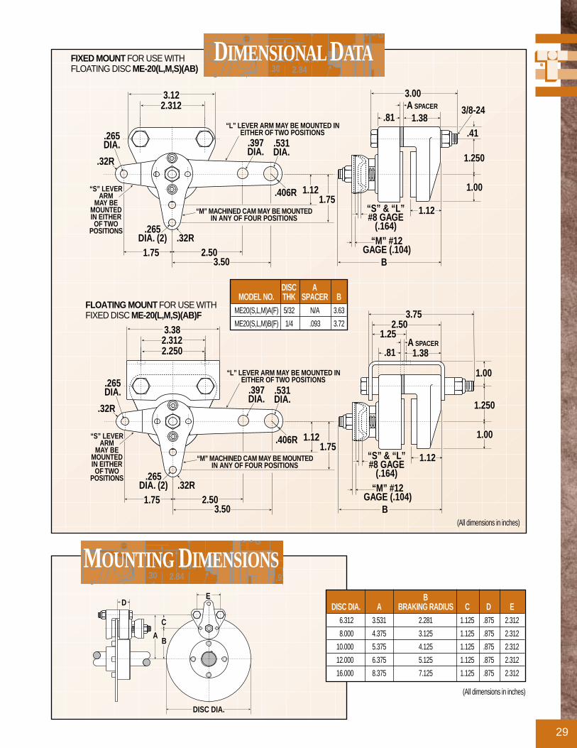
FLOATING MOUNT FOR USE WITHFIXED DISC ME-20(L,M,S)(AB)F
FIXED MOUNT FOR USE WITHFLOATING DISC ME-20(L,M,S)(AB)
(All dimensions in inches)
(All dimensions in inches)
ED
AB
C
DISC DIA.
BDISC DIA. A BRAKING RADIUS C D E
6.312 3.531 2.281 1.125 .875 2.312
8.000 4.375 3.125 1.125 .875 2.312
10.000 5.375 4.125 1.125 .875 2.312
12.000 6.375 5.125 1.125 .875 2.312
16.000 8.375 7.125 1.125 .875 2.312
DISC AMODEL NO. THK SPACER B
ME20(S,L,M)A(F) 5/32 N/A 3.63
ME20(S,L,M)B(F) 1/4 .093 3.72
ME-220 SERIESALUMINUM OR CAST IRON
30
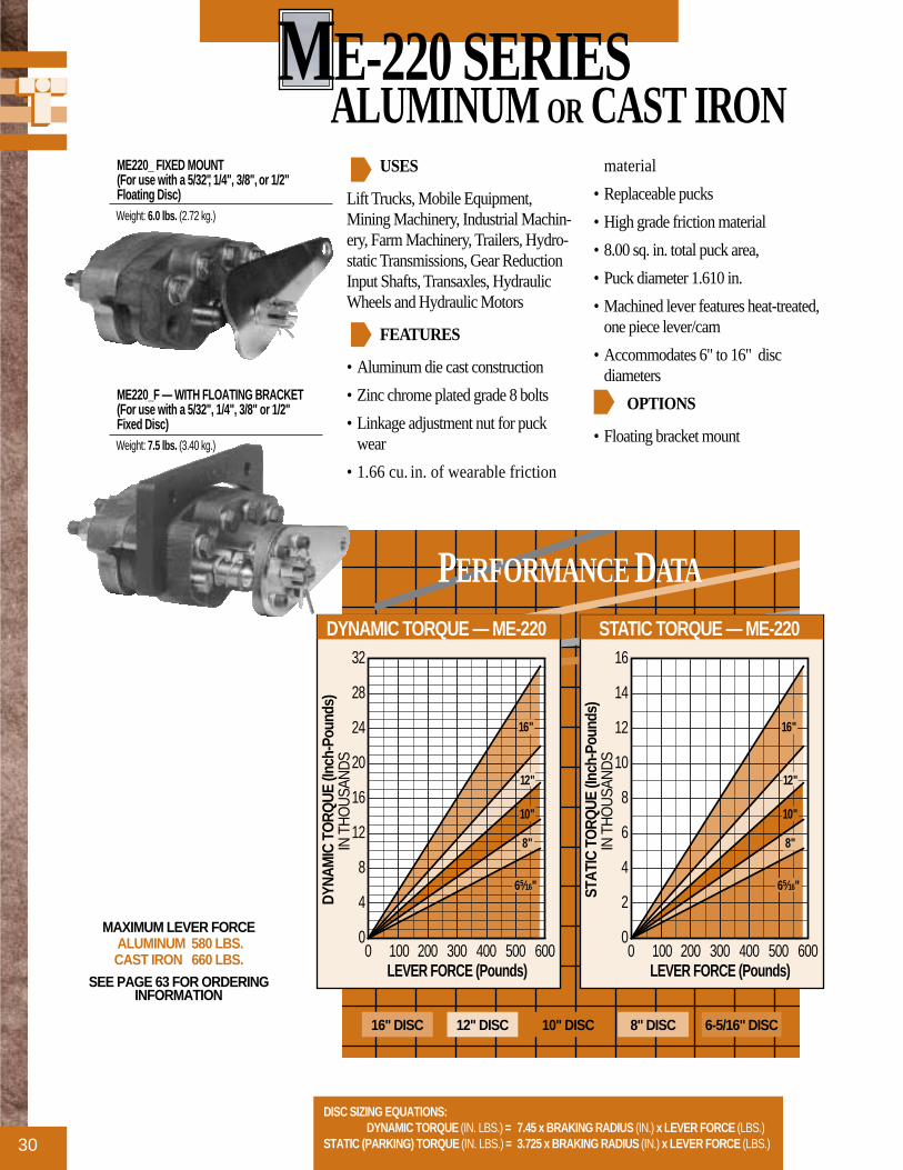
USES
Lift Trucks, Mobile Equipment,Mining Machinery, Industrial Machin-ery, Farm Machinery, Trailers, Hydro-static Transmissions, Gear ReductionInput Shafts, Transaxles, HydraulicWheels and Hydraulic Motors
FEATURES
• Aluminum die cast construction
• Zinc chrome plated grade 8 bolts
• Linkage adjustment nut for puckwear
• 1.66 cu. in. of wearable friction
material
• Replaceable pucks
• High grade friction material
• 8.00 sq. in. total puck area,
• Puck diameter 1.610 in.
• Machined lever features heat-treated,one piece lever/cam
• Accommodates 6" to 16" disc diameters
OPTIONS
• Floating bracket mount
PERFORMANCE DATA
0
2
4
6
8
10
12
14
16
0 100 200 300 400 500 600
STAT
IC T
ORQ
UE (I
nch-
Poun
ds)
IN T
HO
USA
ND
S
LEVER FORCE (Pounds)
65⁄16"
8"
10"
12"
16"
STATIC TORQUE — ME-220
0
4
8
12
16
20
24
28
32
0 100 200 300 400 500 600
DYNA
MIC
TO
RQUE
(Inc
h-Po
unds
) IN
TH
OU
SAN
DS
LEVER FORCE (Pounds)
65⁄16"
8"
10"
12"
16"
DYNAMIC TORQUE — ME-220
ME220_ FIXED MOUNT (For use with a 5/32", 1/4", 3/8", or 1/2"Floating Disc)Weight: 6.0 lbs. (2.72 kg.)
ME220_F — WITH FLOATING BRACKET(For use with a 5/32", 1/4", 3/8" or 1/2" Fixed Disc)Weight: 7.5 lbs. (3.40 kg.)
DISC SIZING EQUATIONS:DYNAMIC TORQUE (IN. LBS.) = 7.45 x BRAKING RADIUS (IN.) x LEVER FORCE (LBS.)
STATIC (PARKING) TORQUE (IN. LBS.) = 3.725 x BRAKING RADIUS (IN.) x LEVER FORCE (LBS.)
MAXIMUM LEVER FORCE ALUMINUM 580 LBS.CAST IRON 660 LBS.
SEE PAGE 63 FOR ORDERINGINFORMATION
16" DISC 12" DISC 10" DISC 8" DISC 6-5/16" DISC

31
2.1722.84.30
2.94
G
DIMENSIONAL DATA
4.7504.5001.500
.750.25
.50
.386 DIA.2-PLACES
DC
BA
1.25
7.00
2.922.84
REF 1.00
BRAKINGACTIONALTERNATIVE
POSITION OFLEVER CAM
4.004.38
1.610 DIA.PUCK
G1.61
E
1.562.00F
1.10REF.
2.1723.97
1.35REF.
1.312.937
SPACER
(All dimensions in inches)
(All dimensions in inches)CONSULT FACTORY FOR DIMENSIONAL INFORMATION ON ME220 CAST IRON
BRAKINGDISC DIA. RADIUS A B C D
6.312 2.38 2.13 3.07 3.45 4.30
8.000 3.15 3.00 3.94 4.32 5.17
10.000 4.11 4.00 4.94 5.32 6.17
12.000 5.08 5.00 5.94 6.32 7.17
16.000 7.21 7.09 8.03 8.41 9.26
DISCMODEL NO. THICKNESS E F GME-220A(F) 5/32 N/A 5.50 2.72
ME-220B(F) 1/4 .094 5.50 2.81
ME-220E(F) 1/2 .344 5.75 3.06
STOP Call 1-800-328-2174
For Assistance That Won’t Stop
Call 1-800-328-2174 For Assistance That Won’t Stop

MB3 SERIESCAST IRON
32
USES
Driveline and Wheel Mounted ParkingBrake
FEATURES
• Capable of 10,000 lbs. clamp force
• Heavy-duty cast iron housing
• Zinc chrome plated grade 5 bolts
• One step pad wear adjustment
• Designed for fixed or floatingmounts
• Machined cam allows lever posi-tioning in 60° increments
• 6.06 cu. in. of wearable frictionmaterial
• Quick-change replaceable pads
• High grade friction material
• 9.69 sq. in. total pad area,
• Hardened-steel parts provide greaterefficiency
• Accommodates 10" to 30" disc diam-eters
• Designed to be more efficient andpriced lower than competitivebrakes
PERFORMANCE DATA
0
10
20
30
40
50
60
0 100 200 300 400 500 600 700
STAT
IC T
ORQ
UE (I
nch-
Poun
ds)
IN T
HO
USA
ND
S
LEVER FORCE (Pounds)
10"
20"
25"
30"
15"
STATIC TORQUE — MB3
30" DISC 25" DISC 20" DISC25" DISC 20" DISC 15" DISC 10" DISC
MB3(For use with a 3/8" or 1/2" Disc)Weight: 13.2 lbs. (5.99 kg.)
DISC SIZING EQUATIONS:STATIC (PARKING) TORQUE (IN. LBS.) = 6.99 x BRAKING RADIUS (IN.) x LEVER FORCE (LBS.)
BRAKING RADIUS (IN.) = [DISC DIAMETER ÷ 2] - .688
MAXIMUM LEVER FORCE 660 LBS.
SEE PAGE 63 FOR ORDERINGINFORMATION

33
2.1722.84.30
2.94
G
DIMENSIONAL DATA
7.84
.25 2.934.34
.632.10.63
.50 MAX. DISCTHICKNESS
CLDISC
2.282.755.50
3.507.00
Ø.640 (4)
Ø.390 (2)
6.41
4.38
3.75
1.38
A
(All dimensions in inches)
(All dimensions in inches)BRAKINGA DISC DIA. RADIUS
5.42 10.00 4.312
7.92 15.00 6.812
10.42 20.00 9.312
12.92 25.00 11.812
15.42 30.00 14.312
STOP Call 1-800-328-2174
For Assistance That Won’t Stop
Call 1-800-328-2174 For Assistance That Won’t Stop
SHOWN WITH A 12 O’CLOCK LEVER LOCATION.ADDITIONAL LEVER LOCATIONS CAN BE POSITIONED
IN 60° INCREMENTS. CONSULT FACTORY FOR CUS-TOM LEVER POSITIONING.

FS-20 SERIESALUMINUM
34
USES
Mobile Equipment, Material HandlingEquipment, Industrial Machinery,Mining Machinery, Farm Machinery,Hydrostatic Transmissions, GearReduction Input Shafts, HydraulicWheels and Hydraulic Motors
FEATURES
• Aluminum die cast construction
• Zinc plated grade 8 bolts
• Standard Buna-N seals
• .83 cu. in. of wearable frictionmaterial
• Replaceable pucks
• High grade friction material
• 4.0 sq. in. total puck area
• Puck diameter 1.625 in.
• Steelplate floating brackets
• No maximum disc size limitation
• Fluid displacement for retraction =0.56 cu. in.
OPTIONS
• EPR seals
PERFORMANCE DATA
0
500
1000
1500
2000
2500
3000
3500
0 .063 .125 .188 .250 .313 .375
STAT
IC T
ORQ
UE (I
nch-
Poun
ds)
PUCK WEAR (Inches)
65⁄16"
8"
10"
12"
16"
STATIC TORQUE — FS20
0
100
200
300
400
500
0 .063 .125 .188 .250 .313 .375
TANG
ENTI
AL F
ORC
E (P
ound
s)
PUCK WEAR (Inches)
TANGENTIAL FORCE - FS20
DISC SIZING EQUATIONS:STATIC (PARKING) TORQUE (IN. LBS.) = TANGENTIAL FORCE (LBS.) x BRAKING RADIUS (IN.)
BRAKING RADIUS (IN.) = [DISC DIAMETER ÷ 2] - .875
MAXIMUM HYDRAULIC PRESSURE RATING 1500 PSI Non Shock
MINIMUM HYDRAULIC PRESSURE TO RELEASE BRAKE
750 PSI
SEE PAGE 63 FOR ORDERINGINFORMATION
EMERGENCY STOP WITH FLOATING BRACKET(For use with a 5/32" or 1/4"Fixed Disc)
Weight: 4.0 lbs. (1.81 kg.)
16" DISC 12" DISC 10" DISC 8" DISC 6-5/16" DISC

35
2.1722.84.30
2.94
G
DIMENSIONAL DATA
1.1562.3123.38
∅ .397THRU (2)
A
B
C
.81
1.25
.44 (2)
3.501.75
.88
3.062.66
.25 (2).22
1.211.62
.69
1.56.06
.25
E
D6.00
.62DIA.(4)
3/8-16UNC
(All dimensions in inches)
DISCMODEL NO. THICKNESS D E
FS20A .156 4.78 .500
FS20AG .156 4.78 .500
FS20B .250 4.87 .593
FS20BG .250 4.87 .593
A MAXIMUMDISC DIA. BRAKING RADIUS B C TORQUE (STATIC)
6.312 2.281 3.531 4.344 1060 in. lbs.
8.000 3.125 4.375 5.188 1453 in. lbs.
10.000 4.125 5.375 6.188 1918 in. lbs.
12.000 5.125 6.375 7.188 2383 in. lbs.
16.000 7.125 8.375 9.188 3313 in. lbs.
STOP Call 1-800-328-2174
For Assistance That Won’t Stop
Call 1-800-328-2174 For Assistance That Won’t Stop
(All dimensions in inches)

FS-220 SERIESALUMINUM
36
USES
Mobile Equipment, IndustrialMachinery, Mining Machinery, FarmMachinery, Hydrostatic Transmissions,Gear Reduction Input Shafts,Hydraulic Wheels and HydraulicMotors
FEATURES
• Aluminum die cast construction
• Zinc chrome plated grade 8 bolts
• Standard Buna-N seals
• 1.66 cu. in. of wearable frictionmaterial
• Replaceable pucks
• High grade friction material
• 8.0 sq. in. total puck area
• Puck diameter 1.610 in.
• Floating bracket
• Accommodates 6" to 16" disc diameters
OPTIONS
• EPR seals
PERFORMANCE DATA
0
1
2
3
4
5
6
7
0 .063 .125 .188 .250 .313 .375
STAT
IC T
ORQ
UE (I
nch-
Poun
ds)
(IN T
HO
USA
ND
S)
PUCK WEAR (Inches)
65⁄16"
8"
10"
12"
16"
STATIC TORQUE — FS220B
0
100
200
300
400
500
600
700
800
900
1000
0 .063 .125 .188 .250 .313 .375
TANG
ENTI
AL F
ORC
E (P
ound
s)
PUCK WEAR (Inches)
TANGENTIAL FORCE – FS220B
DISC SIZING EQUATION:STATIC (PARKING) TORQUE (IN. LBS.) = TANGENTIAL FORCE (LBS.) x BRAKING RADIUS (IN.)
MAXIMUM HYDRAULIC PRESSURE RATING 2000 PSI Non Shock
MINIMUM HYDRAULIC PRESSURE TO RELEASE BRAKE
FS220B 750 PSI FS220C 1500 PSI
SEE PAGE 63 FOR ORDERINGINFORMATION
FS220B(For use with a 5/32", 1/4", 3/8"or 1/2" Fixed Disc)
Weight: 8.0 lbs. (3.63 kg.)
FS220C(For use with a 5/32", 1/4", 3/8"or 1/2" Fixed Disc)
Weight: 11.0 lbs. (4.99 kg.)
16" DISC 12" DISC 10" DISC 8" DISC 6-5/16" DISC
37
2.1722.84.30
2.94
G
DIMENSIONAL DATA
4.7504.5001.500
.750.38
.50
.386 DIA.2-PLACES
DC
BA
1.22
7.00
2.1722.84
E
1.312.937 .30
F.38
.3751.22
EF
1.94
BLEEDERSCREW (2)
1/8 NPTFPORT
BLEEDERSCREW (2)
1/8 NPTFPORT
2.94
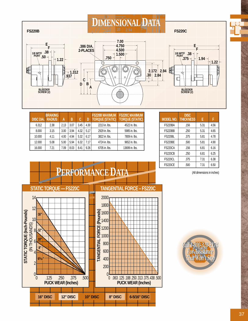
DISCMODEL NO. THICKNESS E F
FS220BA .156 5.31 4.56
FS220BB .250 5.31 4.65
FS220BL .375 5.81 4.78
FS220BE .500 5.81 4.90
FS220CA .156 6.81 6.16
FS220CB .250 6.81 6.25
FS220CL .375 7.31 6.38
FS220CE .500 7.31 6.50
BRAKING FS220B MAXIMUM FS220C MAXIMUMDISC DIA. RADIUS A B C D TORQUE (STATIC) TORQUE (STATIC)
6.312 2.38 2.13 3.07 3.45 4.30 2213 in. lbs. 4522 in. lbs.
8.000 3.15 3.00 3.94 4.32 5.17 2929 in. lbs. 5985 in. lbs.
10.000 4.11 4.00 4.94 5.32 6.17 3822 in. lbs. 7809 in. lbs.
12.000 5.08 5.00 5.94 6.32 7.17 4724 in. lbs. 9652 in. lbs.
16.000 7.21 7.09 8.03 8.41 9.26 6705 in. lbs. 13699 in. lbs.
PERFORMANCE DATA
0
2
4
6
8
10
12
14
0 .125 .250 .375 .500
STAT
IC T
ORQ
UE (I
nch-
Poun
ds)
(IN T
HO
USA
ND
S)
PUCK WEAR (Inches)
65⁄16"
8"
10"
12"
16"
STATIC TORQUE — FS220C
0
200
400
600
800
1000
1200
1400
1600
1800
2000
0 .063.125.188.250.313.375.438.500
TANG
ENTI
AL F
ORC
E (P
ound
s)
PUCK WEAR (Inches)
TANGENTIAL FORCE – FS220C
(All dimensions in inches)
FS220B FS220C
16" DISC 12" DISC 10" DISC 8" DISC 6-5/16" DISC
STOP Call 1-800-328-2174
For Assistance That Won’t Stop
Call 1-800-328-2174 For Assistance That Won’t Stop

FS-220I SERIESDUCTILE IRON
38
USES
Mobile Off-the-Road Equipment andMining Machinery
FEATURES
• Cast iron construction
• Manual retractor
• Manual wear compensator
• Zinc chrome plated grade 8 bolts
• Standard Buna-N seals
• 2.35 cu. in. of wearable frictionmaterial
• Replaceable pucks
• High grade friction material
• 9.4 sq. in. total puck area
• Puck diameter 1.610 in.
• Floating bracket
• Accommodates discs from 6" to 16"diameter
• Fluid displacement for retraction =.056 cubic inches
OPTIONS
• EPR seals
PERFORMANCE DATA
0
1
2
3
4
5
6
7
0 .125 .250 .375 .500
STAT
IC T
ORQ
UE (I
nch-
Poun
ds)
(IN T
HOUS
ANDS
)
PUCK WEAR (Inches)
65⁄16"
8"
12"
16"
10"
Unadjusted Static Torque
STATIC TORQUE — FS220BI & BI_JK
0
100
200
300
400
500
600
700
800
900
1000RELEASE PRESSURETANGENTIAL FORCE
0100
200
300
400
500
600
700
800
900
1000
0 .063.125.188.250.313.375.438.500
TAN
GEN
TIA
L FO
RC
E (P
ound
s)
REL
EASE
PR
ESSU
RE
(PSI
)
PUCK WEAR (Inches)
UNADJUSTED TAN. FORCE
UNADJUSTED RELEASE PRESS.
TANGENTIAL FORCE - FS220BI & BI_JK
DISC SIZING EQUATION:STATIC (PARKING) TORQUE (IN. LBS.) = TANGENTIAL FORCE (LBS.) x BRAKING RADIUS (IN.)
MAXIMUM HYDRAULIC PRESSURE RATING 2000 PSI Non Shock
MINIMUM HYDRAULIC PRESSURE TO RELEASE BRAKE
FS220BI 750 PSI (1000 PSI AFTER COMPENSATION)
FS220CI 1500 PSI
SEE PAGE 63 FOR ORDERINGINFORMATION
FS220B(For use with a 5/32", 1/4", 3/8"or 1/2" Fixed Disc)
Weight: 14.5 lbs. (6.58 kg.)
FS220C(For use with a 5/32", 1/4", 3/8"or 1/2" Fixed Disc)
Weight: 20.0 lbs. (9.07 kg.)
REFER TO FS220B PERFORMANCE DATA FOR CALIPERS WITHOUT “JK” OPTIONS
16" DISC 12" DISC 10" DISC 8" DISC 6-5/16" DISC

39
2.1722.84.30
2.94
G
DIMENSIONAL DATA
RECOMMENDED WEARCOMPENSATION INTERVAL
FS220BI_JK = .06" PUCK WEARFS220CI_JK = .10" PUCK WEAR
1.25
4.7504.5001.500
.750
.386 DIA.2-PLACES
CB
A
1.16
1/8-27NPTF PORT
1.68
D
7.00
.50
5.75
2.172
1.00
1.53 .31 1.25
E
F
DISCMODEL NO. THICKNESS E FFS220BIA__ .156 .500 6.32
FS220BIB__ .250 .594 6.42
FS220BIL__ .375 .718 6.54
FS220BIE__ .500 .844 6.67
FS220BIA__ .156 .562 7.96
FS220BIB__ .250 .6.56 8.06
FS220BIL__ .375 .780 8.18
FS220BIE__ .500 .906 8.32
BRAKING FS220BI MAXIMUM FS220CI MAXIMUMDISC DIA. RADIUS A B C D TORQUE (STATIC) TORQUE (STATIC)
6.312 2.38 2.13 3.07 3.45 4.30 2213 in. lbs. 4522 in. lbs.
8.000 3.15 3.00 3.94 4.32 5.17 2929 in. lbs. 5985 in. lbs.
10.000 4.11 4.00 4.94 5.32 6.17 3822 in. lbs. 7809 in. lbs.
12.000 5.08 5.00 5.94 6.32 7.17 4724 in. lbs. 9652 in. lbs.
16.000 7.21 7.09 8.03 8.41 9.26 6705 in. lbs. 13699 in. lbs.
PERFORMANCE DATA
0
2
4
6
8
10
12
14
0 .10 .20 .30 .40 .50
STA
TIC
TO
RQ
UE
(Inch
-Pou
nds)
(IN
TH
OU
SAN
DS)
PUCK WEAR (Inches)
65⁄16"
16"
Unadjusted Static Torque
8"
10"
12"
STATIC TORQUE — FS220CI & CI_JK
0
200
400
600
800
1000
1200
1400
1600
1800
2000RELEASE PRESSURETANGENTIAL FORCE
0200
400
600
800
1000
1200
1400
1600
1800
2000
0 .05.10.15.20.25 .30.35.40.45.50
TAN
GEN
TIA
L FO
RC
E (P
ound
s)
REL
EASE
PR
ESSU
RE
(PSI
)
PUCK WEAR (Inches)
UNADJUSTED TAN. FORCE
UNADJUSTED RELEASE PRESS.
TANGENTIAL FORCE — FS220CI & CI_JK
(All dimensions in inches)
FS220BI FS220CI
REFER TO FS220C PERFORMANCE DATA FOR CALIPERS WITHOUT “JK” OPTIONS
1.251.16
1/8-27NPTF PORT
.50
2
1.53 .31 1.25
E
F
16" DISC 12" DISC 10" DISC 8" DISC 6-5/16" DISC
STOP Call 1-800-328-2174
For Assistance That Won’t Stop
Call 1-800-328-2174 For Assistance That Won’t Stop

FS-440 SERIESDUCTILE IRON
40
USES
Mobile Equipment, Material HandlingEquipment, Industrial Machinery,Mining Machinery, Farm Machinery,Hydrostatic Transmissions, GearReduction Input Shafts, HydraulicWheels and Hydraulic Motors
FEATURES
• Cast ductile iron construction
• Cadmium plated grade 8 bolts
• Standard Buna-N seals
• .83 cu. in. of wearable frictionmaterial
• Replaceable pucks
• High grade friction material
• 4.0 sq. in. total puck area
• Puck diameter 1.610 in.
• Accommodates 10" to 24" disc diameters
• Fluid displacement for retraction =0.56 cu. in.
OPTIONS
• EPR seals
PERFORMANCE DATA
0
4
8
12
16
20
24
0 .125 .250 .375 .500 .625 .750.813
STA
TIC
TO
RQ
UE
(Inch
-Pou
nds)
(IN
TH
OU
SAN
DS)
PUCK WEAR (Inches)
Unadjusted Static Torque
10"
12"
16"
20"
24"
STATIC TORQUE — FS440
0200400600800
10001200140016001800200022002400
RELEASE PRESSURETANGENTIAL FORCE
0200400600800100012001400
0 .12 .25 .38 .50 .63 .75.81
TAN
GEN
TIA
L FO
RC
E (P
ound
s)
REL
EASE
PR
ESSU
RE
(PSI
)
PUCK WEAR (Inches)
UNADJUSTED TAN. FORCE
UNADJUSTED RELEASE PRESS.
TANGENTIAL FORCE - FS440
DISC SIZING EQUATIONS:STATIC (PARKING) TORQUE (IN. LBS.) = TANGENTIAL FORCE (LBS.) x BRAKING RADIUS (IN.)
BRAKING RADIUS (IN.) = [DISC DIAMETER ÷ 2] - 1.310
MAXIMUM HYDRAULIC PRESSURE RATING 2000 PSI Non Shock
MINIMUM HYDRAULIC PRESSURE TO RELEASE BRAKE
1310 PSI
SEE PAGE 63 FOR ORDERINGINFORMATION
EMERGENCY STOP WITH FLOATING BRACKET(For use with a 3/8", 1/2", 1", 1-1/4" or 1-1/2" Fixed Disc)
Weight: 27.0 lbs. (12.25 kg.)
NOTE: Available Tol-O-Matic Disc Sizes 65⁄16", 8", 10", 12", and 16"
16" DISC 12" DISC 10" DISC24" DISC 20" DISC24" DISC 20" DISC

41
2.1722.84.30
2.94
G
DIMENSIONAL DATA
1.43R 1.56R
2.3124.6255.88
1.625
4.20R14° 14°
1.249(2)1/4-18
NPT PORT
.75R
.38
.88
F4.79
H
G
AB
.7241.035
C
OPTIONALSPACER
.88
D E
4.00DIA.
.515 DIA. (2)MOUNTING
HOLES
(All dimensions in inches)
DISCMODEL NO. THICKNESS C D E F G H
FS-440L .375 1.75 .83 .52 .12 .56 6.91
FS-440E .500 1.75 .77 .46 .06 .62 6.91
FS-440N 1.000 2.25 .77 .46 .06 1.12 7.41
FS-440O 1.250 2.50 .77 .46 .06 1.38 7.66
FS-440Q 1.500 2.75 .77 .46 .06 1.62 7.91
B MAXIMUMDISC DIA. A BRAKING RADIUS TORQUE (STATIC)
10.000 5.315 3.690 8,118 in. lbs.
12.000 6.315 4.690 10,318 in. lbs.
16.000 8.315 6.690 14,718 in. lbs.
20.000 10.315 8.690 19,118 in. lbs.
24.000 12.315 10.690 23,518 in. lbs.
STOP Call 1-800-328-2174
For Assistance That Won’t Stop
Call 1-800-328-2174 For Assistance That Won’t Stop
(All dimensions in inches)
RECOMMENDED WEARCOMPENSATION INTERVAL FS440 = .12" PUCK WEAR

FS-595 SERIESDUCTILE IRON
42
USES
Mobile Off-the-Road Equipment,Industrial Machinery and MiningMachinery
FEATURES
• Cast ductile iron housings
• Grade 8 bolts Cadmium plated
• Standard Buna-N seals
• .812 cu. in. of wearable frictionmaterial
• Replaceable pucks
• High grade friction material
• 9.14 sq. in. total puck area per brake
• Puck diameter 2.50 in.
• No maximum disc size limitation
• Fluid displacement for .030 clearanceFS595 = .230 cu. in.FS595HD = .460 cu. in
OPTIONS
• EPR seals
• Adaptable to thinner discs, consultfactory.
PERFORMANCE DATA
0
5
10
15
20
25
30
35
0 .125 .250 .375 .500 .625 .750
STA
TIC
TO
RQ
UE
(Inc
h-P
ound
s)
(IN T
HO
US
AN
DS
)
PUCK WEAR (Inches)
16"
14"
Unadjusted Static Torque
STATIC TORQUE — FS595
0
500
1000
1500
2000
2500
3000
3500
4000
4500
RELEASE PRESSURETANGENTIAL FORCE
0500
1000
1500
0 .12 .25 .38 .50 .63 .75
TAN
GE
NTI
AL
FOR
CE
(Pou
nds)
RE
LEA
SE
PR
ES
SU
RE
(PS
I)
PUCK WEAR (Inches)
UNADJUSTED TAN. FORCE
UNADJUSTED RELEASE PRESS.
TANGENTIAL FORCE - FS595
DISC SIZING EQUATIONS:STATIC (PARKING) TORQUE (IN. LBS.) = TANGENTIAL FORCE (LBS.) x BRAKING RADIUS (IN.)
BRAKING RADIUS (IN.) = [DISC DIAMETER ÷ 2] - 1.280
MAXIMUM HYDRAULIC PRESSURE RATING 2000 PSI Non Shock
MINIMUM HYDRAULIC PRESSURE TO RELEASE BRAKE
1400 PSI
SEE PAGE 63 FOR ORDERINGINFORMATION
FS595(For use with a 1/2", 1", 1-1/4" or 1-1/2" Fixed Disc)
Weight: 36.0 lbs. (16.33 kg.)
FS595 DUAL(For use with a 1/2", 1", 1-1/4" or 1-1/2" Fixed Disc)
Weight: 72.0 lbs. (32.66 kg.)
16" DISC 14" DISC
NOTE: Available Tol-O-Matic Disc Sizes 65⁄16", 8", 10", 12", and 16"

43
2.1722.84.30
2.94
G
DIMENSIONAL DATA
3.437
.781DIA. (2)
2.437
7.44
4.88DIA. (2)
3.632.312
3.2505.75
3/4 x 3/4 SQ. FORMANUAL ADJUSTMENT
BLEEDERVALVE (2)
A
3.12CLEARANCE
RAD. W/ 14" DIA.+ LARGER
B
3.437
2.437
7.44
4.88DIA. (4)
3.4376.875
3/4 x 3/4 SQ. FORMANUAL ADJUSTMENT
BLEEDERVALVE (2)
1.753.81
7.63
1.69
3.38
2.00(4)
1.500THK.DISC(REF)
1/8-27 NPTFINLET (2)
A
3.12CLEARANCE
RAD. W/ 14" DIA.+ LARGER
B
1.48
2.437
9.88
(All dimensions in inches)
PERFORMANCE DATA
0
10
20
30
40
50
60
0 .125 .250 .375 .500 .625 .750
STA
TIC
TO
RQ
UE
(Inc
h-P
ound
s)
(IN T
HO
US
AN
DS
)
PUCK WEAR (Inches)
16"
14"
Unadjusted Static Torque
STATIC TORQUE – FS595DUAL
0
1000
2000
3000
4000
5000
6000
7000
8000
9000
RELEASE PRESSURETANGENTIAL FORCE
0500
1000
1500
0 .12 .25 .38 .50 .63 .75
TAN
GE
NTI
AL
FOR
CE
(Pou
nds)
RE
LEA
SE
PR
ES
SU
RE
(PS
I)
PUCK WEAR (Inches)
UNADJUSTED TAN. FORCE
UNADJUSTED RELEASE PRESS.
TANGENTIAL FORCE - FS595DUAL
RECOMMENDED WEARCOMPENSATION INTERVAL FS595 = .25" PUCK WEAR
MAXIMUM TOTAL WEAR FS595 = .75" PUCK WEAR
(All dimensions in inches)
B FS595 MAXIMUM FS595DUAL MAXIMUMDISC DIA. A BRAKING RADIUS TORQUE (STATIC) TORQUE (STATIC)
14.000 8.58 5.72 26,426 in. lbs. 52,852 in. lbs.
16.000 9.67 6.72 31,046 in. lbs. 62,092 in. lbs.
NOTE: Available Tol-O-Matic Disc Sizes 65⁄16", 8", 10", 12", and 16"
16" DISC 14" DISC
STOP Call 1-800-328-2174
For Assistance That Won’t Stop
Call 1-800-328-2174 For Assistance That Won’t Stop

FIXED HUB AND DISC ASSEMBLIES
44
FEATURES
• Carbon 1010 steel discs, flat within.010 inch, stress relieved and blan-chard ground to an 80 (RMS) micro-inch finish
• Hubs machined from cold rolled steel
• Socket head cap screw fasteners
• Key way set screws
(All dimensions in inches)
(All dimensions in inches)
ASSEMBLY NO. BORE SIZE KEY SIZE0801-0008 .500 .125 x .125
0801-0010 .625 .188 x .188
0801-0012 .750 .188 x .188
0801-0014 .875 .188 x .188
0801-0016 1.000 .250 x .250
ASSEMBLY NO. BORE SIZE KEY SIZE0802-0016 1.000 .250 x .250
0802-0018 1.125 .250 x .250
0802-0020 1.250 .250 x .250
0802-0022 1.375 .313 x .313
0802-0024 1.500 .375 x .375
0802-0026 1.625 .375 x .375
0802-0028 1.750 .375 x .375
DISC SIZE: 6-5/16"
DISC SIZE: 8"(All dimensions in inches)
ASSEMBLY NO. BORE SIZE KEY SIZE0803-0016 1.000 .250 x .250
0803-0018 1.125 .250 x .250
0803-0020 1.250 .250 x .250
0803-0022 1.375 .313 x .313
0803-0024 1.500 .375 x .375
0803-0026 1.625 .375 x .375
0803-0028 1.750 .375 x .375
DISC SIZE: 10"
(All dimensions in inches)
ASSEMBLY NO. BORE SIZE KEY SIZE0804-0024 1.500 .375 x .375
0804-0028 1.750 .375 x .375
0804-0032 2.000 .500 x .500
0804-0036 2.250 .500 x .500
0804-0040 2.500 .625 x .625
DISC SIZE: 12"
(All dimensions in inches)
ASSEMBLY NO. BORE SIZE KEY SIZE0805-0024 1.500 .375 x .375
0805-0028 1.750 .375 x .375
0805-0032 2.000 .500 x .500
0805-0036 2.250 .500 x .500
0805-0040 2.500 .625 x .625
DISC SIZE: 16"
PERFORMANCE DATA
DISC TORQUEDIAMETER RATING
6.313 3,000 in. lbs.
8.000 12,000 in. lbs.
10.000 12,000 in. lbs.
12.000 36,000 in. lbs.
16.000 36,000 in. lbs.
MAXIMUM TORQUE RATINGS
ALSO SEE PAGE 59 FORMAXIMUM BTU/HR.
(All dimensions in inches)
DISC DISCDIAMETER THICKNESS BTUs JOULES
6.313 .156 43.55 45,942
8.000 .156 73.93 77,986
10.000 .156 120.05 126,625
12.000 .156 164.71 173,730
16.000 .250 494.12 521,191
SINGLE STOP MAXIMUM ENERGYABSORPTION CAPACITIES*
*Disc Temperature 380° (All dimensions in inches)
HUB & DISC ASSEMBLY(For use with Pneumatic, Hydraulic, Mechanical or Spring Applied Caliper Disc Brakes)6.313 Diameter Disc Weight: 1.37 lbs. (.62 kg.)8.000 Diameter Disc Weight: 3.52 lbs. (1.60 kg.)
10.000 Diameter Disc Weight: 5.46 lbs. (2.48 kg.)12.000 Diameter Disc Weight: 7.91 lbs. (3.59 kg.)16.000 Diameter Disc Weight: 14.06 lbs. (3.38 kg.)

2.1722.84.30
2.94
G
DIMENSIONAL DATA
45
2.250DIA.
.1561.250
.38
SET SCREW (2)#10-32 UNC. 90°
APART
6.312DIA.
BORE
3.625DIA.
.1561.078
.875
8.000DIA.
BORE
2.250
2.355DIA.
3.625DIA.
.1561.078
.875
10.000DIA.
BORE
2.250
2.355DIA.
3.625DIA.
.1562.000
12.000DIA.
BORE
3.750
5.250DIA.
3.625DIA.
.2502.000
16.000DIA.
BORE
3.750
5.250DIA.
DISC SIZE 6-5/16"
DISC SIZE 8" DISC SIZE 12"
DISC SIZE 10"
DISC SIZE 16"

FIXED HUB AND DISC ASSEMBLIES WITH Q.D.BUSHINGS
46
FEATURES
• Carbon 1010 steel discs, flat within.010 inch, stress relieved and blan-chard ground to an 80 (RMS) micro-inch finish
• Socket head cap screw fasteners
• Key way set screws
• Upper lock quick disconnect bushings
ASSEMBLY NO. BORE SIZE KEY SIZE0801-0109 .563 .125 x .1250801-0110 .625 .125 x .1250801-0111 .688 .188 x .188 0801-0112 .750 .188 x .1880801-0113 .813 .188 x .188 0801-0114 .875 .188 x .1880801-0115 .938 .250 x .2500801-0116 1.000 .250 x .2500801-0117 1.063 .250 x .250
ASSEMBLY NO. BORE SIZE KEY SIZE0802-0108 .500 .125 x .1250802-0109 .563 .125 x .1250802-0110 .625 .188 x .1880802-0111 .688 .188 x .1880802-0112 .750 .188 x .1880802-0113 .813 .188 x .1880802-0114 .875 .188 x .1880802-0115 .938 .250 x .2500802-0116 1.000 .250 x .2500802-0117 1.063 .250 x .2500802-0118 1.125 .250 x .2500802-0119 1.188 .250 x .2500802-0120 1.250 .250 x .2500802-0121 1.313 .313 x .3130802-0122 1.375 .313 x .3130802-0123 1.438 .375 x .250*0802-0124 1.500 .375 x .250*0802-0125 1.563 .375 x .250*
DISC SIZE: 6-5/16"
DISC SIZE: 8"
(All dimensions in inches)
DISC SIZE: 10"
ASSEMBLY NO. BORE SIZE KEY SIZE0804-0108 .500 .125 x .1250804-0109 .563 .125 x .1250804-0110 .625 .188 x .1880804-0111 .688 .188 x .1880804-0112 .750 .188 x .1880804-0113 .813 .188 x .1880804-0114 .875 .188 x .1880804-0115 .938 .250 x .2500804-0116 1.000 .250 x .2500804-0117 1.063 .250 x .2500804-0118 1.125 .250 x .2500804-0119 1.188 .250 x .2500804-0120 1.250 .250 x .2500804-0121 1.313 .313 x .3130804-0122 1.375 .313 x .3130804-0123 1.438 .375 x .3750804-0124 1.500 .375 x .3750804-0125 1.563 .375 x .3750804-0126 1.625 .375 x .3750804-0127 1.688 .375 x .3750804-0128 1.750 .375 x .3750804-0129 1.813 .375 x .3750804-0130 1.875 .500 x .5000804-0131 1.938 .500 x .5000804-0132 2.000 .500 x .5000804-0133 2.063 .500 x .5000804-0134 2.125 .500 x .5000804-0135 2.188 .500 x .5000804-0136 2.250 .500 x .5000804-0137 2.313 .500 x .625*0804-0138 2.375 .500 x .625*0804-0139 2.438 .500 x .625*0804-0140 2.500 .500 x .625*0804-0141 2.563 .375 x .625*0804-0142 2.625 .375 x .625*0804-0143 2.688 .375 x .625*0804-0144 2.750 .375 x .625*
DISC SIZE: 12"
ASSEMBLY NO. BORE SIZE KEY SIZE0805-0108 .500 .125 x .1250805-0109 .563 .125 x .1250805-0110 .625 .188 x .1880805-0111 .688 .188 x .1880805-0112 .750 .188 x .1880805-0113 .813 .188 x .1880805-0114 .875 .188 x .1880805-0115 .938 .250 x .2500805-0116 1.000 .250 x .2500805-0117 1.063 .250 x .2500805-0118 1.125 .250 x .2500805-0119 1.188 .250 x .2500805-0120 1.250 .250 x .2500805-0121 1.313 .313 x .3130805-0122 1.375 .313 x .3130805-0123 1.438 .375 x .3750805-0124 1.500 .375 x .3750805-0125 1.563 .375 x .3750805-0126 1.625 .375 x .3750805-0127 1.688 .375 x .3750805-0128 1.750 .375 x .3750805-0129 1.813 .375 x .3750805-0130 1.875 .500 x .5000805-0131 1.938 .500 x .5000805-0132 2.000 .500 x .5000805-0133 2.063 .500 x .5000805-0134 2.125 .500 x .5000805-0135 2.188 .500 x .5000805-0136 2.250 .500 x .5000805-0137 2.313 .500 x .625*0805-0138 2.375 .500 x .625*0805-0139 2.438 .500 x .625*0805-0140 2.500 .500 x .625*0805-0141 2.563 .375 x .625*0805-0142 2.625 .375 x .625*0805-0143 2.688 .375 x .625*0805-0144 2.750 .375 x .625*
DISC SIZE: 16"
ASSEMBLY NO. BORE SIZE KEY SIZE0803-0108 .500 .125 x .1250803-0109 .563 .125 x .1250803-0110 .625 .188 x .1880803-0111 .688 .188 x .1880803-0112 .750 .188 x .1880803-0113 .813 .188 x .1880803-0114 .875 .188 x .1880803-0115 .938 .250 x .2500803-0116 1.000 .250 x .2500803-0117 1.063 .250 x .2500803-0118 1.125 .250 x .2500803-0119 1.188 .250 x .2500803-0120 1.250 .250 x .2500803-0121 1.313 .313 x .3130803-0122 1.375 .313 x .3130803-0123 1.438 .375 x .250*0803-0124 1.500 .375 x .250*0803-0125 1.563 .375 x .250*
*Non-standard keys are supplied along with hub and disc assemblies
HUB & DISC ASSEMBLY WITH Q.D. BUSHINGS(For use with Pneumatic, Hydraulic, Mechanical or Spring Applied Caliper Disc Brakes)
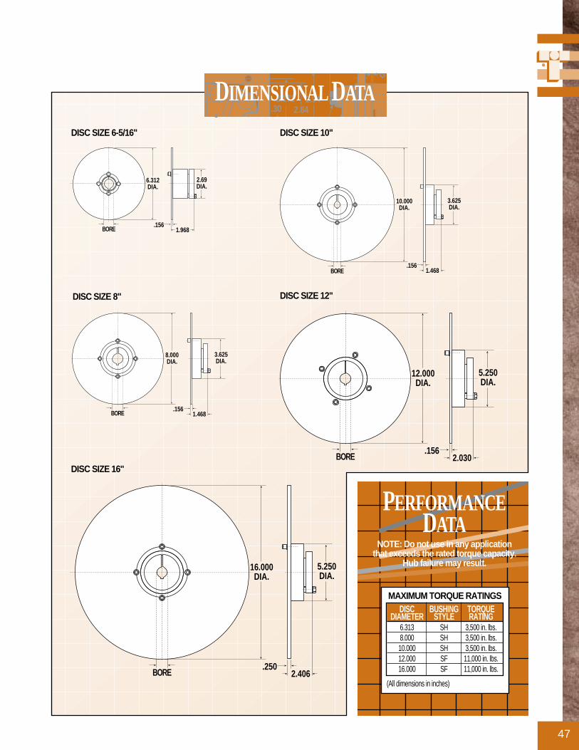
47
2.1722.84.30
2.94
G
DIMENSIONAL DATA
2.69DIA.
.1561.968
6.312DIA.
BORE
3.625DIA.
.1561.468
8.000DIA.
BORE
3.625DIA.
.1561.468
10.000DIA.
BORE
5.250DIA.
.1562.030
12.000DIA.
BORE
5.250DIA.
.2502.406
16.000DIA.
BORE
DISC SIZE 6-5/16"
DISC SIZE 8" DISC SIZE 12"
DISC SIZE 10"
DISC SIZE 16"
PERFORMANCEDATA
NOTE: Do not use in any application that exceeds the rated torque capacity.
Hub failure may result.
DISC BUSHING TORQUEDIAMETER STYLE RATING
6.313 SH 3,500 in. lbs.8.000 SH 3,500 in. lbs.10.000 SH 3,500 in. lbs.12.000 SF 11,000 in. lbs.16.000 SF 11,000 in. lbs.
MAXIMUM TORQUE RATINGS
(All dimensions in inches)

Q.D. BUSHINGS AND HUBS
48
Q.D. BUSHINGS(MUST BE USDED WITH Q.D. HUBS ON NEXT PAGE)
2.1722.84.30
2.94
G
DIMENSIONAL DATA
(All dimensions in inches)
(Dimensions in inches)
ASSY. NO. TYPE FITS DISC SIZES BORE KEY SIZE WT. (LBS.)0801-1122 SH 8.000 & 10.000 .500 .125 x .125 0.90801-1123 SH 6.313 & 8.000 & 10.000 .563 .125 x .125 0.90801-1124 SH 8.000 & 10.000 .625 .188 x .188 0.90801-1125 SH 6.313 & 8.000 & 10.000 .688 .188 x .188 0.80801-1126 SH 6.313 & 8.000 & 10.000 .750 .188 x .188 0.80801-1127 SH 6.313 & 8.000 & 10.000 .813 .188 x .188 0.80801-1128 SH 6.313 & 8.000 & 10.000 .875 .188 x .188 0.80801-1129 SH 6.313 & 8.000 & 10.000 .938 .250 x .250 0.80801-1131 SH 6.313 & 8.000 & 10.000 1.000 .250 x .250 0.70801-1132 SH 6.313 & 8.000 & 10.000 1.063 .250 x .250 0.70801-1133 SH 6.313 & 8.000 & 10.000 1.125 .250 x .250 0.70801-1134 SH 8.000 & 10.000 1.188 .250 x .250 0.60801-1135 SH 8.000 & 10.000 1.250 .250 x .250 0.60801-1136 SH 8.000 & 10.000 1.313 .313 x .313 0.50801-1137 SH 8.000 & 10.000 1.375 .313 x .313 0.50801-1138 SH 8.000 & 10.000 1.438 .375 x .250* 0.50801-1139 SH 8.000 & 10.000 1.500 .375 x .250* 0.40801-1140 SH 8.000 & 10.000 1.563 .375 x .250* 0.40801-1141 SH 8.000 & 10.000 1.625 .375 x .250* 0.40801-1142 SF 12.000 & 16.000 .500 .125 x .125 4.90801-1143 SF 12.000 & 16.000 .563 .125 x .125 4.90801-1144 SF 12.000 & 16.000 .625 .188 x .188 4.80801-1145 SF 12.000 & 16.000 .688 .188 x .188 4.80801-1146 SF 12.000 & 16.000 .750 .188 x .188 4.80801-1147 SF 12.000 & 16.000 .813 .188 x .188 4.70801-1148 SF 12.000 & 16.000 .875 .188 x .188 4.70801-1149 SF 12.000 & 16.000 .938 .250 x .250 4.60801-1150 SF 12.000 & 16.000 1.000 .250 x .250 4.60801-1151 SF 12.000 & 16.000 1.063 .250 x .250 4.5
Q.D. BUSHINGS
ASSY. NO. TYPE FITS DISC SIZES BORE KEY SIZE WT. (LBS.)
2.69
.88.38
1.871DIA.
1.25
.12.75 IN./FT.
TAPER
KEY SEAT 1/2 – 1-3/8 BORE: STD.1-7/16 – 1-5/8 BORE: 3/8 x 1/16
1/4-20, 3 HOLESEQ. SPACED ON2-1/4 DIA. B.C.
4.63
1.50.50
3.125
2.00
.12.75 IN./FT.
TAPER
KEY SEAT 1/2 – 2-1/4 BORE: STD.2-5/16 – 2-1/2 BORE: 5/8 x 3/162-9/16 – 2-3/4 BORE: 5/8 x 1/16
3/8-16, 3 HOLESEQ. SPACED ON3-7/8 DIA. B.C.
0801-1152 SF 12.000 & 16.000 1.125 .250 x .250 4.50801-1153 SF 12.000 & 16.000 1.188 .250 x .250 4.40801-1154 SF 12.000 & 16.000 1.250 .250 x .250 4.40801-1155 SF 12.000 & 16.000 1.313 .313 x .313 4.30801-1156 SF 12.000 & 16.000 1.375 .313 x .313 4.20801-1157 SF 12.000 & 16.000 1.438 .375 x .375 4.10801-1158 SF 12.000 & 16.000 1.500 .375 x .375 4.00801-1159 SF 12.000 & 16.000 1.563 .375 x .375 4.00801-1160 SF 12.000 & 16.000 1.625 .375 x .375 3.90801-1161 SF 12.000 & 16.000 1.688 .375 x .375 3.80801-1162 SF 12.000 & 16.000 1.750 .375 x .375 3.70801-1163 SF 12.000 & 16.000 1.875 .500 x .500 3.50801-1164 SF 12.000 & 16.000 1.938 .500 x .500 3.40801-1165 SF 12.000 & 16.000 2.000 500 x .500 3.30801-1166 SF 12.000 & 16.000 2.063 .500 x .500 3.20801-1167 SF 12.000 & 16.000 2.125 .500 x .500 3.10801-1168 SF 12.000 & 16.000 2.188 .500 x .500 3.00801-1169 SF 12.000 & 16.000 2.250 .500 x .500 2.90801-1170 SF 12.000 & 16.000 2.313 .500 x .625* 2.90801-1171 SF 12.000 & 16.000 2.375 .500 x .625* 2.80801-1172 SF 12.000 & 16.000 2.438 .500 x .625* 2.70801-1173 SF 12.000 & 16.000 2.500 .500 x .625* 2.60801-1174 SF 12.000 & 16.000 2.563 .375 x .625* 2.40801-1175 SF 12.000 & 16.000 2.625 .375 x .625* 2.30801-1176 SF 12.000 & 16.000 2.688 .375 x .625* 2.20801-1177 SF 12.000 & 16.000 2.750 .375 x .625* 2.00801-1178 SF 12.000 & 16.000 2.812 NONE 1.80801-1179 SF 12.000 & 16.000 2.937 NONE 1.5
FOR 6.313", 8.000" & 10.000"DIAMETER DISCS(SH STANDARD)
FOR 10.000" THRU 16.000"DIAMETER DISCS(SF STANDARD)
*Non-standard keys are supplied along with hub and disc assemblies
BUSHING INSTALLATION TORQUEWhen a wrench or length of pipe is used toincrease leverage in tightening bushingscrews, it is imperative to adhere to thewrench torque values given below.
When mounting the bushing, the tighteningforce on the screws is multiplied many times bythe wedging action of the tapered surface. Thisaction compresses the bushing for a snug fit onthe shaft. The bushing screws should always betightened alternately and progressively.
WRENCH WRENCH WRENCHBUSHING TORQUE LENGTH PULL
(IN.-LBS.) (INCHES) (POUNDS)SH 108 4 27
SF 360 6 60
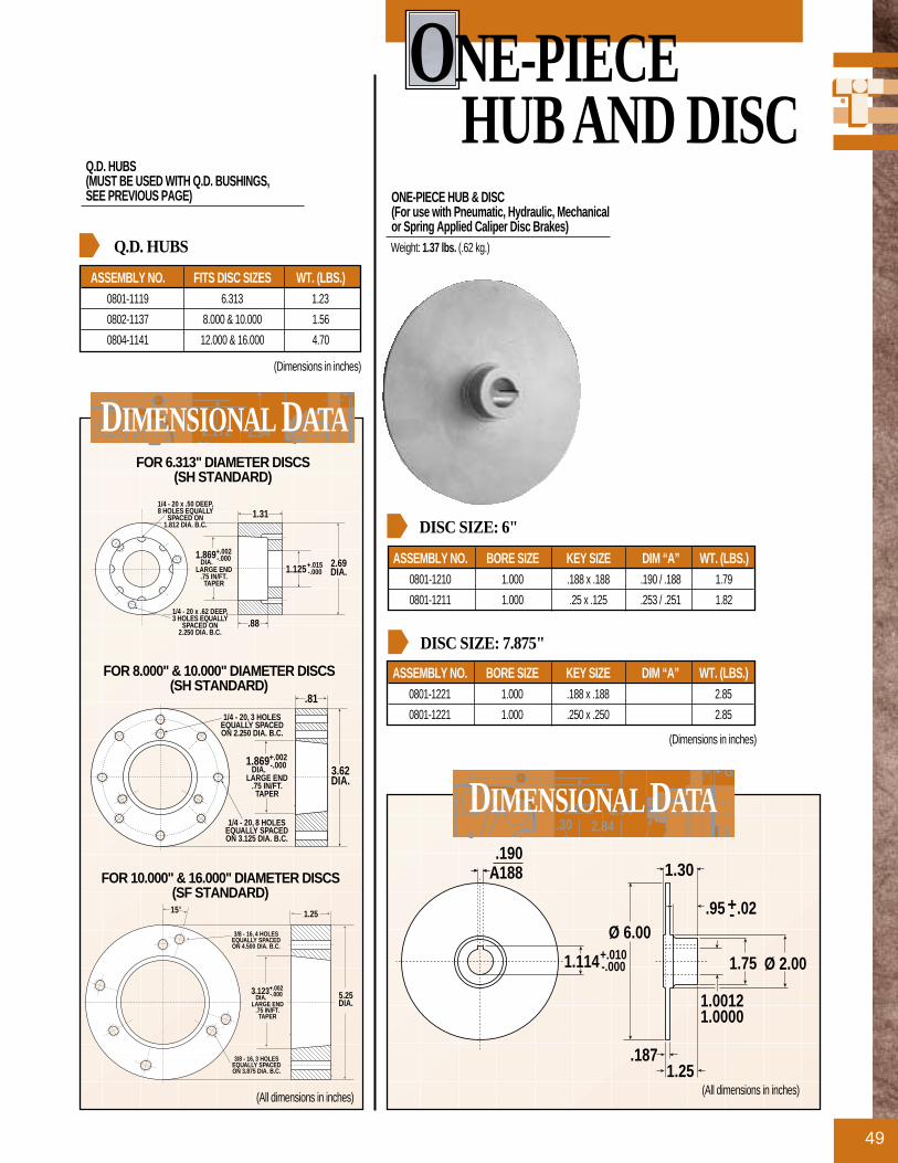
ONE-PIECE HUB AND DISC
49
ONE-PIECE HUB & DISC(For use with Pneumatic, Hydraulic, Mechanical or Spring Applied Caliper Disc Brakes)Weight: 1.37 lbs. (.62 kg.)
Q.D. HUBS(MUST BE USED WITH Q.D. BUSHINGS, SEE PREVIOUS PAGE)
2.1722.84.30
2.94
G
DIMENSIONAL DATA
2.1722 8430
2.94DIMENSIONAL DATA
(Dimensions in inches)
ASSEMBLY NO. BORE SIZE KEY SIZE DIM “A” WT. (LBS.)0801-1210 1.000 .188 x .188 .190 / .188 1.79
0801-1211 1.000 .25 x .125 .253 / .251 1.82
DISC SIZE: 6"
ASSEMBLY NO. BORE SIZE KEY SIZE DIM “A” WT. (LBS.)0801-1221 1.000 .188 x .188 2.85
0801-1221 1.000 .250 x .250 2.85
DISC SIZE: 7.875"
(Dimensions in inches)
ASSEMBLY NO. FITS DISC SIZES WT. (LBS.)0801-1119 6.313 1.23
0802-1137 8.000 & 10.000 1.56
0804-1141 12.000 & 16.000 4.70
Q.D. HUBS
(All dimensions in inches) (All dimensions in inches)
+.010-.0001.114
A 1.30
Ø 2.001.75
.95 .02
1.00121.0000
Ø 6.00
+-
1.25.187
.190
.188
1/4 - 20 x .50 DEEP,8 HOLES EQUALLY
SPACED ON1.812 DIA. B.C.
2.69DIA.
1.869 DIA.
+.002-.000
LARGE END.75 IN/FT.TAPER
+.015-.0001.125
1.31
.881/4 - 20 x .62 DEEP,3 HOLES EQUALLY
SPACED ON2.250 DIA. B.C.
1/4 - 20, 8 HOLESEQUALLY SPACEDON 3.125 DIA. B.C.
3.62DIA.
1.869 DIA.
+.002-.000
LARGE END.75 IN/FT.TAPER
.81
1/4 - 20, 3 HOLESEQUALLY SPACEDON 2.250 DIA. B.C.
3/8 - 16, 4 HOLESEQUALLY SPACEDON 4.500 DIA. B.C.
5.25DIA.
3.123 DIA.
+.002-.000
LARGE END.75 IN/FT.TAPER
1.25
3/8 - 16, 3 HOLESEQUALLY SPACEDON 3.875 DIA. B.C.
15°
FOR 6.313" DIAMETER DISCS(SH STANDARD)
FOR 8.000" & 10.000" DIAMETER DISCS(SH STANDARD)
FOR 10.000" & 16.000" DIAMETER DISCS(SF STANDARD)

OPTIONAL DISCS
50
(All dimensions in inches)
ASSEMBLY DISC DISCNUMBER DIAMETER THICKNESS0801-1200 6.313 .156
0802-1200 8.000 .156
0803-1200 10.000 .156
0804-1200 12.000 .156
0805-1200 16.000 .250
BLANK DISCS
(All dimensions in inches)
ASSEMBLY DISC DISC B.C. NO. OF HOLE PILOT CLEAR.NUMBER DIA. “D” THK “t” DIAMETER BOLT HOLES DIA. “d” DIAMETER “A”0801-1206 6.313 .156 1.812 8 .332 1.376
0802-1208 8.000 .156 3.125 8 .343 2.375
0803-1210 10.000 .156 3.125 8 .343 2.375
0804-1212 12.000 .156 4.500 4 .406 3.750
0805-1216 16.000 .250 4.500 4 .406 3.750
0805-1220 16.000 .500 4.500 4 .406 3.750
DISCS WITH BOLT CIRCLES AND PILOT HOLE
2.1722.84.30
2.94
G
DIMENSIONAL DATA
“d” DIA.(n HOLES)
EQ. SPACEDON B.C. DIA.
B.C.DIA.
DISCDIA.“D”
PILOTCLEARANCE
DIA. “A”
DISC DIA. “t”
PLEASE CONSULT THE FACTORY FOR YOURSPECIAL DISC REQUEST
BLANK DISC(For use with Pneumatic, Hydraulic, Mechanical or Spring Applied Caliper Disc Brakes)6.313 Diameter Disc Weight: 1.31 lbs. (0.59 kg.)8.000 Diameter Disc Weight: 2.20 lbs. (1.00 kg.)
10.000 Diameter Disc Weight: 3.35 lbs. (1.52 kg.)12.000 Diameter Disc Weight: 4.78 lbs. (2.17 kg.)16.000 Diameter Disc Weight: 13.72 lbs. (6.22 kg.)
DISC WITH BOLT CIRCLES AND PILOT HOLE(For use with Pneumatic, Hydraulic, Mechanical or Spring Applied Caliper Disc Brakes)6.313 Diameter Disc Weight: 1.24 lbs. (0.56 kg.)8.000 Diameter Disc Weight: 1.92 lbs. (0.87 kg.)
10.000 Diameter Disc Weight: 3.19 lbs. (1.47 kg.)12.000 Diameter Disc Weight: 4.42 lbs. (2.01 kg.)16.000 Diameter Disc Weight: 13.15 lbs. (5.97 kg.) 16.000 Diameter Disc (.500 thk.) Wt: 26.33 lbs. (11.94 kg.)
STOP Call 1-800-328-2174
For Assistance That Won’t Stop
Call 1-800-328-2174 For Assistance That Won’t Stop
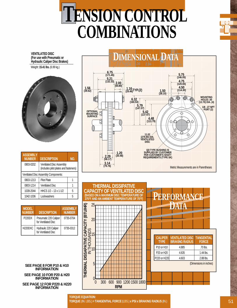
TENSION CONTROL COMBINATIONS
51
PERFORMANCEDATA
0
5
10
15
20
25
0 300 600 900 120015001800
THER
MAL
DIS
SAPA
TIVE
CAP
ACIT
Y (B
TU/H
R)
IN T
HO
USA
ND
S
RPM
THERMAL DISSIPATIVE CAPACITY OF VENTILATED DISC(BASED ON A MAXIMUM DISC TEMPERATURE OF375°F AND AN AMBIENT TEMPERATURE OF 75°F)
TORQUE EQUATION:TORQUE (IN. LBS.) = TANGENTIAL FORCE (LBS.) x PSI x BRAKING RADIUS (IN.)
SEE PAGE 8 FOR P10 & H10INFORMATION
SEE PAGE 10 FOR P20 & H20INFORMATION
SEE PAGE 12 FOR P220 & H220INFORMATION
VENTILATED DISC(For use with Pneumatic or Hydraulic Caliper Disc Brakes)Weight: 15.41 lbs. (6.99 kg.)
(Dimensions in inches)
CALIPER VENTILATED DISC TANGENTIALTYPE BRAKING RADIUS FORCE
P10 or H10 4.885 .70 lbs.
P20 or H20 4.635 1.44 lbs.
P220 or H220 4.603 2.88 lbs.
2.1722.84.30
2.94
G
DIMENSIONAL DATA
1/8 - 27 NPTPORT (2)
1.50(38.10)
4.50(114.30)
4.75(120.65)
5.75(146.05)
MOUNTINGHOLES .50
(12.70) DIA. (4)
4.48(113.79)
5.42(137.67)
5.79(147.07)
6.32(160.53)
11.02(279.90) DIA.VENTILATED
DISC
QD TYPE BUSHING ISSUPPLIED BY CUSTOMERPER CUSTOMER’S SHAFTREQUIREMENTS (TYPE SK)
1.20(30.48)2.29
(58.17)
3.14(79.76)
1.16(29.46)TYP.(2)
2.00(50.80)
5.21(132.33)
6.75(171.45)
1.56(39.62)
OPTIONALMOUNTINGSURFACE
ASSEMBLY NUMBER DESCRIPTION NO.0803-0202 Ventilated Disc Assembly
(includes pilot plates and fasteners)
Ventilated Disc Assembly Components:
0803-1213 Pilot Plate 1
0803-1214 Ventilated Disc 1
1039-2044 HHCS 1/2 – 13 x 1-1/2 5
1042-1036 Lockwashers 5
MODEL ASSEMBLYNUMBER DESCRIPTION NUMBER
P220DX Pneumatic 220 Caliper 0735-0704for Ventilated Disc
H220DXC Hydraulic 220 Caliper 0735-0312for Ventilated Disc
Metric Measurements are in Parentheses

INTENSIFIER
52
FOR USE WITH NON-RETRACTABLE TOL-O-MATIC CALIPERS (UP TO 220 SERIES)
Ideal for operating caliper disc brakes,the intensifier’s higher output pressuremakes it possible to obtain the brakeshigh output handling capacities with-out high pressure hydraulic systems.By operating at these higher pressures,the number of calipers can bereduced.
The intensifier is small, simple andinexpensive, yet operates at a 10:1ratio of output pressure (hydraulicfluid) to inlet pressure (pneumatic).The displacement is 0.44 cubic inches.
The low pressure cylinder is madefrom hard-coated aluminum tubingfor high strength and exceptionallylow friction characteristics.
The low pressure piston seal is of con-ventional U-cup design for reliableoperation.
The high pressure cylinder is made ofaluminum. The high pressure pistonuses an O-Ring of Buna-N, EPR, orVITON to be compatible with mostfluids, to reduce friction and increaselife to millions of cycles.
When air pressure is reduced orremoved, a spring return in the boosterallows the brake puck in the cylinderbrakes to retract, eliminating the needfor retractors in the brakes. The springchamber is vented to eliminate backpressure and return air is filtered toremove entrapment of dirt or otherforeign particles. Athreaded port isprovided for filling or connecting apressure gauge. Bleeding and fillingare external.
NOTE: Not Recommended for SpringApplied Brakes.
*KIT NO. INTENSIFIER NO. SEAL TYPE1770-0002 1770-0000 Buna-N
1770-0003 1770-0001 EPR
1770-0004 1770-0005 Viton
* Kit includes Reservoir, Check Valve and Pipe Nipple

BCII SERIES
53
(All dimensions in inches)
2.1722.84.30
2.94
G
DIMENSIONAL DATA
TUBE MUST BE METAL
CALIPERBleederValve
Check ValveKepner—304C-1
Pipe Nipple1/8 NPT Male X1/8 NPT Male
FreeFlow
5.38 ± .25
2.00 Dia.
RESERVOIR2.5 oz. Cap.Lube Devices, Inc.#R154-1
Check Valve Must Be Mounted
Vertically
INTENSIFIER
4.44
3.00 Sq.
Maximum Inlet AirPressure—100 PSIG
THREE-WAYVALVE
2.00 1.69 .75(Not included in Kit)
(Not included in Kit)
SELECTION
54
Disc brakes are widely used in threeareas: Stopping, retarding (tensioning)and holding. In any application it isnecessary to determine how muchtorque is required, how much heat willbe generated (thus to be dissipated)and the service life anticipated for thepucks or pads. Once these variablesare determined, then find the combi-nation of disc and caliper that willmost economically develop thesecapacities.
DETERMINE THE KINDOF BRAKING TO BE DONE
• Industrial• Tensioning (Constant Slip)• Vehicular
DETERMINE AVAILABLEPRESSURE (LEVERFORCE) AVAILABLE
All torque calculations are based onthe pressure (lever force) available foryour application. Maximum pneumat-ic pressure for Tol-O-Matic caliperdisc brakes is 100 PSI. Maximumhydraulic pressure varies by modelbetween 1,000 PSI and 2,000 PSI.Maximum lever force for mechanicalbrakes varies with model and leverlength. Refer to individual models forpressure (lever force) ratings.
CALCULATE THETORQUE REQUIRED
In braking applications torque is theproduct of tangential force multipliedby the braking radius. Braking radiusis the distance between the centerlineof the braking disc and the center lineof the braking piston(s). Tangentialforce is equal to puck area multipliedby the operating pressure, multipliedby the coefficient of friction of thepuck(s). Torque varies betweendynamic and static (parking) applica-tions, because the coefficient of fric-
tion is different. In a dynamic applica-tion, there is a marked temperatureincrease in the puck, which raises thecoefficient of friction. Because a static(parking) application does not providesuch a temperature increase, it has acoefficient of friction less than that ina dynamic application. For conve-nience, we express the torque formu-lae separately for industrial applica-tions, vehicular applications and ten-sioning applications. See the formulaesection (pages 56-58) to determine thetorque needed for your application.
CALCULATE HEATDISSIPATION REQUIRED
The energy inputs will either beexpressed as BTU input per hour (par-ticularly for tensioning applications)or BTU input per stop. The formulaefor reaching these results are differentfor industrial, tensioning and vehicularbraking. See the formulae section(pages 56-58) to determine the heatgenerated for your application.
DETERMINE MAXIMUMDISC DIAMETER
There are two criteria to determinedisc diameter:
• Envelope Size – how much room isallowed in the design for disc andcaliper. This affects the brakingradius and thus the torque caliperand disc can develop.
• Heat Dissipation Required–Cycle rate and torque are needed todetermine the heat an applicationwill produce per hour, and thus theheat that the disc will need to dissi-pate. Discs will normally dissipateheat at the rate of 3 BTU per hour,per square foot of disc space. Thisassumes a disc temperature of atleast 80° F above ambient tempera-ture. Discs rotating at extreme
speeds may dissipate heat at rates ashigh as 5 BTU per hour, per squarefoot of disc space. If required torque,cycle rate and small envelope sizecombines to create heat dissipationrequirements that are higher than astandard disc will dissipate, yourchoices are: 1.) Athicker disc thatwill act as a heat sink. 2.) Use ofmultiple discs/caliper brakes for theapplication. 3.) Use of a ventilateddisc to dissipate the generated heat.
DETERMINE THE TYPEOF BRAKE POWER
Choose a brake type based on thepower source available (pneumatic,hydraulic, etc.) and whether dynamicor static braking is required for theapplication.
Tol-O-Matic offers brakes powered in5 different ways:
• PneumaticPneumatic actuation is used inindustrial and tensioning applica-tions because pneumatic service iseasily controllable and readily avail-able in most industrial settings.
• HydraulicHydraulic actuated brakes are nor-mally used in vehicular applicationsor where higher torque output isneeded. They may be operated witha variety of fluids including the stan-dard mineral based hydraulic oils,automotive brake fluids and non-flammable phosphate ester fluids(each requires different seals).
• Hydraulic/Mechanical CombosCombination brakes give the addedflexibility to apply mechanical brak-ing as well as hydraulic brakingfrom one caliper.
• MechanicalMechanically actuated brakes are
1.
2.
3.
4.
5.
6.

55
often used as parking or emergencybrakes for vehicles or in situationswhere pneumatic or hydraulic pres-sure is not available. Mechanicalcaliper disc brakes operate when thecam lever is rotated. This pushes theactuating pins against the piston’sbacking plate thus forcing the puckinto the disc.
• Spring AppliedThese brakes require pressure (nor-mally hydraulic) to release it fromthe disc. Braking force is providedby a stack (or stacks) of Bellevillespring washers. The concave wash-ers are capable of storing enormousforce. When the brake is pressurizedthe force moves a piston(s) to com-press the spring washer stack(s),thus releasing the disc. Because theforce applied by the spring stack isreduced as the spring washersexpand, spring applied brakes areused mainly for applications thatrequire occasional holding or stop-ping. They should not be used intension-constant slip applications orcyclic stop industrial applications.
CHOOSE TOL-O-MATICBRAKE SIZE
Tol-O-Matic brakes are grouped bysize. These sizes relate to the puck sizefor each brake. Because maximumpressure (lever force) generated differsbetween the type of brake (pneumatic,hydraulic, etc.) the maximum torqueavailable differs. The graphs on pages6 & 7 will be helpful in determiningthe approximate brake size that willwork for your application. Go to eachindividual brake section to find theequations, and performance graphs forthat brake.
For easy reference, torque output
equations that apply to each series ofbrake are shown at the bottom of thepage. (See sample on this page.) Eachequation features [1.] a constant value,multiplied by [2.] braking radius mul-tiplied by [3.] pressure (lever force).The constant value [1.] is a product offriction material area multiplied by thecoefficient of friction. The brakingradius [2.] for common disc sizesappears on the page with the dimen-sional drawing. The third variable ofthe formula, pressure in PSI (leverforce) [3.] you will need to determine.
Performance data graphs representthese figures for common disc sizes ina convenient, visual way to quicklysee how well each brake size will fityour application.
CHOOSE SINGLE ACTINGOR DOUBLE ACTINGBRAKE
• Double acting brakes feature two“live sides”. Each side has a pistonthat actuates the puck, forcing itagainst the disc. Hydraulic andpneumatic brakes are available indouble acting as well as single act-ing models.
• Single acting brakes have a pistonthat actuates the puck on the “liveside”, forcing it against the disc. The“dead side” has a non-actuated puckattached to the housing. Since onlyone side applies force to the disc, ameans to allow movement to thedisc or caliper must be provided.Spring applied, mechanical andhydraulic/mechanical brakes aregenerally single acting.
DETERMINE MOUNTFOR BRAKE AND DISC
• For Double Acting Brakes
Fixed Caliper Mount/Fixed Disc –Adouble acting caliper can be fixedmounted since both pucks have pis-tons to move them. The disc is alsofixed mounted.
• For Single Acting Brakes
Floating Caliper Mount/Fixed Disc – Afloating mounting bracketpermits the caliper to slightly shiftposition when braking force isapplied. The disc is rigidly mountedto the shaft.
Fixed Caliper Mount/Floating Disc – The caliper is rigidly mount-ed and a floating disc mount attach-es the disc to the shaft. The twoforms of floating disc are: 1.) Discand hub are mounted on a spline onthe shaft. 2.) Hub is rigidly keyed to the shaftand the disc is spring loaded to thehub, providing floating ability.
CONSIDER OPTIONS
Hydraulic brakes may operate with avariety of fluids. Tol-O-Matic brakesuse Buna-N seals most commonly.These seals are suited for use withstandard mineral based hydraulic oil.EPR seals, for use with automotivebrake fluids, are available for mostTol-O-Matic brakes. Some modelsalso give you the choice of VITON®
seals, these seals are suited for usewith nonflammable phosphate esterfluids.
Some Tol-O-Matic caliper disc brakesare available with retractable pistons.Abrake with this feature has a small
7.
8.
9.
10.
DISC SIZING EQUATIONS:DYNAMIC TORQUE (IN. LBS.) = 0.70 x BRAKING RADIUS (IN.) x PRESSURE (PSI)
STATIC (PARKING) TORQUE (IN. LBS.) = 0.40 x BRAKING RADIUS (IN.) x PRESSURE (PSI)BRAKING RADIUS (IN.) = [DIAMETER (IN.) ÷ 2] - 0.675

SELECTION
56
compression spring within the pistonwhich causes it to retract from the discwhen pressure is released. Retractablebrakes are used in applications thatrequire a brake with absolutely no resid-ual drag from the pucks on the disc.
Almost all Tol-O-Matic calipers canbe modified to fit a variety of discthicknesses.
NOTE: Tol-O-Matic retractablebrakes should not be used in vehicularapplications with a master cylinder orwith an intensifier.
DETERMINE LIFEEXPECTANCY OF PUCKS
Another consideration in selecting abrake is the life expectancy of thepucks. This factor is particularlyimportant if the brake is to be placedin a hard to service location, faceslong intervals between servicing, or isto be used in a tensioning-constant slipapplication.
Basically, puck life expectancy is a fac-tor of the amount of heat transmittedthrough the pucks, which may be mea-sured in total number of stops or hoursof life. Both measurements may bereduced to horsepower hours of heatthat the puck must endure. The PuckMaterial Life chart on page 59 showsthe life expectancy of the puck materi-al, plotted on a temperature curve.
Tol-O-Matic offers pucks of two dif-ferent materials. The standard puck ismade of a non-asbestos organic mater-ial and has a peak performance at anoperating temperature of 300°F.Sintered bronze pucks offer peak per-formance in temperatures from 400°to 500°F. See the formulae section todetermine the puck life expectancy foryour application.
PUCK LIFE FORMULAE
RADIUS OF GYRATION FORMULAE
11.
Radius of gyration is the distance from thecenter of rotation at which the entire rotat-ing mass could be concentrated and stillbe equivalent to the actual distributedmass.
Solid Cylinder About its Own Axis
Hollow Cylinder About its Own Axis
[2]
Where:WK 2
e = Equivalent WK2 of the multipleshaft system
WK 2s = WK2 of the shaft assembly on
which the brake disc is mounted WK 2
1 = WK2 of the second shaft assem-bly
Ns = rpm of the shaft on which thebrake disc is mounted
N1 = rpm of the second shaft
The formula for the torque required tobring the multiple shaft system thenbecomes:
[3]T ft lbse s=WK N
t
2
308, . .
WK WK WKNNe S
S
2 212 1
2
= +
+…
kr r2 1
222
2= +r1r1
r2r2
kr2
2
2=
rr
The puck life per cubic inch shown by thecurve in Figure 1 (page 59) is based onhorsepower hours.
To find the life in hours of puck(s):(Primarily for tensioning-constant slipapplications)
Ft. lbs./hr. = (BTU/hr. generated)(778) [17]Refer to Formula [12]
[18]
Refer to Table 2 (page 59) to determinecubic inches of wearable material of vari-ous caliper sizes.
[19]
To find the life in stops of puck(s):When a rotating mass is brought to rest,the kinetic energy removed can be calcu-
lated by the following formulae:
[20]
or
[21]
[22]
[23]
Puck life calculations are estimates anddo not account for foreign contaminantsthat may abrade the puck or disc andreduce wear life. When the life must beknown accurately, field tests should beconducted under actual or simulated ser-vice conditions.
HP hrs StopE
. /, ,
=1 980 000
EWK N
ft lbs=2 2
5872, . .
ETN
ft lbs= π t60
, . .
Life in = Hours
number ofcalipers
cubic in. HP hrs./in
HP hrs. / hr.
3( )
Table 2 Figure 1
HP hrs hrft lbs hr
. / .. . / ., ,
=1 980 000
RADIUS OF GYRATION FOR GEOMETRIC FORMS
CALCULATING SERVICE LIFE OF PUCK(S) / PAD(S)
Life in=Stops
number of
calipers
cubic in. HP hrs./in
HP hrs. / Stop
3
Table Figure 2 1

57
INDUSTRIALAPPLICATIONS FORMULAE
CALCULATION OF TORQUEREQUIRED
Many industrial applications are con-cerned with rotary motions that must bebrought to rest in a specified time the thetorque necessary to satisfy the timerequirement must be determined. Aconve-nient formula used to calculate the torquerequirement of a single shaft system is:
[1]
Where:T = Torque, ft. lbs.W = Weight of rotating member, lbs.K = Radius of gyration of
rotating member, ft.N = rpmt = Stopping time required, seconds
Industrial applications often consist ofmore than one rotating mass system, i.e.,two or more shafts with gears, sheaves,drums, etc. interconnected by operating atdifferent speeds. In such systems the rotat-ing elements must be reduced to a com-mon base. Since the energy of a rotatingmass system is a function of the square ofits rpm, the equivalent WK2 of each rotat-ing member relative to the shaft on whichthe brake disc is mounted can be calculat-ed using the formulae in the Radius ofGyration Section:
CALCULATION OF HEATGENERATION AND DISSIPATIONREQUIRED
Heat is always developed in the disc andpucks of a brake when a rotating or mov-ing body comes to rest. The kinetic energyin BTUs per stop may be expressed in thefollowing formulae:
for a single
shaft system[4]
for a multiple
shaft system [5]
or
[6]
Where:
The weight and specific heat of the puckmaterial is very small compared to the discand can be ignored.
Since the amount of heat dissipated perhour by the disc at a given temperatureabove ambient is considered as beingdirectly proportional to the exposed areaof the disc, disc thickness should be keptsmall.
Standard thicknesses are 5/32" and 1/4".
For the best service life the disc tempera-ture should not exceed 300°F.
Higher disc temperatures can be allowed,however, there will be a reduction in thelife of the friction material. See Figure 1(page 59).
In many applications there are no restric-tions to disc diameter (within reason).Convert your calculated BTU/Stop toBTU/hr. with the following formula:
BTU/hr. = (BTU/stop)(stops/hr.) [7]
Then solving for the number of square feetof exposed disc area to dissipate the heatgenerated:
[8]
Refer to Table 1 (page 59)for selection ofproper disc diameter.
NOTE: The above formula [8] is basedon a 220°F temperature rise and and 80°Fambient temperature. If a higher disc tem-perature is desired refer to formulae [14],[15], [16] in the Tensioning-Constant SlipSection.
If there is a restriction in the disc diame-ter(s) and there is sufficient time betweenstops or multiple of stops for heat dissipa-tion then we can size the disc to act as aheat sink.
[9]
Where:Wd = Weight of disc, lbs.Sp = Specific heat of disc may be
taken as .12 for steel
Refer to Table 1 (page 59)for selection. Ifyour requirement falls outside of the stan-dard(s) you may calculate the requiredthickness based on the maximum allow-able diameter:
Disc Thickness = [10]
Where:A = Area (sq. in.) of maximum allowable
diameter.If it is found the disc thickness is unrealis-tic from an economic or space limitationstandpoint, multiple discs will have to beprovided or force ventilation must be con-sidered.
WdA
inches( )(. )
,28
WdBTU hr
Splbs= / .
( )( ), .
220
Sq Ft Disc AreaBTU hr
. ./=
660
BTU Stop/,
=πTN tS
46 680
BTU Stop e s/, ,
= WK N2 2
4 570 000
BTU Stop/, ,
= WK N2 2
4 570 000T = WK Nt
2
308

SELECTION
58
CALCULATION OF TORQUEREQUIRED
Applications involving tensioning or con-stant drag require a different set of formu-lae since they require a finite time to stop.Tensioning devices are designed to oper-ate over an infinite period of time. Thebasic formula for calculating torque forweb tensioning is:
T= (L) (F) (R), inch lbs.[11]
Where:L = web width, inchesF = tension, lbs./inch of web widthR = maximum roll radius, inches
The basic formula for calculating BTUsgenerated per hour is:
[12]
CALCULATION OF HEATGENERATION AND DISSIPATIONREQUIRED
In tensioning applications the amount ofheat generated must be dissipated as well.Often fpm web velocity is given, this canbe converted to rpm by:
[13]
Where:C = Circumference of roll at maximum
diameter, ft.
Therefore to solve for the sq. ft. of surfacearea of the disc(s):
[14]
The constant of 660 is based on a maxi-mum disc temperature of 300°F.
To develop a constant for higher disc tem-perature:Constant = (3) (temperature rise
above ambient)[15]
The actual disc temperature becomes:Temperature Rise + Ambient, °F [16]
Refer to Table 1. Select disc or discs equalto (or greater than) calculated sq. ft.Remember the higher the disc temperaturethe lower the life of the friction material.See Figure 1.
Sq Ft Disc AreaBTU hr
. ./=
660
rpmfpmC
=
BTU hrT rpm
/ .( )( )
.=
24 75
TENSIONING / CONSTANT SLIPAPPLICATIONS FORMULAE
Unit Conversion TableReference: Handbook of Tables for Applied Engineering Science
Present Units: Convert To: Multiply By:Pounds kilograms 0.45359
Pound-inches Newton-meters 0.11299
Inches millimeters 25.4
PSI pascals 6.895 x 10³
BTU joules 1,054.8
BTU/hr. watts 0.2931
STOP Call 1-800-328-2174
For Assistance That Won’t Stop
Call 1-800-328-2174 For Assistance That Won’t Stop

59
PERFORMANCE DATA
TABLE 1
DISC EXPOSED AREA WEIGHT MAXIMUMDIAMETER SQ. IN. SQ. FT. LBS. BTU / HR.
6.313 62.58 .43 1.37 283.8
8.000 100.53 .70 3.52 462.0
10.000 157.08 1.09 5.46 719.4
12.000 226.20 1.57 7.91 1036.0
16.000 402.12 2.79 14.06 1841.4
EXPOSED AREAS, WEIGHTS AND MAX.BTU/HR. OF COMMONLY USED DISCS
TABLE 3
CAM TRAVEL DATA
0 100 200 300 400 500 600 700
700
600
500
400
300
200
100
0
DISC TEMPERATURE, °F
PUCK
MAT
ERIA
L LI
FE,
HORS
EPOW
ER H
OURS
/ CUB
IC IN
CH
FIGURE 1
PUCK MATERIAL LIFE (NON-ASBESTOS ORGANIC MATERIAL)
TABLE 2
CUBIC INCHES OF WEARABLE FRICTIONMATERIAL OF VARIOUS CALIPERS
CUBICCALIPER INCHES
Series 10 .46
Series 20 .83
Series 220 Aluminum 1.66
Series H-220 Cast Iron 2.35
Series FS-220 Cast Iron w/JK options 2.35
Series FS-220 Aluminum 1.66
Series H-440 4.15
Series FS-440 .83
Series 441 3.71
Series FS-595 .812
Series 960 8.0
MB3 6.06ME-10 and ME-20 Calipers
1. 15° maximum travel when pucks are new and with1/32" gap each side of disc.
2. Periodic tightening of lock nut will reduce travel oflever and will allow 1/4" wear on each puck.
3. 90° maximum travel after 3/16" wear on each puckwithout intermediate tightening of lock nut.
ME-220 Calipers
1. Gap between puck faces and disc when new = .048"total.
2. Angular movement required to actuate brake whennew = 7° 30".
3. Maximum axial movement without intermediateadjustment = .387".
4. Wear allowed before adjustment .104" each side.
MB3 Calipers
1. 0° travel with .500" disc.
2. 90° maximum travel after .125" wear on each sideof pad without intermediate tightening of the locknut.

ORDERING
60
PNEUMATIC #10 SERIES(SEE PAGE 8)
P10SA 5/32" Single Acting 0705-0000
P10SB 1/4" Single Acting 0703-0000
P10SAF 5/32" Single Acting, Floating Bracket 0705-0001
P10SBF 1/4" Single Acting, Floating Bracket 0703-0001
P10DA 5/32" Double Acting 0701-0000
P10DAR 5/32" Double Acting, Retractable Pistons 0708-0000
P10DB 1/4" Double Acting 0702-0000
P10DBR 1/4" Double Acting, Retractable Pistons 0709-0000
P10DER 1/2" Double Acting, Retractable Pistons 0709-0003
P10DL 3/8" Double Acting 0702-0002
P10DLR 3/8" Double Acting, Retractable Pistons 0709-0002
HYDRAULIC #10 SERIES(SEE PAGE 8)
H10SAFC 5/32" Single Acting, Floating Bracket 0705-0011
H10SAFCG 5/32" Single Acting, FtgBrkt,EPR Seals 0705-0009
H10SAC 5/32" Single Acting 0705-0010
H10SACG 5/32" Single Acting, EPR Seals 0705-0008
H10SBC 1/4" Single Acting 0703-0010
H10DAC 5/32" Double Acting 0701-0010
H10DACG 5/32" Double Acting, EPR Seals 0701-0011
H10DBC 1/4" Double Acting 0702-0010
H10DBCG 1/4" Double Acting, EPR Seals 0702-0011
H10DARC 5/32" Double Acting, Retractable Pistons 0708-0010
H10DARCG 5/32" Double Acting, Retr Pist, EPR Seals 0708-0011
H10DBRC 1/4" Double Acting, Retractable Pistons 0709-0010
H10DBRCG 1/4" Double Acting, Retr Pist, EPR Seals 0709-0011
PNEUMATIC #20 SERIES(SEE PAGE 10)
P20SA 5/32" Single Acting 0724-0000
P20SB 1/4" Single Acting 0722-0000
P20SL 3/8" Single Acting 0722-0002
P20SAF 5/32" Single Acting, Floating Bracket 0724-0001
P20SBF 1/4" Single Acting, Floating Bracket 0722-0001
P20DA 5/32" Double Acting 0720-0000
P20DB 1/4" Double Acting 0721-0000
P20DL 3/8" Double Acting 0720-0013
P20DE 1/2" Double Acting 0725-0000
P20DAR 5/32" Double Acting, Retractable Pistons 0728-0000
P20DBR 1/4" Double Acting, Retractable Pistons 0729-0000
P20DLR 3/8" Double Acting, Retractable Pistons 0729-0001
P20DER 1/2" Double Acting, Retractable Pistons 0719-0000
HYDRAULIC #20 SERIES(SEE PAGE 10)
H20SAC 5/32" Single Acting 0724-0010
H20SACG 5/32" Single Acting, EPR Seals 0724-0012
H20SBC 1/4" Single Acting 0722-0010
H20SBCG 1/4" Single Acting, EPR Seals 0722-0013
H20SAFC 5/32" Sng Act, Floating Bracket, Bldr Ftg 0724-0011
H20SAFCG 5/32" Sng Act, Fltg Brkt, Bldr Ftg, EPR Sls 0724-0013
H20SBFC 1/4" Sng Act, Floating Bracket, Bldr Ftg 0722-0011
H20SBFCG 1/4" Sng Act, Fltg Brkt, Bldr Ftg, EPR Sls 0722-0014
H20SLC 3/8" Single Acting 0724-0014
H20DAC 5/32" Double Acting 0720-0010
H20DACG 5/32" Double Acting, EPR Seals 0720-0011
H20DBC 1/4" Double Acting 0721-0010
H20DBCG 1/4" Double Acting, EPR Seals 0721-0011
H20DEC 1/2" Double Acting 0725-0010
H20DECG 1/2" Double Acting, EPR Seals 0725-0011
H20DARC 5/32" Double Acting, Retractable Pistons 0728-0010
H20DARCG 5/32" Double Acting, Retr Pist, EPR Seals 0728-0011
H20DBRC 1/4" Double Acting, Retractable Pistons 0729-0010
H20DBRCG 1/4" Double Acting, Retr Pist, EPR Seals 0729-0011
H20DERC 1/2" Double Acting, Retractable Pistons 0719-0010
H20DERCG 1/2" Double Acting, Retr Pist, EPR Seals 0719-0011
H20DLRC 3/8" Double Acting, Retractable Pistons 0729-0008
PNEUMATIC #220 SERIES(SEE PAGE 12)
P220SA 5/32" Single Acting 0733-0000
P220SB 1/4" Single Acting 0733-0100
P220SE 1/2" Single Acting 0733-0200
P220SAF 5/32" Single Acting, Floating Bracket 0733-0020
P220SBF 1/4" Single Acting, Floating Bracket 0733-0120
P220SEF 1/2" Single Acting, Floating Bracket 0733-0220
P220DA 5/32" Double Acting 0735-0100
P220DB 1/4" Double Acting 0735-0200
P220DE 1/2" Double Acting 0735-0300
A. . . 5/32" Thick DiscB. . . 1/4" Thick DiscC. . . With Bleeder FittingD. . . Double Acting
E. . . 1/2" Thick DiscF. . . Floating Bracket Mount
FS. . . Spring AppliedG. . . EPR Seals
H. . . Hydraulic BrakeI. . . IronJ. . . Retractable PistonK. . . Manual Compensator
MODEL DISC OPTIONS / ASSEMBLYNUMBER THK. DESCRIPTION NUMBER
MODEL DISC OPTIONS / ASSEMBLYNUMBER THK. DESCRIPTION NUMBER
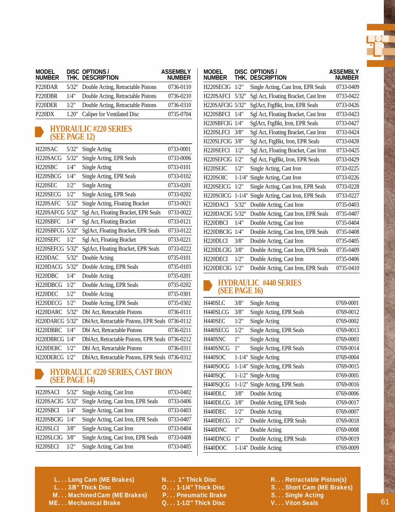
MODEL DISC OPTIONS / ASSEMBLYNUMBER THK. DESCRIPTION NUMBER
MODEL DISC OPTIONS / ASSEMBLYNUMBER THK. DESCRIPTION NUMBER
61
P220DAR 5/32" Double Acting, Retractable Pistons 0736-0110
P220DBR 1/4" Double Acting, Retractable Pistons 0736-0210
P220DER 1/2" Double Acting, Retractable Pistons 0736-0310
P220DX 1.20" Caliper for Ventilated Disc 0735-0704
HYDRAULIC #220 SERIES(SEE PAGE 12)
H220SAC 5/32" Single Acting 0733-0001
H220SACG 5/32" Single Acting, EPR Seals 0733-0006
H220SBC 1/4" Single Acting 0733-0101
H220SBCG 1/4" Single Acting, EPR Seals 0733-0102
H220SEC 1/2" Single Acting 0733-0201
H220SECG 1/2" Single Acting, EPR Seals 0733-0202
H220SAFC 5/32" Single Acting, Floating Bracket 0733-0021
H220SAFCG 5/32" Sgl Act, Floating Bracket, EPR Seals 0733-0022
H220SBFC 1/4" Sgl Act, Floating Bracket 0733-0121
H220SBFCG 5/32" SglAct, Floating Bracket, EPR Seals 0733-0122
H220SEFC 1/2" Sgl Act, Floating Bracket 0733-0221
H220SEFCG 5/32" SglAct, Floating Bracket, EPR Seals 0733-0222
H220DAC 5/32" Double Acting 0735-0101
H220DACG 5/32" Double Acting, EPR Seals 0735-0103
H220DBC 1/4" Double Acting 0735-0201
H220DBCG 1/2" Double Acting, EPR Seals 0735-0202
H220DEC 1/2" Double Acting 0735-0301
H220DECG 1/2" Double Acting, EPR Seals 0735-0302
H220DARC 5/32" Dbl Act, Retractable Pistons 0736-0111
H220DARCG 5/32" DblAct, Retractable Pistons, EPR Seals 0736-0112
H220DBRC 1/4" Dbl Act, Retractable Pistons 0736-0211
H220DBRCG 1/4" DblAct, Retractable Pistons, EPR Seals 0736-0212
H220DERC 1/2" Dbl Act, Retractable Pistons 0736-0311
H220DERCG 1/2" DblAct, Retractable Pistons, EPR Seals 0736-0312
HYDRAULIC #220 SERIES, CAST IRON(SEE PAGE 14)
H220SACI 5/32" Single Acting, Cast Iron 0733-0402
H220SACIG 5/32" Single Acting, Cast Iron, EPR Seals 0733-0406
H220SBCI 1/4" Single Acting, Cast Iron 0733-0403
H220SBCIG 1/4" Single Acting, Cast Iron, EPR Seals 0733-0407
H220SLCI 3/8" Single Acting, Cast Iron 0733-0404
H220SLCIG 3/8" Single Acting, Cast Iron, EPR Seals 0733-0408
H220SECI 1/2" Single Acting, Cast Iron 0733-0405
H220SECIG 1/2" Single Acting, Cast Iron, EPR Seals 0733-0409
H220SAFCI 5/32" Sgl Act, Floating Bracket, Cast Iron 0733-0422
H220SAFCIG 5/32" SglAct, FtgBkt, Iron, EPR Seals 0733-0426
H220SBFCI 1/4" Sgl Act, Floating Bracket, Cast Iron 0733-0423
H220SBFCIG 1/4" SglAct, FtgBkt, Iron, EPR Seals 0733-0427
H220SLFCI 3/8" Sgl Act, Floating Bracket, Cast Iron 0733-0424
H220SLFCIG 3/8" Sgl Act, FtgBkt, Iron, EPR Seals 0733-0428
H220SEFCI 1/2" Sgl Act, Floating Bracket, Cast Iron 0733-0425
H220SEFCIG 1/2" Sgl Act, FtgBkt, Iron, EPR Seals 0733-0429
H220SEIC 1/2" Single Acting, Cast Iron 0733-0225
H220SOIC 1-1/4" Single Acting, Cast Iron 0733-0226
H220SEICG 1/2" Single Acting, Cast Iron, EPR Seals 0733-0228
H220SOICG 1-1/4" Single Acting, Cast Iron, EPR Seals 0733-0227
H220DACI 5/32" Double Acting, Cast Iron 0735-0403
H220DACIG 5/32" Double Acting, Cast Iron, EPR Seals 0735-0407
H220DBCI 1/4" Double Acting, Cast Iron 0735-0404
H220DBCIG 1/4" Double Acting, Cast Iron, EPR Seals 0735-0408
H220DLCI 3/8" Double Acting, Cast Iron 0735-0405
H220DLCIG 3/8" Double Acting, Cast Iron, EPR Seals 0735-0409
H220DECI 1/2" Double Acting, Cast Iron 0735-0406
H220DECIG 1/2" Double Acting, Cast Iron, EPR Seals 0735-0410
HYDRAULIC #440 SERIES(SEE PAGE 16)
H440SLC 3/8" Single Acting 0769-0001
H440SLCG 3/8" Single Acting, EPR Seals 0769-0012
H440SEC 1/2" Single Acting 0769-0002
H440SECG 1/2" Single Acting, EPR Seals 0769-0013
H440SNC 1" Single Acting 0769-0003
H440SNCG 1" Single Acting, EPR Seals 0769-0014
H440SOC 1-1/4" Single Acting 0769-0004
H440SOCG 1-1/4" Single Acting, EPR Seals 0769-0015
H440SQC 1-1/2" Single Acting 0769-0005
H440SQCG 1-1/2" Single Acting, EPR Seals 0769-0016
H440DLC 3/8" Double Acting 0769-0006
H440DLCG 3/8" Double Acting, EPR Seals 0769-0017
H440DEC 1/2" Double Acting 0769-0007
H440DECG 1/2" Double Acting, EPR Seals 0769-0018
H440DNC 1" Double Acting 0769-0008
H440DNCG 1" Double Acting, EPR Seals 0769-0019
H440DOC 1-1/4" Double Acting 0769-0009
L. . . Long Cam (ME Brakes)L. . . 3/8" Thick DiscM. . . MachinedCam (MEBrakes)
ME. . . Mechanical Brake
N. . . 1" Thick DiscO. . . 1-1/4" Thick DiscP. . . Pneumatic BrakeQ. . . 1-1/2" Thick Disc
R. . . Retractable Piston(s)S. . . Short Cam (ME Brakes)S. . . Single ActingV. . . Viton Seals

ORDERING
62
HYDRAULIC #440 SERIES, CAST IRON(SEE PAGE 16) continued
H440DOCG 1-1/4" Double Acting, EPR Seals 0769-0020
H440DQC 1-1/2" Double Acting 0769-0010
H440DQCG 1-1/2" Double Acting, EPR Seals 0769-0021
HYDRAULIC #441 SERIES(SEE PAGE 18)
H441D N/A Double Acting 0774-0000
H441DG N/A Double Acting, EPR Seals 0774-0001
SH441D No. 635 Double Acting, w/#635 0774-0002
SH441DG No.635 Double Acting, EPR Seals, w/#635 0774-0003
HYDRAULIC #960 SERIES(SEE PAGE 20)
H960DECI 1/2" Double Acting, Iron 0778-0003
H960DECIG 1/2" Dbl Acting, Iron, EPR Seals 0778-0004
D960DEVI 1/2" Double Acting, Iron, Viton Seals 0778-0005
H960DXI 1-1/8" Double Acting, Iron 0778-0000
H960DNCI 1" Double Acting, Iron 0778-0011
H960DXCI 3/16" Double Acting, Iron 0778-0012
HYDRAULIC & MECHANICAL #20 SERIES(SEE PAGE 22)
H/ME20MAFC 5/32" Mach Cam, Floating Brkt 0755-0200
H/ME20MBF 1/4" Machined Cam, Floating Bracket 0755-0210
H/ME20SAF 5/32" Short Cam, Floating Bracket 0755-0230
H/ME20SBF 1/4" Short Cam, Floating Bracket 0755-0240
H/ME20LAF 5/32" Long Cam, Floating Bracket 0755-0260
H/ME20LBF 1/4" Long Cam, Floating Bracket 0755-0270
H/ME20MA 5/32" Machined Cam 0755-0300
H/ME20MB 1/4" Machined Cam 0755-0310
H/ME20SA 5/32" Short Cam 0755-0330
H/ME20SB 1/4" Short Cam 0755-0340
H/ME20LA 5/32" Long Cam 0755-0360
H/ME20LB 1/4" Long Cam 0755-0370
H/ME20MAFG5/32" Mach Cam, Floating Brkt, EPR Seals 0755-0500
H/ME20MBFG1/4" Mach Cam, Floating Brkt, EPR Seals 0755-0510
H/ME20SAFG 5/32" Short Cam, Floating Brkt, EPR Seals 0755-0530
H/ME20SBFG 1/4" Short Cam, Floating Brkt, EPR Seals 0755-0540
H/ME20LAFG 5/32" Long Cam, Floating Brkt, EPR Seals 0755-0560
H/ME20LBFG1/4" Long Cam, Floating Brkt, EPR Seals 0755-0570
H/ME20MAG 5/32" Machined Cam, EPR Seals 0755-0600
H/ME20MBG 1/4" Machined Cam, EPR Seals 0755-0610
H/ME20SAG 5/32" Short Cam, EPR Seals 0755-0630
H/ME20SBG 1/4" Short Cam, EPR Seals 0755-0640
H/ME20LAG 5/32" Long Cam, EPR Seals 0755-0660
H/ME20LBG 1/4" Long Cam, EPR Seals 0755-0670
HYDRAULIC & MECHANICAL #220 SERIES(SEE PAGE 24)
H/ME220ACG 5/32" EPR Seals 0744-0630
H/ME220BCG 1/4" EPR Seals 0744-0640
H/ME220LCG 3/8" EPR Seals 0744-0650
H/ME220ECG 1/2" EPR Seals 0744-0660
MECHANICAL #10 SERIES(SEE PAGE 26)
ME10SA 5/32" Short Cam 0732-0000
ME10SAF 5/32" Short Cam., Floating Bracket 0732-0001
ME10SBF 1/4" Short Cam., Floating Bracket 0732-0005
ME10LA 5/32" Long Cam 0732-0003
ME10LAF 5/32" Long Cam, Floating Bracket 0732-0002
ME10LBF 1/4" Long Cam, Floating Bracket 0732-0004
ME10MA 5/32" Machined Cam 0707-0000
ME10MAF 5/32" Machined Cam, Floating Bracket 0707-0001
MECHANICAL #20 SERIES(SEE PAGE 28)
ME20SA 5/32" Short Cam 0731-0000
ME20SB 1/4" Short Cam 0731-0007
ME20SAF 5/32" Short Cam, Floating Bracket 0731-0001
ME20SBF 1/4" Short Cam, Floating Bracket 0731-0004
ME20LA 5/32" Long Cam 0731-0003
ME20LB 1/4" Long Cam 0731-0005
ME20LAF 5/32" Long Cam, Floating Bracket 0731-0002
ME20LBF 1/4" Long Cam, Floating Bracket 0731-0006
ME20MA 5/32" Machined Cam 0726-0000
ME20MB 1/4" Machined Cam 0726-0002
ME20MAF 5/32" Machined Cam, Floating Bracket 0726-0001
ME20MBF 1/4" Machined Cam, Floating Bracket 0726-0003
A. . . 5/32" Thick DiscB. . . 1/4" Thick DiscC. . . With Bleeder FittingD. . . Double Acting
E. . . 1/2" Thick DiscF. . . Floating Bracket Mount
FS. . . Spring AppliedG. . . EPR Seals
H. . . Hydraulic BrakeI. . . IronJ. . . Retractable PistonK. . . Manual Compensator
MODEL DISC OPTIONS / ASSEMBLYNUMBER THK. DESCRIPTION NUMBER
MODEL DISC OPTIONS / ASSEMBLYNUMBER THK. DESCRIPTION NUMBER

MODEL DISC OPTIONS / ASSEMBLYNUMBER THK. DESCRIPTION NUMBER
MODEL DISC OPTIONS / ASSEMBLYNUMBER THK. DESCRIPTION NUMBER
63
MECHANICAL #220 SERIES (SEE PAGE 30)ME220A 5/32" Mechanical Brake 0745-0000
ME220B 1/4" Mechanical Brake 0745-0010
ME220L 3/8" Mechanical Brake 0745-0015
ME220E 1/2" Mechanical Brake 0745-0020
ME220AF 5/32" Floating Bracket 0745-0001
ME220BF 1/4" Floating Bracket 0745-0011
ME220LF 3/8" Floating Bracket 0745-0008
ME220EF 1/2" Floating Bracket 0745-0021
ME220MAI 5/32" Machined Cam, Cast Iron 0745-0002
ME220MBI 1/4" Machined Cam, Cast Iron 0745-0012
ME220MAFI 5/32" Mach Cam, Floating Bracket, Cast Iron 0745-0003
ME220MBFI 1/4" Mach Cam, Floating Bracket, Cast Iron 0745-0013
ME220MLFI 3/8" Mach Cam, Floating Bracket, Cast Iron 0745-0017
ME220MEFI 1/2" Mach Cam, Floating Bracket, Cast Iron 0745-0024
ME220MQFI 1-1/2" Mach Cam, Floating Bracket, Cast Iron 0745-0026
MECHANICAL MB3 SERIES (SEE PAGE 32)MB3 1/2" Mechanical Brake 0790-0000
SPRING APPLIED #20 SERIES (SEE PAGE 34)
FS20A 5/32" Spring Applied 0760-0000
FS20AG 5/32" EPR Seals 0760-0003
FS20B 1/4" Spring Applied 0760-0001
FS20BG 1/4" EPR Seals 0760-0004
FS20PB 1/4" Pneumatically Released 0760-0016
SPRING APPLIED #220 SERIES (SEE PAGE 36)
FS220BA 5/32" Floating Bracket, “B” Strength 0740-0000
FS220BB 1/4" Floating Bracket, “B” Strength 0740-0017
FS220BL 3/8" Floating Bracket, “B” Strength 0740-0019
FS220BE 1/2" Floating Bracket, “B” Strength 0740-0021
FS220CA 5/32" Floating Bracket, “C” Strength 0741-0000
FS220CB 1/4" Floating Bracket, “C” Strength 0741-0018
FS220CL 3/8" Floating Bracket, “C” Strength 0741-0020
FS220CE 1/2" Floating Bracket, “C” Strength 0741-0022
SPRING APPLIED #220 SERIES, IRON (SEE PAGE 38)
FS220BIA 5/32" Floating Bracket, “B” Strength, Iron 0740-0001
FS220BIB 1/4" Floating Bracket, “B” Strength, Iron 0740-0003
FS220BIL 3/8" Floating Bracket, “B” Strength, Iron 0740-0004
FS220BIE 1/2" Floating Bracket, “B” Strength, Iron 0740-0005
FS220BIAJK 5/32" FtgBkt,“B”Stgh,Iron,ManRet,ManComp 0740-0006
FS220BIBJK 1/4" FtgBkt,“B”Stgh,Iron,ManRet,ManComp 0740-0007
FS220BILJK 3/8" FtgBkt,“B”Stgh,Iron,ManRet,ManComp 0740-0008
FS220BIOJK 1-1/4’ FtgBkt,“B”Stgh,Iron,ManRet,ManComp 0741-0034
FS220CIA 5/32" Floating Bracket, “C” Strength, Iron 0741-0005
FS220CIL 1/4" Floating Bracket, “C” Strength, Iron 0741-0007
FS220CIE 1/2" Floating Bracket, “C” Strength, Iron 0741-0008
FS220CIAJK 5/32" FtgBkt,“C”Stgh,Iron,ManRet,ManComp 0741-0009
FS220CIBJK 1/4" FtgBkt,“C”Stgh,Iron,ManRet,ManComp 0741-0010
FS220CILJK 3/8" FtgBkt,“C”Stgh,Iron,ManRet,ManComp 0741-0011
FS220CIEJK 1/2" FtgBkt,“C”Stgh,Iron,ManRet,ManComp 0741-0012
SPRING APPLIED #440 SERIES (SEE PAGE 40)
FS440L 3/8" Iron, Man Wear Comp, Man Retractor 0768-0001
FS440E 1/2" Iron, Man Wear Comp, Man Retractor 0768-0002
FS440N 1" Iron, Man Wear Comp, Man Retractor 0768-0003
FS440O 1-1/4" Iron, Man Wear Comp, Man Retractor 0768-0004
FS440Q 1-1/2" Iron, Man Wear Comp, Man Retractor 0768-0005
SPRING APPLIED #595 SERIES (SEE PAGE 42)
FS595DCIKQ 1-1/2" Double Acting, Iron, Man Wear Comp 0781-0000
FS595DCIKQV 1-1/2" Dbl Act, Iron, Man Comp, Viton Seals 0781-0001
FS595DCIKO 1-1/2" DUAL 0782-0003
L. . . Long Cam (ME Brakes)L. . . 3/8" Thick DiscM. . . MachinedCam (MEBrakes)
ME. . . Mechanical Brake
N. . . 1" Thick DiscO. . . 1-1/4" Thick DiscP. . . Pneumatic BrakeQ. . . 1-1/2" Thick Disc
R. . . Retractable Piston(s)S. . . Short Cam (ME Brakes)S. . . Single ActingV. . . Viton Seals
STOP Call 1-800-328-2174
For Assistance That Won’t Stop
Call 1-800-328-2174 For Assistance That Won’t Stop

APPLICATION DATA
64
E. ADDITIONAL COMMENTS
______________________________________________________
______________________________________________________
______________________________________________________
______________________________________________________
______________________________________________________
______________________________________________________
______________________________________________________
______________________________________________________
______________________________________________________
B. TENSIONING DATA
_____________________________________________________
_____________________________________________________
_____________________________________________________
_____________________________________________________
_____________________________________________________
_____________________________________________________
_____________________________________________________
_____________________________________________________
_____________________________________________________
_____________________________________________________
_____________________________________________________
_____________________________________________________
_____________________________________________________
_____________________________________________________
_____________________________________________________
_____________________________________________________
A. VEHICLE SPECIFICATIONS
PLEASE CONTACT FACTORY
D. GENERAL APPLICATION DATA
FREQUENCY OF STOPS: . . . . . . . . . . . . . . . . . . . . . . . . . . . . . . . . . . . . . . . . . . . __________
COMPLETE OPERATING CYCLE: . . . . . . . . . . . . . . . . . . . . . . . . . . . . . . . . . . __________
MAXIMUM ALLOWABLE DISC DIAMETER: . . . . . . . . . . . . . . . . . . . . . . . ________in.
THICKNESS: . . . . . . . . . . . . . . . . . . . . . . . . . . . . . . . . . . . . . . . . . . . . . . . . . . . . . . . ________in.
TYPE OF ACTUATION:n
Mechanicaln
Spring Applied
n
Pneumaticn
Hydraulic
MAXIMUM HYDRAULIC OR AIR PRESSURE: . . . . . . . . . . . . . . . . . . . . . . ________psi
BACK PRESSURE: . . . . . . . . . . . . . . . . . . . . . . . . . . . . . . . . . . . . . . . . . . . . . . . . . . __________
DRIVE SHAFT APPLICATIONS ONLY:
Gear ratio is______in favor of_______, or against_______the brake
AVAILABLE DISPLACEMENT: . . . . . . . . . . . . . . . . . . . . . . . . . . . . . . . . . . . . . ________in.3
TYPE OF FLUID: ________MAXIMUM TORQUE: _______in. lbs.
AMBIENT TEMPERATURES TO BE ENCOUNTERED: . . . . . . . . . . . . . . __________
LINING LIFE DESIRED: . . . . . . . . . . . . . . . . . . . . . . . . . . . . . . . . . . . . . . . . . . . . . __________
NAME: ____________________________________________________________
TITLE: ____________________________________________________________
FIRM: _____________________________________________________________
ADDRESS: _________________________________________________________
CITY: _____________________________________________________________
STATE: ______________________________ ZIP: _______________________
PHONE: ( ______________) _________________________________________
FAX: ( _________________) _________________________________________
* Recommendation is based on information supplied by the customer. Final accep-tance and approval is the responsibility of the customer after field testing or simu-lation of field testing on the machine it is designed for.
3800 County Road 116 • Hamel, MN 55340 Telephone: (612) 478-8000 • Fax: (612) 478-8080
TYPE OF EQUIPMENT BRAKES WILL BE USED ON:
__________________________________________________________________
__________________________________________________________________
__________________________________________________________________
__________________________________________________________________
__________________________________________________________________
MODEL:________________________ PROJECT #: ______________________
Use this form to request engineering assistance. The data you furnish will enable us to understand your application and recommend* the proper braking equip-ment. When available, please attach prints or dimensional drawings. For best results copy this page first then Fax to: (612) 478-8080 or Mail to:TOL-O-MATIC, INC., 3800 County Road 116, Hamel, MN 55340
TOL-O-MATIC, INC.
C. STATIONARY EQUIPMENT SPECIFICATIONS
CYCLIC STOPS? n
Yes n
No
W = Weight of rotating member
R = Radius of rotating member
WK2 OF ROTATING PARTS__________RPM ____________
DECELERATION NEEDED:
n
Time_______ seconds from _______RPM
n
___________ Radians per second2

Located in west suburban Minneapolis,Minnesota, Tol-O-Matic headquarters(a 100,000 sq. ft. state-of-the-artfacility) is designed for improvedcommunication and manufacturingtechniques to meet customer needstoday and well into the future.
Tol-O-Matic has the resources to help you getwhat you need.
PRODUCTS AND PEOPLE YOU NEED TO GET THE JOB DONE RIGHT.At Tol-O-Matic we have the resources and the experience to give you what you need when you need it.Working together we can find solutions whether it is a new feature, better performance or a whole newproduct line. Our sales department will make sure all your questions are answered. Our engineers will assistyou with application design. Our model shop will make all the tooling and specials you need for a newproduct —not in 6 months or a year—but when you need them.
QUALITY PRODUCTS, COMPETITIVELY PRICED WHEN YOU WANT THEM.Our engineering laboratory pushes our products to the breaking point running them 24 hours a day, 7 days aweek for millions of cycles looking for ways to improve them. They work with R&D to develop newmanufacturing techniques and to perfect new products. For each new product, detailed engineereddrawings are converted into hand crafted sample products for testing, then precision tooling is built on siteby Tol-O-Matic’s own skilled craftsmen with the highest standards of quality, care and dedication to details.The products are tested again by engineering and by selected field representatives. Tol-O-Matic has heavilyinvested in research to guarantee you delivery of the highest quality products not in months or weeks, butwithin days of your order, and with a warranty rate less than .2 of 1%.
UNCONDITIONAL 100% SATISFACTION GUARANTEE.Tol-O-Matic has built its reputation on customer satisfaction. For almost 40 years it has been our policy that,if for any reason you have a problem with any Tol-O-Matic product ordered, we will do whatever it takes tomake sure you are 100% satisfied. Working together we will arrive at a solution that works best for you.
TOL-O-MATIC TRAINING CENTERThere is a Tol-O-Matic product for just about every application that may come your way and it is our goalto remove every obstacle, give you every tool, device and piece of knowledge necessary to learn how tosize and apply Tol-O-Matic products. That is why we supply the most advanced in-depth training in theindustry— free of charge to all our distributors and their customers.

TOL-O-MATIC3800 County Road 116
Hamel, MN 55340http://www.Tolomatic.com
Email: Help@TolomaticPhone: (612) 478-8000
Fax: (612) 478-8080Toll Free: 1-800-328-2174
1
1
2
3
45
6
1.AXIDYNE® ELECTRIC LINEAR MOTION ACTUATORS ANDCONTROLS
• BCES and LSES Screw-Drive Actuators
• BCEB Belt-Drive Actuators• Stepper Control Systems• DC Control Systems
Full Line CAT NO. 3600-4024
• BC3S Screw-DriveActuatorsCAT NO. 3600-4039
• Closed Loop DC SystemCAT NO. 3600-4044
2.RODLESS SLIDES• Linear Slides
CAT NO. 0600-0001• Magnetically Coupled
SlidesCAT NO. 2400-4000
3.GRIPPERS AND ROTARYACTUATORS
• Grippers/Rack and PinionRotary ActuatorsCAT NO. 1900-4000
• Vane Rotary ActuatorsCAT NO. 1800-0006
4. POWER TRANSMISSION• Caliper Disc Brakes
CAT NO. 0701-4000• Adam Disc-plate and
Disc Cone ClutchesCAT NO. 1200-0018
• Float-A-Shaft Gear DrivesCAT NO. 0100-0210
5.ROD CYLINDER SLIDES• H-Block™• Power-Block™• Channel-Block™• U-Block™
Full Line CAT NO. 5109-4008
6.RODLESS CYLINDERS• Magnetically Coupled
CylindersCAT NO. 2400-4000
• Cable CylindersCAT NO. 1001-0219
• Band Cylinder®
BC2 Series™CAT NO. 0510-4000
• Band Cylinder®
BC3 Series™CAT NO. 3400-4000
• Band Cylinder®
BC4 Series™CAT NO. 6900-4000
To order any of these FREE catalogs, call your Tol-O-Matic distributor or the factory at 1-800-328-2174
Tol-O-Matic makes products for anything that moves!


