30
Tolerance of Position Part 1 Hillsborough Community College, Brandon Campus Alessandro Anzalone, Ph.D.

Tolerance of PositionPart 1
Hillsborough Community College, Brandon Campus
Alessandro Anzalone, Ph.D.

Tolerance of Position, Part 1Sections:1. TOP General Information2. TOP Theories3. Common TOP RFS Applications4. Inspecting TOP Applied at RFS5. Common TOP MMC Applications6. Inspecting TOP Applied at MMC7. Summary8. References

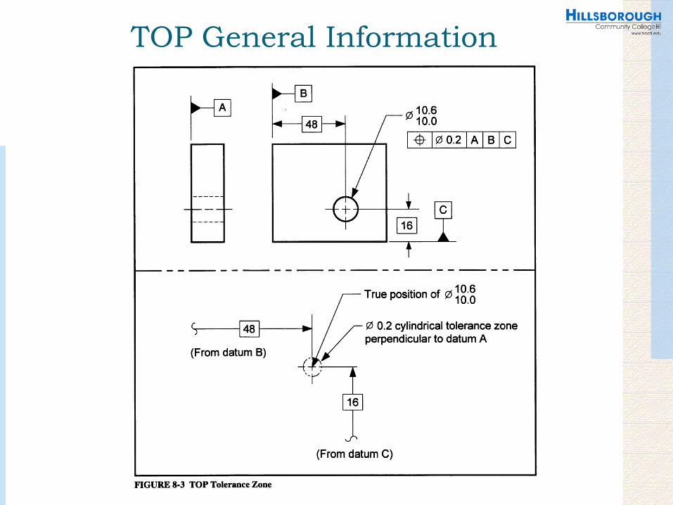
TOP General InformationDefinitions and ConventionsTrue position is the theoretically exact location of a FOS as defined by basic dimensions. A tolerance of position (TOP) control is a geometric tolerance that defines the location tolerance of a FOS from its true position. When specified on an RFS basis, a TOP control defines a tolerance zone that the center, axis, or centerplane of the AME of a FOS must be within. When specified on an MMC or LMC basis, a TOP control defines a boundary—often referred to as the virtual condition—that may not be violated by the surface or surfaces of the considered feature.
TOP General Information

TOP General InformationBasic dimensions define the true position of the toleranced FOS relative to the datums referenced in the feature control frame. In certain cases, the basic dimensions in a TOP application are not specified; they are implied. There are two types of implied basic dimensions common in TOP applications:
1. Implied basic 90° angles—A 90° basic angle applies where centerlines of features in a pattern (or surfaces shown at right angles on a drawing) are located and defined by basic dimensions and no angle is specified.
2. Implied basic zero dimension—Where a centerline or centerplane of a FOS is shown in line with a datum axis or centerplane, the distance between the centerlines or centerplanes is an implied basic zero.

TOP General Information
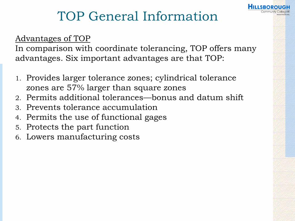
TOP General InformationAdvantages of TOPIn comparison with coordinate tolerancing, TOP offers many advantages. Six important advantages are that TOP:
1. Provides larger tolerance zones; cylindrical tolerance zones are 57% larger than square zones
2. Permits additional tolerances—bonus and datum shift3. Prevents tolerance accumulation4. Permits the use of functional gages5. Protects the part function6. Lowers manufacturing costs

TOP General Information

TOP General InformationTypes of Part Relationships that Can be Controlled with TOPTOP is commonly used to control four types of part relationships:
1. The distance between features of size, such as holes, bosses, slots, tabs, etc.
2. The location of features of size (or patterns of features of size) such as holes, bosses, slots, tabs, etc.
3. The coaxiality between features of size4. The symmetrical relationship between features of size
TOP General Information

TOP TheoriesTOP Theories
Two theories can be used to visualize the effects of a TOP control:
1. The virtual condition boundary theory—A theoretical boundary limits the location of the surfaces of a FOS.
2. The axis theory—The axis (or centerplane) of a FOS must be within the tolerance zone.
Both theories are useful and—in most cases—equivalent. However, the axis theory is most common in RFS TOP applications, and the boundary theory is most common in MMC tolerance of position applications.

TOP Theories

TOP Theories

TOP Theories

TOP Theories

Common TOP RFS Applications

Common TOP RFS Applications

Common TOP RFS Applications

Inspecting TOP Applied at RFS

Common TOP MMC Applications

Common TOP MMC Applications

Common TOP MMC Applications

Common TOP MMC Applications

Common TOP MMC Applications

Inspecting TOP Applied at MMCA TOP applied at MMC can be verified in a number of ways. Variable gages, open inspection, CMM, and functional gaging are all common methods of verifying parts dimensioned with TOP. In this text, we will explain the use of functional gaging.
Functional GageA functional gage is a gage that verifies functional requirements of part features as defined by the geometric tolerances. For example, if holes on a part are intended to fit over studs of a mating part, a function of the holes would be to assemble over the studs. To verify the location of the holes, a functional gage that simulates the studs of the mating part could be used.A functional gage does not provide a numerical reading of a part parameter. A functional gage often provides a “pass” or “fail” assessment of a part feature. A functional gage is often referred to as an attribute gage or a fixed gage because it checks attributes of a part FOS (location and orientation).
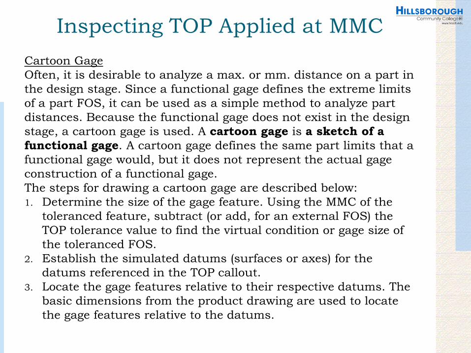
Inspecting TOP Applied at MMCCartoon GageOften, it is desirable to analyze a max. or mm. distance on a part in the design stage. Since a functional gage defines the extreme limits of a part FOS, it can be used as a simple method to analyze part distances. Because the functional gage does not exist in the design stage, a cartoon gage is used. A cartoon gage is a sketch of a functional gage. A cartoon gage defines the same part limits that a functional gage would, but it does not represent the actual gage construction of a functional gage.The steps for drawing a cartoon gage are described below:1. Determine the size of the gage feature. Using the MMC of the
toleranced feature, subtract (or add, for an external FOS) the TOP tolerance value to find the virtual condition or gage size of the toleranced FOS.
2. Establish the simulated datums (surfaces or axes) for the datums referenced in the TOP callout.
3. Locate the gage features relative to their respective datums. The basic dimensions from the product drawing are used to locate the gage features relative to the datums.

Inspecting TOP Applied at MMC

Inspecting TOP Applied at MMC

Summary

Referenceshttp://www.tarleton.edu/~tbarker/2153/Notes_Handouts/CHAP12_GD&T.pdfhttp://www.etinews.com/tip_mnth_rulespostol.htmlhttp://www.efunda.com/designstandards/gdt/2D_bonus_tol.cfmhttp://www.jjjtrain.com/vms/geotol_true_pos_tol_zone/geotol_tp_00.htmlhttp://www.toolingu.com/definition-350310-12380-position-tolerance.html


