115 Tomasz Rydzkowski and Iwona Michalska-Pozoga 4.1 Principles of Disc and Screw-disc Extrusion One of the main processing problems of recycling is the expensive requirement of segregating difficult to identify polymeric materials, i.e., items made from recyclates, which are characterised by poor performance. The solution to this problem is to develop technologies for processing recyclates and its mixtures. The proper selection of techniques and processing conditions may allow obtaining products characterised by more favourable properties. The screw-disc extruder has unique features including good mixing intensity, and an adjustable chink between the front of the screw and cylinder cover, which may encourage its use in the processing of recycled polymeric materials, and its mixtures and composites. The content of this chapter includes a description of the screw-disc extruder and analysis of extruder structures, in addition to detailing the phenomena occurring in the disc zone of a screw-disc extruder. It also presents the effect of this type of extrusion on the resultant extrudate properties. 4.2 A Review of Screw and Screw-disc Extruder Construction Among the few works concerning disc extrusion are the publications of Maxwell and Scalor [1], Prokunin [2, 3], Leonov [4], Lukacz [5] and Kocherov [6, 7], and also Kato and Tomita [8, 9]. References can be found, in databases, to disc extrusion patents which were filed in England in 1978 (British Patent PT68659) [10], and in Germany in 1978 (German Patent DE2732173) [11] and 1986 (German Patent DE2759878 C3) [12]. They were referred to as processing equipment specifically for hyper viscous materials. Disc extruders have also been known as ‘schield extruders’ (Polish Patent PL83102 1975) [13]. One of the theories of disc extrusion was based on the work of Prokunin. In his 4 Effective Screw-disc Extrusion in the Processing of Recycled Polymers and its Composites
Transcript
115
Tomasz Rydzkowski and Iwona Michalska-Pozoga
4.1 Principles of Disc and Screw-disc Extrusion
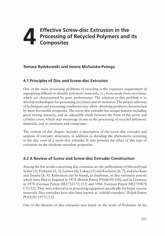
One of the main processing problems of recycling is the expensive requirement of segregating difficult to identify polymeric materials, i.e., items made from recyclates, which are characterised by poor performance. The solution to this problem is to develop technologies for processing recyclates and its mixtures. The proper selection of techniques and processing conditions may allow obtaining products characterised by more favourable properties. The screw-disc extruder has unique features including good mixing intensity, and an adjustable chink between the front of the screw and cylinder cover, which may encourage its use in the processing of recycled polymeric materials, and its mixtures and composites.
The content of this chapter includes a description of the screw-disc extruder and analysis of extruder structures, in addition to detailing the phenomena occurring in the disc zone of a screw-disc extruder. It also presents the effect of this type of extrusion on the resultant extrudate properties.
4.2 A Review of Screw and Screw-disc Extruder Construction
Among the few works concerning disc extrusion are the publications of Maxwell and Scalor [1], Prokunin [2, 3], Leonov [4], Lukacz [5] and Kocherov [6, 7], and also Kato and Tomita [8, 9]. References can be found, in databases, to disc extrusion patents which were filed in England in 1978 (British Patent PT68659) [10], and in Germany in 1978 (German Patent DE2732173) [11] and 1986 (German Patent DE2759878 C3) [12]. They were referred to as processing equipment specifically for hyper viscous materials. Disc extruders have also been known as ‘schield extruders’ (Polish Patent PL83102 1975) [13].
One of the theories of disc extrusion was based on the work of Prokunin. In his
4 Effective Screw-disc Extrusion in the Processing of Recycled Polymers and its Composites
116
Recycled Polymers: Chemistry and Processing, Volume 1
theory, Prokunin applied the cylindrical coordinate system, in which he described the material flow generated by the Weissenberg effect. Such a system has been developed and experimentally tested by Maxwell and Scalor [1]. A diagram of such a device is shown in Figure 4.1.
21
Q
Q
Q
ω
3
54
d'
R'2R'1
h' 1
L'
h'
Figure 4.1 Schematic diagram of a disc extruder according to the Prokunin theory: 1) material (melt); 2) motionless, flat disc; 3) movable ring; 4) movable bowl and
5) nozzle. Where: Q − intensity of polymer flow, h − gap/chink size, L − length of the nozzle, d − diameter of the nozzle, R − radius of the stationary disc and w-angular − speed of a disc. Reproduced with permission from A.N Prokunin,
Prokunin, based on the analysis of material traffic in the disc system and on the material rheology, formulated equations describing the mean flow rate and the pressure of the material in the nozzle. The analysis carried out showed that it is possible to construct disc extruder systems based on the Weissenberg effect, but the obtained pressure and performance are very small, which makes it impossible for technical applications [3].
Another issue considered by Prokunin, Zadvornykh and Sysoev, associated with the screw systems, is the analysis of the changes in temperature and shear stresses generated in the liquid located between the two flat discs (movable and fixed) [3]. The simplest design of the extruder disc, compatible with Prokunin's considerations, is shown in Figure 4.2 [14, 15].
A characteristic feature of this type of extrusion is that it takes place as a result of the rotation of the circular-disc elements length/diameter (L/D) ratio being much less
117
Effective Screw-disc Extrusion in the Processing of Recycled Polymers and its Composites
(several tens of times) than the L/D ratio in the case of classical screw plasticising. In this design, extrusion was based on directly delivering the material to the disc zone between the rotatable disc and the stationary cylinder cover (extruder housing).
2
1
3
5
4
Figure 4.2 Disc plasticising system: 1) tray; 2) cylinder cover; 3) electric heater; 4) nozzle and 5) shield. Reproduced with permission from R. Sikora in
The movement and homogenisation of the material in the circular zone of the extruder correspond to the Weissenberg effect. During the rotation of the disc, relative to the stationary shield, the movement of the plasticised and homogenised material is opposite to the centrifugal force towards the centre of the chink disc. The disc zone produces its own pressure by rolling the long polymer chains, which draws the material to the central part of the disc and pushes it through a nozzle to the outside. The advantage of this system was the ability to influence the degree of homogenisation of the material. The high degree of homogenisation in the disc zone is due to the fact that single streams of material from the entire circumference of the disc, which has a large diameter, are combined in the outlet channel, which has a small diameter (extruder die). A major drawback is getting low pressure and,
118
Recycled Polymers: Chemistry and Processing, Volume 1
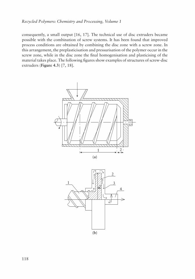
consequently, a small output [16, 17]. The technical use of disc extruders became possible with the combination of screw systems. It has been found that improved process conditions are obtained by combining the disc zone with a screw zone. In this arrangement, the preplasticisation and pressurisation of the polymer occur in the screw zone, while in the disc zone the final homogenisation and plasticising of the material takes place. The following figures show examples of structures of screw-disc extruders (Figure 4.3) [7, 18].
21
(a)
1
2
3
4
r 0
RT
(b)
119
Effective Screw-disc Extrusion in the Processing of Recycled Polymers and its Composites
2
1
(c)
21
(d)
Figure 4.3 Schematic structure of screw-disc plasticising systems: a-c) a common drive on screw and shield, and d) separate drive on screw and disc: 1) screw zone; 2) disc zone; 3) housing and 4) cylinder cover nozzle. r0: radius of the nozzle and
RT: radius of the disc. Reproduced with permission from J.E. Lukaczow, A.D. Petuchow and W.A. Senatos in Oborudowanie dla Proizwodstwa
Figures 4.3a–c show the structure having a common drive for the screw and the disc, while Figure 4.3d shows a structure having a separate drive for the screw and disc.
120
Recycled Polymers: Chemistry and Processing, Volume 1
The combination of the two zones creates the possibility of obtaining high pressure, extrusion performance and a high degree of homogenisation.
The first mention of the useful screw-disc structures appeared in the literature in the late 1960s and 1970s. The aforementioned extruders are shown below (Figures 4.4–4.6) and have been studied at the Technical University of Kiev (Ukraine). The first of the presented structures (Figure 4.4) displays three distinct zones: two screw zones (supply and plasticising) and a disc zone of homogenisation [5].
2
4
56
7
3 1
Figure 4.4 Schematic of the screw-disc extruder: 1) disc; 2) screw; 3) cylinder; 4) tray; 5) drive system; 6) electric heaters and 7) housing.
In this system, the extruder screw is responsible for the transportation of material and its plasticisation. The disc acts as a mixing and homogenising zone. In 1976, a linear structure of the plasticising screw-disc system was presented (Figure 4.5), in which structurally there are two screws and a shield/disc. The first screw is located before the disc (under the feeding chopper) (2), has a large diameter, a very small L/D ratio and a very small pitch, which serves as a feeding zone. The second screw is located behind the disc (6) which generates pressure and pushes material outside the extruder. The disc (3) is designed with peripheral walls (4) to facilitate the entry of material into the chink zone, in this design the disc acts as a plasticising area.
121
Effective Screw-disc Extrusion in the Processing of Recycled Polymers and its Composites
Another design is the angled screw-disc system which was developed in 1977 (Figure 4.6). In this arrangement, there are two screws, one of them (under the charging chopper) (2) acts as a power supply, and a second screw (7), located behind the disc (4), generates the pressure needed to push the material outwards. The disc zone in this case, as shown in Figure 4.5, is used for plasticising the processed material. The difference between this and the structure described above is shown in Figure 4.6, i.e., there is no classical Weissenberg effect, since the chink is wide and has disc-shaped plastic scrapers (6) [14].
Preliminary results have confirmed suspicions that the screw-disc extruder enables obtaining an extrudate of more favourable functional properties than those obtained using classical screw extrusion [7, 19]. Despite the satisfactory performance such structures are not applied within industry.
122
Recycled Polymers: Chemistry and Processing, Volume 1
6) plastic harrow; 7) the final plasticising screw; 8) final plasticising cylinder; and 9) nozzle. Reproduced with permission from R. Sikora in Processing of
Based on the experience of earlier scientists and their considerations involving the simulation and optimisation of the extrusion process, work carried out in the Department of Food Engineering and Plastics at Koszalin University of Technology in 1995 established unique extruder design combinations, which had a screw and a disc zone. It was created as a result of Diakun's theoretical analysis [20], which was the basis of studies into the analysis of the structure and parameters of the extruder and its optimisation, including design features, energy balances, and pressure and temperature conditions in the plasticising system. Based on the obtained results the geometric features of the extruder, designed mainly for polyolefins processing, were determined. Design and construction led to the building of an experimental screw-disc extruder, patented in 1989 (Polish Patent No.PL150688 [21]) (Figure 4.7). It is an original design solution, based on performed calculations, optimisation and simulations [22].
123
Effective Screw-disc Extrusion in the Processing of Recycled Polymers and its Composites
66
7
4 14
12
13
1
3
2
9
5
11
1212
10
8
Figure 4.7 Longitudinal cross-section of the plasticising autothermal, experimental screw-disc extruder: 1) head chink (disc zone); 2) barrel cover; 3) head of the
screw; 4) bushing; 5) bearing; 6) keyway; 7) drive shaft; 8) cold zone of the barrel; 9) hot zone of the barrel; 10) cold zone of the screw; 11) hot zone of the screw;
12) thermal insulators; 13) electric heater and 14) cooling band
Figure 4.8 View of the plasticising system with the drive unit. Reproduced with permission from I. Michalska-Pożoga in Influence of the Disc Mechanism
Plasticization in Screw-disc Extruder on Mechanical Proprieties Material, Koszalin University of Technology, Koszalin, Poland, 2006, PhD Dissertation.
Recycled Polymers: Chemistry and Processing, Volume 1
a) b)
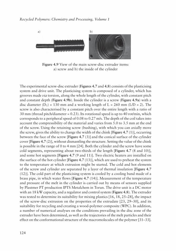
Figure 4.9 View of the main screw-disc extruder items: a) screw and b) the inside of the cylinder
The experimental screw-disc extruder (Figures 4.7 and 4.8) consists of the plasticising system and drive unit. The plasticising system is composed of a cylinder, which has grooves made via torsion, along the whole length of the cylinder, with constant pitch and constant depth (Figure 4.9b). Inside the cylinder is a screw (Figure 4.9a) with a disc diameter (DT) = 130 mm and a working length of L = 260 mm (L/D = 2). The screw is also characterised by a constant pitch over the entire length with a ratio of 30 mm (thread pitch/diameter = 0.23). Its rotational speed is up to 40 rot/min, which corresponds to a peripheral speed of 0.08 to 0.27 m/s. The depth of the coil takes into account the compressibility of the material and varies from 5.0 to 3.5 mm at the end of the screw. Using the retaining screw (bushing), with which you can axially move the screw, gives the ability to change the width of the chink [Figure 4.7 (1)], occurring between the face of the screw [Figure 4.7 (3)] and the conical surface of the cylinder cover [Figure 4.7 (2)], without dismantling the structure. Setting the value of the chink is possible in the range of 0 to 4 mm [24]. Both the cylinder and the screw have some cold segments, representing about two-thirds of the length [Figure 4.7 (8 and 10)], and some hot segments [Figure 4.7 (9 and 11)]. Two electric heaters are installed on the surface of the hot cylinder [Figure 4.7 (13)], which are used to preheat the system to the temperature at which extrusion might be started. The cold and hot elements of the screw and cylinder are separated by a layer of thermal insulation [Figure 4.7 (12)]. The cold part of the plasticising system is cooled by a cooling band made of a brass pipe, in which water flows [Figure 4.7 (14)]. Measurement of the temperature and pressure of the melt in the cylinder is carried out by means of sensors supplied by Plastmer PT production IPTS Metalchem in Torun. The drive unit is a DC motor with an 18 kW capacity, and a regulator and control system (Figure 4.8). The extruder was tested to determine its suitability for mixing plastics [16, 18, 25–28], the impact of the screw-disc extrusion on the properties of the extrudate [23, 29–30], and its suitability for recycling and creating a wood-polymer composite (WPC). In addition, a number of numerical analyses on the conditions prevailing in the disc zone of the extruder have been determined, as well as the trajectories of the melt particles and their effect on the conformational structure of the macromolecules of the polymer [31–33].
125
Effective Screw-disc Extrusion in the Processing of Recycled Polymers and its Composites
4.3 Movement of Polymer Particles in the Disc Zone of the Screw-disc Extruder
The following section focuses only on the movement of plastic particles in the disc zone of the screw-disc extruder, as the movement of material in the screw zone is very accurately described in the literature detailing classical screw extruders.
During the extrusion process in the disc zone, the plasticised material is located between the conical end of the rotating screw and the stationary (also conical) shield of the cylinder cover. The circular zone of the screw-disc extruder replaced two zones found in the classical screw extruder, namely the transformation and homogenisation zones. Thus, the conditions and the flow trajectories in the screw-disc system are completely different from the classical design.
In the case of the disc zone, material flows in the radial direction r from the outer diameter to the central opening DT (Figure 4.10a). The movement of material in the disc zone of the screw-disc extruder results from the superposition of two streams: pressure and drag (Figure 4.10b).
a) b) wrx
wS
wo
ω
ϕ
w
DTwox
wo
xx
r
r
12
o
ws
Figure 4.10 Simplified disc zone: a) scheme and b) velocity distribution in the clearance between the discs: 1) rotary disc and 2) casing (pressure stream velocity
vector (wrx), drag stream velocity vector (wox), peripheral direction (o), radial direction (r), the chink (Ws), disc diameter (DT), velocity in the circumferential
direction vector (wo), angular speed of a disc (j), location in the chink depth (x) and efficiency (W
:
). Reproduced with permission from T. Rydzkowski and I. Michalska-Pożoga in Plastic in Machine Design, Cracow University of
Recycled Polymers: Chemistry and Processing, Volume 1
The pressure stream is the result of the plastic flow being forced under pressure generated by the screw. The aforementioned flow velocity distribution is parabolic wrx (Figure 4.10b), hence the speed and efficiency varies with the radius; the formula defining the velocity distribution of the material wrx in the radial direction at radius r where the depth of the chink is x (Equation 4.1) is given by:
( )wr WW W x x3
rx
S
S3
2##
#r
= -:
(4.1)
The drag stream results from the relative motion of the rotating disc [Figure 4.10 (1)] and the stationary disc of the housing [Figure 4.10a (2)]. Plastic particles at the rotating disc are moving at the speed of the disc. The speed decreases in the x direction to the stationary housing, wherein the particles have a speed close to zero. The distribution is linear wox (Figure 4.10b). A model for determining the velocity distribution of the dragged stream (Equation 4.2) is:
w rWx1oxS
~= -` j (4.2)
and the angular velocity of movement of the material particle determines the following formula (Equation 4.3):
Wx1oxS
~ ~= -` j (4.3)
The direction of the velocity of pressure and dragged streams are orthogonal to each other (Figure 4.10b).
Models describing the trajectory of melted plastic particles in the disc zone at polar coordinates (r, j), are as follows: the equation describing the beam which contains the melted polymer particle (Equation 4.4) and the angle corresponding to the radius (Equation 4.5) [31] is:
rD
w dt2T
rx= - # (4.4)
127
Effective Screw-disc Extrusion in the Processing of Recycled Polymers and its Composites
dtox{ ~= # (4.5)
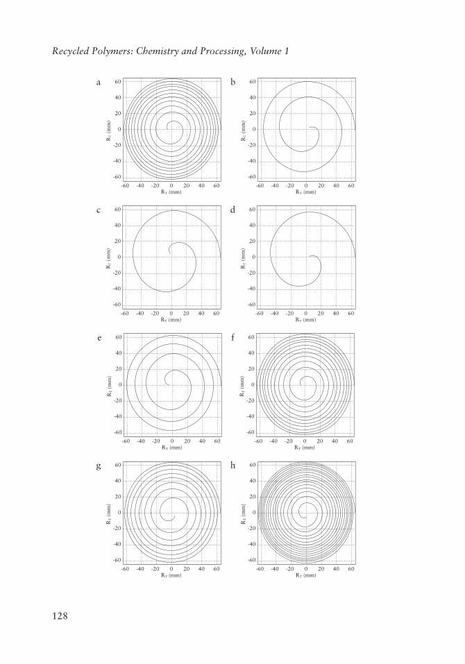
The superposition of these two streams results in the formation of the spiral motion of plastic particles in the disc zone of the screw-disc extruder. Observations show that the nature of the material particle trajectories depends on the following factors: efficiency W
:
(Figures 4.12a–c), the width of the chink Ws (Figures 4.12d–f), the angular velocity w (Figures 4.12g-i) and the location of the particles in the disc chink x (Figures 4.12j–l). The location of the particles in the disc chink is determined by its distance from the surface of the movable face of the screw (Figure 4.11).
ω
∆ϕ
0.8 WS
X
DT
d/2
r
0.5 WS
0.2 WS
1
2
Figure 4.11 The initial location of the polymer chain in the simulation calculations: 1) forehead of the screw; 2) stationary cylinder cover (the width of the disc chink
zone (Ws), disc diameter (DT), the initial radius of (r), the output radius (d/2), location in the chink depth (x) and angular velocity of the disc (w).
Recycled Polymers: Chemistry and Processing, Volume 1
a 60
40
20
0
RT (
mm
)
RT (mm)
-20
-40
-60
-60 -40 -20 0 20 40 60
b 60
40
20
0
RT (
mm
)
RT (mm)
-20
-40
-60
-60 -40 -20 0 20 40 60
c 60
40
20
0
RT (
mm
)
RT (mm)
-20
-40
-60
-60 -40 -20 0 20 40 60
d 60
40
20
0
RT (
mm
)
RT (mm)
-20
-40
-60
-60 -40 -20 0 20 40 60
e 60
40
20
0
RT (
mm
)
RT (mm)
-20
-40
-60
-60 -40 -20 0 20 40 60
f 60
40
20
0
RT (
mm
)
RT (mm)
-20
-40
-60
-60 -40 -20 0 20 40 60
g 60
40
20
0
RT (
mm
)
RT (mm)
-20
-40
-60
-60 -40 -20 0 20 40 60
h 60
40
20
0
RT (
mm
)
RT (mm)
-20
-40
-60
-60 -40 -20 0 20 40 60
129
Effective Screw-disc Extrusion in the Processing of Recycled Polymers and its Composites
i 60
40
20
0R
T (
mm
)
RT (mm)
-20
-40
-60
-60 -40 -20 0 20 40 60
j 60
40
20
0
RT (
mm
)
RT (mm)
-20
-40
-60
-60 -40 -20 0 20 40 60
k 60
40
20
0
RT (
mm
)
RT (mm)
-20
-40
-60
-60 -40 -20 0 20 40 60
l 60
40
20
0R
T (
mm
)
RT (mm)
-20
-40
-60
-60 -40 -20 0 20 40 60
Figure 4.12 Trajectory of particle motion in a screw-disc plasticising system: a) W
:
= 3.33 kg/h, Ws = 3.0 mm, x = 0.2 mm, RT = 65 mm, r0 = 5 mm, w = 2 rad/s; b) W
:
=16.6 kg/h, Ws = 3.0 mm, x = 0.2 mm, RT = 65 mm, r0 = 5 mm, w = 2 rad/s; c) W
:
= 26.4 kg/h, Ws = 3.0 mm, x = 0.2 mm, RT = 65 mm, r0 = 5 mm, w = 2 rad/s; d) W
:
= 3.33 kg/h, Ws = 0.3 mm, x = 0.2 mm, RT = 65 mm, r0 = 5 mm, w = 2 rad/s; e) W
:
= 3.33 kg/h, Ws = 1.0 mm, x = 0.2 mm, RT = 65 mm, r0 = 5 mm, w = 2 rad/s; f) W
:
= 3.33 kg/h, Ws = 3.0 mm, x = 0.2 mm, RT = 65 mm, r0 = 5 mm, w = 2 rad/s; g) W
:
= 3.33 kg/h, Ws = 3.0 mm, x = 0.2 mm, RT = 65 mm, r0 = 5 mm, w=1.5 rad/s; h) W
:
= 3.33 kg/h, Ws = 3.0 mm, x = 0.2 mm, RT = 65 mm, r0 = 5 mm, w = 3 rad/s; i) W
:
= 3.33 kg/h, Ws = 3.0 mm, x = 0.2 mm, RT = 65 mm, r0 = 5 mm, w = 6 rad/s; j) W
:
= 3.33 kg/h, Ws = 3.0 mm, x = 0.2 mm, RT = 65 mm, r0 = 5 mm, w = 2 rad/s; k) W
:
= 3.33 kg/h, Ws = 3.0 mm, x = 0.5 mm, RT = 65 mm, r0 = 5 mm, w = 2 rad/s and l) W
:
= 3.33 kg/h, Ws = 3.0 mm, x = 0.8 mm, RT = 65 mm, r0 = 5 mm, w = 2 rad/s
Another issue which has been analysed is the impact of the conditions in the disc zone of the extruder on naturally tangled polymer chains. The average estimated conformational length of the molecules in low-density polyethylene (LDPE), which is 60 nm (according to Flory [36]), was the basis for simulations of movement in the
130
Recycled Polymers: Chemistry and Processing, Volume 1
disc zone at two points with a distance from each other equal to the calculated value of the conformational length of the molecule.
The movement of these points from the outer diameter of the disc RT = 65 mm (point A in Figure 4.13) to the edge of the central opening, of 20 mm diameter, shows the diversity of the movement path for the analysed points. Simulation results confirm that naturally tangled polymer chains, during their stay in the disc zone under the impact of shear forces, may be stretched, which is shown in Figure 4.14. The stretching of a naturally curled polymer chain is achieved by the presence of a large, variable velocity gradient that affects the considerable trajectory variation of polymer chain ends (Figure 4.13).
60
40
20
0
RT (
mm
)
RT (mm)
-20
-40
-60
-60 -40 -20 0 20 40 60
A
Figure 4.13 The trajectories of movement of two points located at a distance equal to the LDPE molecule conformational length from each other. A − is the initial
position of the polymer chain in a disc zone
This leads to good homogenisation of the material and an extension of the conformational length from several-fold to 10-fold, this results in a supermolecular polymer structure reorganisation which should enhance its performance [31, 32]. It was found that the greatest impact on the development of polymer chains and the change of supermolecular structure is the width of the chink in the disc zone; resulting
131
Effective Screw-disc Extrusion in the Processing of Recycled Polymers and its Composites
from the shear rate occurring in this area and is associated with shear stress. A small width of the chink causes high shear, while a large width of the disc zone results in low values of shear stress, which impact on the nature of the polymer chains.
a) b)
A A
∆1
B B
Figure 4.14 Model macromolecular behaviour under shear impact: A and B are the ends of the macromolecule, a) the velocity gradient and b) a diagram of extending the length of the macromolecule D1 under the influence of tangential
forces. Reproduced with permission from T. Rydzkowski and I. Michalska-Pożoga in Plastic in Machine Design, Cracow University of Technology, Cracow, Poland,
Based on these findings and analysis it can be concluded that the processing properties of the disc zone of the screw-disc extruder affect the organisation of the polymer chains and thus the mechanical properties of the processed polymer material. This unique phenomena in the disc zone of the screw-disc extruder makes it particularly suitable for the processing of polymeric materials during recycling.
Based on analysis of the literature, and results of experimental and simulation studies, it was found that the screw-disc extruder can control the intensity of mixing and thus influences the varying structure of the obtained extrudate. Hence, the process is of particular use for mixtures of different materials and their composites, which are commonly used in the technology of polymeric materials recycling.
Studies were performed to confirm the theoretically predicted characteristics of the effects of screw-disc extrusion on processed original material, mixtures of recyclates and WPC. The results were compared with the effects of classical screw extrusion.