64
Tomb Raider TR-120-1001 Operation & Service Manual Version 6.1 * Read this manual before use
Tomb Raider
TR-120-1001
Operation & Service Manual
Version 6.1
* Read this manual before use

Tomb Raider Manual V6.1
2 | P a g e
General Remark
If you encounter any difficulties or if you need support on how to update and/ or install your
Tomb Raider product, we invite you to contact your local distributor or reach us at
[email protected] or by calling our support line +1-450-824-1671
Adrenaline Amusements Team
Adrenaline Amusements
2273 Antonio-Héroux street
Terrebonne, QC
Canada
J6X 4R3
Tomb Raider Manual V6.1
3 | P a g e
Table of Contents
Contents
General Remark .................................................................................................. 2
Table of Contents ................................................................................................ 3
Chapter 01 - Preface ........................................................................................... 5
Precaution for Game Operation .................................................................................................. 5
Safety ........................................................................................................................................... 6
Environmental Conditions ........................................................................................................... 6
Operating & Voltage .................................................................................................................... 6
Maintenance Warning ................................................................................................................. 7
Chapter 02 – Unit Features ................................................................................. 8
Hardware Features ...................................................................................................................... 8
Cabinet Facts ............................................................................................................................... 8
Chapter 03 – Unit Installation ............................................................................. 9
Parts included .............................................................................................................................. 9
Assembling your Tomb Raider Unit .......................................................................................... 10
Cabinet & Side Panels Assembly ............................................................................................... 11
Screen Assembly ....................................................................................................................... 16
Header Assembly ....................................................................................................................... 19
Chapter 04 – Operator Menu ............................................................................ 29
Operator Menu ......................................................................................................................... 29
Chapter 05 – Service & Repair ........................................................................... 31
Computer Connections ............................................................................................................. 31
Projector Connections ............................................................................................................... 32
Projector Settings ...................................................................................................................... 33
Gun Controller ID Remapping ................................................................................................... 35
Troubleshooting ........................................................................................................................ 37

Tomb Raider Manual V6.1
4 | P a g e
Video Troubleshooting ........................................................................................................................ 37
Audio Troubleshooting ....................................................................................................................... 37
Wireless Internet Configuration ................................................................................................ 38
Operator Settings keeps resetting trouble ............................................................................... 39
Computer not powering at boot ............................................................................................... 40
Chapter 06 - Parts ............................................................................................. 41
Cabinet Parts ............................................................................................................................. 41
Other Cabinet Parts ................................................................................................................... 42
Wood module parts .................................................................................................................. 43
Screen Assembly ....................................................................................................................... 44
Screen Repair Kit .......................................................................... Error! Bookmark not defined.
Computer & Electronics ............................................................................................................ 45
Game Controllers ...................................................................................................................... 46
Other Electronics Parts .............................................................................................................. 48
Hardware Kit.............................................................................................................................. 48
Header & LEDs ........................................................................................................................... 49
Cabling ....................................................................................................................................... 50
Power Cord Set .......................................................................................................................... 50
Wiring Harness .......................................................................................................................... 51
Chapter 07 – Diagrams & Schematics ................................................................ 52
I/0 Board ADR-04-1003 ............................................................................................................. 52
I/O Board - Wiring ..................................................................................................................... 54
Power Distribution Schematics ................................................................................................. 60
Chapter 08 – Software Recovery ....................................................................... 62
Chapter 09 – Card Reader ................................................................................. 63
Limited Warranty Policies ...................................................................... 64

Tomb Raider Manual V6.1 Chapter 01 - Preface
5 | P a g e
Chapter 01 - Preface
Please read this page before preparing your Tomb Raider Arcade product for
game play.
The following safety instructions apply to all game operators and service personnel. Specific
warnings and cautions will be included throughout this manual.
Use the following safety guidelines to help protect the system from potential damage and to
ensure your personal safety:
• Electronic components in the game cabinet run on 110V AC 60Hz (220V/ 50Hz in most of
Europe, the Middle East and the Far East delivered units).
• To help prevent electric shock, plug the system into a properly grounded power source.
These cables are equipped with 3-prong plugs to help ensure proper grounding. Do not
use adapter plugs or remove the grounding prong from a cable. If you must use an
extension cable, use a 3-wire cable with properly grounded plugs. We do recommend a
15A rated current or higher power cord.
• To help protect your system from sudden increases and decreases in electrical power,
use a surge suppressor, line conditioner or Uninterruptible Power Supply (UPS).
• Be sure nothing rests on the system’s cables and that the cables are not located where
they can be stepped on or tripped over.
• Keep your system far away from radiators and other heat sources.
• Do not block cooling vents.
Precaution for Game Operation
Adrenaline Amusements Inc. assumes no liability for injuries incurred while playing our games.
Operators should be aware that certain health and physical conditions may make people
susceptible to injury when playing video games.

Tomb Raider Manual V6.1 Chapter 01 - Preface
6 | P a g e
Safety
To avoid electrical shock, unplug the cabinet before performing
installation or service procedures.
If a power cord is damaged, it must be replaced by the equivalent
power cord available from your distributor.
Adrenaline Amusement Inc. assumes no liability for any damages or
injuries incurred while setting up or servicing the cabinet. Only qualified
service personnel should perform installation or service procedures.
Environmental Conditions
Cabinet is intended for indoor use only. Be sure to keep the cabinet dry and maintain operating
temperatures of 59° - 86°F (15° - 30°C).
Operating & Voltage
Voltage Operating
110V AC 4.0 AMP
220V AC 2.0 AMP

Tomb Raider Manual V6.1 Chapter 01 - Preface
7 | P a g e
Maintenance Warning
You should be very careful when touching the screen material as it is relatively
easy to scratch.
If the screen is dusty, use a feather duster. If this is not enough use a damp
cloth and wipe carefully sideways following the direction of the lens structure.
If rubbing too hard, you risk damaging the screen material and making a
noticeable mark.
Tomb Raider Manual V6.1 Chapter 02 – Unit Features
8 | P a g e
Chapter 02 – Unit Features Hardware Features
• 4 Players Game
• 120 inches Screen
• Unique Sensor Tracker “Gun” Technology!
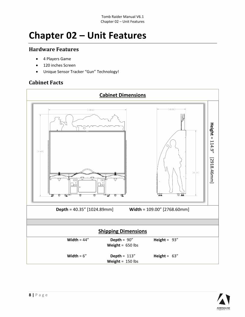
Cabinet Facts
Cabinet Dimensions
Heigh
t = 11
4.9
” [29
18
.46
mm
]
Depth = 40.35” [1024.89mm] Width = 109.00” [2768.60mm]
Shipping Dimensions
Width = 44” Depth = 90” Height = 93” Weight = 650 lbs
Width = 6” Depth = 113” Height = 63”
Weight = 150 lbs

Tomb Raider Manual V6.1 Chapter 03 – Unit Installation
9 | P a g e
Chapter 03 – Unit Installation
Parts included
1x Large bag bolts & washers (For Cabinet Assembly)
- 34x Allen Button Head Black Bolts #10-24 x 1½”
- 34x Black Washers #10
- 2x Allen Button Head Black Bolts ¼-20 x ¾”
- 2x Black Washers ¼”
- 15x Phillips Black Screws #8 x ¾”
- 4x Carriage Black Bolts #10-24 x 1½”
- 4x K-Lock Nuts #10-24 zinc
1x Small bag bolts & washers & Flat Bars (For Header Assembly)
- 2x metal square 2½” x 2½” x 5/8”
- 19x Phillips Black Screws #8 x ¾”
- 2x Metal Flat Bar zinc 5/8” x 2”
- 8x Screws zinc #6 x 3/8”
- 2x Metal Angle
1x Left Cabinet
1x Center Cabinet
1x Right Cabinet
1x Left Side Panel
1x Right Side Panel
1x “Lara” Header part
1x “Tomb Raider” Header part
1x “Mountain” Header part
1x Left tablet with splitter power cable
1x Right tablet
1x Large Metal Angle Plate
1x Small Metal Plate with Fold
1x Box with Screen
Tomb Raider Manual V6.1 Chapter 03 – Unit Installation
10 | P a g e
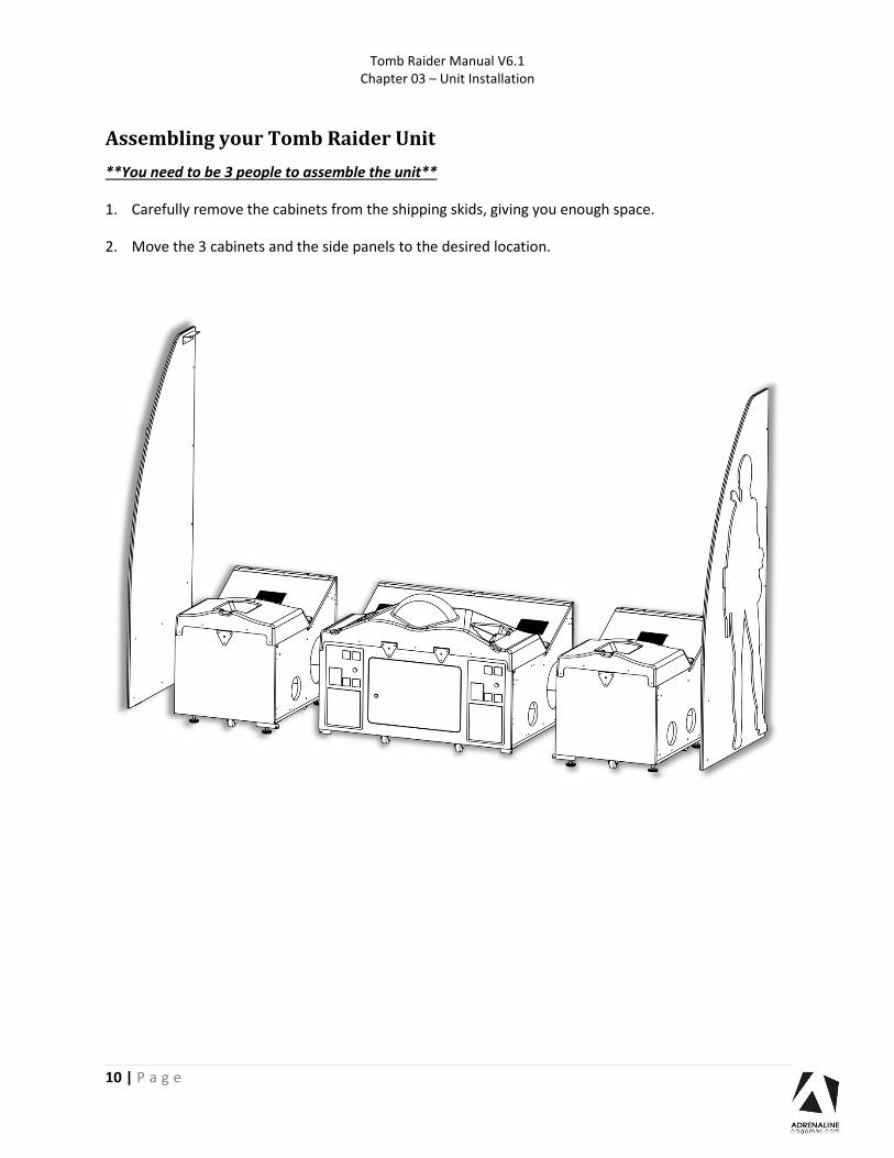
Assembling your Tomb Raider Unit
**You need to be 3 people to assemble the unit**
1. Carefully remove the cabinets from the shipping skids, giving you enough space.
2. Move the 3 cabinets and the side panels to the desired location.

Tomb Raider Manual V6.1 Chapter 03 – Unit Installation
11 | P a g e
Cabinet & Side Panels Assembly
3. Assemble the cabinet together using the provided 10X Bolts Allen button head #10-24 x 1-½” &
washers. 5x Bolts per sides.
The bolts need to be inserted from the center cabinet towards the exterior ones.
You will need to remove the back cabinet service doors to get the access.
You will also need to open the upper coin door from the center cabinet to install bolts there too.
Tomb Raider Manual V6.1 Chapter 03 – Unit Installation
12 | P a g e
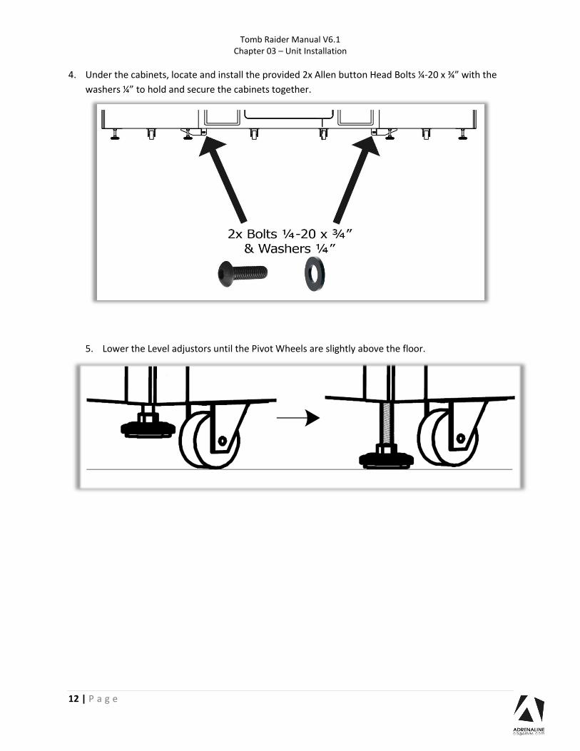
4. Under the cabinets, locate and install the provided 2x Allen button Head Bolts ¼-20 x ¾” with the
washers ¼” to hold and secure the cabinets together.
5. Lower the Level adjustors until the Pivot Wheels are slightly above the floor.

Tomb Raider Manual V6.1 Chapter 03 – Unit Installation
13 | P a g e
6. The illuminated “Lara Croft” is the exterior side of the unit.
-Take the power cable from the side panel and guide it through the hole on the side cabinet.
-Slowly get the side panel closer to the cabinet while watching to avoid squeezing the cable.
-When it’s close enough, align the side panel with the cabinet.

Tomb Raider Manual V6.1 Chapter 03 – Unit Installation
14 | P a g e
7. Install the side panel to the cabinet by using the Black Allen Button Head Bolts #10-24 x 1½” and
Black Washers #10. Each side panels needs 6 bolts.
8. Install the metal angle on each panel with Black Phillips Screws #8 x ¾”.

Tomb Raider Manual V6.1 Chapter 03 – Unit Installation
15 | P a g e
9. Connect the 5 harnesses between the edge cabinets to the center cabinet together.

Tomb Raider Manual V6.1 Chapter 03 – Unit Installation
16 | P a g e
You should be very careful when touching the screen material as it is relatively
easy to scratch.
If the screen is dusty, use a feather duster. If this is not enough use a damp
cloth and wipe carefully sideways following the direction of the lens structure.
If rubbing too hard, you risk damaging the screen material and making a
noticeable mark.
Screen Assembly
10. *3 people minimum required*
Align the bottom of the screen to the upper back edge of the cabinet.
Flip it between the side panels.

Tomb Raider Manual V6.1 Chapter 03 – Unit Installation
17 | P a g e
11. Using the #10-24 x 1½” Allen Head Buttons Bolts & Washers #10 (3 on each sides), affix the screen
to the side panels of the cabinet.

Tomb Raider Manual V6.1 Chapter 03 – Unit Installation
18 | P a g e
12. Secure the metal bottom plate of the screen to the cabinet by using the 7x black Philips screws #8 x
¾”.
13. The +12V Barrel Power Cable behind the cabinet will be for the header LEDs power. Leave it
attached for now we will use it later.

Tomb Raider Manual V6.1 Chapter 03 – Unit Installation
19 | P a g e
Header Assembly

Tomb Raider Manual V6.1 Chapter 03 – Unit Installation
20 | P a g e
14. Parts Needed: “Right Side” piece of wood, the large metal square, the small metal square,
2x Carriage Bolts #10-24 x 1½” and 2x K-Lock Nuts #10-24.
- Install the longer side of the larger square metal bracket on a flat surface, the smaller side will
be vertical and near you.
- Take the piece of wood that has the larger “groove” on top and install it on the left side of the
square bracket ass seen below.
- Take the smaller metal bracket square and align the holes with those on the piece of wood.
- Align & insert the carriage bolts towards you and secure it with the K-Nut.

Tomb Raider Manual V6.1 Chapter 03 – Unit Installation
21 | P a g e
15. Parts needed: “Left Side” Piece of wood, 2x Carriage Bolts #10-24 x 1½” and 2x K-Lock Nuts #10-24.
- Slide the 2nd piece of wood between the metal square brackets.
- Align and secure it with the bolts and nuts.
“Front view”
“Back View”

Tomb Raider Manual V6.1 Chapter 03 – Unit Installation
22 | P a g e
16. 2 ladders and minimum 2 people needed.
Go behind the unit, one person on each side.
Install the header platform assembly on the side panel’s brackets and the screen as followed.
The header assembly square metal bracket has to be behind the screen.
-Using 6x Bolts Allen Button Head #10-24 x 1½” affix the header to the top of the screen.
Tomb Raider Manual V6.1 Chapter 03 – Unit Installation
23 | P a g e
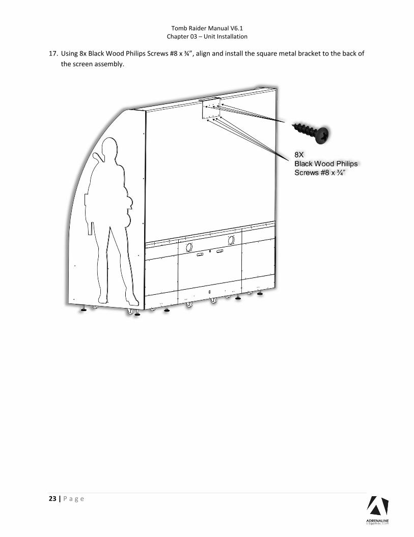
17. Using 8x Black Wood Philips Screws #8 x ¾”, align and install the square metal bracket to the back of
the screen assembly.

Tomb Raider Manual V6.1 Chapter 03 – Unit Installation
24 | P a g e
18. Using 4x Black Wood Philips Screws #8 x ¾”, secure the square metal brackets to the header
platform assembly.

Tomb Raider Manual V6.1 Chapter 03 – Unit Installation
25 | P a g e
19. Take the “Tomb Raider” Plexiglas part and remove the film protection.
- Install the small metal square 2½” x 2½” x 5/8” to the acrylic with 2x screws zinc #6 x 3/8”.
- Insert it in the groove as seen below.
- Using 2x Black Wood Philips Screws #8 x ¾”, secure the Plexiglas to the wood assembly through the
small metal square.

Tomb Raider Manual V6.1 Chapter 03 – Unit Installation
26 | P a g e
20. Take the “Lara” Plexiglas part and remove the film protection.
- Install the small metal square 2½” x 2½” x 5/8” to the acrylic with 2x screws zinc #6 x 3/8”.
- Insert it in the groove next to the “Tomb Raider” section as seen below.
- Using the Black Wood Philips Screws #8 x ¾”, secure the Plexiglas to the assembly through the
small square metal bracket 2½” x 2½” x 5/8”.

Tomb Raider Manual V6.1 Chapter 03 – Unit Installation
27 | P a g e
21. Install the Mountains cardboard into the groove as seen below.
22. Insert the metal flat bars through the holes of the cardboard and using the Black Wood Philips
Screws #8 x ¾” secure the cardboard to the assembly.

Tomb Raider Manual V6.1 Chapter 03 – Unit Installation
28 | P a g e
23. Connect the 12V Barrel connector with the one coming from the cabinet. Use tape to stick it behind
the screen assembly and avoiding a loose cable.

Tomb Raider Manual V6.1 Chapter 04 – Operator Menu
29 | P a g e
Chapter 04 – Operator Menu
Operator Menu
Access the Operator Menu by pressing the Operator button located inside the drawer on the I/O board
directly.
Oper: Open the Operator Menu
Up: Scroll Up & Increase Value
Down: Scroll Down & Decrease Value
Select Button: Select/Deselect
The following page contains details on each setting

Tomb Raider Manual V6.1 Chapter 04 – Operator Menu
30 | P a g e
Operator Menu Values What It Does Credits Per Game 1-20 Adjusts the number of credits required to play. “0” sets
the unit in free play mode
Game Audio Volume 0-20 Adjusts the in-game audio volume. “0” will mute the game
Attract Audio Volume 0-20 Adjusts the audio volume of the attract loop. “0” will mute the attract loop
Payment Type Credit / Card Changes the credit type. “Credits” = Coins and “Card” = Card Reader. This will change the in-game text
accordingly
Credit Sharing 1_2 / 3_4
On / Off Adjusts the credit sharing option between each player.(Off: Sharing Disabled // On: Sharing Enabled)
If you have Card Reader (4X) please use OFF
Gun Frequency 1-4 If you have 2 units close to each other select a different frequency. (Default: 2)
Gun P1 On / Off Gun Operating Mode (On: Working Off: Not Working)
Gun P2 On / Off Gun Operating Mode (On: Working Off: Not Working)
Gun P3 On / Off Gun Operating Mode (On: Working Off: Not Working)
Gun P4 On / Off Gun Operating Mode (On: Working Off: Not Working)
Gun Tool Calibration tool to test the gun’s response to the player’s movements
Aim Calibration Opens a calibration tool for each player’s target
Error Logs Displays the previous errors
Diagnostics Test for each gun’s triggers and vibration Test for each button
Clear Credits Resets the inserted credits to 0 if more than 40 credits are entered
Game Stats Shows the Stats Screen
Resume Game Exits the Operator Menu and returns to the game
Quit Game Exits the game and returns to the Windows desktop
Tomb Raider Manual V6.1 Chapter 05 – Service & repair
31 | P a g e
Chapter 05 – Service & Repair
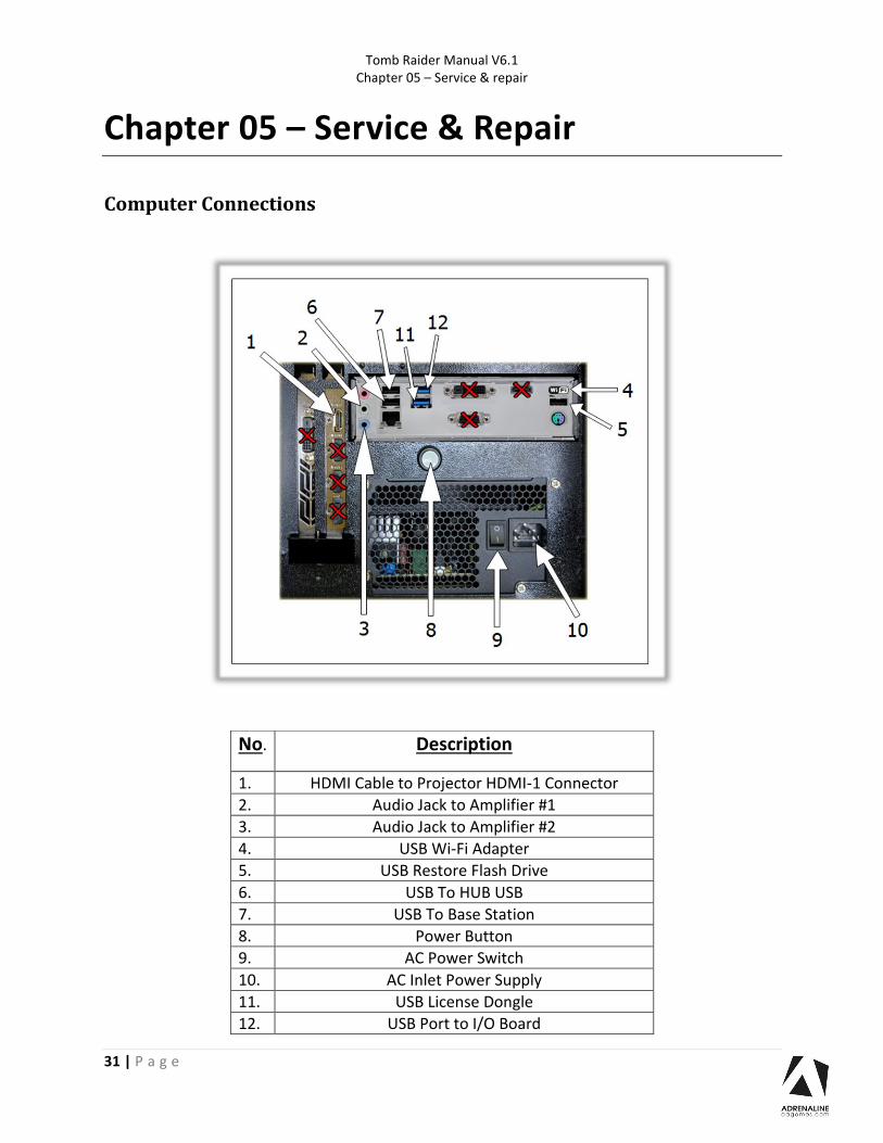
Computer Connections
No. Description
1. HDMI Cable to Projector HDMI-1 Connector
2. Audio Jack to Amplifier #1
3. Audio Jack to Amplifier #2
4. USB Wi-Fi Adapter
5. USB Restore Flash Drive
6. USB To HUB USB
7. USB To Base Station
8. Power Button
9. AC Power Switch
10. AC Inlet Power Supply
11. USB License Dongle
12. USB Port to I/O Board

Tomb Raider Manual V6.1 Chapter 05 – Service & repair
32 | P a g e
Projector Connections

Tomb Raider Manual V6.1 Chapter 05 – Service & repair
33 | P a g e
Projector Settings Recommended Projector Picture Settings
Here are new recommended settings to improve the screen display from the projector.
To adjust the projector settings, open the center cabinet service door and use the remote control.
There are 2 IR receivers on the projector, 1 on the back and 1 on the top.
-Press the Menu Key on the remote control.
From the main Picture screen, change the 3 following settings.
Brightness: 60
Contrast: 76
Gamma: 3

Tomb Raider Manual V6.1 Chapter 05 – Service & repair
34 | P a g e
To adjust the focus, use the Focus Adjustment Switch on the right of the projector.

Tomb Raider Manual V6.1 Chapter 05 – Service & repair
35 | P a g e
Gun Controller ID Remapping
Each gun controller has an ID # to be identified as Player 1 to Player 4. If a Stem Stick is replaced and/or
has a wrong ID, it needs to be remapped. If a gun controller is not detected in the game, first verify
within the Operator menu “Gun Tool” to see if the 4 guns are detected.
If a gun is missing verify with this tool and in need contact technical support team.
Instructions:
Quit the game on the Windows desktop.
On the Windows desktop you have an icon shortcut called “Magnetometer Calibration Compass”
(January-June 2018) or “Controller ID Calibration” (June 2018-…)
Double click on it to start the program.
You do not need to use the Calibration button anymore as this is now handled by the game itself. With
the updated version the Calibration button is removed.
When you pick up a Gun controller from its holster it should display which device has been picked up.
If you have 2x Stem Stick with the Same ID, you can find the one that needs to be remapped to its good
ID.

Tomb Raider Manual V6.1 Chapter 05 – Service & repair
36 | P a g e
To remap an ID, double click with the mouse to select the good Stem Stick ID.
Click in the “Change ID (1-4)” box with your mouse and enter the good ID number (1 to 4) that matches
the player position.
In this example, the Device B is wrongly set to ID#2, so we enter the number “1” and click on Set to
change it to Player 1.
Tomb Raider Manual V6.1 Chapter 05 – Service & repair
37 | P a g e
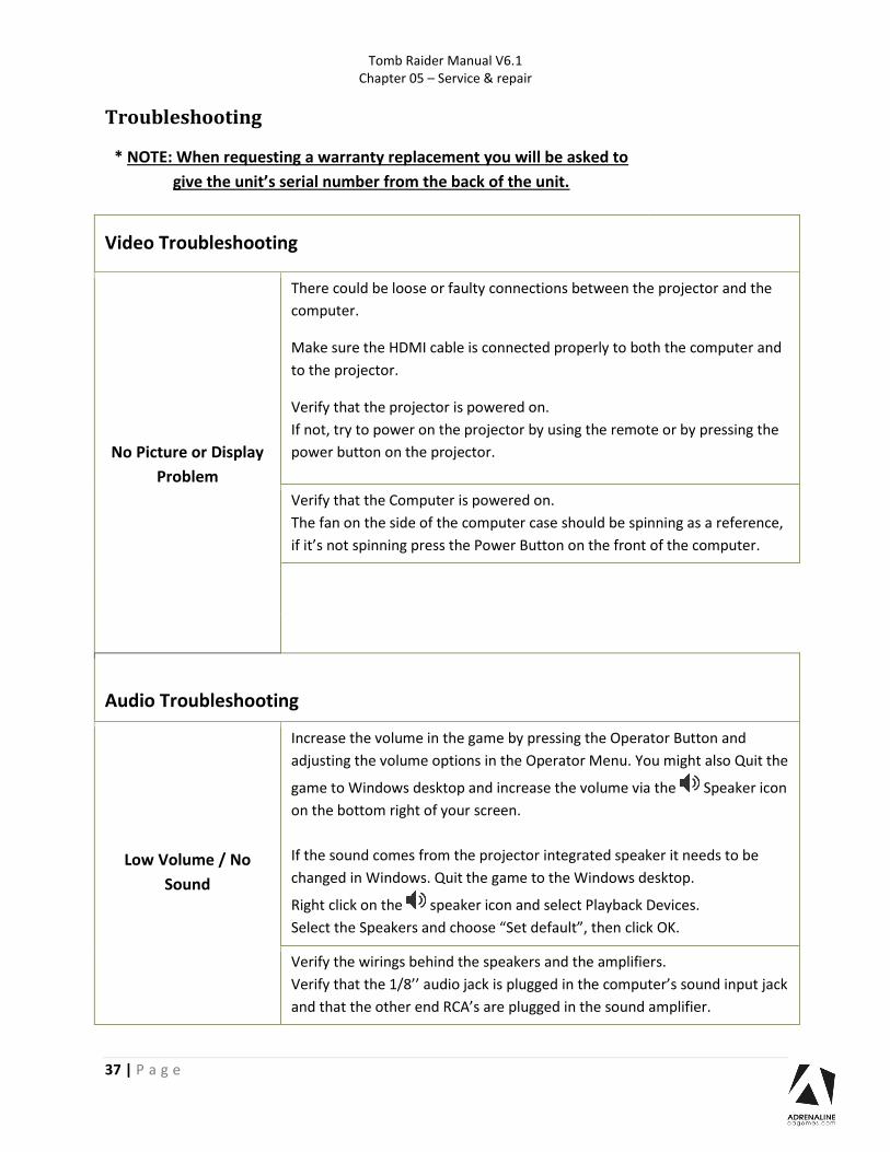
Troubleshooting
* NOTE: When requesting a warranty replacement you will be asked to
give the unit’s serial number from the back of the unit.
Video Troubleshooting
No Picture or Display
Problem
There could be loose or faulty connections between the projector and the
computer.
Make sure the HDMI cable is connected properly to both the computer and
to the projector.
Verify that the projector is powered on.
If not, try to power on the projector by using the remote or by pressing the
power button on the projector.
Verify that the Computer is powered on.
The fan on the side of the computer case should be spinning as a reference,
if it’s not spinning press the Power Button on the front of the computer.
Audio Troubleshooting
Low Volume / No
Sound
Increase the volume in the game by pressing the Operator Button and
adjusting the volume options in the Operator Menu. You might also Quit the
game to Windows desktop and increase the volume via the Speaker icon
on the bottom right of your screen.
If the sound comes from the projector integrated speaker it needs to be
changed in Windows. Quit the game to the Windows desktop.
Right click on the speaker icon and select Playback Devices.
Select the Speakers and choose “Set default”, then click OK.
Verify the wirings behind the speakers and the amplifiers.
Verify that the 1/8’’ audio jack is plugged in the computer’s sound input jack
and that the other end RCA’s are plugged in the sound amplifier.
Tomb Raider Manual V6.1 Chapter 05 – Service & repair
38 | P a g e
Wireless Internet Configuration
Your network can be configured via Ethernet cable or Wireless.
If you have an Ethernet cable available to be plugged in, insert it into the motherboard LAN
RJ45 connector.
If not, here’s how to configure your wireless network with your own existing Wi-Fi network.
-Start the unit.
-There will be Adrenaline Amusements wallpaper with a 150 seconds delay before the attract
mode shows up. It gives enough time for a wireless network to connect.
(This delay will be present on each reboot if you don’t connect your unit to the Internet)*.
-Open the service door and press the Operator button.
-Choose Exit/Quit to Windows.
-Connect the provided USB hub and into it the USB keyboard and mouse.
- Open Connect to a Network by clicking the network icon ( ) in the lower right corner of the screen.
-In the list of networks, click the network you want to connect to and click connect.
-Enter your security key.
-Once connected, double-click the GameLauncher shortcut on the desktop.
Having your unit connected to the Internet includes free software live update!
*If you do not connect your unit to the Internet, you can double-click the Disable_Network
shortcut on the Windows desktop to bypass the 150seconds Internet lookup delay.
Tomb Raider Manual V6.1 Chapter 05 – Service & repair
39 | P a g e
Operator Settings keeps resetting trouble
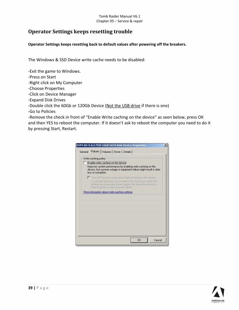
Operator Settings keeps resetting back to default values after powering off the breakers.
The Windows & SSD Device write cache needs to be disabled: -Exit the game to Windows. -Press on Start -Right click on My Computer -Choose Properties -Click on Device Manager -Expand Disk Drives -Double click the 60Gb or 120Gb Device (Not the USB drive if there is one) -Go to Policies -Remove the check in front of “Enable Write caching on the device” as seen below, press OK and then YES to reboot the computer. If it doesn’t ask to reboot the computer you need to do it by pressing Start, Restart.

Tomb Raider Manual V6.1 Chapter 05 – Service & repair
40 | P a g e
Computer not powering at boot If your computer is not powering on by itself at boot verify the Bios Setting.
-Power off the unit.
-Plug a USB keyboard.
-Power on the unit, press and hold “DELETE” on the keyboard until you see the Bios screen.

Tomb Raider Manual V6.1 Chapter 06 – Parts
41 | P a g e
Chapter 06 - Parts
Cabinet Parts
Ref Part Description Part # 1 Complete 120'' Laminated Screen Including Foam, Box, Metal Brackets and
Corner Protection RHW-10-0005-KIT
2 Left Side Panel, Printed melamine with LEDs and Lara Croft Plexiglass, TR 120'' TR-09-0004-L-KIT
3 Lara Croft Plexiglass TR-09-0004-LARA
4 Thermoformed Left or Right Console TR 120'' TR-07-0002
5 Door Assembly With 2 Upper Mech Holder, 1 Validator Cut Out, Blank Bottom Door
ADR-40-3000-06LKA
6 Thermoformed Center Console TR 120'' TR-07-0001
7 Leg Leveler 1/2"-13 x 4" Thread, 2-3/8" Base Diameter INV-62805K-39
8 General Duty Rubber Caster, 2-1/2'' INV-F25083
9 Speaker 4'' ADR-50-9986-00
10 Right Side Panel, Printed melamine with LEDs and Lara Croft Plexiglass, TR 120'' TR-09-0004-R-KIT
Tomb Raider Manual V6.1 Chapter 06 – Parts
42 | P a g e
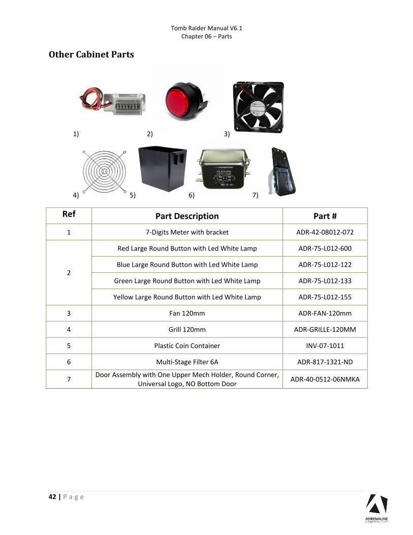
Other Cabinet Parts
1) 2) 3)
4) 5) 6) 7)
Ref Part Description Part #
1 7-Digits Meter with bracket ADR-42-08012-072
2
Red Large Round Button with Led White Lamp ADR-75-L012-600
Blue Large Round Button with Led White Lamp ADR-75-L012-122
Green Large Round Button with Led White Lamp ADR-75-L012-133
Yellow Large Round Button with Led White Lamp ADR-75-L012-155
3 Fan 120mm ADR-FAN-120mm
4 Grill 120mm ADR-GRILLE-120MM
5 Plastic Coin Container INV-07-1011
6 Multi-Stage Filter 6A ADR-817-1321-ND
7 Door Assembly with One Upper Mech Holder, Round Corner,
Universal Logo, NO Bottom Door ADR-40-0512-06NMKA

Tomb Raider Manual V6.1 Chapter 06 – Parts
43 | P a g e
Wood module parts
Ref Part Description Part #
2 TR 120’’-Printed Melamine -02 TR-09-0006-ITEM-2
3
TR 120’’-Printed Melamine -03 For Coin Door ADR-40-3000-06LKA
TR-09-0005-01-ITEM-3A
TR 120’’-Printed Melamine -03 For Coin Door ADR-40-0512-06-NMKA
TR-09-0005-01-ITEM-3B
4 Front Access Door TR 120'' TR-09-0005-01-ITEM-4
5 TR 120’’-Printed Melamine -05 TR-09-0006-ITEM-5
6 TR 120’’-Printed Melamine -06 TR-09-0006-ITEM-6
8 120'' Melamine- 08 SHT-02-6002-08
9 120'' Melamine- 09 SHT-02-6002-09
10 120'' Melamine- 10 SHT-02-6002-10
11 120'' Melamine- 11 SHT-02-6002-11
12 Rear Access Door Cabinet 120'' SHT-02-6002-12
13 120'' Melamine- 13 SHT-02-6002-13
14 Glasses for Projection, 4mm RHW-10-0003

Tomb Raider Manual V6.1 Chapter 06 – Parts
44 | P a g e
Screen Assembly
Ref Part Description Part Number
1 Top Frame Screen 120'' Bracket SHT-01-8002
2 Side Frame Screen 120'' Bracket SHT-01-8001
3 Replacement Back of 120'' Screen RHW-10-0005-BACK
4 Bottom Frame Screen 120'' Bracket SHT-01-8010
5 Repair screen 120 inches for Tomb Raider REPAIR-KIT-SCREEN120

Tomb Raider Manual V6.1 Chapter 06 – Parts
45 | P a g e
Computer & Electronics
Ref Part Description Part Number
1 Power Bar IEC5GLM INV-05-1242
2 I/O Board – 4 Players/Motors – Ver. 5.0 ADR-04-1003-RHW/TR
3 Sound Amplifier 2X15W INV-14-0005
4 +12V / 320W Power Supply INV-05-1248
5 Switching Power Supply, 12 V, 5A, 2.1mm x 5.5mm Plug INV-14-0006
6 PC Box for Tomb Raider with Fujitsu H310 And GTX1650 ADR-11-1017-03-TR
7 7-Port USB, 2.0 Hub, Type A Female USB INV-11-1021
9 Hard Drive for Tomb Raider for H110 INV-11-1027-TR-H110
Hard Drive for Tomb Raider for Fujitsu H310 INV-11-1027-TR-H310
10 Restore USB Key for Tomb Raider for H110 ADR-11-2014-TR-H110
Restore USB Key Tomb Raider for Fujitsu H310 ADR-11-2014-TR-H310
7)
8)
9)

Tomb Raider Manual V6.1 Chapter 06 – Parts
46 | P a g e
Game Controllers
Part Description Part Number
Game Controller for Tomb Raider 120'' Player 1 TR-05-0011-1
Game Controller for Tomb Raider 120'' Player 2 TR-05-0011-2
Game Controller for Tomb Raider 120'' Player 3 TR-05-0011-3
Game Controller for Tomb Raider 120'' Player 4 TR-05-0011-4

Tomb Raider Manual V6.1 Chapter 06 – Parts
47 | P a g e
Ref Part Description Part Number
1 Compression Spring, 5/8’’ I.D. X 1-5/8’’, 4lbs TR-05-0001
2 Stem Stick Position Tracker Board, Version 3, With Resin, Coil 8mm and Licence INV-04-1302-03
3 Black Trigger for Game Controller ADR-96-2515-06
4 Kit Including Vibration Motor and Snubber for Game Controller INV-15-0006-KIT
5 Spring for Trigger Return ADR-96-0005-00
6 Hex Drive Rounded Head Screw, Stainless Steel, M3 x 0.5 mm, 4 mm Long MS-HRO-ZS-M3X0.5MMX4MM
7 Trigger Switch for Game Controller ADR-95-4142-10
8 Left Handle Game Controller, Tomb Raider
Right Handle Game Controller, Tomb Raider TR-05-0002 TR-05-0003
9 Hose with Switches and Handle For Tomb Raider 120’’ 30SH-TR-KIT-H
10 Rounded Head Screws, Torx, Zinc-Plated Steel, #4-40 x 3/8" Long MS-TRO-ZS-N4-40X3/8
Nylon-Insert Locknut, Zinc-Plated Steel, 4-40 LN-ZS-4-40
11 Left Slide Game Controller, Tomb Raider
Right Slide Game Controller, Tomb Raider TR-05-0005 TR-05-0006
12 Rounded Head Screw, Torx, Zinc Plated Steel, #4-40 x 1/2'' Long MS-TRO-ZS-N4-40x1/2

Tomb Raider Manual V6.1 Chapter 06 – Parts
48 | P a g e
Other Electronics Parts
1) 2) 3) 4) 5) 6)
Hardware Kit Complete Hardware Kit for Tomb Raider 120’’ TR-120-HARDWARE
1) 2) 3) 4) 5) 6)
7) 8) 9) 10)
Ref Part Description Part Number 1 Round White Coil, 90mm INV-05-1246
2 Stem Stick Base Board with Licence AND Program INV-04-1301-01-PROG
3 Switching Power Supply, 15 V, 2.67A, 2.5 x 5.5mm Plug INV-05-1245
4 Projector Ultra Short Throw RHW-10-0001
5 Dongle Red, Tomb Raider INV-11-1002-01
6 Remote for Projector RHW-10-0001 RHW-10-0001-Remote
Ref Part Description Part Number Quantity
1 Button Head 10-24 x 1½ Bolts MS-PP-BS-10-24X1-1/2 34
2 Button Head ¼-20 x ¾ Bolts HS-HH-Z-1/4-20X3/4 2
3 Carriage 10-24 x 1½ Bolts CB-CRO-ZS-10-24x1-1/2 4
4 Philipps #8 x ¾ Black Screws PS-PP-BS-N08X3/4 34
5 #10 Flat Washers FW-S-N10 34
6 ¼ Flat Washers FW-Z-1/4 2
7 10-24 K-Nut LN-ZS-10-24 4
8 Pan Head #6 x 3/8'' Screws WS-PP-ZS-N6X3/8 8
9 5/8 x 2’’ Mending Plates CONS-52-0011 2
10 2½ x 2½ Square Brackets SB-2-1/2X2-1/2 2

Tomb Raider Manual V6.1 Chapter 06 – Parts
49 | P a g e
Header & LEDs
1) 2) 3)
4)
5) 6) 7)
Ref Part Description Part Number
1 Kit for Acrylic Lara Header, Tomb Raider 120'' TR-09-0001-KIT
2 Acrylic ''Tomb Raider'' Header, Tomb Raider 120'' TR-09-0002-KIT
3 Acrylic Mountain Header with LEDs, Tomb Raider 120'' TR-09-0003-KIT
4 Header Base Tomb Raider 120'' TR-09-0007
5 Side Top Header Bracket for Tomb Raider 120’’ TOMB-01-1004
6 Top Union Header Bracket for Tomb Raider 120’’ TOMB-01-1003
7 Bottom Union Header Bracket for Tomb Raider 120’’ TOMB-01-1002

Tomb Raider Manual V6.1 Chapter 06 – Parts
50 | P a g e
Cabling
Part Description Part Number HDMI Cable, 3’ INV-HDMI-140-03UT
USB “AB” cable, 3’ INV-USB-AB1-03
USB A Male to Mini-B 5-pins male, 6’ INV-USB-AM51-06
Extension USB A Male to USB A Female, 6’ INV-USB-AA3-06BK
Extension USB A Male to USB A Female, 3’ INV-USB-AA3-03
Audio Cable 3.5mm Male To 2x RCA Male, 6’ INV-35mm-RCAE-06
Power Cord IEC-C13 to IEC-C14, 18AWG, 2’ INV-PW-100-02
Power Cord IEC-C13 to IEC-C14, 18AWG, 3’ INV-PW-100-03
Power Cord IEC-C14 to IEC-C7, 18AWG, 3’ INV-PW-117-03
Splitter Cable Barrel connector 2.1mm Female to 4x 2.1mm Male INV-CN-DCF-4M
Straight Barrel Power Cable 2.1mm, 3’ ADR-CP-2216-ND
Splitter Cable Barrel Connector, 2.1mm Female to 2 x 2.1mm Male, 300mm TF-05-1223
Power Cable Straight Barrel 2.1mm, 3’ ADR-CP-2216-ND
USB Cable Male to Mini-B, 6’ INV-USB-AM51-06
Power Cord Set
Image Region Part Number
Canada, United States of America, Mexico INV-PW-105C-06
Europe INV-PW-170-3M
United Kingdom, United Arab Emirates, Saudi Arabia INV-PW-175-3M
India INV-PW-618-2M
Australia, Argentina INV-PW-665-2M
Tomb Raider Manual V6.1 Chapter 06 – Parts
51 | P a g e
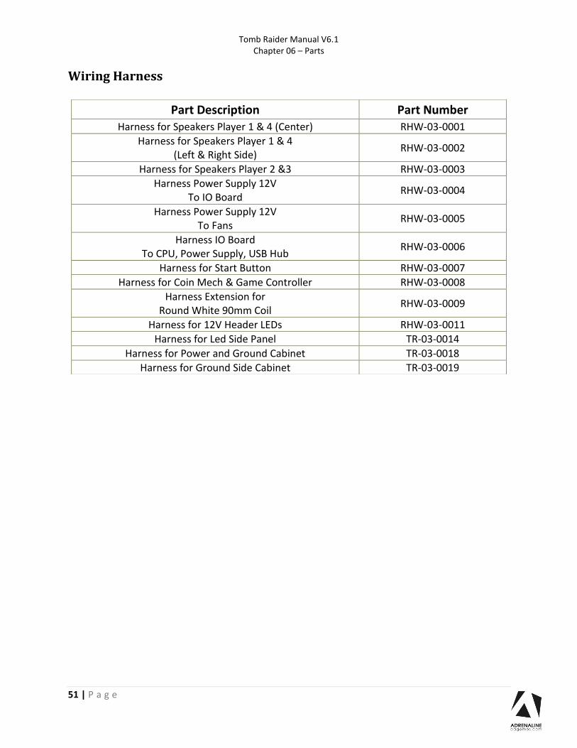
Wiring Harness
Part Description Part Number Harness for Speakers Player 1 & 4 (Center) RHW-03-0001
Harness for Speakers Player 1 & 4 (Left & Right Side)
RHW-03-0002
Harness for Speakers Player 2 &3 RHW-03-0003
Harness Power Supply 12V To IO Board
RHW-03-0004
Harness Power Supply 12V To Fans
RHW-03-0005
Harness IO Board To CPU, Power Supply, USB Hub
RHW-03-0006
Harness for Start Button RHW-03-0007
Harness for Coin Mech & Game Controller RHW-03-0008
Harness Extension for Round White 90mm Coil
RHW-03-0009
Harness for 12V Header LEDs RHW-03-0011
Harness for Led Side Panel TR-03-0014
Harness for Power and Ground Cabinet TR-03-0018
Harness for Ground Side Cabinet TR-03-0019

Tomb Raider Manual V6.1 Chapter 07 – Diagrams & Schematics
52 | P a g e
Chapter 07 – Diagrams & Schematics
I/0 Board ADR-04-1003

Tomb Raider Manual V6.1 Chapter 07 – Diagrams & Schematics
53 | P a g e
J1 J2 J3 J4 No Use
No Use No Use No Use
J5 J6 J7 J8 MOTOR 5V 1. (Red) +5V
2. (Black) GND 3. (Red) +5V
4. (Black) GND 5. (Red) +5V
6. (Black) GND 7. (Red) +5V
8. (Black) GND
No Use
No Use
No Use
J9 J10 J11 J12 No Use
Player 1- Buttons
1. (Yellow) +12V 2. (Green) OUT 3. (Brown) GND 4. (Orange) IN1 5. (Blue) GND 6. (White) IN2
Player 2- Buttons 1. (Yellow) +12V 2. (Green) OUT 3. (Brown) GND 4. (Orange) IN1 5. (Blue) GND 6. (White) IN2
Player 3- Buttons 1. (Yellow) +12V 2. (Green) OUT 3. (Brown) GND 4. (Orange) IN1 5. (Blue) GND 6. (White) IN2
J13 J14 J15 J16 Player 4- Buttons
1. (Yellow) +12V 2. (Green) OUT 3. (Brown) GND 4. (Orange) IN1 5. (Blue) GND 6. (White) IN2
12V Input DC
5V/12V Input DC
USB To Computer
J17 J18 J19 J20 Coin Door Player-1
1. (White) +12V 2. (Black) GND
3. (Red) IN1 4. Not Connected
5. (Blue) GND 6. (Orange) OUT1 7. (Purple) OUT2 8. (Green) +12V
Coin Door Player-2 1. Not Connected 2. Not Connected
3. (Brown) IN1 4. Not Connected 5. Not Connected 6. Not Connected 7. (Purple) OUT2 8. Not Connected
Coin Door Player-3 1. (White) +12V 2. (Black) GND
3. (Red) IN1 4. Not Connected
5. (Blue) GND 6. (Orange) OUT1 7. (Purple) OUT2 8. (Green) +12V
Coin Door Player-4 1. Not Connected 2. Not Connected
3. (Brown) IN1 4. Not Connected 5. Not Connected 6. Not Connected 7. (Purple) OUT2 8. Not Connected

Tomb Raider Manual V6.1 Chapter 07 – Diagrams & Schematics
54 | P a g e
I/O Board - Wiring

Tomb Raider Manual V6.1 Chapter 07 – Diagrams & Schematics
55 | P a g e

Tomb Raider Manual V6.1 Chapter 07 – Diagrams & Schematics
56 | P a g e

Tomb Raider Manual V6.1 Chapter 07 – Diagrams & Schematics
57 | P a g e

Tomb Raider Manual V6.1 Chapter 07 – Diagrams & Schematics
58 | P a g e

Tomb Raider Manual V6.1 Chapter 07 – Diagrams & Schematics
59 | P a g e
Speakers Wiring Colors

Tomb Raider Manual V6.1 Chapter 07 – Diagrams & Schematics
60 | P a g e
Power Distribution Schematics

Tomb Raider Manual V6.1 Chapter 07 – Diagrams & Schematics
61 | P a g e

Tomb Raider Manual V6.1 Chapter 08 – Software Recovery
62 | P a g e
Chapter 08 – Software Recovery
If your unit software needs to be restored please follow those instructions.
- Connect a USB keyboard to the motherboard.
- Connect the provided USB Recovery flash disk is in a Black USB port.
- Power on the unit and press F8 on the keyboard to display the boot menu.
- Choose the UEFI: USB device ~16GB
The process takes 25-30 minutes and the unit will reboot back in the game at the end. The
Wireless credentials will need to be re-entered and Operator settings will be back at the default
ones.

Tomb Raider Manual V6.1 Chapter 09 – Card Reader
63 | P a g e
Chapter 09 – Card Reader
Configure your Operator settings as seen in Chapter 04.
Embed System
If you are using an Embed system, you need to connect your harnesses to Adrenaline Amusements I/O
board & harnesses. You should refer to the Embed instructions manual for wiring pin-out.
The typical Embed settings are Standard except:
-Ticket Mech Type: Dumb DC
-Drive Polarity: Positive
-Notch Polarity: Negative
-Game ticket notch width = 6 (60ms)
-Game ticket notch spacing = 24 (240ms)
-Game Drive Threshold = 15 (1.5V or 1500mV)
-Drive Debounce = 40ms

64 | P a g e
Limited Warranty Policies
Customers must provide the unit serial number when claiming any warranty request.
Adrenaline Amusements (AAGames) warrants this Arcade unit (Including
accessories) against defects in material or workmanship as follows:
This unit has 1 year warranty against defective on all electronic parts from
date of delivery. The projector has an extended warranty of 3 years from
date of delivery.
Other than abuse or improper servicing, Adrenaline Amusements covers at
no charge the replacement parts including standard shipping.
We offer an advanced replacement program and the customers have 30
days from delivery date to return back the defective equipment at their fees
or they will be charged automatically for the replacement parts.
Improper servicing or abuse will VOID existing warranties.
All warranty request needs to be validated with our technical support
department.
After the 1 year warranty, Adrenaline Amusements offers repairs & sales
services options. Please contact the technical support department for
information.
Adrenaline Amusements
2273 Antonio-Héroux street
Terrebonne, QC
Canada
J6X 4R3
+1.450.824.1671


