Toolpath generation for layer manufacturing of fractal objects W.K. Chiu, Y.C. Yeung and K.M. Yu Department of Industrial and Systems Engineering, The Hong Kong Polytechnic University, Kowloon, People’s Republic of China Abstract Purpose – Fractal geometry can be used to model natural objects which cannot be easily represented by the euclidean geometry. However, contemporary computer-aided design (CAD) and computer-aided manufacturing (CAM) systems cannot be used to model a fractal object efficiently. In a general layer manufacturing (LM) workflow, a model described by the euclidean geometry is required in order to generate the necessary toolpath information. So this workflow cannot be applied for a fractal object. In this paper, to realize the fabrication of a fractal represented object by the LM technology, a methodology is proposed. Design/methodology/approach – In the proposed methodology, a slab grid is generated in each layer of the object and it consists of a number of pixels. The interior property (corresponding to the fractal object) of each pixel in the slab grid is checked so that slab models of the fractal are created. The boundary of each slab is traced and refined so that the toolpath of the object can be generated from these boundaries. Findings – Applying the proposed methodology, the LM toolpath information can be extracted from the mathematical model of the fractal and the tessellating or slicing processes are not needed to be performed. The problem of representing a fractal in a CAD platform can be eliminated. Research limitations/implications – The proposed methodology can be applied to iterative function system (IFS) or complex fractal. However, for some fractals constructed from more than one kind of fractal objects, such as multi-IFS fractals, the methodology must be further developed. Originality/value – The proposed methodology is a novel development for realizing the fabrication of fractal objects by the LM technology. Keywords Computer aided design, Computational geometry, Modelling Paper type Research paper 1. Introduction 1.1 Contemporary CAD/CAM Contemporary computer-aided design (CAD)/computer- aided manufacturing (CAM) theories and systems are well developed only for euclidean analytical objects and free- form objects (e.g. car bodies). Euclidean geometry (Figure 1) is comprised of lines, planes, rectangular volumes, etc. Some of the free-form curve representations used in contemporary CAD systems are Bezier, B-spline and the most general non-uniform rational B-spline (NURBS) curves. They present usually smoother shapes and are indicated for modeling organic shapes. Euclidean geometries are defined by algebraic formula, for example, x 2 þ y 2 ¼ r 2 is used to define a sphere. These elements can be classified as belonging to an integer dimension either one, two, or three. This concept of dimension can be described both intuitively and mathematically (Mortenson, 1995). Currently, most of the commercial CAD systems are either based on solid or surface modeling systems. Two common choices are usually used to represent a 3D object, a boundary based representation called boundary representation (B-Rep), and a volume-based representation, called constructive solid geometry (CSG). Solid modeling, usually encountered as CSG, is used to create complex solid models by combining simple solid primitive. CSG has its mathematical foundations in topology, algebraic geometry, and Boolean algebra. However, depending on a particular CAD modeling system being used, the modeling capability is limited by the availability of solid primitives. Hence, B-Rep distinguishes vertices, edges, and polygons, but no explicit relations are maintained between them. However, there are still many types of objects, such as flexible objects with deformable geometry and non-euclidean geometrical objects, that cannot be represented efficiently by the current available CAD representation schemes. For some fragmented and self-similar aesthetic products, such as the example shown in Figure 2, geometric tools other than the euclidean one are required. In this case, the fractal geometric theory can be used to mathematically define these types of products. However, these fractal objects are usually used as textures in the field of computer graphics and can only be visualized via the computer graphics systems. In these cases, the fractals are stored as an array of pixel elements. At present, no representation schemes are available for storing the geometrical and topological information of a fractal model and processing of this fractal object is thus difficult. The current issue and full text archive of this journal is available at www.emeraldinsight.com/1355-2546.htm Rapid Prototyping Journal 12/4 (2006) 214–221 q Emerald Group Publishing Limited [ISSN 1355-2546] [DOI 10.1108/13552540610682723] The work described in this paper was substantially supported by a grant from the Research Grants Council of the Hong Kong Special Administrative Region (Project No. PolyU 5193/02E). Received: 26 October 2005 Revised: 17 January 2006 Accepted: 29 March 2006 214
Transcript
Toolpath generation for layer manufacturingof fractal objectsW.K. Chiu, Y.C. Yeung and K.M. Yu
Department of Industrial and Systems Engineering, The Hong Kong Polytechnic University, Kowloon, People’s Republic of China
AbstractPurpose – Fractal geometry can be used to model natural objects which cannot be easily represented by the euclidean geometry. However,contemporary computer-aided design (CAD) and computer-aided manufacturing (CAM) systems cannot be used to model a fractal object efficiently. In ageneral layer manufacturing (LM) workflow, a model described by the euclidean geometry is required in order to generate the necessary toolpathinformation. So this workflow cannot be applied for a fractal object. In this paper, to realize the fabrication of a fractal represented object by the LMtechnology, a methodology is proposed.Design/methodology/approach – In the proposed methodology, a slab grid is generated in each layer of the object and it consists of a number ofpixels. The interior property (corresponding to the fractal object) of each pixel in the slab grid is checked so that slab models of the fractal are created.The boundary of each slab is traced and refined so that the toolpath of the object can be generated from these boundaries.Findings – Applying the proposed methodology, the LM toolpath information can be extracted from the mathematical model of the fractal and thetessellating or slicing processes are not needed to be performed. The problem of representing a fractal in a CAD platform can be eliminated.Research limitations/implications – The proposed methodology can be applied to iterative function system (IFS) or complex fractal. However, forsome fractals constructed from more than one kind of fractal objects, such as multi-IFS fractals, the methodology must be further developed.Originality/value – The proposed methodology is a novel development for realizing the fabrication of fractal objects by the LM technology.
Contemporary computer-aided design (CAD)/computer-aided manufacturing (CAM) theories and systems are welldeveloped only for euclidean analytical objects and free-form objects (e.g. car bodies). Euclidean geometry(Figure 1) is comprised of lines, planes, rectangularvolumes, etc. Some of the free-form curve representationsused in contemporary CAD systems are Bezier, B-splineand the most general non-uniform rational B-spline(NURBS) curves. They present usually smoother shapesand are indicated for modeling organic shapes. Euclideangeometries are defined by algebraic formula, for example,x2 þ y2 ¼ r2 is used to define a sphere. These elements canbe classified as belonging to an integer dimension eitherone, two, or three. This concept of dimension can bedescribed both intuitively and mathematically (Mortenson,1995).Currently, most of the commercial CAD systems are either
based on solid or surface modeling systems. Two commonchoices are usually used to represent a 3D object, a boundarybased representation called boundary representation (B-Rep),and a volume-based representation, called constructive solid
geometry (CSG). Solid modeling, usually encountered as
CSG, is used to create complex solid models by combining
simple solid primitive. CSG has its mathematical foundations
in topology, algebraic geometry, and Boolean algebra.
However, depending on a particular CAD modeling system
being used, the modeling capability is limited by the
availability of solid primitives. Hence, B-Rep distinguishes
vertices, edges, and polygons, but no explicit relations are
maintained between them.However, there are still many types of objects, such as
flexible objects with deformable geometry and non-euclidean
geometrical objects, that cannot be represented efficiently by
the current available CAD representation schemes. For some
fragmented and self-similar aesthetic products, such as the
example shown in Figure 2, geometric tools other than the
euclidean one are required. In this case, the fractal geometric
theory can be used to mathematically define these types of
products. However, these fractal objects are usually used as
textures in the field of computer graphics and can only be
visualized via the computer graphics systems. In these cases,
the fractals are stored as an array of pixel elements. At
present, no representation schemes are available for storing
the geometrical and topological information of a fractal model
and processing of this fractal object is thus difficult.The current issue and full text archive of this journal is available at
www.emeraldinsight.com/1355-2546.htm
Rapid Prototyping Journal
12/4 (2006) 214–221
q Emerald Group Publishing Limited [ISSN 1355-2546]
[DOI 10.1108/13552540610682723]
The work described in this paper was substantially supported by a grantfrom the Research Grants Council of the Hong Kong SpecialAdministrative Region (Project No. PolyU 5193/02E).
Received: 26 October 2005Revised: 17 January 2006Accepted: 29 March 2006
The term “fractal” was introduced for characterizing spatial
or temporal phenomena that are continuous but not
differentiable (Mandelbrot, 1975). Fractal is defined as a
rough or fragmented geometric shape that can be sub-divided
into parts, each of which is (at least approximately) a reduced-
size copy of the whole. Mathematically, a fractal is defined as
a set of points whose fractal dimension exceeds its topological
dimension (Mandelbrot, 1983). In general, the dimension of
a fractal is typically a non-integer or a fraction, meaning its
dimension is not a whole number and its formation is by an
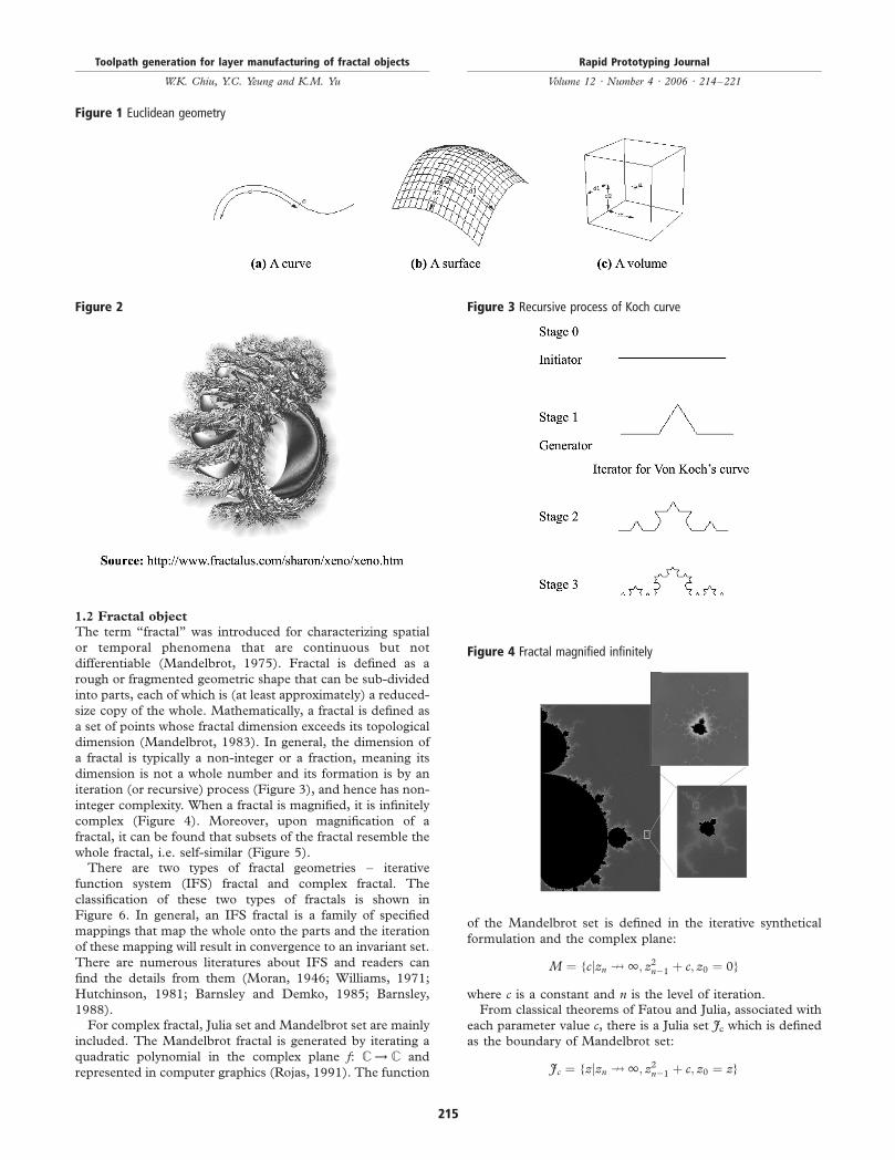
iteration (or recursive) process (Figure 3), and hence has non-
integer complexity. When a fractal is magnified, it is infinitely
complex (Figure 4). Moreover, upon magnification of a
fractal, it can be found that subsets of the fractal resemble the
whole fractal, i.e. self-similar (Figure 5).There are two types of fractal geometries – iterative
function system (IFS) fractal and complex fractal. The
classification of these two types of fractals is shown in
Figure 6. In general, an IFS fractal is a family of specified
mappings that map the whole onto the parts and the iteration
of these mapping will result in convergence to an invariant set.
There are numerous literatures about IFS and readers can
find the details from them (Moran, 1946; Williams, 1971;
Hutchinson, 1981; Barnsley and Demko, 1985; Barnsley,
1988).For complex fractal, Julia set and Mandelbrot set are mainly
included. The Mandelbrot fractal is generated by iterating a
quadratic polynomial in the complex plane f: C ! C and
represented in computer graphics (Rojas, 1991). The function
of the Mandelbrot set is defined in the iterative synthetical
formulation and the complex plane:
M ¼ {cjzn K 1; z2n21 þ c; z0 ¼ 0}
where c is a constant and n is the level of iteration.From classical theorems of Fatou and Julia, associated with
each parameter value c, there is a Julia set Jc which is defined
as the boundary of Mandelbrot set:
Jc ¼ {zjzn K 1; z2n21 þ c; z0 ¼ z}
Figure 1 Euclidean geometry
Figure 2 Figure 3 Recursive process of Koch curve
Figure 4 Fractal magnified infinitely
Toolpath generation for layer manufacturing of fractal objects
W.K. Chiu, Y.C. Yeung and K.M. Yu
Rapid Prototyping Journal
Volume 12 · Number 4 · 2006 · 214–221
215
where Jc of function fc: z ! z2 is connected if c [ M, Mconsists of all complex numbers c for which the sequence f(z),f( f(z)), f( f( f(z))), f( f( f( f(z)))), . . . remains bounded and doesnot diverge to infinity. In complex fractal, Mandelbrot set
includes the family of Julia set including connected sets(Fatou set) and Cantor sets (Fatou dust). Some special casesfor Mandelbrot set are shown in Figure 7. The details ofcomplex fractal can be found in different literatures (Branner,
1989; Peitgen and Richter, 1986; Falconer, 2003; Peitgenet al., 1991).
1.3 Prototype making by layer manufacturing
technology
When a physical prototype has to be fabricated, geometricaldata of the object must be obtained and input to the
corresponding prototype-making process, such as the layermanufacturing (LM) technology. To obtain the geometricalinformation in each layer, the object must be represented by
the euclidean geometry. As mentioned above, for a fractalobject (no matter IFS or complex), the object is represented
by a mathematical model and can be considered as a points
set. Theoretically, it is difficult to slice a “mathematical
model” or a “points set” and so it is almost impossible to
fabricate a fractal prototype by an LM process without any
modification of the current LM workflow. To overcome this
problem, one of the methods is to introduce a new
representation scheme in a CAD platform to model and
approximate a fractal object. Another method is to introduce
a new LM workflow so that the geometrical information can
be directly extracted from the “points set” or the
mathematical model of the fractal. In this paper, the latter
approach is discussed and a methodology is introduced.
Based on the proposed methodology, tessellating and slicing
processes are not needed to be performed for getting the
boundary information of the fractal. In Section 2, the
traditional LM workflow and some of the applications about
fractals are reviewed. The proposed methodology is
introduced in Section 3. The results will then be presented
in the successive section.
Figure 5
Figure 6 Classification of IFS and complex fractals
Toolpath generation for layer manufacturing of fractal objects
W.K. Chiu, Y.C. Yeung and K.M. Yu
Rapid Prototyping Journal
Volume 12 · Number 4 · 2006 · 214–221
216
2. Reviews
The traditional workflow for fabricating a prototype from a
CAD model by an LM process can be shown in Figure 8. In
general, different operations must be performed. For
example, the CAD model must be oriented in a proper
build direction (some of the works can be found in Bablani
and Bagchi (1995), Lan et al. (1997), Lin et al. (2001) and Xu
et al. (1999)) when different factors such as build time,
surface finish, amount of support are taken into
consideration. To obtain the boundary of the model in each
layer, a CAD model can be directly sliced (Jamieson and
Hacker, 1995) or tessellated into a facet model and sliced
(Pandey et al., 2003). Based on the layer boundaries, 2D
toolpath for the LM process can be generated. In some
researches, one of the fractal curves, the Hilbert curve is used
as a new area-filling toolpath generation method for LM
processes (Bertoldi et al., 1998) and this method was
implemented in Wasser et al. (1999).The Hilbert curve was also used as a toolpath pattern of a
robot system for polishing metal mould (Mizugaki and
Sakamoto, 1992). Different methods for toolpath generation
with the Hilbert curves were also proposed by Zhang et al.
(2000), Cox et al. (1994) and Griffiths (1994). However,
these methods are applications of fractal curves only and the
prototype-making methods for fractal objects are not
discussed.
Apart from the applications of the fractal curves, the fractal
growth model has also been applied in a new rapid tooling
process, electrochemical liquid deposition based solid free-
form fabrication (Zhou et al., 1999). However, this process is
not used to fabricate a fractal prototype. For the fabrication of
fractal prototypes, Kerekes (1992) discussed this problem and
proposed to make a fractal object using the LM technology.
Apart from this, Soo and Yu (2001, 2002) also attempted to
realize the fabrication of a fractal curve two- and three-
dimensionally using the LM technologies, but the making of a
3D fractal object was not mentioned.
3. Fabrication of fractal prototype
3.1 Methodology for generating toolpath information of
a fractal object
In the proposed methodology, a fractal object is considered as
a stack of 2D slab models and the toolpath information of the
object is directly extracted from these. The workflow of the
proposed methodology can be shown in Figure 9. The
problem of representing a fractal in a CAD platform can thus
be eliminated in the fabrication of a fractal by the LM
process. The methodology consists of five steps and the
details are described blow.1 Orienting a fractal object. The building direction of the
fractal prototype must be determined and the fractal
object is oriented in the proper direction. Since, the fractal
object is not represented in a CAD system, it is impossible
to orient the object by some of the optimal build
orientation determination methods. In this case, the
orientation is defined by a user. Then a group of slicing
planes is set such that the distance between successive
slicing planes is equal to the layer thickness set in the LM
process.2 Extracting 2D slab models of the fractal object. To obtain the
necessary layer information, 2D slab model of the fractal
object in each slicing plane must be formed. For each
slicing plane, a regular 2D slab grid which contains a
number of pixels is generated. Each pixel is indexed as (i,j), as shown in Figure 10. The resolution of the slab grid
must be set accordingly and this will be discussed below.
For each pixel, it will be checked whether it is inside (IN),
partially inside (Part-IN) or outside (OUT) the fractal
object in a specified resolution. Those IN and Part-IN
pixels are kept and used to generate a 2D slab model on
the corresponding slicing plane of the fractal object.3 Boundary tracing of each 2D slab model. The Part-IN pixels
can be used to define the approximated boundary of the
slab model (Figure 11). They are then ordered so that the
boundary of the slab model can be obtained. To trace a
Figure 7 A Mandelbrot set with Julia sets in a constellation diagram
Figure 8 Traditional workflow of a LM process
Toolpath generation for layer manufacturing of fractal objects
W.K. Chiu, Y.C. Yeung and K.M. Yu
Rapid Prototyping Journal
Volume 12 · Number 4 · 2006 · 214–221
217
boundary, a pixels-ordering procedure is introduced. A
Part-IN pixel is randomly selected as the start of boundary
and marked as a rough-boundary pixel. The rough-
boundary pixel next to it is then searched. Generally, for
each pixel, its four neighbor pixels (Figure 12(a)) are
checked and the one which is a Part-IN pixel and not
marked is considered as the next rough-boundary pixel. If
no Part-IN pixels are found, its four diagonal neighbor
pixels (Figure 12(b)) are checked in order to identify the
rough-boundary pixel. The procedure is repeated until the
whole boundary is traced.4 Refining of each Part-IN pixel. The fineness of the fractal
prototype will be affected by the resolution of the slab grid
used to generate the slab models. In this step, the level of
iteration of the fractal object increases in order to generate
a finer fractal object. Then a refining resolution is set. For
each Part-IN (or rough-boundary) pixel, the pixel is
further sub-divided into sub-pixels by applying the
concept of quadtree until the refining resolution is
reached. The Part-IN pixel (1,3) in Figure 11 is used as
an example and the refining result is shown in Figure 13.
Those sub-pixels classified as Part-IN pixels are termed as
the boundary pixels. As a result, a finer approximation of
the boundary of the 2D slab model can be got.5 Generating toolpath. The boundary pixels obtained in the
previous step are ordered by applying the same pixels-
ordering procedure described in Step (3) and a boundary
toolpath for each layer of the prototype is generated, as
shown in Figure 14. The interior areas can be filled by
different filling patterns, such as zig-zag pattern or spiral
pattern. The complete toolpath is then generated and can
be output to an LM process for the fabrication of the
fractal prototype.
3.2 Slab grid resolution
As mentioned in the second step, the resolution of the slab
grid must be determined and the quality of the slab model
would be affected by the fineness of the grid. If a low
resolution is set, a low quality boundary would be obtained
and more iteration steps would be required in the boundary-
refining step. On the other hand, if a high resolution is used,
the number of calculation for checking the interior property of
each pixel would be numerous. So there must be a trade-off
between the resolution and the amount of interior property
checking. When a model is fabricated by an LM machine,
those features with their sizes smaller that the tool size of the
LM machine (e.g. laser Gaussian half-width for SLS process,
Figure 9 The workflow of the proposed methodology
Figure 10 A 2D slab grid
Figure 11 Part-IN pixels of an example 2D boundary
Figure 12 Part-IN pixel
Toolpath generation for layer manufacturing of fractal objects
W.K. Chiu, Y.C. Yeung and K.M. Yu
Rapid Prototyping Journal
Volume 12 · Number 4 · 2006 · 214–221
218
nozzle diameter for fused deposition modeling (FDM)
process) will be filtered out or their sizes are approximated
as equal to the tool size. So in the proposed methodology, it is
reasonable to set the resolution of the slab grid equal to the
tool resolution of the LM machine being used for making the
prototype.
3.3 Refining resolution
To refine the boundary, each Part-IN pixel must be further
sub-divided so that a smoother boundary can be resulted.
However, the refining resolution must also be determined so
that the refining process can be stopped once the boundary is
approximated in an acceptable accuracy. In this case, there are
two factors that must be considered. They are the required
quality of the prototype and the resolution of the LM machine
used for making the prototype. For the former factor, it is
highly related to the resolution of the fractal object while for
the latter factor, it is used to determine how fine a prototype
can be made by the machine. In general, it is meaningless to
have a higher resolution of the fractal object than the LM
machine resolution. In this methodology, the resolution of the
quadtree can be set according to the machine resolution.
4. Results
To illustrate the proposed methodology, two examples have
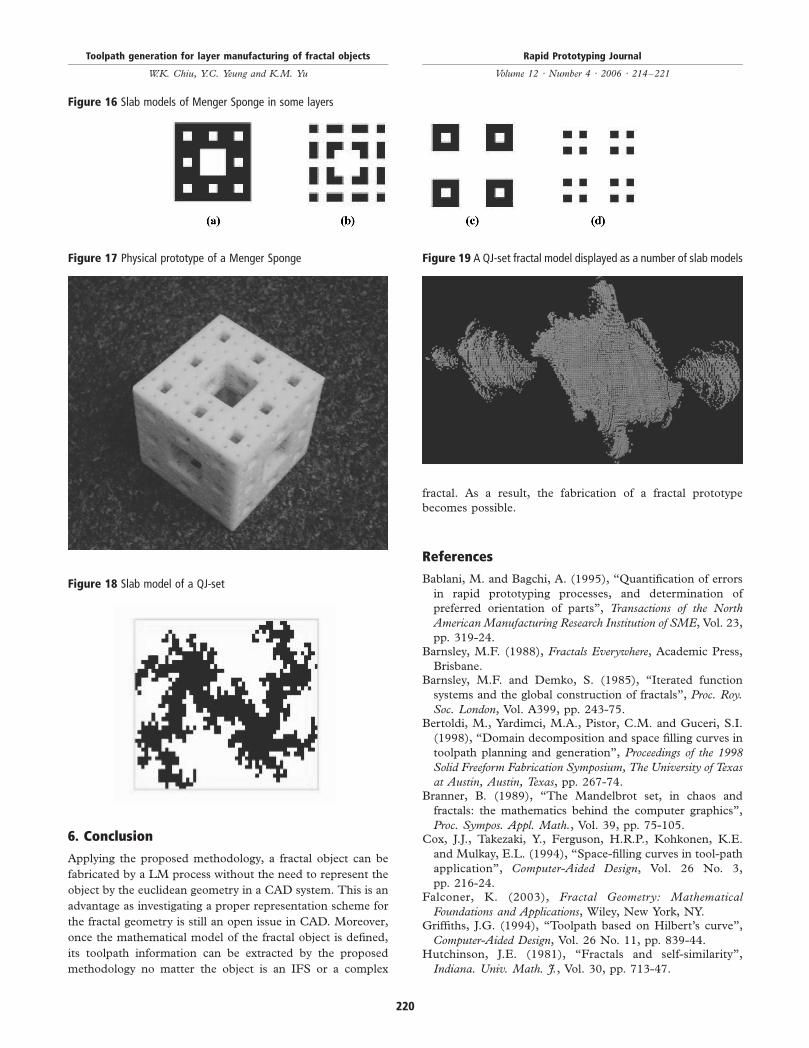
been given. In the first example, a Menger Sponge (Figure 15)
which is an IFS fractal model was fabricated by the FDM
process. Applying the proposed methodology, slab grid is
generated and 2D slab model was obtained in each layer, as
shown in Figure 16. In this simple example, no Part-IN pixels
are found. The boundary pixels are identified and the
boundary of the slab model is traced. The toolpath
information is generated and a physical prototype was
fabricated (Figure 17).In the second example, a QJ-set was used as an example.
Similarly, slab model in each layer must be obtained. In
Figure 18, an example slab model is shown. Based on the slab
models, the boundary in each layer is extracted and the
toolpath for the whole fractal object is generated accordingly.
5. Discussion
In this paper, a methodology is proposed for generating the
toolpath information of a fractal object from its mathematical
model for the LM technology. However, there are some
drawbacks that must be considered when this methodology is
applied. Firstly, there would be a large number of pixels in
each slab model and the computational effort for checking the
interior property of each pixel would be large. Moreover, the
amount of memory required for storing the slab models is also
needed to be considered. Secondly, each Part-IN pixel has to
be refined and similar problems are induced.The refining resolution of the methodology is set according
to the machine resolution. As mentioned above (such as that
shown in Figure 4), a fractal is infinitely complex when it is
magnified and it is impossible to obtain the exact shape of the
fractal unless the iteration process for generating the fractal is
terminated in a predefined level (or an approximation level).
As a result, it is reasonable to use the machine resolution as
the refining resolution as it infers the finest details that can be
made by the machine. The problem of the accuracy of the
prototype as compared to the model is now become the
problem of how fine a fractal prototype a user would like to
have.After the 2D pixels in each layer of a fractal are obtained, an
approximation model can be constructed by extruding each
2D pixel into a 3D voxel. For example, in Figure 19, the 2D
pixels of a QJ-set are extruded into a number of voxels. It
provides another possible method for visualizing the fractal
object.The proposed methodology can be applied to IFS or
complex fractal. However, some of the fractals are
constructed from more than one kind of fractal objects,
such as multi-IFS fractals (e.g. human body). In this case, the
methodology may need to be modified in order to handle this
type of fractal.
Figure 13 Refining the Part-IN pixel of a 2D slab model by quadtreeoperation
Figure 14 The boundary toolpath of the pixel (1, 3) in Figure 11
Figure 15 Menger Sponge
Toolpath generation for layer manufacturing of fractal objects
W.K. Chiu, Y.C. Yeung and K.M. Yu
Rapid Prototyping Journal
Volume 12 · Number 4 · 2006 · 214–221
219
6. Conclusion
Applying the proposed methodology, a fractal object can be
fabricated by a LM process without the need to represent the
object by the euclidean geometry in a CAD system. This is an
advantage as investigating a proper representation scheme for
the fractal geometry is still an open issue in CAD. Moreover,
once the mathematical model of the fractal object is defined,
its toolpath information can be extracted by the proposed
methodology no matter the object is an IFS or a complex
fractal. As a result, the fabrication of a fractal prototype
becomes possible.
References
Bablani, M. and Bagchi, A. (1995), “Quantification of errors
in rapid prototyping processes, and determination of
preferred orientation of parts”, Transactions of the North
American Manufacturing Research Institution of SME, Vol. 23,
pp. 319-24.Barnsley, M.F. (1988), Fractals Everywhere, Academic Press,
Brisbane.Barnsley, M.F. and Demko, S. (1985), “Iterated function
systems and the global construction of fractals”, Proc. Roy.
Soc. London, Vol. A399, pp. 243-75.Bertoldi, M., Yardimci, M.A., Pistor, C.M. and Guceri, S.I.
(1998), “Domain decomposition and space filling curves in
toolpath planning and generation”, Proceedings of the 1998
Solid Freeform Fabrication Symposium, The University of Texas
at Austin, Austin, Texas, pp. 267-74.Branner, B. (1989), “The Mandelbrot set, in chaos and
fractals: the mathematics behind the computer graphics”,
Proc. Sympos. Appl. Math., Vol. 39, pp. 75-105.Cox, J.J., Takezaki, Y., Ferguson, H.R.P., Kohkonen, K.E.
and Mulkay, E.L. (1994), “Space-filling curves in tool-path
pp. 216-24.Falconer, K. (2003), Fractal Geometry: Mathematical
Foundations and Applications, Wiley, New York, NY.Griffiths, J.G. (1994), “Toolpath based on Hilbert’s curve”,
Computer-Aided Design, Vol. 26 No. 11, pp. 839-44.Hutchinson, J.E. (1981), “Fractals and self-similarity”,
Indiana. Univ. Math. J., Vol. 30, pp. 713-47.
Figure 16 Slab models of Menger Sponge in some layers
Figure 17 Physical prototype of a Menger Sponge
Figure 18 Slab model of a QJ-set
Figure 19 A QJ-set fractal model displayed as a number of slab models
Toolpath generation for layer manufacturing of fractal objects
W.K. Chiu, Y.C. Yeung and K.M. Yu
Rapid Prototyping Journal
Volume 12 · Number 4 · 2006 · 214–221
220
Jamieson, R. and Hacker, H. (1995), “Direct slicing of CADmodels for rapid prototyping”, Rapid Prototyping Journal,Vol. 1 No. 2, pp. 4-12.
Kerekes, T. (1992), “Stereolithography builds computer-generated models of natural forms”, Rapid PrototypingReport, Vol. 2 No. 4, p. 1.
Lan, P.T., Chou, S.Y., Chen, L.L. and Gemmill, D. (1997),“Determining fabrication orientations for rapid prototypingwith stereolithography apparatus”, Computer-Aided Design,Vol. 29 No. 1, pp. 53-62.
Lin, F., Sun, W. and Yan, Y. (2001), “Optimization withminimum process error for layered manufacturingfabrication”, Rapid Prototyping Journal, Vol. 7 No. 2,pp. 73-81.
Mandelbrot, B. (1983), The Fractal Geometry of Nature, W.H.Freeman and Company, San Francisco, CA.
Mandelbrot, B.B. (1975), “Stochastic models for the earth’srelief, the shape and the fractal dimension of the coastlines,and the number-area rule for islands”, Proc. Nat. Acad. Sci.USA, Vol. 72, pp. 3825-8.
Mizugaki, Y. and Sakamoto, M. (1992), “Fractal pathgeneration for a metal-mold polishing robot system andits evaluation by the operability”, Annals of the CIRP,Vol. 41, pp. 531-4.
Moran, P.A.P. (1946), “Additive functions of intervals andHausdorff measure”, Proc. Camb. Phil. Soc., Vol. 42,pp. 15-23.
Mortenson, M.E. (1995), Geometric Modeling, 1st ed., Wily,New York, NY.
Pandey, P.M., Reddy, N.V. and Dhande, S.G. (2003),“Slicing procedures in layered manufacturing: a review”,Rapid Prototyping Journal, Vol. 9 No. 5, pp. 274-88.
Peitgen, H.O. and Richter, R.H. (1986), The Beauty ofFractals: Images of Complex Dynamical Systems, Springer,New York, NY.
Peitgen, H.O., Jugens, H. and Saupe, D. (1991), Fractals for
the Classroom Part 1: Introduction to Fractals and Chaos,
Springer-Verlag, New York, NY.Rojas, R. (1991), “A tutorial on efficient computer graphic
representations of the mandelbrot set”, Computers and
Graphics, Vol. 15 No. 1, pp. 91-100.Soo, S.C. and Yu, K.M. (2001), “Rapid prototyping using
fractal geometry”, Proceedings of the 12th Solid Freeform
Fabrication Symposium, University of Texas at Austin, Austin,
Texas, pp. 424-31.Soo, S.C. and Yu, K.M. (2002), “Toolpath generation for
fractal curve making”, International Journal of Advanced
Manufacturing Technology, Vol. 19 No. 1, pp. 32-48.Wasser, T., Jayal, A.D. and Pistor, C. (1999),
“Implementation and evaluation of novel buildstyles in
fused deposition modeling (FDM)”, Proceedings of the 10th
Solid Freeform Fabrication Symposium, University of Texas at
Austin, Austin, Texas, pp. 267-74.Williams, R.F. (1971), “Composition of contractions”, Bol.
Soc. Brasil. Mat., Vol. 2 No. 2, pp. 55-9.Xu, F., Loh, H.T. and Wong, Y.S. (1999), “Considerations
and selection of optimal orientation for different rapid