CHAPTER 1 TOOLROOMS AND TOOLS CHAPTER LEARNING OBJECTIVES Upon completing this chapter, you should be able to do the following: Describe toolroom organization. Explain how to inspect tools for damage. State the process used to issue tools. Describe the use of measuring tools in shop manufacture. Describe the procedure used to check the accuracy of measuring instruments. Before we discuss toolrooms and tools, we’ll give you an overview of the Machinery Repairman (MR) rating. The official description of the scope of the MR rating is to “perform organizational and intermediate maintenance on assigned equipment and in support of other ships, requiring the skillful use of lathes, milling machines, boring mills, grinders, power hacksaws, drill presses, and other machine tools; portable machinery; and handtools and measuring instruments found in a machine shop.” That is a very general statement not meant to define completely the types of skills and supporting knowledge that an MR is expected to have in the different paygrades. The job of restoring machinery to good working order, ranging from the fabrication of a simple pin or bushing to the complete rebuilding of an intricate gear system, requires skill of the highest order at each task level. Often, in the absence of dimensional drawings or other design information, an MR must depend upon ingenuity and know-how to successfully fabricate a repair part. One of the important characteristics you will gain from becoming a well-trained and skilled MR is versatility. As you gain knowledge and skill in the operation of the many different types of machines found in Navy machine shops, you will realize that even though a particular machine is used mostly for certain types of jobs, it may be capable of accepting many others. Your imagination will probably be your limiting factor; and if you keep your eyes, ears, and mind open, you will discover that there are many things going on around you that can broaden your base of knowledge. You will find pleasure and pride in developing new and more efficient ways to do something that has become so routine everyone else simply accepts the procedure currently being used as the only one that will work. The skill acquired by an MR in the Navy is easily translated into several skills found in the machine shops of private industry. In fact, you’d be surprised at the depth and range of your knowledge and skill compared to your civilian counterpart, based on a somewhat equal length of experience. The machinist trade in private industry breaks job descriptions into many different titles and skill levels. The beginning skill level and one in which you will surely become qualified is machine tool operator, a job often done by semiskilled workers. The primary requirement of the job is to observe the operation, disengage the machine in case of problems, and possibly maintain manual control over certain functions. Workers who do these jobs usually have the ability to operate a limited number of different types of machines. 1-1
Transcript
CHAPTER 1
TOOLROOMS AND TOOLS
CHAPTER LEARNING OBJECTIVES
Upon completing this chapter, you should be able to do the following:
Describe toolroom organization.
Explain how to inspect tools for damage.
State the process used to issue tools.
Describe the use of measuring tools in shop manufacture.
Describe the procedure used to check the accuracy of measuring instruments.
Before we discuss toolrooms and tools, we’ll giveyou an overview of the Machinery Repairman (MR)rating.
The official description of the scope of the MRrating is to “perform organizational and intermediatemaintenance on assigned equipment and in support ofother ships, requiring the skillful use of lathes, millingmachines, boring mills, grinders, power hacksaws,drill presses, and other machine tools; portablemachinery; and handtools and measuring instrumentsfound in a machine shop.” That is a very generalstatement not meant to define completely the types ofskills and supporting knowledge that an MR isexpected to have in the different paygrades.
The job of restoring machinery to good workingorder, ranging from the fabrication of a simple pin orbushing to the complete rebuilding of an intricate gearsystem, requires skill of the highest order at each tasklevel. Often, in the absence of dimensional drawingsor other design information, an MR must depend uponingenuity and know-how to successfully fabricate arepair part.
One of the important characteristics you will gainfrom becoming a well-trained and skilled MR isversatility. As you gain knowledge and skill in theoperation of the many different types of machinesfound in Navy machine shops, you will realize thateven though a particular machine is used mostly for
certain types of jobs, it may be capable of acceptingmany others. Your imagination will probably be yourlimiting factor; and if you keep your eyes, ears, andmind open, you will discover that there are manythings going on around you that can broaden yourbase of knowledge. You will find pleasure and pridein developing new and more efficient ways to dosomething that has become so routine everyone elsesimply accepts the procedure currently being used asthe only one that will work.
The skill acquired by an MR in the Navy is easilytranslated into several skills found in the machineshops of private industry. In fact, you’d be surprisedat the depth and range of your knowledge and skillcompared to your civilian counterpart, based on asomewhat equal length of experience. The machinisttrade in private industry breaks job descriptions intomany different titles and skill levels.
The beginning skill level and one in which youwill surely become qualified is machine tool operator,a job often done by semiskilled workers. The primaryrequirement of the job is to observe the operation,disengage the machine in case of problems, andpossibly maintain manual control over certainfunctions. Workers who do these jobs usually have theability to operate a limited number of different typesof machines.
1-1
Another job description found in private industryis layout man. The requirement of this job is to layout work that is to be machined by someone else. Anunderstanding of the operation and capabilities of thedifferent machines is required, as well as the ability toread blueprints. As you progress in your training inthe MR rating you will become proficient ininterpreting blueprints and in planning the requiredmachining operations. You will find that laying outintricate parts is not so difficult with this knowledge.
A third job description is set-up man, a job thatrequires considerable knowledge and skill, all withinwhat you can expect to gain as a MR. A set-up man isresponsible for placing each machine accessory andcutting tool in the exact position required to permitaccurate production of work by a machine tooloperator.
An all-around machinist in private industry is thejob for which the average MR would qualify as far asknowledge and skill are concerned. This person isable to operate all machines in the shop andmanufacture parts from blueprints. Some MRs willadvance their knowledge and skills throughout theirNavy career to the point that they can move into a jobas a tool and die maker with little trouble. They alsoacquire a thorough knowledge of engineering datarelated to design limitations, shop math, andmetallurgy. There are many other related fields inwhich an experienced MR could perform—instrument maker, research and developmentmachinist, toolroom operator, quality assuranceinspector and, of course, the supervisory jobs such asforeman or superintendent.
The obvious key to holding down a position ofhigher skill, responsibility, and pay is the same both inthe Navy and in private industry. You must workhard, take advantage of the skills and knowledge ofthose around you, and take pride in what you doregardless of how unimportant it may seem to you.You have a great opportunity ahead of you as an MRin the Navy; a chance to make your future moresecure than it might have been.
Your proficiency as an MR is greatly influencedby your knowledge of tools and your skills in usingthem. You will need to become familiar with thecorrect use and care of the many powered andnonpowered handtools, measuring instruments, andgauges you will use in your job.
This training manual will provide information onthe tools and instruments used primarily by an MR.You can find additional information on tools used bythe many different naval ratings in USE and CARE ofHAND TOOLS and MEASURING TOOLS,NAVEDTRA 12085.
TOOLROOM SAFETY
The toolroom is relatively small, and a largequantity of different tools are stored there. It canbecome very dangerous if all items are not kept storedin their proper places. At sea the toolroom can beespecially hazardous if you don’t secure all drawers,bins, pegboards, and other storage facilities. Firehazards are sometimes overlooked in the toolroom.When you consider the flammable liquids and wipingrags stored in or issued from the toolroom, you realizethere is a real danger present.
As a toolroom keeper, you play a very importantpart in creating a safe working environment. Severalof your jobs are directly connected to the goodworking order and safe use of tools in the shop. If youissue an improperly ground twist drill to someonewho does not have the experience to recognize thedefect, the chances of the person being injured if thedrill “digs in” or throws the workpiece out of the drillpress would be very real. A wrench that has beensprung or worn oversize can become a real“knucklebuster” to any unsuspecting user. An outsidemicrometer out of calibration can cause trouble whensomeone is trying to press fit two parts together usinga hydraulic press. The list of potential disasters thatyou can prevent is endless. The important thing toremember is that you as a toolroom keeper contributemore to the mission of the Navy than first meets theeye. If you are ever in doubt concerning toolroomsafety, consult your supervisor or Navy OccupationalSafety and Health (NAVOSH) Program Manual forForces Afloat, OPNAVINST 5100.19B.
TOOLROOM ORGANIZATION
You may be given responsibility for the operationof the tool crib or tool-issuing room. Make sure thatthe necessary tools are available and in goodcondition and that an adequate supply of consumableitems (oil, wiping rags, bolts, nuts, and screws) isavailable.
It’s easy to operate and maintain a toolroom if thecorrect procedures and methods are used to set up the
1-2
28.333.1
system. Some of the basic considerations are (1) theissue and custody of tools; (2) replacement of broken,worn, or lost tools; and (3) proper storage andmaintenance of tools.
Shipboard toolrooms are limited in size by thedesign of the ship. Therefore, the space must be usedas efficiently as possible. Since the number of toolsrequired aboard ship is extensive, toolrooms usuallytend to be overcrowded. Certain peculiarities inshipboard toolrooms also require consideration. Forexample, the motion of the ship at sea requires thattools be made secure to prevent movement. Themoisture in the air requires that the tools be protectedfrom corrosion.
It’s difficult to change permanent bins, shelves, anddrawers in the toolroom. However, you can reorganizeexisting storage spaces by dividing larger bins andrelocating tools to provide better use of space.
Figure 1-1.—Method of tool storage.
Hammers, wrenches, and other tools that do nothave cutting edges are normally stored in bins. Theyalso may be segregated by size or other designation.Tools with cutting edges require more space toprevent damage to the cutting edges. These tools arestored on shelves lined with wood or felt, onpegboards, or on hanging racks. Pegboards areespecially adaptable for tools such as milling cutters.Make provisions to keep these tools from falling offthe boards when the ship is rolling. Store precisiontools (micrometers, dial indicators, and so forth) infelt-lined wooden boxes in a cabinet to reduce theeffects of vibration. This arrangement allows a quickdaily inventory. It also prevents the instruments frombeing damaged by contact with other tools. Userotating bins to store large supplies of small parts,such as nuts and bolts. Rotating bins provide rapidselection from a wide range of sizes. Figures 1-1,
1-3
1-2, and 1-3 show some of the common methods oftool storage.
Place frequently used tools near the issuing doorso they are readily available. Place seldom used toolsin out of the way areas such as on top of bins or inspaces that cannot be used efficiently because of sizeand shape. Place heavy tools in spaces or areas wherea minimum of lifting is required.
Mark all storage areas such as bins, drawers, andlockers clearly to help locate tools. Make thesemarkings permanent- either stencil them with paintor mark them with stamped metal tags.
TOOL INSPECTION
If you are the toolroom keeper, you’ll beresponsible for the condition of all the tools andequipment in the toolroom. This is a very importantjob. Inspect all tools as they are returned to determineif they need repairs or adjustment. NEVER issuedamaged tools since they may harm shop equipmentor personnel. Set aside a space for damaged tools toprevent issue of these tools until they have beenrepaired. Send any dull cutting tools to the grind shopfor regrinding. Properly dispose of any cutting toolsthat can’t be reground.
Wipe clean all returned tools and give their metalsurfaces a light coat of oil. Check all precision toolsupon issue and return to determine if they are
accurate. Keep all spaces clean and free of dust toprevent foreign matter from getting into the workingparts of tools. Plan to spend a portion of each dayreconditioning damaged tools. This keeps the toolsavailable for issue and prevents an accumulation ofdamaged tools.
CONTROL OF TOOLS
There are two common methods of tool issuecontrol: the tool check system and the mimeographedform or tool chit system. Some toolrooms may use acombination of these systems. For example, you mayuse tool checks for machine shop personnel, andmimeographed forms for personnel outside the shop.
Tool checks are either metal or plastic disksstamped with numbers that identify the borrower. Inthis system the borrower presents a check for eachtool, and the disk is placed on a peg near the spacefrom which the tool was taken. The advantage of thissystem is that very little time is spent completing theprocess.
If the tools are loaned to all departments in theship, printed forms generally are used. The form hasa space to list the tools, the borrower’s name, thedivision or department, and the date. This systemallows anyone in the ship’s crew to borrow tools, andit keeps the toolroom keeper informed as to who hasthe tools and how long they have been out.
28.334
Figure 1-2.—Method of tool storage.
1-4
28.335
Figure 1-3.—Method of tool storage.
1-5
You must know the location of tools andequipment out on loan, how long tools have been out,and the amount of equipment and consumablesupplies you have on hand. To know this, you’ll haveto make periodic inventories. The inventory consistsof a count of all tools, by type, in the toolroom andthose out on loan. Inventories help you decidewhether more strict control of equipment is neededand if you need to procure more tools and equipment.
Some selected items, called controlled equipage,will require an increased level of management andcontrol due to their high cost, vulnerability topilferage, or importance to the ship’s mission. Thenumber of tools and instruments in this category isgenerally small. However, it is important that you beaware of controlled equipage items. You can getdetailed information about the designation ofcontrolled equipage from the supply department ofyour activity. When these tools are received from thesupply department, your department head will berequired to sign a custody card for each item,indicating a definite responsibility for management ofthe item. The department head will then requiresigned custody cards from personnel assigned to thedivision or shop where the item will be stored andused. As a toolroom keeper, you may control theissue of these tools and ensure their good condition.If these special tools are lost or broken beyond repair,you cannot replace them until the correct surveyprocedures have been completed. Conduct formalinventories of these items periodically as directed byyour division officer or department head.
MEASURING INSTRUMENTS
Practically all shop jobs require measuring orgauging. You will most likely measure or gauge flator round stock; the outside diameters of rods, shafts,or bolts; slots, grooves, and other openings; threadpitch and angle; spaces between surfaces; or anglesand circles.
For some of these operations, you’ll have a choiceof which instrument to use, but in other instancesyou’ll need a specific instrument. For example, whenprecision is not important, a simple rule or tape willbe suitable. In other instances, when precision isimportant, you’ll need a micrometer.
The term gauge, as used in this chapter identifiesany device that can be used to determine the size orshape of an object. There is no significant differencebetween gauges and measuring instruments. They are
Figure 1-4.—Common types of micrometers.
both used to compare the size or shape of an objectagainst a scale or fixed dimension. However, there isa distinction between measuring and gauging that iseasily explained by an example. Suppose you areturning work on a lathe and want to know thediameter of the work. Take a micrometer, or perhapsan outside caliper, adjust its opening to the exactdiameter of the workpiece, and determine thatdimension numerically. On the other hand, if youwant to turn a piece of work down to a certain sizewithout frequently taking time to measure it, set thecaliper at a reading slightly greater than the finaldimension; then, at intervals during turningoperations, gauge, or “size,” the workpiece with thelocked instrument. After you have reduced theworkpiece dimension to the dimension set on theinstrument, you will, of course, need to measure thework as you finish it to the exact dimension.
1-6
ADJUSTABLE GAUGES
You can adjust adjustable gauges by moving thescale or by moving the gauging surface to thedimensions of the object being measured or gauged.For example, on a dial indicator, you can adjust theface to align the indicating hand with the zero point onthe dial. On verniers, however, you move themeasuring surface to the dimensions of the objectbeing measured.
Micrometers
Micrometers are probably the most used precisionmeasuring instruments in a machine shop. There aremany different types, each designed to measuresurfaces for various applications and configurationsof workpieces. The degree of accuracy also varies,with the most common graduations ranging fromone-thousandth (0.001) of an inch to oneten-thousandth (0.0001) of an inch. You’ll findinformation on the procedure used to interpret thereadings on micrometers in USE and CARE of HANDTOOLS and MEASURING TOOLS, NAVEDTRA12085. We have provided brief descriptions of themore common types of micrometers in the followingparagraphs.
OUTSIDE MICROMETER.—Outside microm-eters (figs. 1-4 and 1-5), are used to measure thethickness or the outside diameter of parts. They areavailable in sizes ranging from 1 inch to about 96inches in steps of 1 inch. The larger sizes normallycome as a set with interchangeable anvils that providea range of several inches. The anvils have anadjusting nut and a locking nut to allow you to set themicrometer with a micrometer standard. Regardlessof the degree of accuracy designed into themicrometer, the skill applied by each individual is theprimary factor in determining accuracy and reliabilityin measurements. Training and practice will make youproficient in using this tool.
INSIDE MICROMETER.—An inside microm-eter (fig. 1-4) is used to measure inside diameters orbetween parallel surfaces. They are available in sizesranging from 0.200 inch to over 100 inches. Theindividual interchangeable extension rods that may beassembled to the micrometer head vary in size by 1inch. A small sleeve or bushing, which is 0.500 inchlong, is used with these rods in most insidemicrometer sets to provide the complete range ofsizes. It’s slightly more difficult to use the insidemicrometer than the outside micrometer-there ismore chance that you won’t get the same “feel” ormeasurement each time you check the same surface.
28.321
Figure 1-5.—Nomenclature of an outside micrometer caliper.
1-7
The correct way to measure an inside diameter isto hold the micrometer in place with one hand as youfeel for the maximum possible setting of themicrometer by rocking the extension rod from left toright and in and out of the hole. Adjust the micrometerto a slightly larger measurement after each series ofrocking movements until you can no longer rock therod from left to right. At that point, you should feel avery slight drag on the in and out movement. Thereare no specific guidelines on the number of positionswithin a hole that should be measured. If you arechecking for taper, take measurements as far apart aspossible within the hole. If you are checking forroundness or concentricity of a hole, take severalmeasurements at different angular positions in thesame area of the hole. You may take the readingdirectly from the inside micrometer head, or you mayuse an outside micrometer to measure the insidemicrometer.
DEPTH MICROMETER.—A depth micrometer(fig. 1-4) is used to measure the depth of holes, slots,counterbores, and recesses, and the distance from asurface to some recessed part. This type ofmicrometer is read exactly opposite from the methodused to read an outside micrometer. The zero islocated toward the closed end of the thimble. Themeasurement is read in reverse and increases inamount (depth) as the thimble moves toward the baseof the instrument. The extension rods come eitherround or flat (blade-like) to permit measuring anarrow, deep recess or grooves.
THREAD MICROMETER.—The threadmicrometer (fig. 1-4) is used to measure the depth ofthreads that have an included angle of 60°. Themeasurement obtained represents the pitch diameterof the thread. They are available in sizes that measurepitch diameters up to 2 inches. Each micrometer hasa given range of number of threads per inch that canbe measured correctly. You’ll find additionalinformation on this micrometer in chapter 6.
BALL MICROMETER.—This type of microm-eter (not shown) has a rounded anvil and a flatspindle. It‘s used to check the wall thickness ofcylinders, sleeves, rings, and other parts that have ahole bored in a piece of material. The rounded anvilis placed inside the hole and the spindle is broughtinto contact with the outside diameter. Ballattachments that fit over the anvil of regular outsidemicrometers are also available. When using theattachments, you must compensate for the diameter ofthe ball as you read the micrometer.
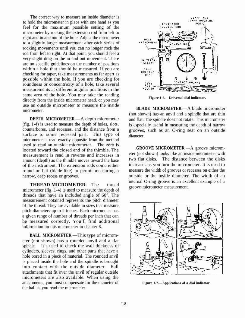
Figure 1-6.—Universal dial indicator.
BLADE MICROMETER.—A blade micrometer(not shown) has an anvil and a spindle that are thinand flat. The spindle does not rotate. This micrometeris especially useful in measuring the depth of narrowgrooves, such as an O-ring seat on an outsidediameter.
GROOVE MICROMETER.—A groove microm-eter (not shown) looks like an inside micrometer withtwo flat disks. The distance between the disksincreases as you turn the micrometer. It is used tomeasure the width of grooves or recesses on either theoutside or the inside diameter. The width of aninternal O-ring groove is an excellent example of agroove micrometer measurement.
Figure 1-7.—Applications of a dial indicator.
1-8
Dial Indicator
MRs use dial indicators to set up work inmachines and to check the alignment of machinery.You’ll need a lot of practice to become proficient inthe use of this instrument. You should use it as oftenas possible to help you do more accurate work.
Dial indicator sets (fig. 1-6) usually have severalcomponents that permit a wide variation of uses. Forexample, the contact points allow use on differenttypes of surfaces, the universal sleeve permitsflexibility of setup, the clamp and holding rods permitsetting the indicator to the work, the hole attachmentindicates variation or run out of inside surfaces ofholes, and the tool post holder can be used in lathesetups. Figure 1-7 shows some practical applicationsof dial indicators.
Dial indicators come in different degrees ofaccuracy. Some will give readings to oneten-thousandth (0.0001) of an inch, while others will
indicate to only one five-thousandth (0.005) of aninch. Dial indicators also differ in the total range oramount they will indicate. If a dial indicator has atotal of one hundred-thousandth (0.100) of an inch ingraduations on its face and has a total range of twohundred-thousandths (0.200) of an inch, the needlewill only make two revolutions before it begins toexceed its limit and jams up. The degree of accuracyand range of a dial indicator is usually shown on itsface. Before you use a dial indicator, carefullydepress the contact point and release it slowly; rotatethe movable dial face so the dial needle is on zero.Depress and release the contact point again and checkto make sure the dial pointer returns to zero; if it doesnot, have the dial indicator checked for accuracy.
Vernier Caliper
You can use a vernier caliper (fig. 1-8) to measureboth inside and outside dimensions. Position the
28 .314Figure 1-8.—Vernier caliper.
1-9
appropriate sides of the jaws on the surface to bemeasured and read the caliper from the side markedinside or outside as required. There is a difference inthe zero marks on the two sides that is equal to thethickness of the tips of the two jaws, so be sure to readthe correct side. Vernier calipers are available in sizesranging from 6 inches to 6 feet and are graduated inincrements of thousandths (0.001) of an inch. Thescales on vernier calipers made by differentmanufacturers may vary slightly in length or numberof divisions; however, they are read basically thesame way. See USE and CARE of HAND TOOLS andMEASURING TOOLS, NAVEDTRA 12085, forinstructions on how to interpret the readings.
Vernier Height Gauge
A vernier height gauge (fig. 1-9) is used to lay outwork for machining operations or to check the
dimensions on surfaces that have been machined.Attachments for the gauge include the offset scribeshown attached to the gauge in figure 1-9. Theoffset scribe lets you measure from the surface platewith readings taken directly from the scale withoutthe need for calculations. As you can see in figure1-9, if you were using a straight scribe, you wouldhave to calculate the actual height by taking intoaccount the distance between the surface plate andthe zero mark. Some models have a slot in the basefor the scribe to move down to the surface and ascale that permits direct reading. Anotherattachment is a rod that permits depth readings.Small dial indicators that connect to the scribepermit extremely close work when you check or layout work. Read a vernier height gauge the sameway you read a vernier caliper.
Figure 1-9.—Vernier height gauge.
1-10
Dial Vernier Caliper
A dial vernier caliper (fig. 1-10) looks much likea standard vernier caliper and is also graduated inone-thousandths (0.001) of an inch. The main
difference is that instead of a double scale, as on thevernier caliper, the dial vernier has the inches markedonly along the main body of the caliper and a dial thatindicates thousandths (0.001) of an inch. The rangeof the dial vernier caliper is usually 6 inches.
28.315
Figure 1-10.—Dial vernier caliper.
1-11
Dial Bore Gauge
The dial bore gauge is one of the most accuratetools used to measure a cylindrical bore or check abore for out-of-roundness or taper, (fig. 1-11). It doesnot give a direct measurement; it gives you theamount of deviation from a preset size or the amountof deviation from one part of the bore to another. Amaster ring gauge is used to preset the gauge. A dialbore gauge has two stationary spring-loaded pointsand an adjustable point to permit a variation in range.These three points are evenly spaced to allow accuratecentering of the tool in the bore. A fourth point, thetip of the dial indicator, is located between the twostationary points. By simply rocking the tool in thebore, you can observe the amount of variation on thedial. Most models are accurate to within oneten-thousandth (0.0001) of an inch.
Internal Groove Gauge
The internal groove gauge (not shown) may beused to measure the depth of an O-ring groove orother recesses inside a bore. This tool lets youmeasure a deeper recess and one located farther backin the bore than you could with an inside caliper. Aswith the dial bore gauge, you must set this tool withgauge blocks, a vernier caliper, or an outsidemicrometer. The reading taken from the dial indicatoron the groove gauge represents the differencebetween the desired recess or groove depth and themeasured depth.
Universal Vernier Bevel Protractor
The universal vernier bevel protractor (fig. 1-12)is used to lay out or measure angles on work to veryclose tolerances. The vernier scale on the tool permitsmeasuring an angle to within 1/12° (5 minutes) andcan be used completely through 360°. Interpretingthe reading on the protractor is similar to the methodused on the vernier caliper.
Universal Bevel
The universal bevel (fig. 1-13) has an offset in theblade. The offset makes it useful for bevel gear workand to check angles on lathe workpieces that cannotbe reached with an ordinary bevel. Set and check theuniversal bevel with the protractor, or another suitableangle-measuring device, to get the angle you need.
Use a gear tooth vernier (fig. 1-14) to measure thethickness of a gear tooth on the pitch circle and thedistance from the top of the tooth to the pitch chord, atthe same time. Read the vernier scale on this tool inthe same way as other verniers, but note thatgraduations on the main scale are 0.020 inch apartinstead of 0.025 inch.
Cutter Clearance Gauge
The cutter clearance gauge (fig. 1-15) is one ofthe simplest to use. You can gauge clearance on allstyles of plain milling cutters that have more than 8teeth and a diameter range from 1/2 inch to 8 inches.To gauge a tooth with this instrument, bring thesurfaces of the “V” into contact with the cutter andlower the gauge blade to the tooth to be gauged.
Rotate the cutter sufficiently to bring the tooth faceinto contact with the gauge blade. If the angle ofclearance on the tooth is correct, it will correspondwith the angle of the gauge blade. Cutter clearancegauges that have an adjustable gauge blade to checkclearance angles of 0° to 30° are also available.
Adjustable Parallel
The adjustable parallel in figure 1-16 consists oftwo wedges connected on their inclined surfaces by asliding dovetail. An adjustable parallel can be lockedat any height between its maximum and minimumlimits. This instrument, constructed to about the sameaccuracy of dimensions as parallel blocks, is very usefulto level and position setups in a milling machine or in ashaper vise. You should normally use an outsidemicrometer to set the adjustable parallel for height.
1-14
Figure 1-15.—Cutter clearance gauge.
Figure 1-16.—Adjustable parallel.
1-15
Figure 1-17.—Setting a dimension on a surface gauge.
Surface Gauge
A surface gauge (fig. 1- 17) is useful in gauging ormeasuring operations. It is used primarily in layoutand alignment work and it is used with a scribe totransfer dimensions and layout lines. In some cases adial indicator is used with the surface gauge to checktrueness or alignment.
FIXED GAUGES
Fixed gauges cannot be adjusted. Generally, theycan be divided into two categories, graduated andnongraduated. The accuracy of your work, when youuse fixed gauges, will depend on your ability tocompare between the work and the gauge. Forexample, a skilled machinist can take a dimensionaccurately to within 0.005 of an inch or less using acommon rule. Experience will increase your abilityto take accurate measurements.
Graduated Gauges
Graduated gauges are direct reading gauges thathave scales inscribed on them, enabling you to take areading while using the gauge. The gauges in thisgroup are rules, scales, thread gauges, center gauges,feeler gauges, and radius gauges.
RULES.—The steel rule with holder set (fig.1-18, view A) is convenient for measuring recesses.It has a long tubular handle with a split chuck forholding the ruled blade. The chuck can be adjusted bya knurled nut at the top of the holder, allowing the ruleto be set at various angles. The set has rules rangingfrom 1/4 to 1 inch in length.
The angle rule (fig. 1-18, view B) is useful inmeasuring small work mounted between centers on alathe. The long side of the rule (ungraduated) isplaced even with one shoulder of the work. Thegraduated angle side of the rule can then be positionedeasily over the work.
Another useful device is the keyseat rule (fig.1-18, view C). It has a straightedge and a 6-inchmachinist’s-type rule arranged to form a right anglesquare. This rule and straightedge combination, whenapplied to the surface of a cylindrical workpiece,makes an excellent guide for drawing or scribinglayout lines parallel to the axis of the work. Thisdevice is very convenient when making keyseatlayouts on shafts.
You must take care of your rules if you expectthem to give accurate measurements. Do not allowthem to become battered, covered with rust, or
1-16
Figure 1-18.—Speclal rules for shop use.
otherwise damaged so that the markings cannot beread easily. Never use rules for scrapers. Once ruleslose their sharp edges and square corners, theiraccuracy is decreased.
SCALES.—A scale is similar in appearance to arule, since its surface is graduated into regular spaces.The graduations on a scale, however, differ fromthose on a rule because they are either larger orsmaller than the measurements indicated. Forexample, a half-size scale is graduated so that 1 inchon the scale is equivalent to an actual measurement of2 inches; a 12-inch long scale of this type isequivalent to 24 inches. A scale, therefore, givesproportional measurements instead of the actualmeasurements obtained with a rule. Like rules, scalesare made of wood, plastic, or metal, and theygenerally range from 6 to 24 inches.
ACME THREAD TOOL GAUGE.—The threadgauge (fig. 1-19) is used to both grind the tool used tomachine Acme threads and to set the tool up in thelathe. The sides of the Acme thread have an included
1-17
Figure 1-19.—Acme thread gauges.
Figure 1-20.—Center gauge.
angle of 29° (14 1/2° to each side), and this is theangle made into the gauge. The width of the flat onthe point of the tool varies according to the number ofthreads per inch. The gauge provides different slotsfor you to use as a guide when you grind the tool. It’seasy to set up the tool in the lathe. First, make surethat the tool is centered on the work as far as height isconcerned. Then, with the gauge edge laid parallel tothe centerline of the work, adjust the side of your tooluntil it fits the angle on the gauge very closely.
feeler gauge, practice with it on openings of knowndimensions.
RADIUS GAUGE.—The radius gauge (fig. 1-22)is often underrated in its usefulness to the machinist.Whenever possible, the design of most parts includesa radius located at the shoulder formed when a changeis made in the diameter. This gives the part an addedmargin of strength at that particular place. When asquare shoulder is machined in a place where a radiusshould have been, the possibility that the part will failby bending or cracking is increased. The blades ofmost radius gauges have both concave (inside curve)and convex (outside curve) radii in the common sizes.
Nongraduated Gauges
Nongraduated gauges are used primarily asstandards, or to determine the accuracy of form orshape. They include the straightedge, machinist square,sine bar, parallel blocks, gauge blocks, ring and pluggauges, and thread-measuring wires. We’ll explain theuse of these gauges in the following paragraphs.
STRAIGHTEDGES. —Straightedges look verymuch like rules, except they are not graduated. Theyare used primarily to check surfaces for straightness;however, they can also be used as guides to help drawor scribe straight lines. Two types of straightedges areshown in figure 1-23. View A shows a straightedgemade of steel that is hardened on the edges to preventwear; it is the one you will probably use most often.The straightedge shown in view B has a knife edgeand is used for work requiring extreme accuracy.
CENTER GAUGE.—Use the center gauge(fig. 1-20) like the Acme thread gauge. Each notch andthe point of the gauge has an included angle of 60°. Usethe gauge primarily to check and to set the angle of theV-sharp and other 60° standard threading tools. Youmay also use it to check the lathe centers. The edges aregraduated into 1/4, 1/24, 1/32, and 1/64 inch for ease indetermining the pitch of threads on screws.
FEELER GAUGE.—Use a feeler (thickness)gauge (fig. 1-21) to determine distances between twoclosely mating surfaces. When you USC a combinationof blades to get a desired gauge thickness, try to placethe thinner blades between the heavier ones to protectthe thinner blades and to prevent their kinking. Donot force blades into openings that are too small; theblades may bend and kink. To get the feel of using a
Always keep a straightedge in a box when it is notin use. Some straightedges are marked with two arrows,one near each end, which indicate balance points. Whena box is not provided, place resting pads on a flat surfacein a storage area where no damage to the straightedgewill occur from other tools. Then, place the straightedgeso the two balance points sit on the resting pads.
MACHINIST’S SQUARE.—The most commontype of machinist’s square has a hardened steel bladesecurely attached to a beam. The steel blade is NOTgraduated. (See fig. 1-24.) This instrument is veryuseful in checking right angles and in setting up workon shapers, milling machines, and drilling machines.The size of machinist’s squares ranges from 1 1/2 to36 inches in blade length. You should take the samecare of machinist’s squares, in storage and use, as youdo with a micrometer.
SINE BAR.—A sine bar (fig. 1-25) is a precisiontool used to establish angles that require extremely closeaccuracy. When used in conjunction with a surfaceplate and gauge blocks, angles are accurate to 1 minute(1/60°). The sine bar is used to measure angles on workand to lay out an angle on work to be machined, or workmay be mounted directly to the sine bar for machining.The cylindrical rolls and the parallel bar, which make upthe sine bar, are all precision ground and accuratelypositioned to permit such close measurements. Be sureto repair any scratches, nicks, or other damage beforeyou use the sine bar, and take care in using and storingthe sine bar. Instructions on using the sine bar areincluded in chapter 2.
PARALLEL BLOCKS.—Parallel blocks(fig. 1-26) are hardened, ground steel bars that areused to lay out work or set up work for machining.The surfaces of the parallel block are all eitherparallel or perpendicular, as appropriate, and can beused to position work in a variety of setups with
28.319
Figure 1-26.—Parallel blocks.
1-19
accuracy. They generally come in matched pairs andin standard fractional dimensions. Use care in storingand handling them to prevent damage. If it becomesnecessary to regrind the parallel blocks, be sure tochange the size stamped on the ends of the blocks.
GAUGE BLOCKS.—Gauge blocks (not shown)are used as master gauges to set and check othergauges and instruments. Their accuracy is fromtwo-millionths (0.000002) of an inch toeight-millionths (0.000008) of an inch, depending onthe grade of the set. To visualize this minute amount,consider that the average thickness of a human hairdivided 1,500 times equals 0.000002 inch. Thisdegree of accuracy applies to the thickness of thegauge block, the parallelism of the sides, and theflatness of the surfaces. To attain this accuracy, a finegrade of hardenable alloy steel is ground and thenlapped. The gauge blocks are so smooth and flat thatwhen they are “wrung” or placed one atop the otheryou cannot separate them by pulling straight out. Aset of gauge blocks has enough different size blocksthat you can establish any measurement within theaccuracy and range of the set. As you might expect,anything so accurate requires exceptional care toprevent damage and to ensure continued accuracy. Adust-free temperature-controlled atmosphere ispreferred. After use, wipe each block clean of allmarks and fingerprints, and coat it with a thin layer ofwhite petrolatum to prevent rust.
RING AND PLUG GAUGES.—A ring gauge(fig. 1-27, views C and D) is a cylindrically-shapeddisk that has a precisely ground bore. Ring gaugesare used to check machined diameters by sliding thegauge over the surface. Straight, tapered, andthreaded diameters can be checked by using theappropriate gauge. The ring gauge is also used to setother measuring instruments to the basic dimensionrequired for their operation. Normally, ring gaugesare available with a GO and a NOT GO size thatrepresents the tolerance allowed for the particular sizeor job.
A plug gauge (fig. 1-27, views A and B) is usedfor the same types of jobs as a ring gauge. However,it is a solid shaft-shaped bar that has a preciselyground diameter used to check inside diameters orbores.
THREAD MEASURING WIRES.—Thesewires provide the most accurate method of measuringthe fit or pitch diameter of threads, without going intothe expensive and sophisticated optical and com-parator equipment. The wires are accurately sized,
depending on the number of threads per inch. Whenthey are laid over the threads in a position that allowsan outside micrometer to measure the distancebetween them, the pitch diameter of the threads can bedetermined. Sets are available that contain all themore common sizes. Detailed information on com-puting and using the wire method for measuring iscovered in chapter 6.
CARE AND MAINTENANCE OFMEASURING INSTRUMENTS
The proper care and maintenance of precisioninstruments is very important to a conscientious MR.To help you maintain your instruments in the mostaccurate and reliable condition possible, the Navy hasestablished a calibration program. It providescalibration technicians with the required standardsand procedures, and a schedule of how often aninstrument must be calibrated to be reliable. When aninstrument is calibrated, a sticker is affixed to itshowing the date the calibration was done and the datethe next calibration is due. Whenever possible, youshould use the Navy calibration program to verify theaccuracy of your instruments. Some repair jobs, dueto their sensitive nature, demand the reliabilityprovided by the program. Information concerning theprocedures that you can use in the shop to check theaccuracy of an instrument is contained in thefollowing paragraphs.
Figure 1-27.—Ring gauges and plug gauges.
1-20
MICROMETERS
The micrometer is one of the most used, and oftenone of the most abused, precision measuringinstruments in the shop. Careful observation of thedo’s and don’ts in the following list will enable you totake proper care of the micrometer you use:
Always stop the work before taking a measure-ment. Do NOT measure moving parts because themicrometer may get caught in the rotating work andbe severely damaged.
Always open a micrometer by holding theframe with one hand and turning the knurled sleevewith the other hand. Never open a micrometer bytwirling the frame, because such practice will putunnecessary strain on the instrument and causeexcessive wear of the threads.
Apply only moderate force to the knurledthimble when you take a measurement. Always usethe friction slip ratchet if there is one on theinstrument. Too much pressure on the knurled sleevewill not only result in an inaccurate reading, but mayalso cause the frame to spring, forcing the measuringsurfaces out of line.
When a micrometer is not in actual use, place itwhere it is not likely to be dropped. Dropping amicrometer can cause the frame to spring; if dropped,the instrument should be checked for accuracy beforeany further readings are taken.
Before a micrometer is returned to stowage,back the spindle away from the anvil, wipe all exteriorsurfaces with a clean, soft cloth, and coat the surfaceswith a light oil. Do not reset the measuring surfacesto close contact because the protecting film of oil inthese surfaces will be squeezed out.
A micrometer caliper should be checked forzero setting (and adjusted when necessary) as a matterof routine to ensure that reliable readings are beingobtained. To do this, proceed as follows:
1. Wipe the measuring faces, making sure thatthey are perfectly clean, and then bring the spindleinto contact with the anvil. Use the same moderateforce that you ordinarily use when taking ameasurement. The reading should be zero; if it is not,the micrometer needs further checking.
2. If the reading is more than zero, examinethe edges of the measuring faces for burrs. Shouldburrs be present, remove them with a small slip of
oilstone; clean the measuring surfaces again, and thenrecheck the micrometer for zero setting.
3. If the reading is less than zero, or if you donot obtain a zero reading after making the correctiondescribed in step 2, you will need to adjust thespindle-thimble relationship. The method for settingzero differs considerably between makes ofmicrometers. Some makes have a thimble cap thatlocks the thimble to the spindle; some have a specialrotatable sleeve on the barrel that can be unlocked;and some have an adjustable anvil.
To make adjustments to micrometers followthese steps:
1. To adjust the THIMBLE-CAP TYPE, backthe spindle away from the anvil, release the thimblecap with the small spanner wrench provided for thatpurpose, and bring the spindle into contact with theanvil. Hold the spindle firmly with one hand androtate the thimble to zero with the other; after zerorelation has been established, rotate the spindlecounterclockwise to open the micrometer, and thentighten the thimble cap. After tightening the cap,check the zero setting again to be sure thethimble-spindle relation was not disturbed while thecap was being tightened.
2. To adjust the ROTATABLE SLEEVETYPE, unlock the barrel sleeve with the small spannerwrench provided for that purpose, bring the spindleinto contact with the anvil, and rotate the sleeve intoalignment with the zero mark on the thimble. Aftercompleting the alignment, back the spindle away fromthe anvil, and retighten the barrel sleeve locking nut.Recheck for zero setting, to be sure you did notdisturb the thimble-sleeve relationship whiletightening the lock nut.
3. To set zero on the ADJUSTABLE ANVILTYPE, bring the thimble to zero reading, lock thespindle if a spindle lock is provided, and loosen theanvil lock screw. After you have loosened the lockscrew, bring the anvil into contact with the spindle,making sure the thimble is still set on zero. Tightenthe anvil setscrew lock nut slightly, unlock thespindle, and back the spindle away from the anvil;then lock the anvil setscrew firmly. After locking thesetscrew, check the micrometer for zero setting tomake sure you did not move the anvil out of positionwhile you tightened the setscrew.
l The zero check and methods of adjustment ofcourse apply directly to micrometers that willmeasure to zero; the PROCEDURE FOR LARGER
1-21
MICROMETERS is essentially the same except that astandard must be placed between the anvil and thespindle to get a zero measuring reference. Forexample, a 2-inch micrometer is furnished with a1-inch standard. To check for zero setting, place thestandard between the spindle and the anvil andmeasure the standard. If zero is not indicated, themicrometer needs adjusting.
Inside micrometers can be checked for zerosetting and adjusted in about the same way as amicrometer caliper; the main difference in the methodof testing is that an accurate micrometer caliper isrequired for transferring readings to and from thestandard when an inside micrometer is being checked.
Micrometers of all types should be disassembledperiodically for cleaning and lubrication of internalparts. When this is done, each part should be cleanedin noncorrosive solvent, completely dried, and thengiven a lubricating coat of watchmaker’s oil or asimilar light oil.
VERNIER GAUGES
Vernier gauges also require careful handling andproper maintenance if they are to remain accurate.The following instructions apply to vernier gauges ingeneral:
Always loosen a gauge into position. Forcing,besides causing an inaccurate reading, is likely toforce the arms out of alignment.
When taking a measurement, use only gentlepressure on the fine adjustment screw. Heavypressure will force the two scales out of parallel.
1-22
Before putting a vernier gauge away, wipe itclean and give it a light coating of oil. (Perspirationfrom hands will cause the instrument to corroderapidly.)
Dials
Dial indicators and other instruments that have amechanically operated dial as part of their measure-ment features are easily damaged by misuse and lackof proper maintenance. The following instructionsapply to dials in general:
As previously mentioned, be sure the dial youhave selected to use has the range capability required.When a dial is extended beyond its design limit, somelever, small gear, or rack must give to the pressure.The dial will be rendered useless if this happens.
Never leave a dial in contact with any surfacethat is being subjected to a shock (such as hammeringa part when dialing it in) or an erratic anduncontrolled movement that could cause the dial to beovertraveled.
Protect the dial when it is not being used.Provide a storage area where the dial will not receiveaccidental blows and where dust, oil, and chips willnot contact it.
When a dial becomes sticky or sluggish inoperating, it may be either damaged or dirty. You mayfind that the pointer is rubbing the dial crystal or thatit is bent and rubbing the dial face. Never oil asluggish dial. Oil will compound the problems. Usea suitable cleaning solvent to remove all dirt andresidue.


![[PPT]Navy Career Tools Afloat · Web viewNavy Career Tools Afloat Description alexander.watt@navy.mil Last modified by McGrath, Elizabeth W CIV OPNAV N1 FIT Company OPNAV N16 FIT](https://static.documents.pub/doc/80x56/5b1f7f587f8b9a02158b604a/pptnavy-career-tools-web-viewnavy-career-tools-afloat-description-alexanderwattnavymil.jpg)


