VESI Fieldworker Handbook updated 2008
SECTION 10 – TOOLS AND EQUIPMENT
SEC10:
1
TOO
LS AND EQUIPM
ENTTOOLS AND EQUIPMENT SECTION 10
1. General ..............................................................................................................2
2. Portable Electric Tools, Extension Cords and Lighting ...............2
3. Ladders ..............................................................................................................3
4. Petrol-powered Tools ..................................................................................6
5. Saws ....................................................................................................................6
6. Grinders .............................................................................................................7
7. Compressed Air .............................................................................................7
8. Drill Presses .....................................................................................................8
9. Hydraulic Presses ..........................................................................................8
10. Scaff olding .......................................................................................................8
11. Welding – Electrical .....................................................................................9
12. Welding – Gas ..............................................................................................10
13. Welding – Fire Prevention .....................................................................11
14. General Hand Tool Safety ......................................................................11
Personal protective equipment ..............................................................11
Use tools carefully ........................................................................................12
Use the correct tool for the job ...............................................................12
Look after your tools ...................................................................................13
Shifting spanner use ...................................................................................13
15. LV Temporary Crossarm ..........................................................................14
Working load limits .....................................................................................14
16. Ampact Tools & Connectors ..................................................................15
Installation ......................................................................................................16
Removal ...........................................................................................................18
Daily inspection ............................................................................................19
Manual fail Safe inspection ......................................................................20
Inspection of stress areas ..........................................................................21
Cleaning ..........................................................................................................21
17. Portable Winches (Lug Alls) ..................................................................25
VESI Fieldworker Handbook updated 2008
SECTION 10 – TOOLS AND EQUIPMENTTO
OLS
AND
EQ
UIPM
ENT
SEC10:
2
1. GENERALWhen using tools and equipment, employees shall:
• Ensure they have received appropriate instruction or training in the
safe use of the tools/equipment.
• Always use the safety guards, attachments and systems that are
available.
• NOT leave tools where they present hazards such as falling or
contacting electric equipment.
• Tag and remove from service any defective tools and equipment until
repaired or replaced.
• NOT use conductive tapes or rulers near energised conductors or
assets.
• Inspect and test all tools and equipment prior to use.
• Wear appropriate PPE (eye protection, ear muff s, gloves, etc.).
• Lifting equipment shall be tested annually and colour coded per
TABLE 1 of Appendix 3.
2. PORTABLE ELECTRIC TOOLS, EXTENSION CORDS AND LIGHTINGNOTE: Insulation earth leakage circuit breakers’ should be used whenever
a tool is being used outside of a workshop situation and in particular in
combination with extension cords and/or a damp environment.
When using extension cords and portable electric tools, employees shall:
• Make a visual inspection of the item to confi rm its general safe
condition and check the next test date to verify that testing of the
item is not overdue. All items should be tested annually.
• Keep the use of extension cords to a minimum, as they are not
intended to serve as a substitute for permanent wiring. Extension
cords should not be connected one to another to gain additional
length.
• When using electric power tools with trailing leads, persons shall
remain clear from any live high voltage apparatus.
VESI Fieldworker Handbook updated 2008
SECTION 10 – TOOLS AND EQUIPMENT
SEC10:
3
TOO
LS AND EQUIPM
ENT• Cover or elevate temporary electric cords passing through work areas
to protect them from damage and to eliminate tripping hazards.
• Use only leads and hand lamps which are 32 volts or less when
working in a damp or confi ned area (e.g. inside a large tank). The
transformer shall be left outside the confi nement zone.
• Wear appropriate PPE (eye protection, ear muff s, gloves, etc.).
• To avoid accidental starting – don’t carry a plugged in tool with a
fi nger on the switch.
• Large electric drills have a lot of torque – beware of strains or being
struck by the handle of an out of control drill.
• Don’t operate power tools with loose clothing or long hair as severe
injuries can result.
• Do not use electric power tools in a gaseous or explosive
atmosphere.
• Secure your work; never try to hold work in your hand while using
power tools.
• Disconnect tools when not in use, before servicing and before
changing accessories (e.g. blades/bits).
• Remove adjusting keys (e.g. chuck key) and wrenches from the tool
before turning on.
• Locate live electrical cables before drilling or cutting into walls, fl oors,
ceilings, etc.
3. LADDERSWhen working with ladders, employees shall:
• Select the ladder on the basis of the type of work to be performed,
and the type and quality of ladder that will permit that work to be
performed safely.
• Portable ladders are to have a clearly identifi ed load rating of not less
than 120kG.
• NOT use a conductive ladder in the vicinity of exposed live electrical
apparatus.
VESI Fieldworker Handbook updated 2008
SECTION 10 – TOOLS AND EQUIPMENTTO
OLS
AND
EQ
UIPM
ENT
SEC10:
4
• Securely place, hold or tie a ladder on even ground whenever possible
to prevent slipping or falling. Ladder chocks may be used.
• Where a ladder cannot be secured or tied and the employee is
working 2m or more above ground level (measured from ground to
feet), the ladder shall be footed at all times.
• Head ropes shall be made from 12mm rope.
• Inspect the ladder at frequent, regular intervals for defects, and
before each use. If defects are found, the ladder shall immediately be
removed from service, labelled as defective and reported to the Team
Leader.
• Carry a ladder in a horizontal position below shoulder height when in
a substation or an area where energised conductors are low enough
to be contacted by ladders.
• Set the base of the ladder a safe distance from the vertical -
approximately 25% of the working length of the ladder (i.e. a 4:1
ratio).
• Always face the ladder when ascending or descending, using both
hands.
• Undertake work from no higher than the second top rung and not
stand on stiles.
• Ladders with an extended length greater than 4.87m shall be carried
by two people.
• Where a ladder is used to gain access to a roof, work platform or
landing, the top of the ladder shall extend above the level roof by
a distance of at least 1m. The ladder shall be footed by an assistant
during ascent and descent unless secured.
• Where a ladder is used near doorways, the door shall be blocked
open, locked closed or a person may be used to guard the base of
the ladder. Warning signs may also be displayed.
• Ladders should not be left unattended while erected in a public
area.
• When using a step ladder user shall not work from the top cap or
from the braces on the opposite side of the steps.
• Step ladders shall only be used when in the fully open position.
VESI Fieldworker Handbook updated 2008
SECTION 10 – TOOLS AND EQUIPMENT
SEC10:
5
TOO
LS AND EQUIPM
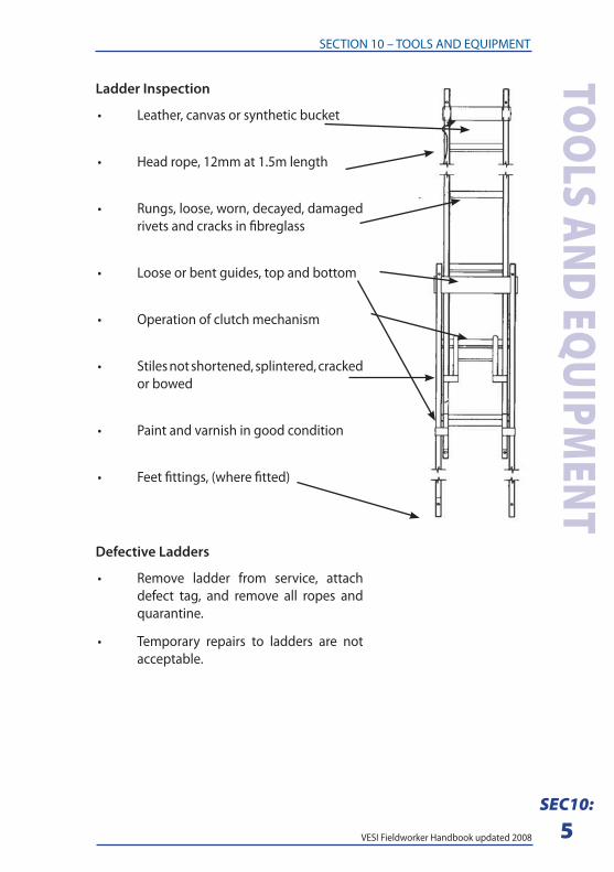
ENTLadder Inspection
• Leather, canvas or synthetic bucket
• Head rope, 12mm at 1.5m length
• Rungs, loose, worn, decayed, damaged
rivets and cracks in fi breglass
• Loose or bent guides, top and bottom
• Operation of clutch mechanism
• Stiles not shortened, splintered, cracked
or bowed
• Paint and varnish in good condition
• Feet fi ttings, (where fi tted)
Defective Ladders
• Remove ladder from service, attach
defect tag, and remove all ropes and
quarantine.
• Temporary repairs to ladders are not
acceptable.
VESI Fieldworker Handbook updated 2008
SECTION 10 – TOOLS AND EQUIPMENTTO
OLS
AND
EQ
UIPM
ENT
SEC10:
6
4. PETROL-POWERED TOOLSWhen using petrol powered equipment, employees shall:
• Be trained where appropriate.
• Turn the engine off prior to refuelling, making adjustments or
repairs.
• NOT transfer petrol from one container to another within 15
metres of the equipment’s fuel tank.
• Wear appropriate PPE (eye protection, ear muff s, gloves, etc.).
5. SAWS1. When using a powered saw, employees shall:
• Ensure the correct type of saw blade is used for the material being
cut.
• Ensure all guards are in place and fully functional.
• Keep the material fl at on the saw table.
• Wear appropriate PPE (eye protection, ear muff s, gloves, etc.).
2. When using a chainsaw, employees shall:
• Conduct pre-operating inspection of fuel, oil, and chain
inspection and tension adjustment where necessary.
• Ensure chain brakes are fi tted and in working order.
• Use all appropriate PPE including, eye & ear protection and chaps.
• Only use two-stroke fuels and appropriate bar lubricating oils.
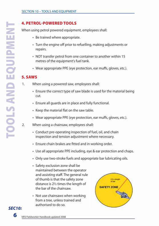
• Safety exclusion zone shall be
maintained between the operator
and assisting staff . The general rule
of thumb is that the safety zone
distance is 2½ times the length of
the bar of the chainsaw.
• Not use chainsaws when working
from a tree, unless trained and
authorised to do so.
VESI Fieldworker Handbook updated 2008
SECTION 10 – TOOLS AND EQUIPMENT
SEC10:
7
TOO
LS AND EQUIPM
ENT6. GRINDERSWhen using a grinder, employees shall:
• Ensure that the spindle speed of stationary machines does not
exceed the maximum operating speed indicated on the wheel.
• Ensure that grinding wheels are equipped with a safety washer or
fl anges, as the design requires.
• Ensure that tool rests are adjusted to a maximum of 3mm from
the wheel. Adjustments shall not be made with the wheel in
motion.
• NOT grind material on the side of a wheel.
• Apply work gradually to a cold wheel.
• NOT use a wheel that is out of round.
• Ensure guards are in place on all grinders.
• Wear appropriate PPE (eye protection, ear muff s, gloves, etc.).
7. COMPRESSED AIRWhen working with compressed air, employees shall:
• NOT use compressed air to blow dust, dirt, or any other materials
from their clothing or skin.
• NOT use conductive hoses near electrically energised equipment.
• NOT place air hoses on ladders, steps, scaff olds, or walkways so as
to create a tripping hazard.
• NOT use compressed air for cleaning purposes other than for
cleaning tools.
• NOT exceed the manufacturer’s stated safe operating pressure for
fi lters and other fi ttings.
• Wear appropriate PPE (eye protection, ear muff s, gloves, etc.).
• All compressed air hoses exceeding 10mm internal diameter shall
have a safety device at the source of supply or branch line, to shut
off or reduce pressure in the event of a hose failure.
• Air hose couplings shall be attached to the hose by means of
crimped bands. Water hose clamps shall not be used.
VESI Fieldworker Handbook updated 2008
SECTION 10 – TOOLS AND EQUIPMENTTO
OLS
AND
EQ
UIPM
ENT
SEC10:
8
8. DRILL PRESSESWhen using a drill press, employees shall:
• Securely clamp or hold in a vice or jig the item, which is to be
drilled.
• Remove chuck keys before starting any drill.
• Keep the drill press table free from excessive accumulation of drill
cuttings and long shavings.
• Wear appropriate PPE (eye protection, ear muff s, gloves, etc.).
9. HYDRAULIC PRESSESWhen using hydraulic presses/crimpers, employees shall:
• Always use them in accordance with the manufacturer’s
instructions.
• Not use electrically powered crimpers in the vicinity of live
conductors.
• Report oil leaks or crimper damage to their Team Leader.
• Not attempt repairs or maintenance in the fi eld.
10. SCAFFOLDINGWhen using scaff olding, employees shall:
• Be appropriately trained and authorised for the purpose of the
work.
• Inspect the scaff olding equipment prior to erection and replace
any defective equipment.
• Ensure scaff olding is placed on a fi rm, level surface.
• Ensure that open sides of the platform are protected by guard
rails.
• Use a ladder or equivalent means of safe access to the platform.
• NOT use ladders or makeshift devices to gain added height.
• Ensure caster brakes on rolling scaff olds are locked before any
employees climb them.
VESI Fieldworker Handbook updated 2008
SECTION 10 – TOOLS AND EQUIPMENT
SEC10:
9
TOO
LS AND EQUIPM
ENT11. WELDING – ELECTRICAL1. When using welding equipment, employees shall be appropriately
trained and authorised for the purpose of the work.
2. The primary hazards during welding are electric shock, burns, radiant
energy, toxic fumes, fi res, and explosions. Adequate precautions shall
be taken to guard against these hazards by observing the following:
• Wherever practical, safety shields or barricades shall be placed
around welding jobs, to protect others from the direct rays of an
electric arc.
• Before starting operations, all connections to the machine shall
be checked to ensure that they are properly made and in sound
condition.
• Gauntlet gloves shall be worn when welding. Outer clothing shall
be free from grease and oil. Clothing around the wrists and neck
should be fastened, and pants with cuff s turned down.
• Suitable fi re extinguishing equipment shall be immediately
available at all locations where welding is in progress.
• Adequate ventilation or approved respiratory equipment shall be
used while welding in poorly ventilated areas or when welding
zinc, brass, bronze, galvanised or lead-coated materials.
• All electric welding machines shall be properly earthed before
being operated.
• To protect the eyes, face, and body, employees engaged in
electrical welding shall wear an approved helmet, proper
protective gloves and long sleeves or welder’s sleeves.
• Employees shall wear approved eye protection when assisting
with or observing electric arc welding work.
• A welder, unless working behind a screen, shall not strike an arc
with an electrode, until nearby persons, who may be exposed to
the arc, have been given suffi cient warning.
• Cables with splices within 3 metres of the holder shall not be
used. Operators should not coil or loop welding electrode cable
around parts of their body.
• Cables with damaged insulation or exposed bare conductors shall
be replaced.
VESI Fieldworker Handbook updated 2008
SECTION 10 – TOOLS AND EQUIPMENTTO
OLS
AND
EQ
UIPM
ENT
SEC10:
10
12. WELDING – GAS1. Approved eye protection, gloves and clothing shall be worn during
all welding or cutting operations.
2. Matches or cigarette lighters shall not be used to light a torch. A torch
shall not be reignited from hot work. A fl int lighter or stationary pilot
light shall be used.
3. Hoses shall not be repaired with tape.
4. When gas welding or cutting equipment is not in use, the cylinder
valves shall be closed.
5. Flashback arrestors shall be installed on all gas welding and cutting
equipment to prevent the fl ame from entering hoses and/or
regulators. The arrestors shall be placed at the regulator and at the
hose ends.
6. Valve protection caps shall not be used for lifting cylinders from one
vertical position to another.
7. Unless cylinders are secured on a special trolley, regulators shall
be removed and valve protection caps installed prior to moving
cylinders.
8. Before a regulator is removed from a cylinder valve, the valve shall be
closed and the pressure released from the regulator.
9. All hose connections shall be clamped or otherwise secured in a
manner that will withstand, without leakage, twice the pressure to
which they are normally subjected to in service, but in no case less
than a pressure of 300psi.
10. Hoses showing leaks, burns, worn areas, or other defects, which
render them unfi t for service shall be removed from service until they
are repaired or replaced.
11. Pressure reducing regulators shall be used only for the gas and the
pressure for which they are intended.
12. Gauges on oxygen regulators shall be marked “USE NO OIL.”
VESI Fieldworker Handbook updated 2008
SECTION 10 – TOOLS AND EQUIPMENT
SEC10:
11
TOO
LS AND EQUIPM
ENT13. An acetylene cylinder valve shall not be opened more than one and
a half turns of the spindle.
14. Cylinders not having fi xed hand wheels shall have keys, handles, or
non-adjustable wrenches on the valve stems whilst they are in use.
15. Under no circumstances shall acetylene be generated, piped (except
in approved cylinder manifolds), or utilised at a pressure in excess
of 15psi. Free gaseous acetylene is potentially unstable at pressures
above 15psi and could decompose with explosive violence.
16. No welding, cutting, or other hot work shall be performed on
used drums, barrels, tanks or other containers until they have
been thoroughly cleaned so as to absolutely ensure that there is
no fl ammable materials present or any other materials that might
produce fl ammable or toxic vapours.
13. WELDING – FIRE PREVENTIONThe basic precautions that shall be used for fi re prevention in welding or
cutting work are:
• If the object to be welded or cut cannot be readily moved, all movable
fi re hazards in the vicinity shall be removed to a safe place.
• If the object to be welded or cut cannot be removed and if all the fi re
hazards cannot be removed, then guards shall be used to confi ne the
heat, sparks and slag, and to protect the immovable fi re hazards.
• If the above requirements cannot be met, then welding or cutting
operations shall not proceed.
14. GENERAL HAND TOOL SAFETY
Personal protective equipment
Use the correct PPE when using tools which, for general line work, could
include:
• rough working gloves – light or heavy duty
• safety eyewear – glasses, goggles or full face shield – tinted or clear
• hearing protection – ear muff s or plugs
• breathing protection – respirator or disposable mask
Don’t forget your regular safety gear, including wrist to ankle clothing, safety
footwear and safety helmet.
VESI Fieldworker Handbook updated 2008
SECTION 10 – TOOLS AND EQUIPMENTTO
OLS
AND
EQ
UIPM
ENT
SEC10:
12
Use tools carefully
When using hand tools:
• Always consider contact with yourself your workmate or other objects
due to unexpected tool movement.
• Cut in a direction away from your body.
• When handing a tool to another person, direct sharp points and
cutting edges away from yourself and other persons.
• When possible, only use insulated tools (e.g. screwdriver or pliers)
near electricity.
• Keep close track of tools when working at height - do not leave them
on cross-arms and other structures – a falling tool can kill!
• Don’t carry tools up a ladder in your hands or pockets - use a dilly
bag/hand line/pole bag.
• Carry and store sharp tools such as chisels in a sheath or holster –
never in your pocket.
• Don’t throw tools from one location to another, from one employee
to another or from ladders, scaff olds or EWP’s.
• Be alert for signs of strain or repetitive stress.
• Stretch and warm up before using large tools or heavy force.
• Make sure your grip and footing is secure when using large tools.
Use the correct tool for the job
Take the time to locate the correct tool – it will make the job much easier as
well as safer.
For example:
• Use a shifting spanner to fasten or undo odd sized nuts and bolts, not
as a hammer.
• Use a ring or set spanner rather than a shifting spanner.
• Use a screw driver for screwing, not chiselling.
VESI Fieldworker Handbook updated 2008
SECTION 10 – TOOLS AND EQUIPMENT
SEC10:
13
TOO
LS AND EQUIPM
ENTLook after your tools
Keep your tools, clean, lubricated and sharp - a dull or blunt blade can lead
to injury.
Don’t use broken or damaged tools – mark or tag them as unsafe to use.
Don’t use impact tools such as hammers, chisels, steel pins and punches if
they have a “mushroom” head – have the tool properly restored.
Store tools properly when you stop work.
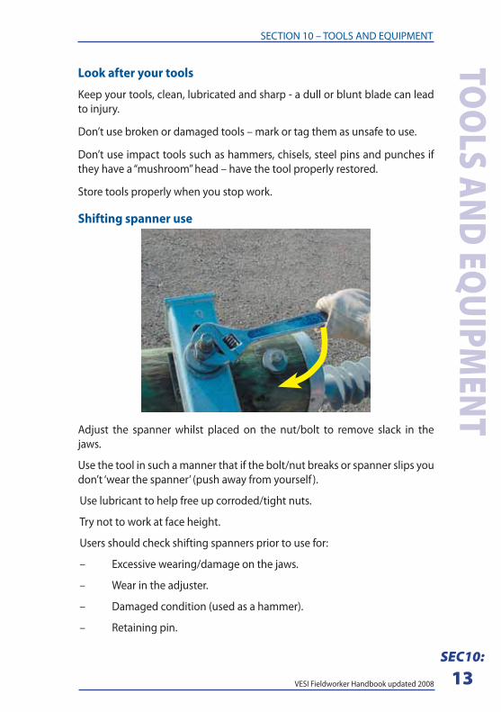
Shifting spanner use
Adjust the spanner whilst placed on the nut/bolt to remove slack in the
jaws.
Use the tool in such a manner that if the bolt/nut breaks or spanner slips you
don’t ‘wear the spanner’ (push away from yourself ).
Use lubricant to help free up corroded/tight nuts.
Try not to work at face height.
Users should check shifting spanners prior to use for:
– Excessive wearing/damage on the jaws.
– Wear in the adjuster.
– Damaged condition (used as a hammer).
– Retaining pin.
VESI Fieldworker Handbook updated 2008
SECTION 10 – TOOLS AND EQUIPMENTTO
OLS
AND
EQ
UIPM
ENT
SEC10:
14
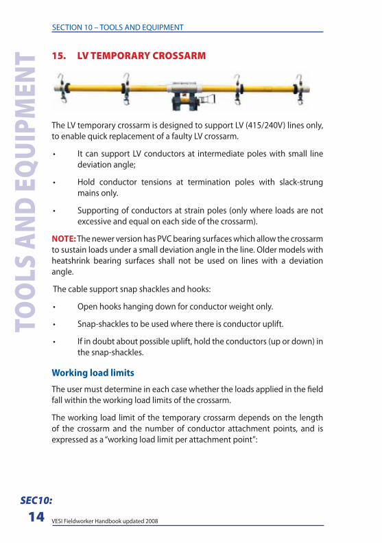
15. LV TEMPORARY CROSSARM
The LV temporary crossarm is designed to support LV (415/240V) lines only,
to enable quick replacement of a faulty LV crossarm.
• It can support LV conductors at intermediate poles with small line
deviation angle;
• Hold conductor tensions at termination poles with slack-strung
mains only.
• Supporting of conductors at strain poles (only where loads are not
excessive and equal on each side of the crossarm).
NOTE: The newer version has PVC bearing surfaces which allow the crossarm
to sustain loads under a small deviation angle in the line. Older models with
heatshrink bearing surfaces shall not be used on lines with a deviation
angle.
The cable support snap shackles and hooks:
• Open hooks hanging down for conductor weight only.
• Snap-shackles to be used where there is conductor uplift.
• If in doubt about possible uplift, hold the conductors (up or down) in
the snap-shackles.
Working load limits
The user must determine in each case whether the loads applied in the fi eld
fall within the working load limits of the crossarm.
The working load limit of the temporary crossarm depends on the length
of the crossarm and the number of conductor attachment points, and is
expressed as a “working load limit per attachment point”:
VESI Fieldworker Handbook updated 2008
SECTION 10 – TOOLS AND EQUIPMENT
SEC10:
15
TOO
LS AND EQUIPM
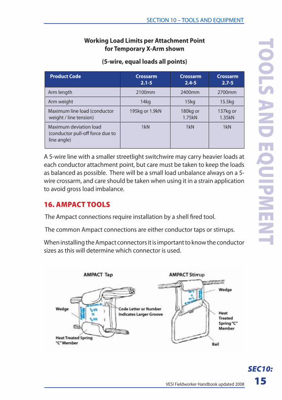
ENTWorking Load Limits per Attachment Point
for Temporary X-Arm shown
(5-wire, equal loads all points)
Product Code Crossarm
2.1-5
Crossarm
2.4-5
Crossarm
2.7-5
Arm length 2100mm 2400mm 2700mm
Arm weight 14kg 15kg 15.5kg
Maximum line load (conductor
weight / line tension)
195kg or 1.9kN 180kg or
1.75kN
137kg or
1.35kN
Maximum deviation load
(conductor pull-off force due to
line angle)
1kN 1kN 1kN
A 5-wire line with a smaller streetlight switchwire may carry heavier loads at
each conductor attachment point, but care must be taken to keep the loads
as balanced as possible. There will be a small load unbalance always on a 5-
wire crossarm, and care should be taken when using it in a strain application
to avoid gross load imbalance.
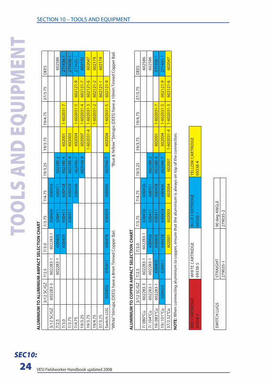
16. AMPACT TOOLSThe Ampact connections require installation by a shell fi red tool.
The common Ampact connections are either conductor taps or stirrups.
When installing the Ampact connectors it is important to know the conductor
sizes as this will determine which connector is used.
VESI Fieldworker Handbook updated 2008
SECTION 10 – TOOLS AND EQUIPMENTTO
OLS
AND
EQ
UIPM
ENT
SEC10:
16
When connecting two diff erent size conductors the wedge will have a letter
or number that indicates the larger groove (see picture above)
As per any copper to aluminium connection the aluminium cable shall
always be above the copper.
Installation
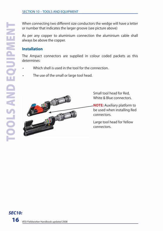
The Ampact connectors are supplied in colour coded packets as this
determines:
• Which shell is used in the tool for the connection.
• The use of the small or large tool head.
Small tool head for Red,
White & Blue connectors.
NOTE: Auxiliary platform to
be used when installing Red
connectors.
Large tool head for Yellow
connectors.
VESI Fieldworker Handbook updated 2008
SECTION 10 – TOOLS AND EQUIPMENT
SEC10:
17
TOO
LS AND EQUIPM
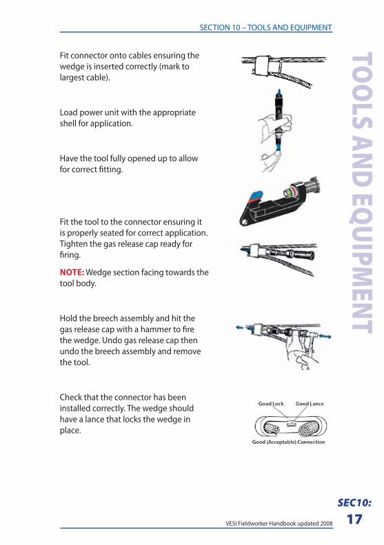
ENTFit connector onto cables ensuring the
wedge is inserted correctly (mark to
largest cable).
Load power unit with the appropriate
shell for application.
Have the tool fully opened up to allow
for correct fi tting.
Fit the tool to the connector ensuring it
is properly seated for correct application.
Tighten the gas release cap ready for
fi ring.
NOTE: Wedge section facing towards the
tool body.
Hold the breech assembly and hit the
gas release cap with a hammer to fi re
the wedge. Undo gas release cap then
undo the breech assembly and remove
the tool.
Check that the connector has been
installed correctly. The wedge should
have a lance that locks the wedge in
place.
VESI Fieldworker Handbook updated 2008
SECTION 10 – TOOLS AND EQUIPMENTTO
OLS
AND
EQ
UIPM
ENT
SEC10:
18
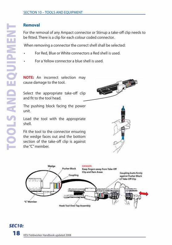
Removal
For the removal of any Ampact connector or Stirrup a take-off clip needs to
be fi tted. There is a clip for each colour coded connector.
When removing a connector the correct shell shall be selected:
• For Red, Blue or White connectors a Red shell is used.
• For a Yellow connector a blue shell is used.
NOTE: An incorrect selection may
cause damage to the tool.
Select the appropriate take-off clip
and fi t to the tool head.
The pushing block facing the power
unit.
Load the tool with the appropriate
shell.
Fit the tool to the connector ensuring
the wedge faces out and the bottom
section of the take-off clip is against
the “C” member.
VESI Fieldworker Handbook updated 2008
SECTION 10 – TOOLS AND EQUIPMENT
SEC10:
19
TOO
LS AND EQUIPM
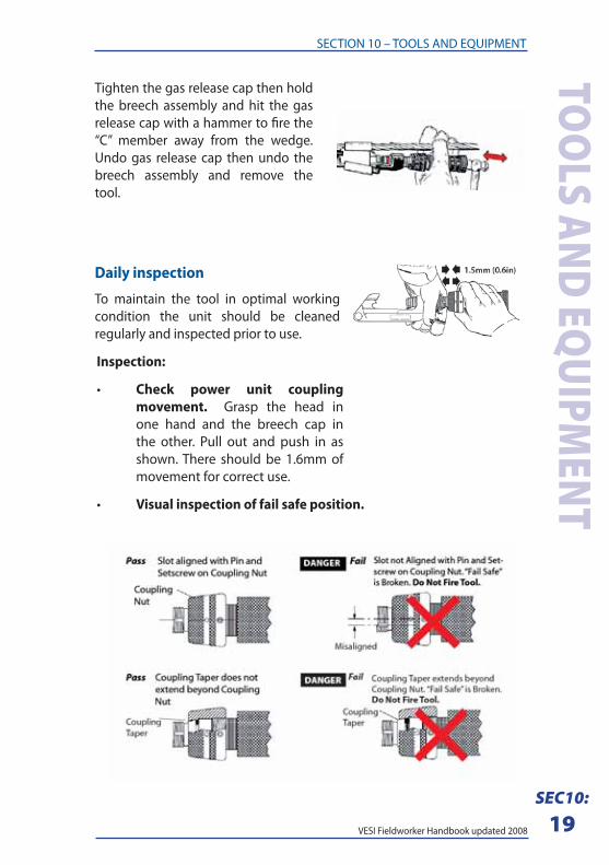
ENTTighten the gas release cap then hold
the breech assembly and hit the gas
release cap with a hammer to fi re the
“C” member away from the wedge.
Undo gas release cap then undo the
breech assembly and remove the
tool.
Daily inspection
To maintain the tool in optimal working
condition the unit should be cleaned
regularly and inspected prior to use.
Inspection:
• Check power unit coupling
movement. Grasp the head in
one hand and the breech cap in
the other. Pull out and push in as
shown. There should be 1.6mm of
movement for correct use.
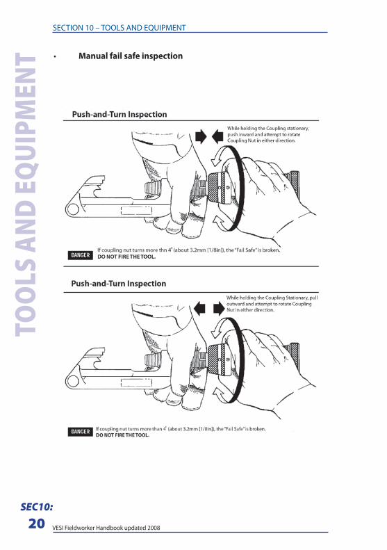
• Visual inspection of fail safe position.
VESI Fieldworker Handbook updated 2008
SECTION 10 – TOOLS AND EQUIPMENTTO
OLS
AND
EQ
UIPM
ENT
SEC10:
20
• Manual fail safe inspection
VESI Fieldworker Handbook updated 2008
SECTION 10 – TOOLS AND EQUIPMENT
SEC10:
21
TOO
LS AND EQUIPM
ENT
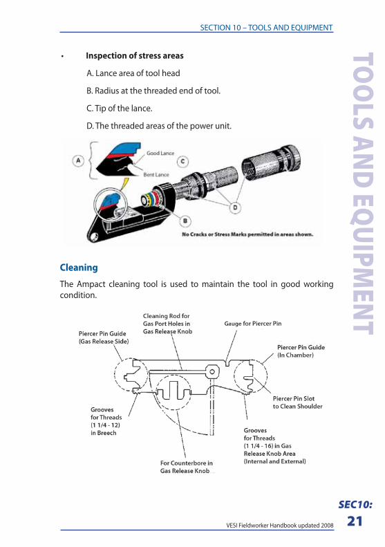
Cleaning
The Ampact cleaning tool is used to maintain the tool in good working
condition.
• Inspection of stress areas
A. Lance area of tool head
B. Radius at the threaded end of tool.
C. Tip of the lance.
D. The threaded areas of the power unit.
VESI Fieldworker Handbook updated 2008
SECTION 10 – TOOLS AND EQUIPMENTTO
OLS
AND
EQ
UIPM
ENT
SEC10:
22
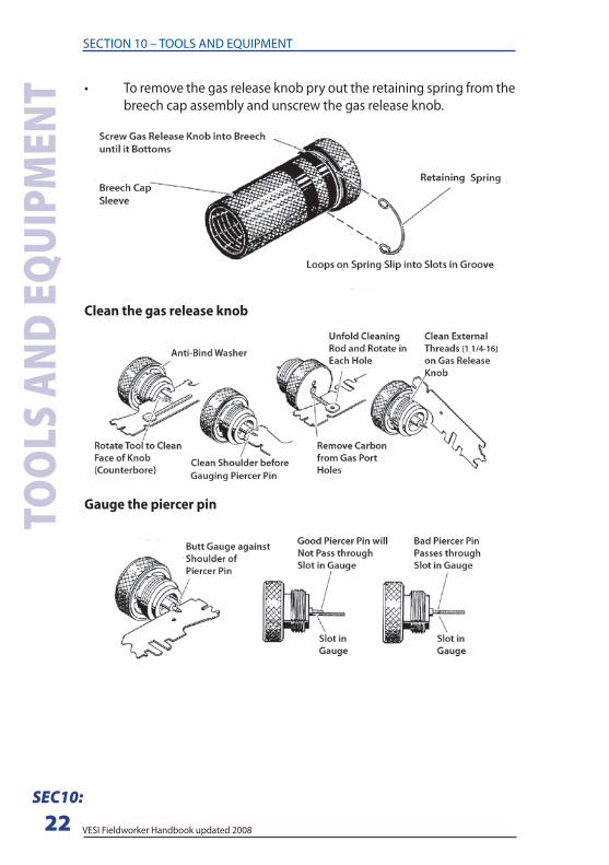
• To remove the gas release knob pry out the retaining spring from the
breech cap assembly and unscrew the gas release knob.
Clean the gas release knob
Gauge the piercer pin
VESI Fieldworker Handbook updated 2008
SECTION 10 – TOOLS AND EQUIPMENT
SEC10:
23
TOO
LS AND EQUIPM
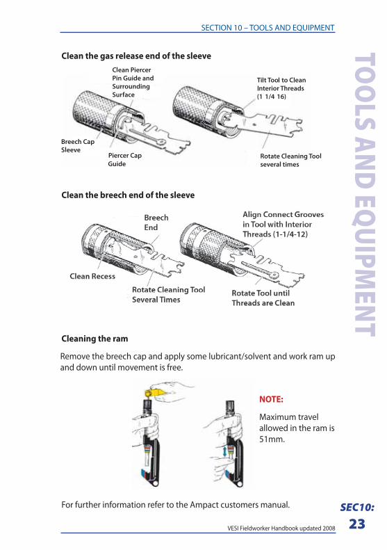
ENTClean the gas release end of the sleeve
Guide
Clean the breech end of the sleeve
Cleaning the ram
Remove the breech cap and apply some lubricant/solvent and work ram up
and down until movement is free.
For further information refer to the Ampact customers manual.
NOTE:
Maximum travel
allowed in the ram is
51mm.
VESI Fieldworker Handbook updated 2008
SECTION 10 – TOOLS AND EQUIPMENTTO
OLS
AND
EQ
UIPM
ENT
SEC10:
24
3/1
2 S
C/G
Z7
/2.5
7/3
.07
/3.7
57
/4.7
51
9/3
.25
19
/3.7
51
9/4
.75
37
/3.7
5D
EE
S
3/1
2 S
C/G
Z6
02
28
3-3
60
22
83
-16
02
28
3-1
60
04
56
60
04
56
7/2
.56
02
28
3-1
60
04
03
60
04
11
60
04
11
60
23
80
-26
02
58
6
7/3
.06
00
40
36
00
41
16
00
45
86
02
38
0-4
60
20
01
1-6
02
03
1-7
27
54
36
-1
7/3
.75
60
04
11
60
04
59
60
23
80
-46
02
00
32
75
43
6-1
7/4
.75
60
04
66
60
20
46
-76
02
00
41
-60
20
31
-56
02
12
1-9
27
54
35
-1
19
/3.2
56
02
04
6-9
60
20
07
1-6
02
03
1-4
60
21
21
-76
02
50
2
19
/3.7
51
-60
20
31
-41
-60
20
31
-36
02
12
1-6
60
20
47
19
/4.7
51
-60
20
31
-26
02
12
1-2
60
21
74
37
/3.7
56
02
12
1-1
60
21
74
Sw
itch
LU
G6
00
45
66
00
41
16
00
45
86
00
45
96
00
46
66
02
04
6-7
60
20
04
1-6
02
03
1-5
60
21
21
-9
3/1
2 S
C/G
Z7
/2.5
7/3
.07
/3.7
57
/4.7
51
9/3
.25
19
/3.7
51
9/4
.75
37
/3.7
5D
EE
S
7/.
08
0”C
u6
02
28
3-3
60
22
83
-16
02
28
3-1
60
04
56
60
04
56
60
25
86
7/.
10
4”C
u6
02
28
3-1
60
22
83
-16
00
40
36
00
41
16
00
41
16
02
38
0-2
60
25
86
19
/.0
83
”Cu
60
22
83
-16
00
40
36
00
40
36
00
41
16
00
45
86
02
38
0-4
60
20
01
1-6
02
03
1-7
27
54
36
-1
19
/.1
01
”Cu
60
04
56
60
04
11
60
04
58
60
04
59
60
04
66
60
20
46
-76
02
00
41
-60
20
31
-56
02
12
1-9
27
54
35
-1
37
/2.5
2”C
u6
02
00
16
02
00
36
02
00
46
02
00
71
-60
20
31
-41
-60
20
31
-36
02
12
1-6
60
20
47
RE
D C
AR
TR
IDG
E
69
33
8-2
WH
ITE
CA
RT
RID
GE
69
33
8-5
BLU
E C
AR
TR
IDG
E
69
33
8-1
YE
LLO
W C
AR
TR
IDG
E
69
33
8-4
SW
ITC
H L
UG
SS
TR
AIG
HT
90
de
g A
NG
LE
27
90
35
-12
79
03
5-2
“Wh
ite”
Sti
rru
ps
(DE
ES
) h
ave
a 8
mm
Tin
ne
d C
op
pe
r B
ail.
“B
lue
& Y
ello
w”
Sti
rru
ps
(DE
ES
) h
ave
a 1
0m
m T
inn
ed
Co
pp
er
Ba
il.
AL
UM
INIU
M T
O A
LU
MIN
IUM
AM
PA
CT
SE
LE
CT
ION
CH
AR
T
AL
UM
INIU
M T
O C
OP
PE
R A
MP
AC
T S
EL
EC
TIO
N C
HA
RT
NO
TE
: Wh
en
co
nn
ect
ing
alu
min
ium
to
co
pp
er,
en
sure
th
at
the
alu
min
ium
is a
lway
s o
n t
op
of
the
co
nn
ect
ion
.
VESI Fieldworker Handbook updated 2008
SECTION 10 – TOOLS AND EQUIPMENT
SEC10:
25
TOO
LS AND EQUIPM
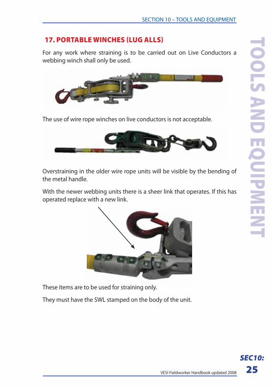
ENT 17. PORTABLE WINCHES (LUG ALLS)
For any work where straining is to be carried out on Live Conductors a
webbing winch shall only be used.
The use of wire rope winches on live conductors is not acceptable.
Overstraining in the older wire rope units will be visible by the bending of
the metal handle.
With the newer webbing units there is a sheer link that operates. If this has
operated replace with a new link.
These items are to be used for straining only.
They must have the SWL stamped on the body of the unit.
VESI Fieldworker Handbook updated 2008
SECTION 10 – TOOLS AND EQUIPMENTTO
OLS
AND
EQ
UIPM
ENT
SEC10:
26