Tools for Analysis of High Yield Drift Frames in
Combination with Moment Frames
Alexander Steven Hawkins
A project submitted to the faculty of
Brigham Young University
in partial fulfillment of the requirements for the degree of
Master of Science
Paul W. Richards, Chair
Richard J. Balling
Kevin W. Franke
Department of Civil and Environmental Engineering
Brigham Young University
April 2014
Copyright © 2014 Alexander Steven Hawkins
All Rights Reserved
ABSTRACT
Tools for Analysis of High Yield Drift Frames in
Combination with Moment Frames
Alexander Steven Hawkins
Department of Civil and Environmental Engineering
Master of Science
The purpose of this research is to prepare tools for analyzing high yield drift (HYD)
frames in combination with moment frames. The tools will enable future researchers to
efficiently model and analyze large suites of HYD, moment frame combinations.
Two main tools have been developed for the analysis of HYD, moment frame
combinations: the first is a spreadsheet to assist researchers in designing moment frames for
analysis, the second includes frame templates for modeling frames in OpenSees.
The SMRFMemberPicker spreadsheet uses a simplified analysis to design moment
frames of various strengths and geometries. The moment frame designs are summarized along
with the HYD frame information, the seismic parameters, and other building information into
OpenSees files. This tool allows for very efficient moment frame design and OpenSees analysis.
The analysis takes advantage of OpenSees templates. The templates depict a variety of
moment frames, braced frames and high yield drift frames. The SMRFMemberPicker
spreadsheet is designed to work with templates 35, 39 and 42. The OpenSees analysis outputs the
maximum story drifts as well as the residual drifts at each story. These drifts can be used to
compare frame designs of varying strengths and geometries.
Keywords: Alex Hawkins, high yield drift, HYD, moment frame, OpenSees, combination,
template
iii
TABLE OF CONTENTS
List of Tables .................................................................................................................................. v
List of Figures ............................................................................................................................... vii
1 Introduction ......................................................................................................................... 1
2 Background Literature ........................................................................................................ 3
2.1 High-Yield-Drift Steel Moment Frames for Dual Systems ............................................ 3
2.2 Evaluation of Buckling-Restrained Braced Frame Seismic Performance Considering
Reserve Strength ...................................................................................................... 3
2.3 Reducing Residual Drift of Buckling-Restrained Braced Frames as a Dual System ..... 4
3 Methods............................................................................................................................... 6
3.1 Moment Frame Design Spreadsheet ............................................................................... 6
3.1.1 Seismic Parameters Tab .................................................................................. 7
3.1.2 Building Parameters Tab ................................................................................. 7
3.1.3 P-Delta Columns Tab .................................................................................... 10
3.1.4 HYD Tab ....................................................................................................... 11
3.1.5 Other Tabs ..................................................................................................... 11
3.1.6 Generating the OpenSees Files ..................................................................... 11
3.1.7 Steel Weight .................................................................................................. 12
3.2 OpenSees Analysis Procedure ...................................................................................... 12
3.2.1 Frame Templates ........................................................................................... 12
iv
3.2.2 Static Analysis ............................................................................................... 13
3.2.3 Dynamic Analysis ......................................................................................... 13
4 Results ............................................................................................................................... 14
4.1 Designs ......................................................................................................................... 14
4.2 Drifts ............................................................................................................................. 15
4.3 Cost ............................................................................................................................... 18
4.3.1 Steel Weight .................................................................................................. 18
4.3.2 Moment Connections .................................................................................... 20
5 Conclusion and Suggestions for Future Research ............................................................ 21
References ..................................................................................................................................... 22
APPENDIX A. OpenSees Templates ........................................................................................ 23
APPENDIX B. Analysis Procedure .......................................................................................... 41
v
LIST OF TABLES
Table 1. Recommended Suite of Ground Motions ........................................................... 13
Table 2. Summary of 3 Story Frame Designs ................................................................... 15
vii
LIST OF FIGURES
Figure 1. Seismic Parameters Tab ...................................................................................... 7
Figure 2. Building Parameters Tab, part 1 .......................................................................... 8
Figure 3. Building Parameters Tab, part 2 .......................................................................... 8
Figure 4. P-Delta Columns Tab ........................................................................................ 10
Figure 5. HYD Tab ........................................................................................................... 11
Figure 6. Average Story Drifts for Each Frame Combination .......................................... 16
Figure 7. Average Residual Story Drifts for Each Frame Combination ........................... 16
Figure 8. Average Plus One Standard Deviation Story Drifts for Each Frame
Combination ...................................................................................................... 17
Figure 9. Average Plus One Standard Deviation Residual Story Drifts for Each Frame
Combination ...................................................................................................... 17
Figure 10. Weight of Steel in Structure and Story Drift for Each Frame Combination ... 19
Figure 11. Weight of Steel in Structure and Residual Story Drift for Each Frame
Combination .................................................................................................... 19
1
1 INTRODUCTION
Residual drifts in buildings that result from earthquakes can leave structures
uninhabitable and thus are very costly to owners. Dual systems can be used to reduce the residual
drifts after a seismic event. Employing a dual system is not common because owners usually
want to save on the upfront cost of a structure. High yield drift (HYD) moment frames have been
examined in combination with typical moment frames, and research shows an increase in steel
costs, but a decrease in labor costs (Miller and Richards).
The purpose of this research is to prepare tools for analyzing HYD frames in combination
with moment frames. The tools will enable future researchers to efficiently model and analyze
large suites of HYD, moment frame combinations. A potential suite of frames was defined for
this research, but the analysis was not completed because of issues outside the scope of this
project. The potential suite included moment frames of 3, 6, 9 and 20 stories, used in
combination with HYD frames of the same heights. The HYD frames have been designed with
varying capacities. Two sets of HYD frames were designed for each story height, one set has
capacity for 25% of the base shear, and one has capacity to for 50% of the base shear. Three sets
of moment frames were designed. Each story height has a moment frame designed with capacity
for 100% of the base shear, a frame designed for 75% of the base shear and a frame for 50% of
the base shear.
2
The frame combinations are analyzed using a dynamic time history analysis in OpenSees.
The issue that prevented research from being completed has to do with one of the OpenSees
templates. It is expected that upon resolving the issue, research will ready to move forward, are
researchers will be able to model and analyze any number of HYD, moment frame combinations.
3
2 BACKGROUND LITERATURE
2.1 High-Yield-Drift Steel Moment Frames for Dual Systems
Daniel J Miller, B.S.; Paul W Richards, Ph.D.
Residual drifts in buildings that result from earthquakes are expensive or impossible to
repair. Elastic analysis was used to compare high yield drift frames with 4 different
configurations to typical moment frames. The frames were examined in a 2-story application and
in a 6-story application. The different dual systems were compared based on steel cost and labor
cost. Steel cost is a function of the weight of required steel and labor cost is based on the number
of required moment connections.
Moment frames that have pinned connections at select locations are more efficient for
providing strength and high yield drift than frames with moment connections at every joint. High
yield drift frames are less efficient in steel use, but more efficient in labor costs. The upfront cost
of a HYD frame is close to the upfront cost for a typical secondary moment frame. However,
HYD frames result in significant savings in repair and replacement costs.
2.2 Evaluation of Buckling-Restrained Braced Frame Seismic Performance Considering
Reserve Strength
Christopher Ariyaratana; Larry A. Fahnestock
Buckling-restrained braced frames (BRBF) systems are effective in dissipating energy
from an earthquake, but can result in large residual drifts and soft stories. BRBF systems have
4
been modeled in dual systems with high yield drift frames and analysis shows reduction in
residual drifts up to 50%.
A prototype design was subjected to non-linear time history analysis and used as the basis
for the conclusions of the paper. Adding moment connections in conjunction with BRBF systems
show significant improvements in residual story drifts when compared to stand-alone BRBF
systems. Analyses were performed on two systems: a BRBF system with moment connections
and a dual system with a separate special moment frame. When the systems are analyzed under
the design base earthquake, the residual drifts are very close (around 0.005 radians). However,
under the maximum considered earthquake the residual drifts for the BRBF system with moment
connections are much higher (around 0.02). The most effective design for reducing residual
drifts was the dual system. The maximum considered earthquake caused residual drifts that were
much higher for the BRBF system with moment connections.
2.3 Reducing Residual Drift of Buckling-Restrained Braced Frames as a Dual System
Shawn Kiggins; Chia-Ming Uang
Buckling-restrained braced frames (BRBF) systems are effective in dissipating energy
from an earthquake, but can result in large residual drifts due to the reduction in stiffness after
the buckling-restrained braces have yielded.
Non-linear time-history analysis was performed on one frame of 3-story building and on
frame of a 6-story building. The suite of earthquakes was used to represent a site in Los Angeles.
The buildings were analyzed as a single frame using the computer program DRAIN-2DX.
The dual system only reduces maximum story drifts by 10-12%, but the residual drifts
showed significant improvement cutting drifts about in half. The real benefit of the dual systems
5
is not in the maximum story drifts, but in the residual drifts. Large maximum story drifts can
cause damage to façade and are expensive; however, maximum story drifts are fairly well
controlled in tradition lateral force resisting systems (LFRS). The lower residual drifts are the
main cost benefit for dual systems.
6
3 METHODS
Two main tools were developed to allow researchers to quickly build and model HYD,
moment frame combinations. The first tool is the moment frame design spreadsheet; it has two
main functions. First, the spreadsheet is programed to allow researchers to quickly design
moment frames. Second, the spreadsheet allows users to export .tcl files for analysis in
OpenSees. The second tool is a collection of predefined frame templates. The templates cover a
variety of braced and moment frames. Templates were also built for the HYD frames. See
APPENDIX A for figures of defined templates.
3.1 Moment Frame Design Spreadsheet
The SMRFMemberPicker spreadsheet was created in Microsoft Excel to assist in the
designing of steel special moment frames. The spreadsheet uses a simplified analysis procedure
and Visual Basic (VBA) code to size the beams and columns for special moment frames. The
simplified analysis procedure is outlined in APPENDIX B.
The spreadsheet helps choose the sections for the beams and columns of the traditional
moment frames, and exports the information to the OpenSees input file. Because of the
limitations of the analysis procedure used, the following assumptions were necessary for
reasonable results: columns are limited to either W14 shapes or deep columns where the depth of
the column is equal to the depth of the beam. The strong-column, weak-beam assumption was
followed to ensure yielding occurred in the beams not the columns.
7
3.1.1 Seismic Parameters Tab
The “Seismic Parameters” tab (Figure 1) of the SMRFMemberPicker spreadsheet follows
ASCE 7-10 and the equivalent lateral force procedure to calculate the base shear for the special
moment frame. The user should input parameters according to ASCE 7-10. The seismic weight
(W) is calculated on the “Building Parameters” tab and referenced on the “Seismic Parameters”
tab.
Figure 1. Seismic Parameters Tab
3.1.2 Building Parameters Tab
The “Building Parameters” tab (Figure 2 and Figure 3) is where the user defines the
building geometry and weight. On this tab the user specifies the number of stories and bays in
the moment frame, as well as the story height, and bay width. The user also specifies other
building parameters such as: tributary area to the moment frame, exterior wall perimeter, and
dead loads for the roof, floor and exterior wall; these parameters are used in calculating the
seismic weight of the structure. The user may use the “Populate Stories” button to quickly
populate the above mentioned parameters for each story of the moment frame. After the stories
are defined the seismic weight will be accurate and the correct base shear value will be
Ss g
S1 g R 8
Ie 1
SMs 2.1 g *Cu 1.4
SM1 1.2 g Ct 0.02
x 0.75
SDs 1.400 g Ta 1.4417
SD1 0.800 g T 2.0184
Cs 0.050
T0 0.114 s W 23654.4 kip
Ts 0.571 s Base Shear (V) 1172.0 kip
k 1.759
Cd** 5.5
Base Shear
*ASCE 7, 12.8-1
**Table 12.2-1
Site Category D
8
calculated on the “Seismic Parameters” tab. Then on the “Building Parameters” tab the
equivalent lateral force procedure is used to find the lateral force applied at each level.
Figure 2. Building Parameters Tab, part 1
Figure 3. Building Parameters Tab, part 2
# of Stories
# Bays in
the
Moment
Frame
Story
Height (in.)
Bay Width
(in.)
Trib. Area
(SQ.FT)
Perimeter
(ft.)
Roof Dead
(psf)
Floor Dead
(psf)
Partition
(psf)
Ext. Wall Dead
Load (plf) Base Fixity
Column
Depth
Beam
Depth
Base Shear
Factor
20 4 180 360 11858 308 90 90 375 30 30 100%
Story # BaysStory
Height (in.)
Bay Width
(in.)
Trib. Area
(SQ.FT)
Ext. Wall
Length (ft.)
Roof Dead
(psf)
Floor Dead
(psf)
Partition
(psf)
Ext. Wall Dead
Load (plf)
Seismic Weight
(kip)
Ext. Column
Member
Int. Column
Member
Beam
Member
1 4 180 360 11858 308 90 375 1182.72 W30X211 W30X391 W30X391
2 4 180 360 11858 308 90 375 1182.72 W30X211 W30X391 W30X391
3 4 180 360 11858 308 90 375 1182.72 W30X211 W30X391 W30X391
4 4 180 360 11858 308 90 375 1182.72 W30X211 W30X391 W30X391
5 4 180 360 11858 308 90 375 1182.72 W30X211 W30X391 W30X391
6 4 180 360 11858 308 90 375 1182.72 W30X211 W30X391 W30X391
7 4 180 360 11858 308 90 375 1182.72 W30X211 W30X391 W30X391
8 4 180 360 11858 308 90 375 1182.72 W30X211 W30X391 W30X391
9 4 180 360 11858 308 90 375 1182.72 W30X211 W30X391 W30X391
10 4 180 360 11858 308 90 375 1182.72 W30X211 W30X391 W30X391
11 4 180 360 11858 308 90 375 1182.72 W30X211 W30X391 W30X391
12 4 180 360 11858 308 90 375 1182.72 W30X211 W30X391 W30X357
13 4 180 360 11858 308 90 375 1182.72 W30X211 W30X391 W30X326
14 4 180 360 11858 308 90 375 1182.72 W30X211 W30X357 W30X326
15 4 180 360 11858 308 90 375 1182.72 W30X191 W30X357 W30X292
16 4 180 360 11858 308 90 375 1182.72 W30X191 W30X292 W30X261
17 4 180 360 11858 308 90 375 1182.72 W30X173 W30X292 W30X211
18 4 180 360 11858 308 90 375 1182.72 W30X173 W30X191 W30X173
19 4 180 360 11858 308 90 375 1182.72 W30X108 W30X191 W30X132
20 4 180 360 11858 308 90 375 1182.72 W30X108 W30X99 W30X90
Do First
Then
Populate Stories Pick Shapes Generate OS Input
Moment
Frame
Steel
Weight
(kip)
Non-LFRS
Weight
(kip)
HYD
Frame
Weight
(kip)
Total
Steel
Weight
(kip)
Allo
wabl
e
Drift
(in.)
4808.04 2578.56 7386.6 3.6
Fixed Pinned
Actual
Stiffness
Actual
Stiffness
Height
(in.)whk Cvx
Force at
Level (kips)
Force
(kips)
Target
Drift (in.)
Target Stiffness
(Kip/in.)
Target I
(in^4)
Actual
Beam I
Actual
Beam Zx
Actual Int.
Col I
Actual Int.
Col Zx
Actual
Ext. Col I
Actual Ext.
Col Zx
Ext. Col Steel
Weight
Int. Col Steel
Weight
Beam Steel
Weight
Story Mass
(k-in/s^2)
1543.2 580.0 180 ####### 0.001 1 1172 0.655 1790.5 22505 20700 1450 20700 1450 10300 751 6.33 17.595 46.92 4.4258377
1543.2 1543.2 360 ####### 0.002 3 1171 0.655 1789.3 22490 20700 1450 20700 1450 10300 751 6.33 17.595 46.92 4.4258377
1543.2 1543.2 540 ####### 0.005 5 1169 0.655 1785.3 22439 20700 1450 20700 1450 10300 751 6.33 17.595 46.92 4.4258377
1543.2 1543.2 720 ####### 0.008 9 1163 0.655 1777.1 22336 20700 1450 20700 1450 10300 751 6.33 17.595 46.92 4.4258377
1543.2 1543.2 900 ####### 0.011 13 1154 0.655 1763.5 22165 20700 1450 20700 1450 10300 751 6.33 17.595 46.92 4.4258377
1543.2 1543.2 1080 ####### 0.016 18 1141 0.655 1743.3 21912 20700 1450 20700 1450 10300 751 6.33 17.595 46.92 4.4258377
1543.2 1543.2 1260 ####### 0.020 24 1123 0.655 1715.6 21563 20700 1450 20700 1450 10300 751 6.33 17.595 46.92 4.4258377
1543.2 1543.2 1440 ####### 0.026 30 1099 0.655 1679.2 21105 20700 1450 20700 1450 10300 751 6.33 17.595 46.92 4.4258377
1543.2 1543.2 1620 ####### 0.032 37 1069 0.655 1633.1 20526 20700 1450 20700 1450 10300 751 6.33 17.595 46.92 4.4258377
1543.2 1543.2 1800 ####### 0.038 45 1032 0.655 1576.4 19814 20700 1450 20700 1450 10300 751 6.33 17.595 46.92 4.4258377
1543.2 1543.2 1980 ####### 0.045 53 987 0.655 1508.2 18957 20700 1450 20700 1450 10300 751 6.33 17.595 46.92 4.4258377
1445.4 1445.4 2160 ####### 0.052 62 934 0.655 1427.6 17943 18700 1320 20700 1450 10300 751 6.33 17.595 42.84 4.4258377
1329.5 1329.5 2340 ####### 0.060 71 873 0.655 1333.6 16762 16800 1190 20700 1450 10300 751 6.33 17.595 39.12 4.4258377
1306.5 1306.5 2520 ####### 0.069 81 802 0.655 1225.4 15402 16800 1190 18700 1320 10300 751 6.33 16.065 39.12 4.4258377
1165.9 1165.9 2700 ####### 0.078 91 721 0.655 1102.1 13853 14900 1060 18700 1320 9200 675 5.73 16.065 35.04 4.4258377
1037.3 1037.3 2880 ####### 0.087 102 630 0.655 963.0 12103 13100 943 14900 1060 9200 675 5.73 13.14 31.32 4.4258377
823.6 823.6 3060 ####### 0.097 114 528 0.655 807.1 10144 10300 751 14900 1060 8230 607 5.19 13.14 25.32 4.4258377
652.5 652.5 3240 ####### 0.107 126 415 0.655 633.6 7964 8230 607 9200 675 8230 607 5.19 8.595 20.76 4.4258377
444.8 444.8 3420 ####### 0.118 138 289 0.655 441.8 5553 5770 437 9200 675 4470 346 3.24 8.595 15.84 4.4258377
985.4 985.4 3600 ####### 0.129 151 151 0.655 230.9 1161 3610 283 3990 312 4470 346 3.24 4.455 10.8 4.4258377
9
Using the defined allowable drift and the lateral force from the equivalent lateral force
procedure, a target stiffness is calculated for each story. The approximate analysis procedure for
special moment frames (see APPENDIX B) is used, along with the assumption that the moment
of inertia for the beams is equal to the moment of inertia of the columns, to calculate an initial
target moment of inertia for the beams and columns at that story. Note that the final beams and
columns are not required to have the same moment of inertia.
After specifying the desired beam and column depths. The user may then use the “Pick
Shapes” button to size the beams and columns. The members are sized according to the strong
column-weak beam principle. The beam at each level is selected according to the following
criteria:
User specified depth
The moment of inertia for the beam must be greater than the target moment of inertia
Lightest shape that meets the above criteria
The code then selects the shape for the interior columns according the following criteria:
User specified depth
The plastic section modulus for the column must greater than the plastic section modulus
of the beam for that story
The moment of inertia for the column must be greater than or equal to the target moment
of inertia.
Lightest shape that meets the above criteria
Finally, the exterior columns are selected based on the following criteria:
10
User specified depth
The plastic section modulus for the exterior columns is greater than ½ the plastic section
modulus for interior columns.
Lightest shape that meets the above criteria
Finally, the approximate stiffnesses of each level is calculated based on the selected
shapes. The user should compare the stiffnesses to the target stiffnesses to ensure that “Pick
Shapes” button selected reasonable shapes.
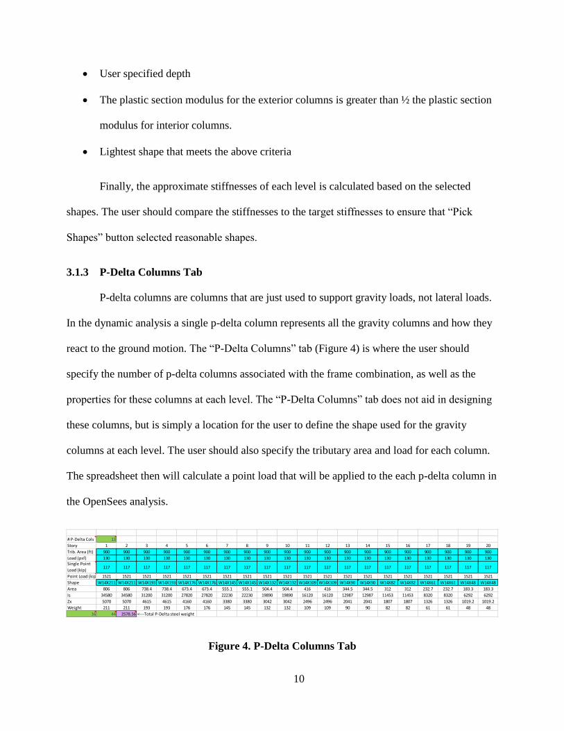
3.1.3 P-Delta Columns Tab
P-delta columns are columns that are just used to support gravity loads, not lateral loads.
In the dynamic analysis a single p-delta column represents all the gravity columns and how they
react to the ground motion. The “P-Delta Columns” tab (Figure 4) is where the user should
specify the number of p-delta columns associated with the frame combination, as well as the
properties for these columns at each level. The “P-Delta Columns” tab does not aid in designing
these columns, but is simply a location for the user to define the shape used for the gravity
columns at each level. The user should also specify the tributary area and load for each column.
The spreadsheet then will calculate a point load that will be applied to the each p-delta column in
the OpenSees analysis.
Figure 4. P-Delta Columns Tab
# P-Delta Cols 13
Story 1 2 3 4 5 6 7 8 9 10 11 12 13 14 15 16 17 18 19 20
Trib. Area (ft) 900 900 900 900 900 900 900 900 900 900 900 900 900 900 900 900 900 900 900 900
Load (psf) 130 130 130 130 130 130 130 130 130 130 130 130 130 130 130 130 130 130 130 130Single Point
Load (kip)117 117 117 117 117 117 117 117 117 117 117 117 117 117 117 117 117 117 117 117
Point Load (kip) 1521 1521 1521 1521 1521 1521 1521 1521 1521 1521 1521 1521 1521 1521 1521 1521 1521 1521 1521 1521
Shape W14X211 W14X211 W14X193 W14X193 W14X176 W14X176 W14X145 W14X145 W14X132 W14X132 W14X109 W14X109 W14X90 W14X90 W14X82 W14X82 W14X61 W14X61 W14X48 W14X48
Area 806 806 738.4 738.4 673.4 673.4 555.1 555.1 504.4 504.4 416 416 344.5 344.5 312 312 232.7 232.7 183.3 183.3
Is 34580 34580 31200 31200 27820 27820 22230 22230 19890 19890 16120 16120 12987 12987 11453 11453 8320 8320 6292 6292
Zx 5070 5070 4615 4615 4160 4160 3380 3380 3042 3042 2496 2496 2041 2041 1807 1807 1326 1326 1019.2 1019.2
Weight 211 211 193 193 176 176 145 145 132 132 109 109 90 90 82 82 61 61 48 48
16 44 2578.56 <---Total P-Delta steel weight
11
3.1.4 HYD Tab
Similar to the “P-Delta Columns” tab, the “HYD” tab (Figure 5)is a place for the user to
input the number of high yield drift frames that will be modeled in series with the moment
frames as well as the shapes that will be used for the high yield drift frames. The design for the
high yield drift frames should be performed separately and the finalized shapes for the high yield
drift frames should be entered on the “HYD” tab.
Figure 5. HYD Tab
3.1.5 Other Tabs
The “Database V14.1” tab is the AISC shapes database and is used for referencing shape
properties on previous tabs. The “Input” and “Static” tabs define the text that will be used to
create the input and static OpenSees files. These tabs are automated so the user should not need
to make any changes.
3.1.6 Generating the OpenSees Files
After the user has verified the information on the “Seismic Parameters”, “Building
Parameters”, “P-Delta Columns”, and “HYD” tabs, he or she should return to the “Building
Parameters” tab and use the “Generate OS Input” button to generate the Input.tcl and Static.tcl
files. These files will be saved in the same location as the SMRFMemberPicker spreadsheet.
# of Template 39s 1 % Base Shear 25%
HYDStories 20 20250
1 2 3 4 5 6 7 8 9 10 11 12 13 14 15 16 17 18 19 20
Columns W24X176 W24X176 W24X176 W24X176 W24X176 W24X176 W24X176 W24X176 W24X162 W24X162 W24X162 W24X162 W24X131 W24X131 W24X131 W24X131 W24X68 W24X68 W24X68 W24X68
A 51.7 51.7 51.7 51.7 51.7 51.7 51.7 51.7 47.8 47.8 47.8 47.8 38.6 38.6 38.6 38.6 20.1 20.1 20.1 20.1
I 5680 5680 5680 5680 5680 5680 5680 5680 5170 5170 5170 5170 4020 4020 4020 4020 1830 1830 1830 1830
Zx 511 511 511 511 511 511 511 511 468 468 468 468 370 370 370 370 177 177 177 177
Weight 176 176 176 176 176 176 176 176 162 162 162 162 131 131 131 131 68 68 68 68
Inside Columns W24X176 W24X176 W24X176 W24X176 W24X176 W24X176 W24X176 W24X176 W24X162 W24X162 W24X162 W24X162 W24X131 W24X131 W24X131 W24X131 W24X68 W24X68 W24X68 W24X68
A 51.7 51.7 51.7 51.7 51.7 51.7 51.7 51.7 47.8 47.8 47.8 47.8 38.6 38.6 38.6 38.6 20.1 20.1 20.1 20.1
I 479 479 479 479 479 479 479 479 443 443 443 443 340 340 340 340 70.4 70.4 70.4 70.4
Zx 115 115 115 115 115 115 115 115 105 105 105 105 81.5 81.5 81.5 81.5 24.5 24.5 24.5 24.5
Weight 176 176 176 176 176 176 176 176 162 162 162 162 131 131 131 131 68 68 68 68
Beams W24X335 W24X335 W24X335 W24X335 W24X335 W24X335 W24X335 W24X335 W24X306 W24X306 W24X306 W24X306 W24X229 W24X229 W24X229 W24X229 W24X117 W24X117 W24X68 W24X68
A 98.3 98.3 98.3 98.3 98.3 98.3 98.3 98.3 89.7 89.7 89.7 89.7 67.2 67.2 67.2 67.2 34.4 34.4 20.1 20.1
I 11900 11900 11900 11900 11900 11900 11900 11900 10700 10700 10700 10700 7650 7650 7650 7650 3540 3540 1830 1830
Zx 1020 1020 1020 1020 1020 1020 1020 1020 922 922 922 922 675 675 675 675 327 327 177 177
Weight 335 335 335 335 335 335 335 335 306 306 306 306 229 229 229 229 117 117 68 68
Total HYD Weight (kip) 1145.04
12
3.1.7 Steel Weight
The main costs in a steel moment frame structure are assumed to be the steel and the
labor intensive moment connections. The quality of each frame combination is evaluated based
on the cost and the residual drift. The SMRFMemberPicker spreadsheet has built-in tools to
calculate the approximate weight of steel for each design. The weights for the moment frame,
HYD frames, and p-delta columns are each listed on the “Building Parameters” tab.
3.2 OpenSees Analysis Procedure
The analysis for the moment frames in combination with high yield drift frames is
performed in the Open System for Earthquake Engineering Simulation (OpenSees). OpenSees is
a software developed specifically for simulating the seismic response of structural systems.
3.2.1 Frame Templates
Frame templates have been developed to make analysis using OpenSees easier. The
templates cover many typical frame shapes and orientations. See APPENDIX A for images of
the available templates. The templates were developed by a team at Brigham Young University
including Dr. Paul Richards and students: Alexander Hawkins, Mathew Steward, Brett Thomas
and Jennifer Tovar. The templates take user defined geometries and shape sizes and generate the
OpenSees models of the frames. The SMRFMemberPicker spreadsheet is designed to work
specifically with template 35, template 39 and template 42, but the spreadsheet can be altered to
work with other templates as well. Template 35 is the template used to model the moment frame,
template 39 models the HYD frame and template 42 models the p-delta columns.
The issue that prevented analysis of the collection of frame combinations is a template
issue. It is suspected that there is a bug in the code for template 39 and the analysis is aborting
before the end some of the ground motions because of it. Time and scope of this project did not
13
allow for this issue to be resolved. The tools for design and analysis are in place and upon fixing
the issue with template 39 any number of frames can be analyzed and evaluated.
3.2.2 Static Analysis
OpenSees runs static analysis on the frames according to the equivalent lateral force
procedure. The SMRFMemberPicker spreadsheet helps the user calculate the total base shear and
the percentage of the load applied at each level. OpenSees will run the static analysis and output
the story drifts. The static analysis may be used as a preliminary check of the frame designs.
3.2.3 Dynamic Analysis
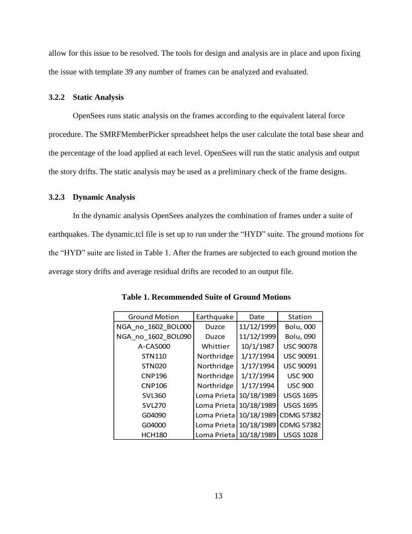
In the dynamic analysis OpenSees analyzes the combination of frames under a suite of
earthquakes. The dynamic.tcl file is set up to run under the “HYD” suite. The ground motions for
the “HYD” suite are listed in Table 1. After the frames are subjected to each ground motion the
average story drifts and average residual drifts are recoded to an output file.
Table 1. Recommended Suite of Ground Motions
Ground Motion Earthquake Date Station
NGA_no_1602_BOL000 Duzce 11/12/1999 Bolu, 000
NGA_no_1602_BOL090 Duzce 11/12/1999 Bolu, 090
A-CAS000 Whittier 10/1/1987 USC 90078
STN110 Northridge 1/17/1994 USC 90091
STN020 Northridge 1/17/1994 USC 90091
CNP196 Northridge 1/17/1994 USC 900
CNP106 Northridge 1/17/1994 USC 900
SVL360 Loma Prieta 10/18/1989 USGS 1695
SVL270 Loma Prieta 10/18/1989 USGS 1695
G04090 Loma Prieta 10/18/1989 CDMG 57382
G04000 Loma Prieta 10/18/1989 CDMG 57382
HCH180 Loma Prieta 10/18/1989 USGS 1028
14
4 RESULTS
The purpose of this research was to compare how the dual systems react with various
strength designs and at various building heights. The tools are in place for this analysis to be run,
and as soon as the issue with template 39 is resolved the frame combinations can be analyzed
and evaluated. The results shown in this section are faulty because the frames are not analyzed
for the complete ground motions. However, this section is an example of how the results might
be presented and evaluated. For demonstration purposes the faulty results for the 3 story
structure are presented here.
4.1 Designs
Six sets of 3 story frames were designed. The moment frames are 4 bays wide and 3
stories tall. The bays are 30 feet wide and the stories are 15 feet tall. The frame designs are
summarized in Table 2. Tributary area and perimeter are for a 5-bay by 5-bay square building.
Roof and floor dead loads are 90 psf and the wall dead load is 375 plf. This gives a seismic
weight of 1183 kips at each story. The site is assumed to have seismic design parameters SDS =
1.40g and SD1 = 0.80g. From ASCE 7-10 R = 8, and I = 1.
15
Table 2. Summary of 3 Story Frame Designs
4.2 Drifts
The designs can be compared based on the drifts experienced at each story during the
ground motion as well as the residual drifts after the ground motion. The drifts from each
combination of frames should be compared to the other combinations. Examples of how to
compare the drifts are given in the figures below. The average story drifts are the average of
maximum drift at each story for the suite of earthquakes. The average story residual drifts are the
drifts remaining in each story at the end of the earthquake, averaged across all the ground
motions. The average plus graphs represent the average plus one standard deviation.
16
0
1
2
3
0 % 1 % 2 % 3 % 4 % 5 % 6 %
ST
OR
Y
% OF STORY HEIGHT
AVERAGE STORY DRIFTS
50-25 50-50 75-25 75-50 100-0 100-25
Figure 6. Average Story Drifts for Each Frame Combination
0
1
2
3
0 . 0 0 % 0 . 1 0 % 0 . 2 0 % 0 . 3 0 % 0 . 4 0 % 0 . 5 0 % 0 . 6 0 %
ST
OR
Y
% OF STORY HEIGHT
AVERAGE RESIDUAL STORY DRIFTS
50-25 50-50 75-25 75-50 100-0 100-25
Figure 7. Average Residual Story Drifts for Each Frame Combination
17
0
1
2
3
0 . 0 0 % 1 . 0 0 % 2 . 0 0 % 3 . 0 0 % 4 . 0 0 % 5 . 0 0 % 6 . 0 0 % 7 . 0 0 %
ST
OR
Y
% OF STORY HEIGHT
AVERAGE PLUS STORY DRIFTS
50-25 50-50 75-25 75-50 100-0 100-25
Figure 8. Average Plus One Standard Deviation Story Drifts for Each Frame Combination
0
1
2
3
0 . 0 0 % 0 . 2 0 % 0 . 4 0 % 0 . 6 0 % 0 . 8 0 % 1 . 0 0 % 1 . 2 0 %
ST
OR
Y
% OF STORY HEIGHT
AVER AGE PLUS R ESIDUAL STORY DR IFTS
50-25 50-50 75-25 75-50 100-0 100-25
Figure 9. Average Plus One Standard Deviation Residual Story Drifts for Each Frame
Combination
18
4.3 Cost
It is apparent that there is an increase in upfront costs if a dual system is employed in a
structure. However, owners may be willing to pay more upfront if they expect the dual system to
save on recovery costs after an earthquake. In addition, some structures are critical to life safety
and need to be fully operational after a seismic event. In these cases dual systems can be
beneficial because they use the gravity framing to resist lateral loads. Researchers can use the
tools that have been developed to model HYD frames in combination with moment frames and
understand the costs. Two main costs are associated with moment frames: steel weight and
moment connections.
4.3.1 Steel Weight
Steel weight is an effective cost indicator because steel is usually sold by the pound.
Moment frames use heavy shapes to resist lateral loads through bending. However, much of the
steel in a steel building is not used in the LFRS; it is used to resist gravity loads only. By
employing a dual system engineers can take advantage of the gravity steel without significant
increase in steel weight. Figure 10 and Figure 11 show comparisons between steel weight and
drift for each of the 3 story combinations from Table 2.
19
Figure 10. Weight of Steel in Structure and Story Drift for Each Frame Combination
Figure 11. Weight of Steel in Structure and Residual Story Drift for Each Frame
Combination
50-25
50-50
75-25
75-50
100-0
100-25
900
920
940
960
980
1000
1020
1040
1060
1080
1100
1120
0% 1% 2% 3% 4% 5% 6%
Tota
l Str
uct
ure
Ste
el W
eigh
t (k
ip)
Maximum Story Drift, (% of Story Height)
50-25
50-50
75-25
75-50
100-0
100-25
900
920
940
960
980
1000
1020
1040
1060
1080
1100
1120
0.00% 0.10% 0.20% 0.30% 0.40% 0.50% 0.60%
Tota
l Str
uct
ure
Ste
el W
eigh
t (k
ip)
Maximum Residual Story Drift, (% of Story Height)
20
4.3.2 Moment Connections
Because dual systems take advantage of the gravity framing, the major cost increase for
dual systems over a single LFRS is in the moment connections. Moment connections are very
labor intensive to fabricate, and thus very expensive. One HYD frame in template 39 adds just
one moment connection every two stories. Engineers could use the tools that have been
developed to do a preliminary cost evaluation by comparing a single LFRS with a dual system.
The increase in moment connections and the associated cost could prove worthwhile in some
situations.
21
5 CONCLUSION AND SUGGESTIONS FOR FUTURE RESEARCH
The SMRFMemberPicker spreadsheet in combination with working OpenSees templates
allows researchers to efficiently model and analyzed HYD frames in combination with moment
frames. Upon resolving the issue with template 39 it is recommended that researchers investigate
a range of HYD, moment frame combinations with various heights and strengths. HYD frames in
practice are designed for 25% of the base shear force, but this may not be the most efficient
design. It is recommended that future researchers compare HYD, moment frame combinations
with varying HYD strength to pinpoint the optimal HYD design strength.
22
REFERENCES
Christopher Ariyaratana, Larry A. Fahnestock. "Evaluation of Buckling-Restrained Braced
Frame Seismic Performance Considering Reserve Strength." Engineering Structures
(2011): 77-89.
Miller, D and P Richards. "High-Yield-Drift Steel Moment Frames for Dual Systems." (2013).
Shawn Kiggins, Chia-Ming Uang. "Reducing Residual Drift of Buckling-Restrained Braced
Frames as a Dual System." Engineering Structures (2006): 1525-1532.
23
APPENDIX A. OPENSEES TEMPLATES
41
APPENDIX B. ANALYSIS PROCEDURE


![Seismic performance assessment of steel bracing systems in ... · braced RC frames and testing drift control and collapse prevention among other parameters [5]. They observed significant](https://static.documents.pub/doc/80x56/605fa7f6ded9da0351705251/seismic-performance-assessment-of-steel-bracing-systems-in-braced-rc-frames.jpg)


