46
Top-down construction – Why it is the new normal Prof. John Endicott AECOM Fellow H.K.U. and H.K.U.S.T. 4 th October 2018
Top-down construction – Why it is the new normal
Prof. John Endicott
AECOM Fellow
H.K.U. and H.K.U.S.T.
4th October 2018

Deep excavations normally require temporary walls with supports.
Steel sheet piling as deep as 15m Deeper concrete diapraghm walls
Pile walls

Cutter for diaphragm walls
Excavation for deep basements
Work commences from ground level by installing reinforced concrete walls in slurry filled trenches below ground
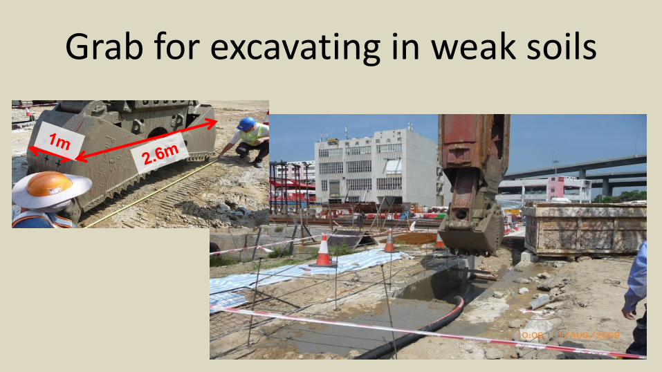
Grab for excavating in weak soils

Bottom-up sequence for constructing deep basements Stages 1 and 2
Install walls from ground level Excavate and install first strut
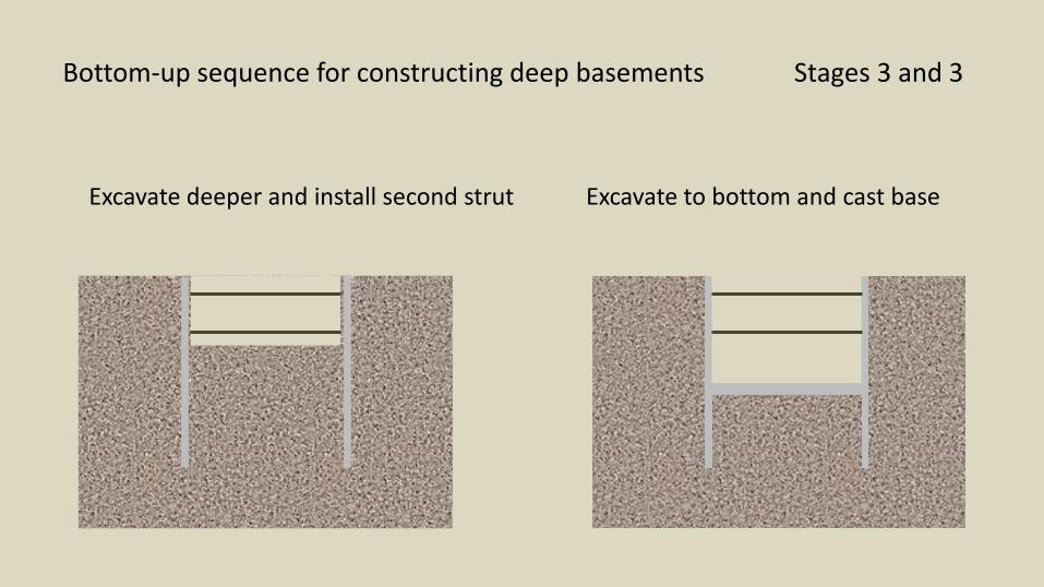
Bottom-up sequence for constructing deep basements Stages 3 and 3
Excavate deeper and install second strut Excavate to bottom and cast base

Bottom-up sequence for constructing deep basements Stages 5 and 6
Build walls up to second strut Remove strut cast slab on formwork

Bottom-up sequence for constructing deep basements Stages 7 and 8
Cast roof on formwork Remove strut and backfill

Top-down sequence for constructing deep basements Stages 1 and 2
Install walls from ground level Excavate and install first slab

Sometimes the top slab is at ground surface, sometimes it is blow ground level.
Once it is built it provides a strong level works area

Top-down sequence for constructing deep basements Stages 3 and 4
Excavate below top slab cast second slab Excavate to base and cast base slab
and backfill
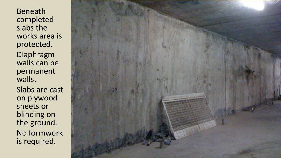
Beneath completed slabs the works area is protected.Diaphragm walls can be permanent walls.Slabs are cast on plywood sheets or blinding on the ground.No formwork is required.

Diaphragm walls are sometimes hidden by skin walls to provide a vapour barrier to accommodate slight seepage

Design Methods
PLAXIS and others programs can model the sequence in many stages.
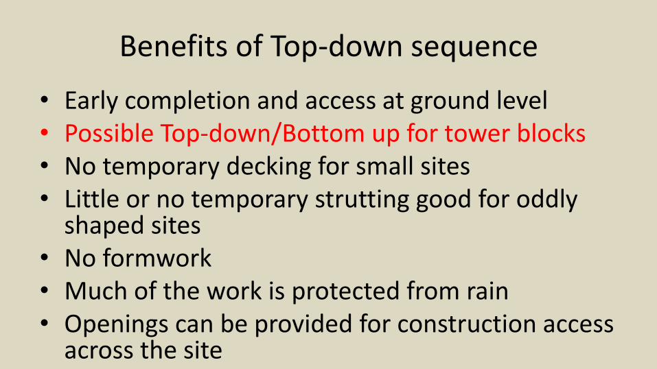
Benefits of Top-down sequence
• Early completion and access at ground level• Possible Top-down/Bottom up for tower blocks• No temporary decking for small sites• Little or no temporary strutting good for oddly
shaped sites• No formwork• Much of the work is protected from rain• Openings can be provided for construction access
across the site

Disadvantages of Top-down sequence
• Waterproofing can not be provided outside the diaphragm walls.
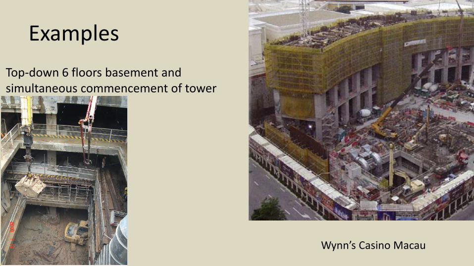
Examples
Top-down 6 floors basement and simultaneous commencement of tower
Wynn’s Casino Macau

Examples
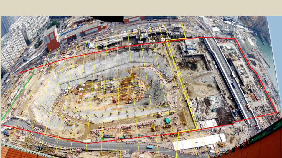
Permanent structure used for site roads on railway station site giving multiple access for hoisting muck at modest radius and though -site haul road and vehicle queuing areas.

High Speed Rail terminus underground
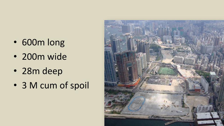
• 600m long
• 200m wide
• 28m deep
• 3 M cum of spoil

Dig a big pit and then construct bottom-up in the middle and top-down around the edges
200m

22 Presentation to EDC on 26 January 2012
Concept of reference Design
Perimeter diaphragm walls
Excavate to 27m deep (B4)
Temporary Side slopes, no struts
-5.100mPD (B2)
-25.00mPD
G.L. +5.50mPD
-6.35mPD
-21.10mPD (B4)
-6.00mPD
DIAPHRAGM WALL
SHEET PILE WALL
SHEET PILE WALLS
G.L. +5.50mPD
23 Presentation to EDC on 26 January 2012
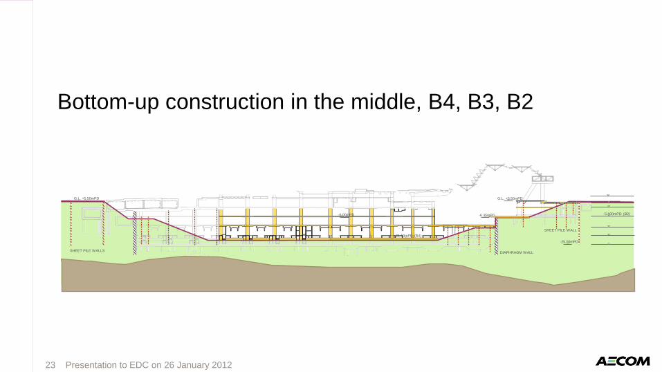
Bottom-up construction in the middle, B4, B3, B2
-5.100mPD (B2)
-25.00mPD
G.L. +5.50mPD
-6.35mPD
-21.10mPD (B4)
-6.00mPD
DIAPHRAGM WALL
SHEET PILE WALL
SHEET PILE WALLS
G.L. +5.50mPD
24 Presentation to EDC on 26 January 2012
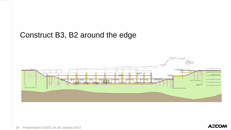
Construct B3, B2 around the edge
-5.100mPD (B2)
-25.00mPD
G.L. +5.50mPD
-6.35mPD
-21.10mPD (B4)
-6.00mPD
DIAPHRAGM WALL
SHEET PILE WALL
SHEET PILE WALLS
G.L. +5.50mPD

25 Presentation to EDC on 26 January 2012
Partial Top-down on eastern and western sides
Continue Bottom-up B1 and G/F on middle part
-5.100mPD (B2)
-25.00mPD
G.L. +5.50mPD
-6.35mPD
-21.10mPD (B4)
-6.00mPD
DIAPHRAGM WALL
SHEET PILE WALL
SHEET PILE WALLS
G.L. +5.50mPD
26 Presentation to EDC on 26 January 2012
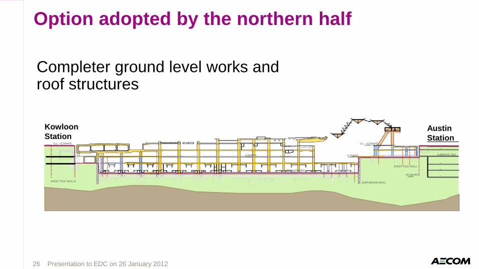
Option adopted by the northern half
Completer ground level works and roof structures
-5.100mPD (B2)
-25.00mPD
G.L. +5.50mPD
-6.35mPD
-21.10mPD (B4)
-6.00mPD
DIAPHRAGM WALL
SHEET PILE WALL
SHEET PILE WALLS
G.L. +5.50mPD
Austin
Station
Kowloon
Station

Northused reference design
South used Top-down
Two Main Contracts


Shared haul road. Top-down on left and Bottom-up on right

Bottom up core with 28m columns
Going up to ground level

An impression
Ex
ampl
eT
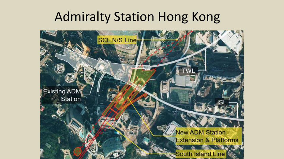
Admiralty Station Hong Kong
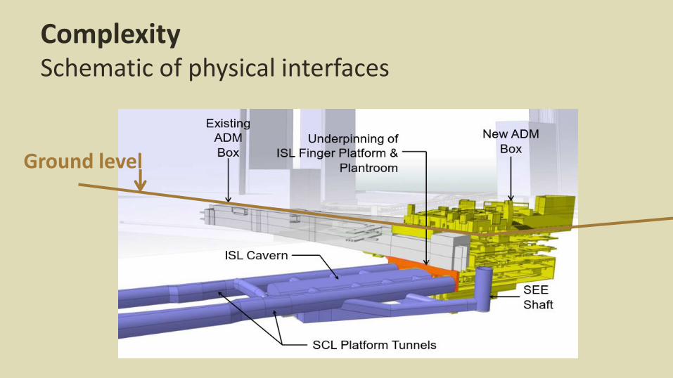
ComplexitySchematic of physical interfaces
Ground level


Top-down permanent openings for escalators and ducts
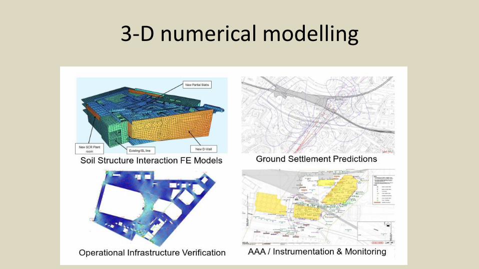
3-D numerical modelling
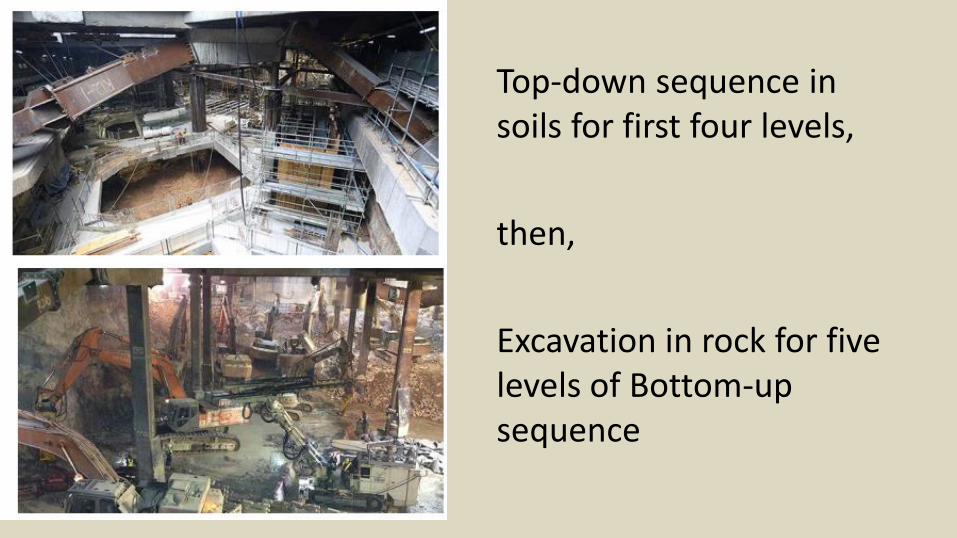
Top-down sequence in soils for first four levels,
then,
Excavation in rock for five levels of Bottom-up sequence
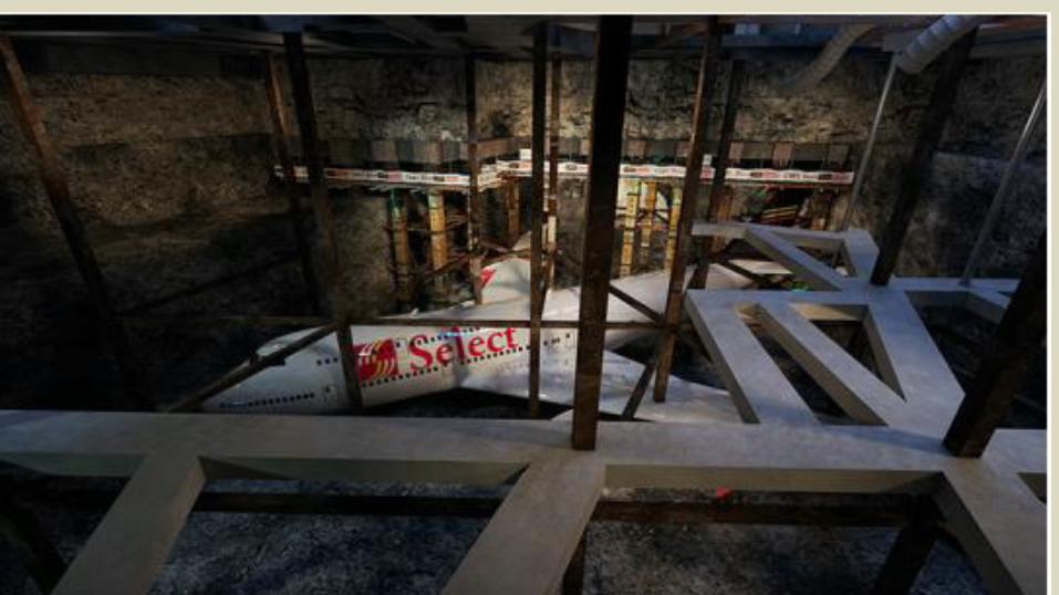

Live tracks being underpinned

Mined cavern for South island Line Concourse

Some thing to take away
Temporary sea walls in a yacht basin.
Then filled with sand.
Temporary island.
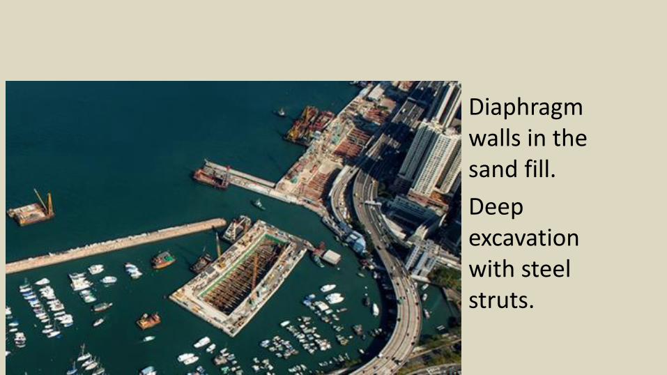
Diaphragm walls in the sand fill.
Deep excavation with steel struts.

Temporary Island, temporary walls, temporary strutting bottom up construction for six lanes of vehicular
tunnels
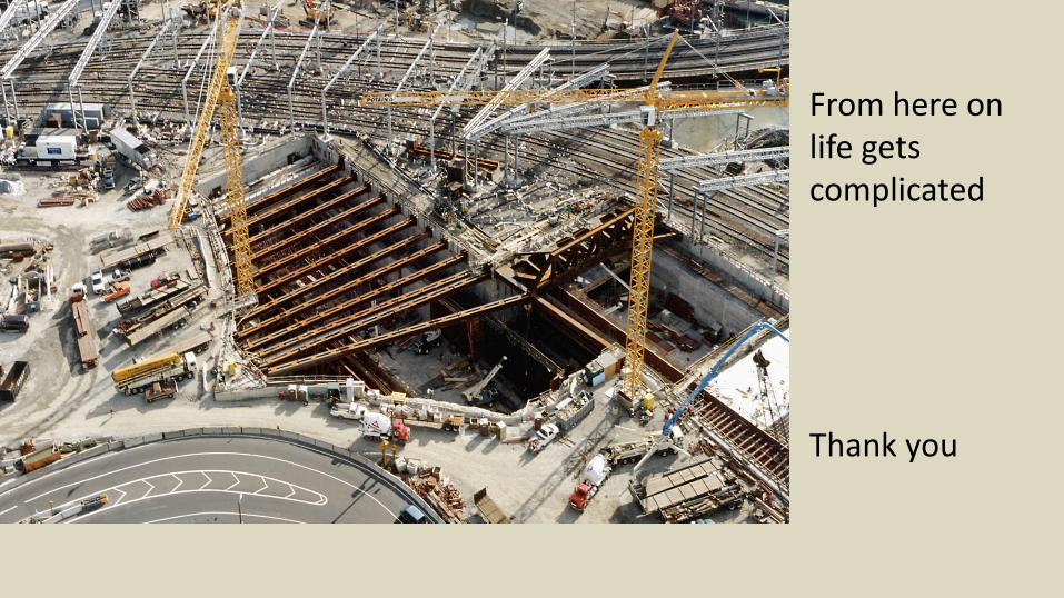
From here on life gets complicated
Thank you


