10
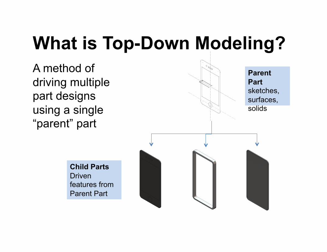
What is Top-Down Modeling? A method of driving multiple part designs using a single “parent” part
Parent Part sketches, surfaces, solids
Child Parts Driven features from Parent Part
Why Use Top-Down Design? • Maintains key relationships between parts
– Clearance and interface design details – Proper positioning in assemblies
• Rapid modifications – One change to master part can propagate to multiple
derived parts
• Multi-User assemblies – Can be used to define interfaces in between
subassemblies – Avoids circular references within assemblies
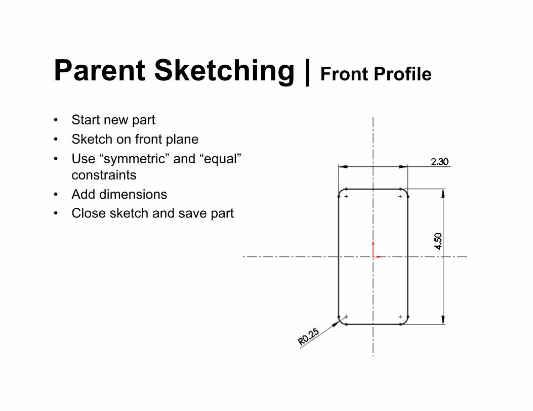
Parent Sketching | Front Profile • Start new part • Sketch on front plane • Use “symmetric” and “equal”
constraints • Add dimensions • Close sketch and save part
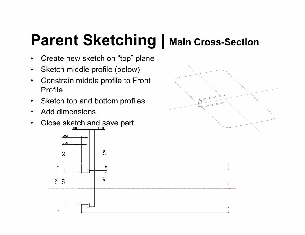
Parent Sketching | Main Cross-Section • Create new sketch on “top” plane • Sketch middle profile (below) • Constrain middle profile to Front
Profile • Sketch top and bottom profiles • Add dimensions • Close sketch and save part
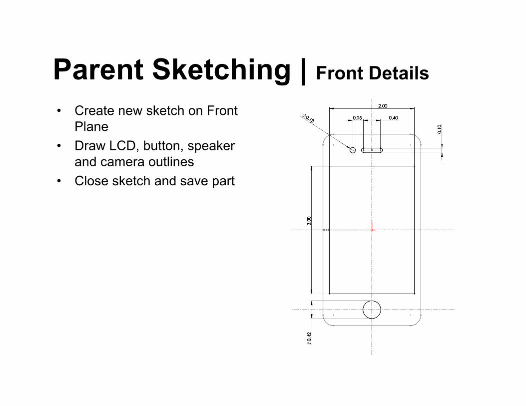
Parent Sketching | Front Details • Create new sketch on Front
Plane • Draw LCD, button, speaker
and camera outlines • Close sketch and save part
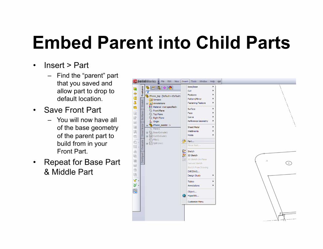
Embed Parent into Child Parts • Insert > Part
– Find the “parent” part that you saved and allow part to drop to default location.
• Save Front Part – You will now have all
of the base geometry of the parent part to build from in your Front Part.
• Repeat for Base Part & Middle Part
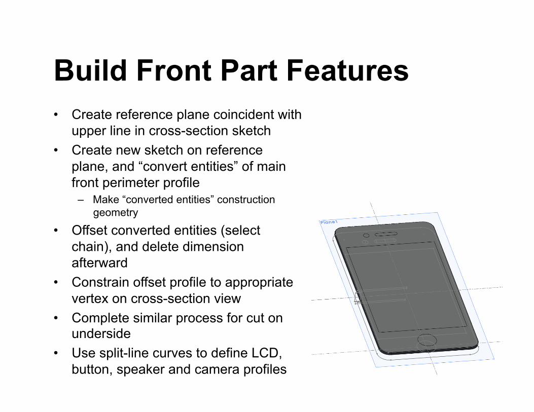
Build Front Part Features • Create reference plane coincident with
upper line in cross-section sketch • Create new sketch on reference
plane, and “convert entities” of main front perimeter profile
– Make “converted entities” construction geometry
• Offset converted entities (select chain), and delete dimension afterward
• Constrain offset profile to appropriate vertex on cross-section view
• Complete similar process for cut on underside
• Use split-line curves to define LCD, button, speaker and camera profiles
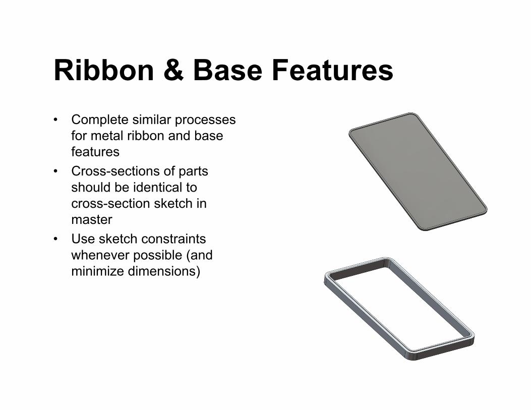
Ribbon & Base Features • Complete similar processes
for metal ribbon and base features
• Cross-sections of parts should be identical to cross-section sketch in master
• Use sketch constraints whenever possible (and minimize dimensions)
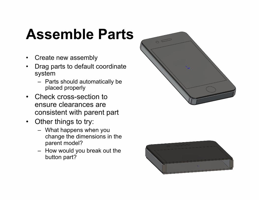
Assemble Parts • Create new assembly • Drag parts to default coordinate
system – Parts should automatically be
placed properly • Check cross-section to
ensure clearances are consistent with parent part
• Other things to try: – What happens when you
change the dimensions in the parent model?
– How would you break out the button part?