46
Top-Down Network Design Chapter Seven Selecting Switching and Routing Protocols Original slides by Cisco Press & Priscilla Oppenheimer
Top-Down Network Design
Chapter Seven
Selecting Switching and Routing Protocols
Original slides by Cisco Press & Priscilla
Oppenheimer

Selection Criteria for Switching
and Routing Protocols
• Network traffic characteristics
• Bandwidth, memory and CPU usage
• The number of peers routers or switches
supported
• The capability to adapt to changes quickly
• Support for authentication of route updates

Switching and Routing Choices
• Switching
– Layer 2 transparent bridging (switching)
– Multilayer switching
– Spanning Tree Protocol enhancements
– VLAN technologies
• Routing
– Static or dynamic
– Distance-vector and link-state protocols
– Interior and exterior
Making Decisions
• Goals must be established
• Many options should be explored
• The consequences of the decision should be
investigated
• Contingency plans should be made
• A decision table can be used

Example Decision Table
After a decision has been made, check:
•If this option is chosen, what could go wrong?
•Has this option been tried before (possibly with other customers)? If so, what
problems occurred?
•How will the customer react to this decision?
•What are the contingency plans if the customer does not approve of the
decision?

Transparent Bridging (Switching)
Tasks
• Forward frames transparently
• Learn which port to use for each MAC
address
• Flood frames when the destination unicast
address hasn’t been learned yet
• Filter frames from going out ports that
don’t include the destination address
• Flood broadcasts and multicasts

Forwarding• Store-and-forward processing
– a bridge receives a complete frame, determines which outgoing port to use, prepares the
frame for the outgoing port, calculates a cyclic redundancy check (CRC), and transmits
the frame when the medium is free on the outgoing port.
• Cut-through processing
– a switch quickly looks at the destination address (the first field in a LAN frame),
determines the outgoing port, and immediately starts sending bits to the outgoing port
– A disadvantage with cut-through processing is that it forwards illegal frames (for
example, Ethernet runts) and frames with CRC errors. On a network that is prone to runts
and errors, cut-through processing should not be used.
• Adaptive cut-through switching
– Automatically move from cut-through mode to store-and-forward mode when an error
threshold is reached.
• Parallel forwarding
– When a typical bridge is forwarding a frame from one port to another, no other frame can
be forwarded. There is only one forwarding path. A switch, on the other hand, allows
multiple, parallel forwarding paths, which means a switch can handle a high volume of
traffic more quickly than a bridge. High-end switches may support numerous
simultaneous forwarding paths, depending on the structure of the switching fabric.
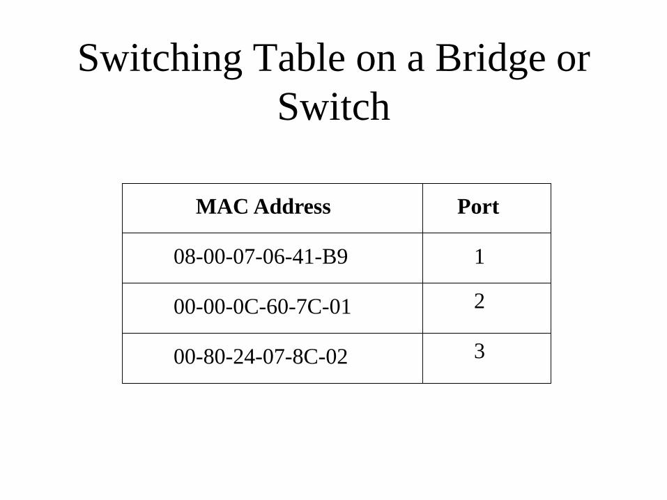
Switching Table on a Bridge or
Switch
MAC Address Port
1
2
3
08-00-07-06-41-B9
00-00-0C-60-7C-01
00-80-24-07-8C-02
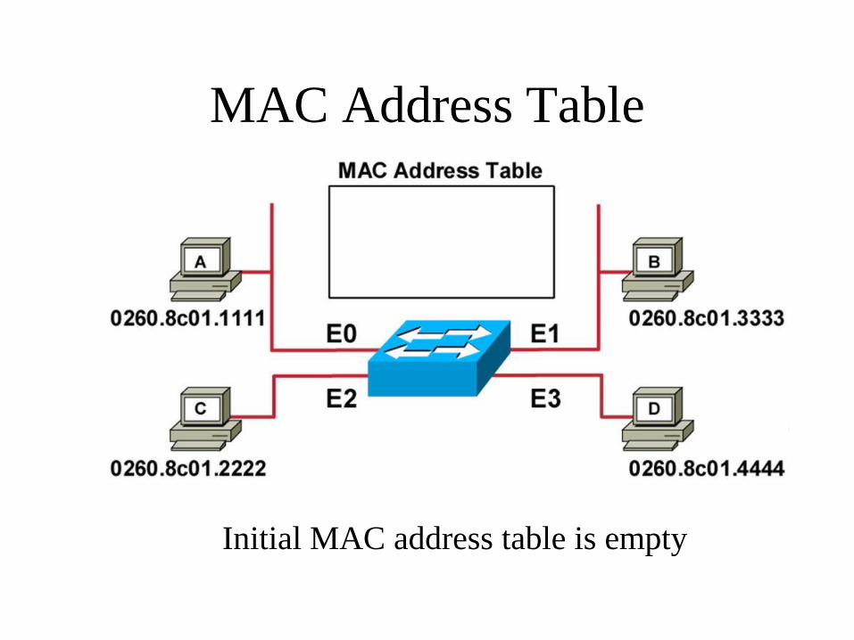
MAC Address Table
Initial MAC address table is empty

Learning Addresses
• Station A sends a frame to station C.
• Switch caches the MAC address of station A to port
E0 by learning the source address of data frames.
• The frame from station A to station C is flooded out
to all ports except port E0 (unknown unicasts are
flooded).
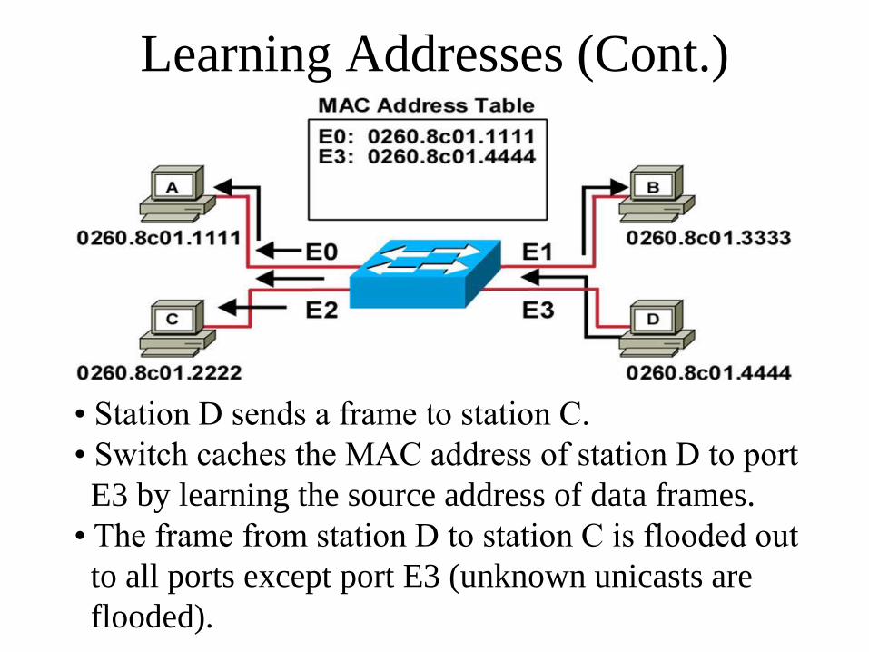
Learning Addresses (Cont.)
• Station D sends a frame to station C.
• Switch caches the MAC address of station D to port
E3 by learning the source address of data frames.
• The frame from station D to station C is flooded out
to all ports except port E3 (unknown unicasts are
flooded).

Filtering Frames
• Station A sends a frame to station C.
• Destination is known; frame is not flooded.

Multilayer Switching• Multilayer switching can refer to a switch that understands multiple layers.
• Cisco uses the term to refer to an advanced technology whereby routers (or route
processors within a switch) communicate with switches to tell the switches how to
forward frames without the router's help. There are three components:
– A route processor or router
– A switching engine
– The Multilayer Switching Protocol (MLSP)
• The route processor handles the first packet in every flow and makes a forwarding
decision based on the Layer 3 destination address.
• The switching engine tracks packets that flow to the route processor and back again,
and learns how the route processor handles the packets.
• After the first packet in a flow, the switching engine forwards the packets for that
flow without sending them to the route processor.
• MLSP is a simple protocol used by the route processor to enable multilayer
switching and to tell the switching engine to flush its Layer 3 switching table if there
is a change in the routing table or access control list configuration.
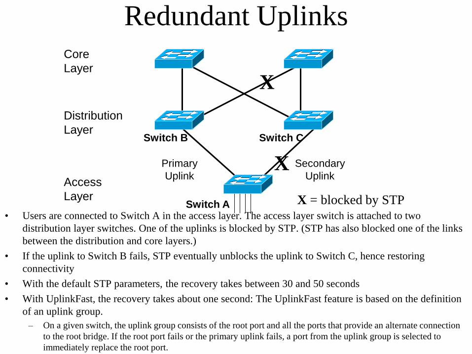
Redundant Uplinks
Access
Layer
Distribution
Layer
Core
Layer
Switch A
Switch B Switch C
Primary
Uplink
Secondary
UplinkX
X
X = blocked by STP• Users are connected to Switch A in the access layer. The access layer switch is attached to two
distribution layer switches. One of the uplinks is blocked by STP. (STP has also blocked one of the links
between the distribution and core layers.)
• If the uplink to Switch B fails, STP eventually unblocks the uplink to Switch C, hence restoring
connectivity
• With the default STP parameters, the recovery takes between 30 and 50 seconds
• With UplinkFast, the recovery takes about one second: The UplinkFast feature is based on the definition
of an uplink group.
– On a given switch, the uplink group consists of the root port and all the ports that provide an alternate connection
to the root bridge. If the root port fails or the primary uplink fails, a port from the uplink group is selected to
immediately replace the root port.

Protocols for Transporting
VLAN Information
• Inter-Switch Link (ISL)
– Tagging protocol
– Cisco proprietary
• IEEE 802.1Q
– Tagging protocol
– IEEE standard
• VLAN Trunk Protocol (VTP)
– VLAN management protocol
Selecting Routing Protocols
• They all have the same general goal:
– To share network reachability information
among routers
• They differ in many ways:
– Interior versus exterior
– Metrics supported
– Dynamic versus static and default
– Distance-vector versus link-state
– Classful versus classless
– Scalability

Interior Versus Exterior Routing
Protocols
• Interior routing protocols are used within an
autonomous system
• Exterior routing protocols are used between
autonomous systems
Autonomous system (two definitions that are often used):
“A set of routers that presents a common routing policy to the
internetwork”
“A network or set of networks that are under the administrative control
of a single entity”
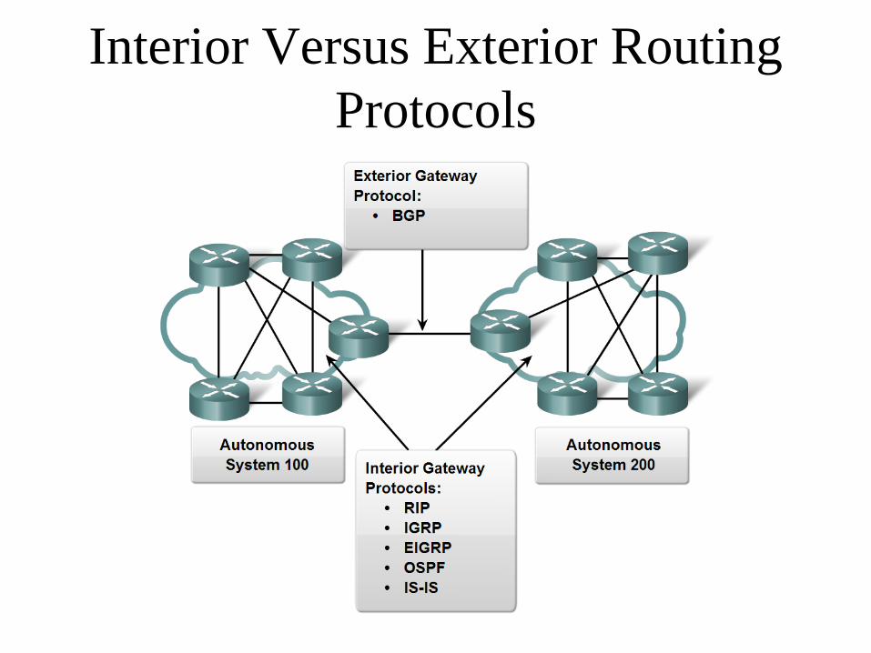
Interior Versus Exterior Routing
Protocols
Classful Routing
• Classful routing protocols do not include the subnet
mask with the route advertisement.
• Within the same network, consistency of the subnet
masks is assumed.
• Summary routes are exchanged between foreign
networks.
• Examples of classful routing protocols:
◦ RIP Version 1 (RIPv1)
◦ IGRP

Classless Routing
• Classless routing protocols include the subnet mask
with the route advertisement.
• Classless routing protocols support variable-length
subnet masking (VLSM).
• Summary routes can be manually controlled within
the network.
• Examples of classless routing protocols:
◦ RIP Version 2 (RIPv2)
◦ EIGRP
◦ OSPF
◦ IS-IS

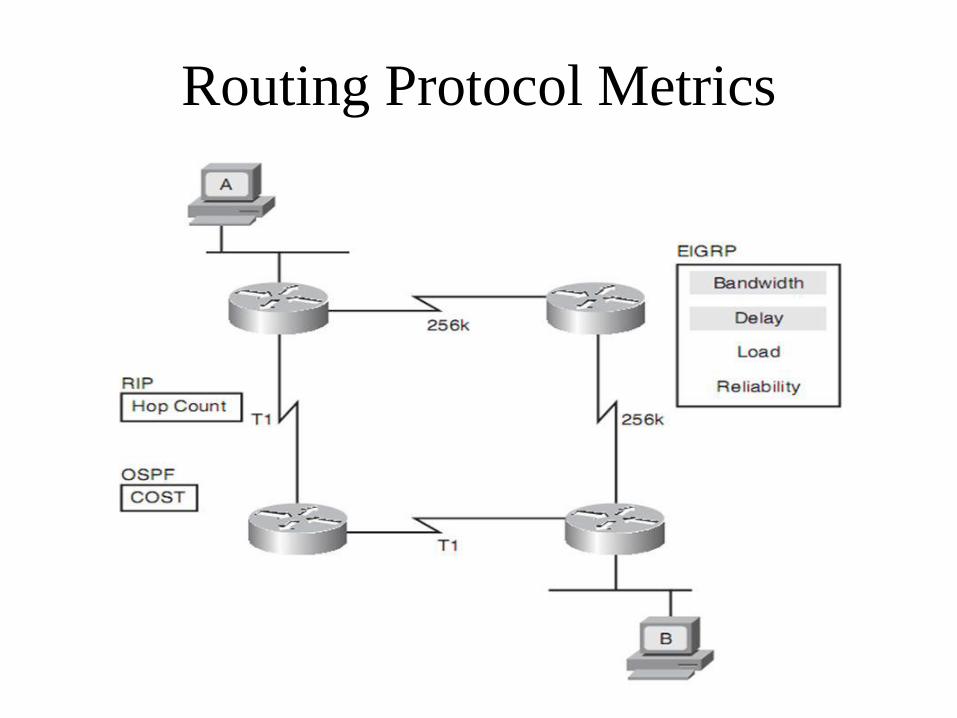
Routing Protocol Metrics
• Metric: the determining factor used by a routing algorithm to decide which route to a network is better than another
• Examples of metrics:– Bandwidth - capacity
– Delay - time
– Load - amount of network traffic
– Reliability - error rate
– Hop count - number of routers that a packet must travel through before reaching the destination network
– Cost - arbitrary value defined by the protocol or administrator
Routing Protocol Metrics
Routing Algorithms
• Static routing
– Calculated beforehand, offline
• Default routing
– “If I don’t recognize the destination, just send the
packet to Router X”
• Dynamic routing protocol
– Distance-vector algorithms
– Link-state algorithms

Static Routing Example
RouterA(config)#ip route 172.16.50.0 255.255.255.0 172.16.20.2
Send packets for subnet 50 to 172.16.20.2 (Router B)
e0 e0e0
s0 s1s0 s0
Router A Router B Router C
Host A Host CHost B
172.16.10.2 172.16.30.2 172.16.50.2
172.16.20.1 172.16.40.1
172.16.10.1 172.16.30.1 172.16.50.1
172.16.20.2 172.16.40.2

Static Routing
Advantages of static routing
-It can backup multiple interfaces/networks on
a router
-Easy to configure
-No extra resources are needed
-More secure
Disadvantages of static routing
-Network changes require manual
reconfiguration
-Does not scale well in large topologies

Default Routing Example
RouterA(config)#ip route 0.0.0.0 0.0.0.0 172.16.20.2
If it’s not local, send it to 172.16.20.2 (Router B)
e0 e0e0
s0 s1s0 s0
Router A Router B Router C
Host A Host CHost B
172.16.10.2 172.16.30.2 172.16.50.2
172.16.20.1 172.16.40.1
172.16.10.1 172.16.30.1 172.16.50.1
172.16.20.2 172.16.40.2
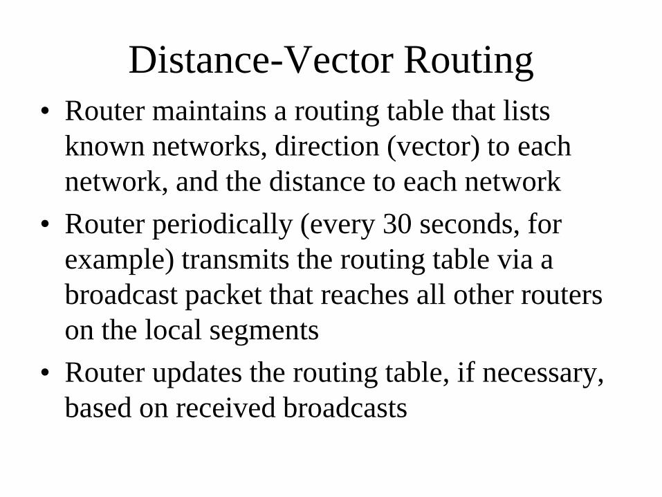
Distance-Vector Routing
• Router maintains a routing table that lists
known networks, direction (vector) to each
network, and the distance to each network
• Router periodically (every 30 seconds, for
example) transmits the routing table via a
broadcast packet that reaches all other routers
on the local segments
• Router updates the routing table, if necessary,
based on received broadcasts

Distance-Vector Routing Tables
Router A Router B
172.16.0.0 192.168.2.0
Network Distance Send To
172.16.0.0 0 Port 1
192.168.2.0 1 Router B
Network Distance Send To
192.168.2.0 0 Port 1
172.16.0.0 1 Router A
Router A’s Routing Table Router B’s Routing Table

Routing Loops with Distance-Vector Routing• When routers broadcast their routing tables, they simply send the Network and Distance
columns of the table. They do not send the Send To (Next Hop) column, which is one of the
causes of the loop problem.
• The sequence of events that can lead to a routing loop is as follows:
– Router A's connection to Network 172.16.0.0 fails.
– Router A removes Network 172.16.0.0 from its routing table.
– Based on previous announcements from Router A, Router B broadcasts its routing table saying that Router B can
reach network 172.16.0.0.
– Router A adds Network 172.16.0.0 to its routing table with a Send To (Next Hop) value of Router B and a distance
of 2.
– Router A receives a frame for a host on network 172.16.0.0.
– Router A sends the frame to Router B.
– Router B sends the frame to Router A.
• The packet loops back and forth from Router A to Router B until the IP time-to-live value
expires.
• To make matters worse, at some point Router A sends a route update saying it can get to
Network 172.16.0.0, causing Router B to update the route in its table with a distance of 3.
Both Router A and Router B continue to send route updates until finally the distance field
reaches infinity. (Routing protocols arbitrarily define a distance that means infinity. For
example, 16 means infinity for RIP.) When the distance reaches infinity, the routers remove
the route. So the protocol finally works but the convergence time is high and during that time
IP packets travel in loops.

Avoiding Routing Loops with Distance-Vector Routing
• Split-horizon
– If the protocol supports the split-horizon technique, the router sends only routes that are reachable
via other ports (equivalently, it does not send a route to a port that is reachable via the same port).
This reduces the size of the update and, more importantly, improves the accuracy of routing
information. With split horizon, a router does not tell another router information that is better
learned locally.
• Poison-reverse
– Poison-reverse messages are another way of speeding convergence and avoiding loops. With
poison-reverse, when a router learns a route from another router, it responds by sending an update
back to that router that lists the distance to the network as infinity. By doing so, the router explicitly
states that the route is not directly reachable via itself.
• Triggered updates
– Triggered updates are another advanced feature of distance-vector protocols that can speed
convergence. With triggered updates, a routing protocol announces route failures immediately.
Rather than simply waiting for the next regularly scheduled routing update and not including in the
update any routes that have failed, a router can immediately send an update. The immediate
(triggered) update lists the failed route with the distance set to infinity.
• Hold-down timer
– Most distance-vector protocols also implement a hold-down timer so that new information about a
route to a suspect network is not believed right away, in case the information is based on stale data.
Hold-down timers are a standard way to avoid loops that can happen during convergence.

Link-State Routing
• Routers send updates only when there’s a
change
• Router that detects change creates a link-state
advertisement (LSA) and sends it to neighbors
• Neighbors propagate the change to their
neighbors
• Routers update their topological database if
necessary
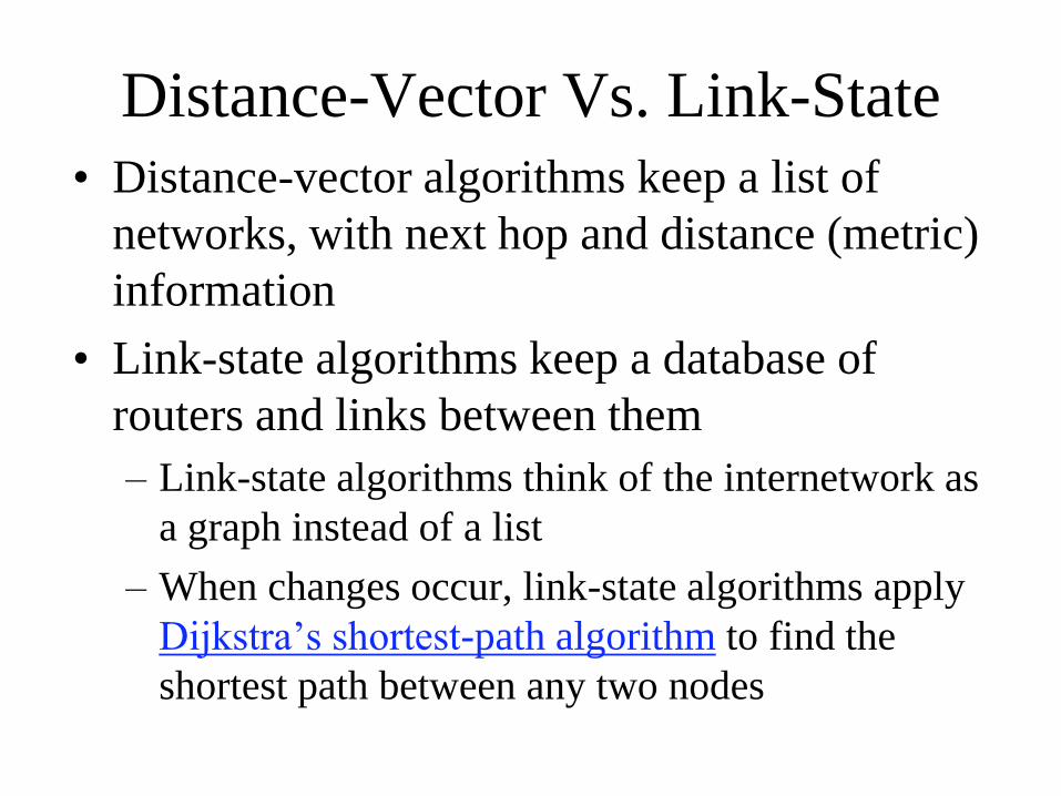
Distance-Vector Vs. Link-State
• Distance-vector algorithms keep a list of
networks, with next hop and distance (metric)
information
• Link-state algorithms keep a database of
routers and links between them
– Link-state algorithms think of the internetwork as
a graph instead of a list
– When changes occur, link-state algorithms apply
Dijkstra’s shortest-path algorithm to find the
shortest path between any two nodes
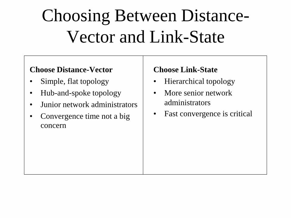
Choosing Between Distance-
Vector and Link-State
Choose Distance-Vector
• Simple, flat topology
• Hub-and-spoke topology
• Junior network administrators
• Convergence time not a big concern
Choose Link-State
• Hierarchical topology
• More senior network
administrators
• Fast convergence is critical

Dynamic IP Routing Protocols
Distance-Vector
• Routing Information Protocol
(RIP) Version 1 and 2
• Interior Gateway Routing
Protocol (IGRP)
• Enhanced IGRP
• Border Gateway Protocol (BGP)
Link-State
• Open Shortest Path First
(OSPF)
• Intermediate System-to-Intermediate System (IS-IS)
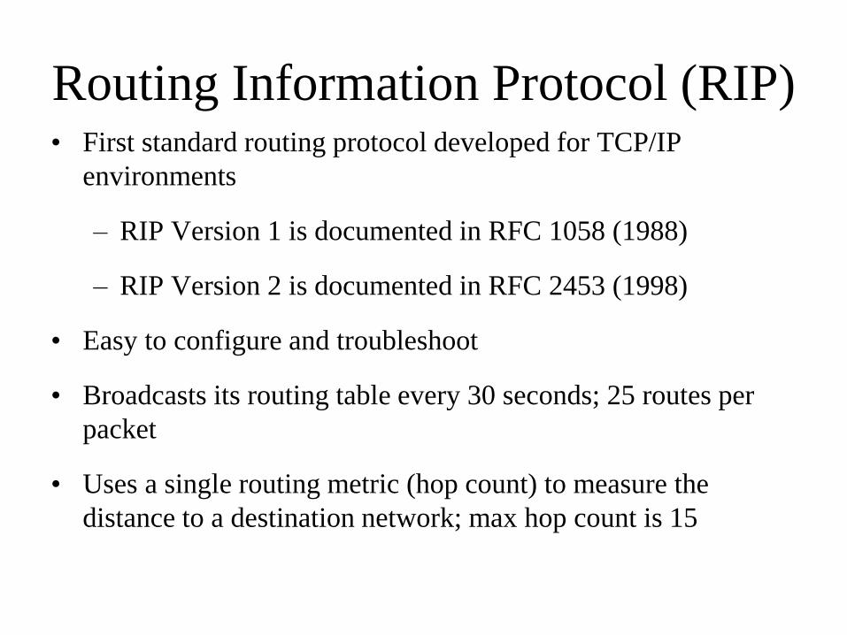
Routing Information Protocol (RIP)• First standard routing protocol developed for TCP/IP
environments
– RIP Version 1 is documented in RFC 1058 (1988)
– RIP Version 2 is documented in RFC 2453 (1998)
• Easy to configure and troubleshoot
• Broadcasts its routing table every 30 seconds; 25 routes per
packet
• Uses a single routing metric (hop count) to measure the
distance to a destination network; max hop count is 15

RIP V2 Features
• Includes the subnet mask with route updates
– Supports prefix routing (classless routing, supernetting)
– Supports variable-length subnet masking (VLSM)
• Includes simple authentication to foil crackers
sending routing updates

IGRP Solved Problems with RIP
• 15-hop limitation in RIP
– IGRP supports 255 hops
• Reliance on just one metric (hop count)
– IGRP uses bandwidth, delay, reliability, load
– (By default just uses bandwidth and delay)
• RIP's 30-second update timer
– IGRP uses 90 seconds

Open Shortest Path First (OSPF)
• Open standard, defined in RFC 2328
• Adjusts to changes quickly
• Supports very large internetworks
• Does not use a lot of bandwidth
• Authenticates protocol exchanges to meet security goals
OSPF Metric
• A single dimensionless value called cost. A network administrator assigns an OSPF cost to each router interface on the path to a network. The lower the cost, the more likely the interface is to be used to forward data traffic.
• On a Cisco router, the cost of an interface defaults to 100,000,000 divided by the bandwidth for the interface. For example, a 100-Mbps Ethernet interface has a cost of 1.

OSPF Areas Connected via Area
Border Routers (ABRs)
Area 1 Area 3Area 2
Area 0 (Backbone)
ABR ABRABR

IS-IS
• Intermediate System-to-Intermediate
System
• Link-state routing protocol
• Designed by the ISO for the OSI protocols
• Integrated IS-IS handles IP also

Border Gateway Protocol (BGP)
• Allows routers in different autonomous
systems to exchange routing information
– Exterior routing protocol
– Used on the Internet among large ISPs and major
companies
• Supports route aggregation
• Main metric is the length of the list of
autonomous system numbers, but BGP also
supports routing based on policies

Routing
table
comparison
Summary
• Ethernet switches increase the available bandwidth of a network by
creating dedicated network segments and interconnecting the
segments.
• Switches can use one of the following operating modes to transmit
frames: store and forward, cut-through, adaptive cut-through and
parallel forwarding
• Switches maintain a MAC address table to store address-to-port
mappings so it can determine the locations of connected devices.
• In a redundant topology, multiple copies of the same frame can
• arrive at the intended host, potentially causing problems with the
receiving protocol.
• If a change occurs to the network topology, STP maintains
connectivity by transitioning some blocked ports to the forwarding
state.

Summary
• Routing is the process by which an item gets from one location
to another
• A routing protocol defines the set of rules used by a router
when it communicates with neighboring routers.
• A default route is a special type of static route used for
situations when the route from a source to a destination is not
known.
• Dynamic routing relies on a routing protocol to disseminate
knowledge.
• A distance vector routing algorithm sends its entire routing
table to its neighbors. Link-state routing algorithms maintain a
complex database of topology information, which routers use
to maintain full awareness of distant routers.


