24
TOP Server: Understanding Modbus for Device Connectivity Presenter: Kevin Rutherford
| Date post: | 30-Dec-2015 |
| Category: |
Documents |
| Upload: | lucas-tillman |
| View: | 64 times |
| Download: | 3 times |

TOP Server: Understanding Modbus for
Device Connectivity
Presenter: Kevin Rutherford
Modbus Protocol TrainingAgenda
Overview Modbus Protocol Specifics
Modbus Types Modbus Terminology Modbus “Quirks” Example Modbus packets
TOP Server Modbus Suite Flexibility Supported Protocols Dealing with “Non-Standard” Modbus Devices
Live Modbus Demo Configuration Troubleshooting
Using Quick Client Using Channel Diagnostics
Questions?

What is a Protocol?
Protocols can happen at many levels and cover many things Cabling Electrical Packet structure Content of Packets Timing of Packets
Rarely does ONE protocol cover all of these things
Multiple protocols involved in making a full connection
What is a Protocol?
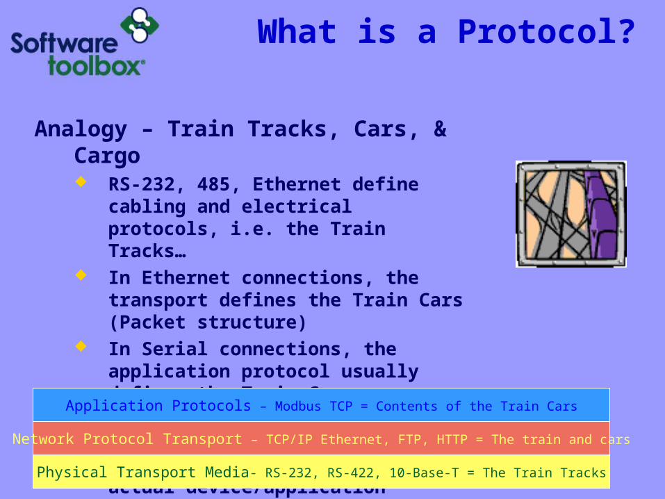
Analogy – Train Tracks, Cars, & Cargo RS-232, 485, Ethernet define cabling and
electrical protocols, i.e. the Train Tracks…
In Ethernet connections, the transport defines the Train Cars (Packet structure)
In Serial connections, the application protocol usually defines the Train Cars
What’s in the Train Cars (packets) is the Cargo – the data – which is defined by the actual device/application protocol….
Physical Transport Media- RS-232, RS-422, 10-Base-T = The Train Tracks
Network Protocol Transport – TCP/IP Ethernet, FTP, HTTP = The train and cars
Application Protocols – Modbus TCP = Contents of the Train Cars

Parts of a Typical Application Protocol
Many application protocols use some or all of these in their structures: Header/start characters Target Device ID Function Code, Sub-Function Codes Data Length Data Checksum/error checking Termination character
Data section usually contains Read: Memory type, start location, length, or multiple
locations in some protocols Write: Memory type & location to write, size to write,
actual data to write Data contents is usually driven by what Function Code or
Sub-Function Codes are used in the request Data is OFTEN communicated in Hex – Base 16!!!!
Modbus – Used Everywhere!
Schneider/Modicon/Telemecanique PLCs Nearly every other PLC brand offers built-in
Modbus or a Modbus option module Electrical transmission & distribution control &
monitoring equipment Water/wastewater control equipment Temperature controllers AC Variable Speed Drives Servo Drives Pick a device – it just might support Modbus When in doubt – find out – is Modbus a choice
on the hardware?

Modbus Types
Serial – RS-232/422/485 electrical protocol Two possible transmission modes:
Modbus RTU Modbus ASCII
Proprietary – Vendor specific electrical protocol Modbus Plus
Ethernet – standard TCP/IP Ethernet electrical +transport Modbus TCP or Modbus Ethernet Ethernet Encapsulated Modbus RTU or ASCII
Gateway Devices Ethernet or Modbus Plus Modbus RTU or ASCII serial on other side Multiple serial devices on downstream side

Modbus Terminology
Memory Types & Addressing Input coils = Digital inputs
1xxxxx address type 0/1 values Boolean data type
Output Coils = Digital outputs 0xxxxx address type 0/1 values Boolean data type
Input Registers = Analog inputs 3xxxxx address type 16-bit registers 32-bit data types use two consecutive registers
Holding (Output) Registers = Analog outputs 4xxxxx address type 16-bit registers 32-bit data types use two consecutive registers

Modbus Terminology
Read/Write Access Read Only: Input registers & Input Coils Read/Write: Output Coils and Holding Registers
Addressing – 5 or 6 digits Original Modbus was 5 digits – i.e. 40001 As PLC memories grew, went to 6, i.e. 400001
Offset Modbus address offset is all digits after the first digit
identify which memory type the address is Can be 0 or 1 based Pointer that specifies where into that memory type to
go and start getting data or writing data

Modbus Terminology
Modbus Node Address Used with serial devices Each device on serial connection has unique
ID Slave ID values = 1 to 247 Master’s don’t have a Node address
Modbus Function Codes Used by Modbus Masters to tell a Modbus
Slave what they want it to do Read or Write? Memory Type? Single item or Multiple Items in a Transaction

Modbus Terminology
Common Modbus Function Codes 01 – Read Coils (output coils), 0xxxxx memory 02 – Read Discrete Inputs (input coils), 1xxxxx
memory 03 – Read Holding Registers, 4xxxxx memory 04 – Read Input Registers, 3xxxxx memory 05 – Write Single coil (outputs), 0xxxxx memory 06 – Write single Holding Register, 4xxxxx
memory 15 (0x0F) – Write multiple coils (outputs) 16 (0x10) – Write multiple Holding Registers

Modbus Terminology
Modbus Exception Codes Used by slaves to tell Master what it
did not like about a request Examples:
02 - Bad memory address 01 - I don’t understand this function code 0x0B - Slave didn’t respond – gateway
devices

Common Modbus Quirks
Data Byte Ordering 32 bit data type word order 64 bit data type Dword order Byte order within words
Addressing – 0 or 1 based Function Code support Use of user definable function codes Non-Modicon use of memory type + offset for
addressing in documentation confusing
Modbus RTU Packet Framing
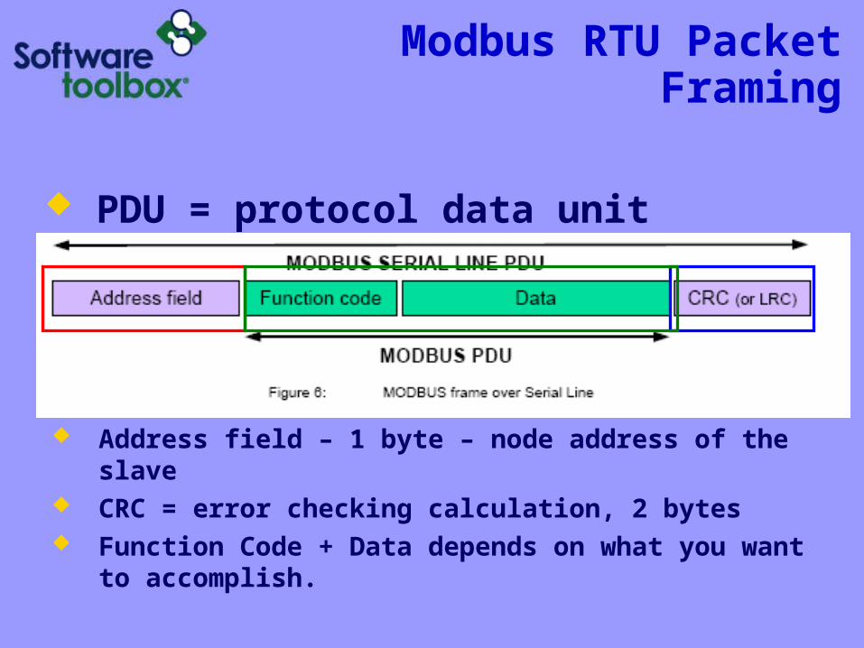
PDU = protocol data unit
Address field – 1 byte – node address of the slave CRC = error checking calculation, 2 bytes Function Code + Data depends on what you want to
accomplish.

Modbus Packet FormatModbus RTU
A MODBUS message is placed by Modbus Master into a serial frame that has a known beginning and ending point.
This is an amount of time indicating to devices that receive a new frame to begin at the start of the message, and to know when the message is completed.
In RTU mode, message frames are separated by a silent interval of at least 3.5 character times. Character time= time to send one byte @ chosen baud rate

Modbus RTU ExampleRead Holding Registers 108-110
from Slave Node 01 Transmit: TX: 01 03 00 6B 00 03 xx xx Receive: RX: 01 03 06 02 2B 00 00 00 64 xx xx
IMPORTANT
Notice:
1. Request is in # of registers
2. Response is in # of bytes
3. 1 Register = 2 bytes
xx xx = 2 byte checksum

Modbus RTU ExampleWrite Single Holding Register 2 with
value of 3 on Slave Node 1 Transmit: TX: 01 06 00 01 00 03 xx xx Receive: RX: 01 06 00 01 00 03 xx xx
xx xx = 2 byte checksum

Modbus RTU ExampleException Response
Master asks for memory address that doesn’t exist in the slave
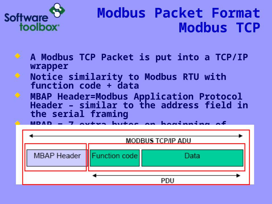
Modbus Packet FormatModbus TCP
A Modbus TCP Packet is put into a TCP/IP wrapper Notice similarity to Modbus RTU with function code
+ data MBAP Header=Modbus Application Protocol Header
– similar to the address field in the serial framing MBAP = 7 extra bytes on beginning of transmission

Modbus TCP MBAP HeaderContents
Unit identifier used when using bridging to downstream serial devices. 0 = no bridging being used
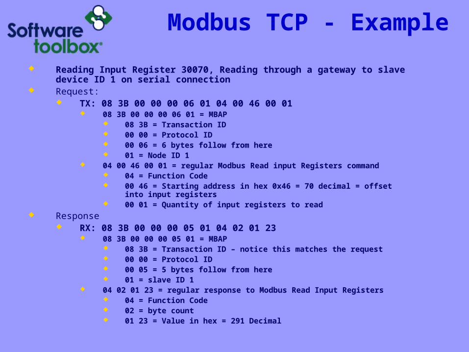
Modbus TCP - Example
Reading Input Register 30070, Reading through a gateway to slave device ID 1 on serial connection
Request: TX: 08 3B 00 00 00 06 01 04 00 46 00 01
08 3B 00 00 00 06 01 = MBAP 08 3B = Transaction ID 00 00 = Protocol ID 00 06 = 6 bytes follow from here 01 = Node ID 1
04 00 46 00 01 = regular Modbus Read input Registers command 04 = Function Code 00 46 = Starting address in hex 0x46 = 70 decimal = offset into input
registers 00 01 = Quantity of input registers to read
Response RX: 08 3B 00 00 00 05 01 04 02 01 23
08 3B 00 00 00 05 01 = MBAP 08 3B = Transaction ID – notice this matches the request 00 00 = Protocol ID 00 05 = 5 bytes follow from here 01 = slave ID 1
04 02 01 23 = regular response to Modbus Read Input Registers 04 = Function Code 02 = byte count 01 23 = Value in hex = 291 Decimal

TOP Server Modbus Suite Flexibility
Protocols Supported Modbus RTU Serial Master and Slave Modbus ASCII Master Modbus Plus Modbus TCP Ethernet Master and Slave
Flexible Settings for Non-Standard Modbus Zero or One-Based Addressing Holding Register Bit Mask Writes Specifying Function Code for Writes Data order manipulation
Live Demo
Overview Modbus Protocol Specifics
Modbus Types Modbus Terminology Modbus “Quirks” Example Modbus packets
TOP Server Modbus Suite Flexibility Supported Protocols Dealing with “Non-Standard” Modbus Devices
Live Modbus Demo Configuration Troubleshooting
Using Quick Client Using Channel Diagnostics
Questions?

Questions?
Questions later? Kevin Rutherford
[email protected] 704-849-2773 x1326
TOP Server Modbus Suite (Info / Free Demo) http://www.toolboxopc.com/html/modbussuite.html
Other learning opportunities Visit www.softwaretoolbox.com/webinars


