42
Malaysian Institute of Aviation Technology Revision 00 Issue 01 Module 5.4 DIGITAL TECH (MECH) AKD 21102 CHAPTER 7 FIBER OPTIC
| Date post: | 15-Jul-2015 |
| Category: |
Engineering |
| Upload: | bai-haqi |
| View: | 174 times |
| Download: | 0 times |
Malaysian Inst itute of Aviat ion Technology
Revision 00 Issue 01 Module 5.4
DIGITAL TECH (MECH)AKD 21102
CHAPTER 7
FIBER OPTIC
Malaysian Inst itute of Aviat ion Technology
• Data transmission over electrical wire propagation• Fiber optic data bus • Fiber optic related terms• Advantages and disadvantages of fiber optic• Terminations: cleaving, stripping, splicing and
termination losses• Couplers, control terminals, remote terminals • Application of fiber optics in aircraft system
Revision 00 Issue 01 Module 5.4
LEARNING OUTCOME
Malaysian Inst itute of Aviat ion Technology
Revision 00 Issue 01 Module 5.10
Malaysian Institute of Aviation Technology
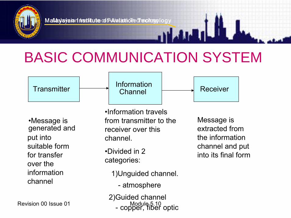
BASIC COMMUNICATION SYSTEM
•Information travels •Message is generated and
from transmitter to the Message is receiver over this extracted from
put into channel. the information suitable form channel and put
•Divided in 2 for transfer into its final form categories: over the
information 1)Unguided channel. channel - atmosphere
2)Guided channel
- copper, fiber optic
Transmitter InformationChannel Receiver
Malaysian Inst itute of Aviat ion Technology
Revision 00 Issue 01 Module 5.10
Malaysian Institute of Aviation Technology
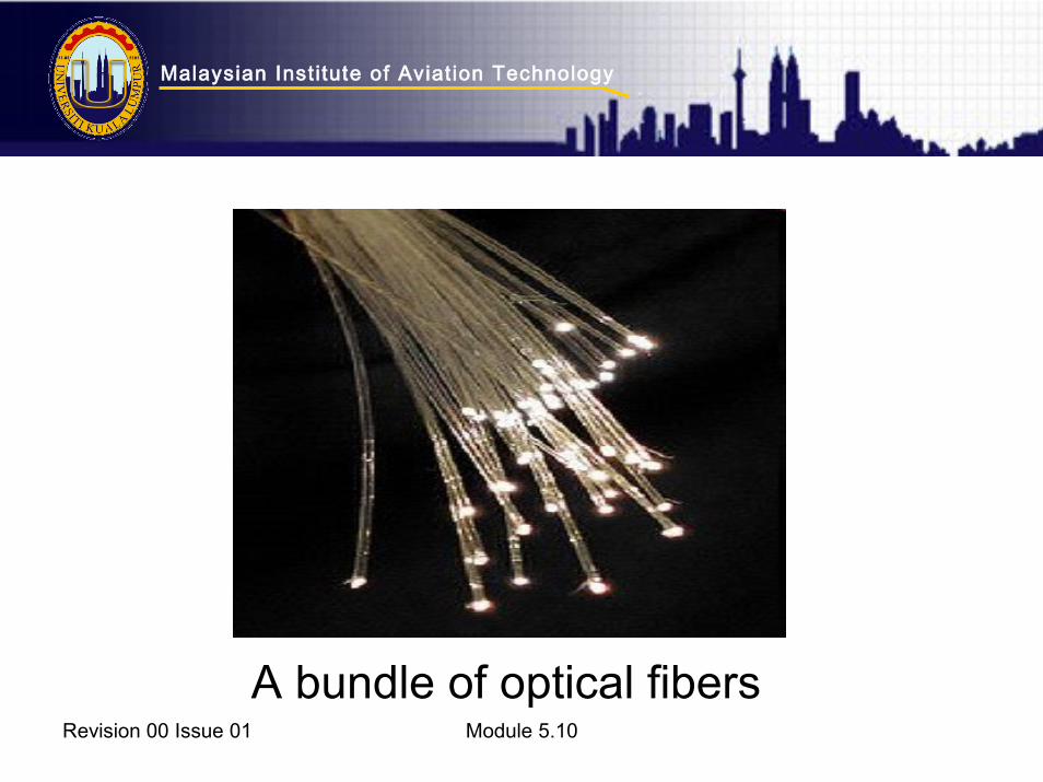
• Fiber optics (optical fibers) are long, thin strands of very pure glass about the diameter of a human hair. They are arranged in bundles called optical cables
• Used to transmit high-speed transmission of data using light over long distances.
• Transmission depend on the opticalproperty of total internal reflection
WHAT IS FIBER OPTIC?
Malaysian Inst itute of Aviat ion Technology
Revision 00 Issue 01 Module 5.10
A bundle of optical fibers

Malaysian Inst itute of Aviat ion Technology
Revision 00 Issue 01 Module 5.10
STRUCTURE
Malaysian Inst itute of Aviat ion Technology
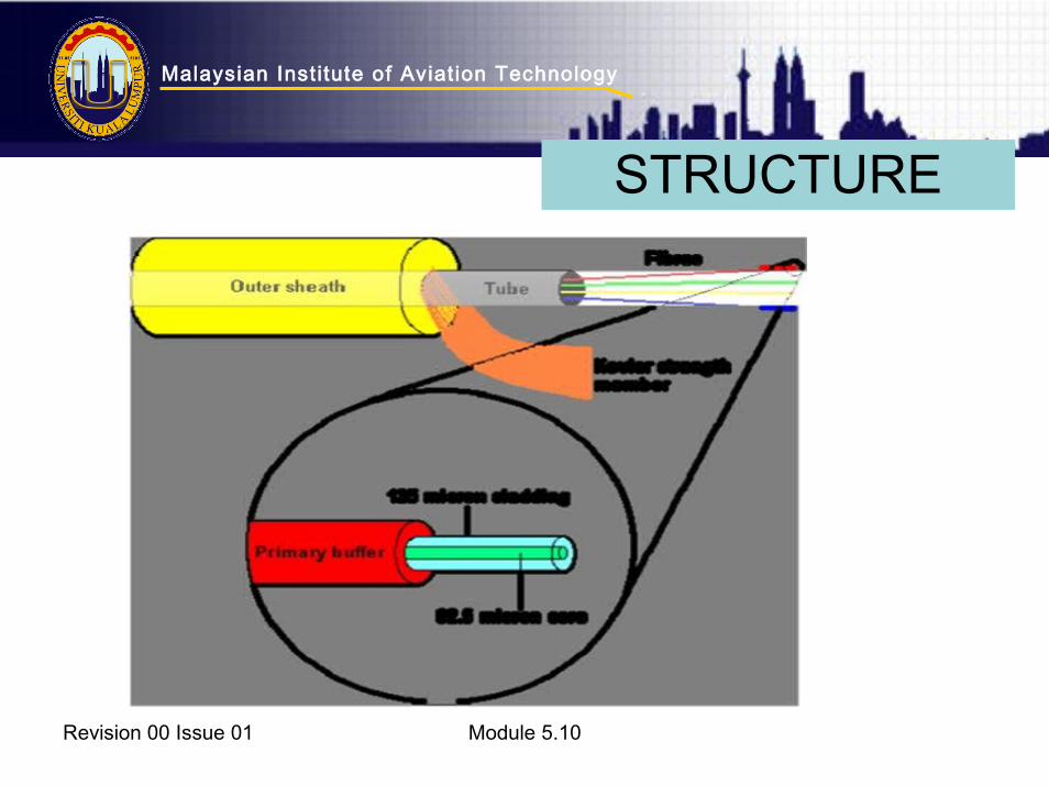
• Core - Thin glass centre of the fiber where the light travels
• Cladding - Outer optical material surrounding the core that reflects the light back into the core • Buffer coating - Plastic coating that protects the fiber from damage and moisture • Hundreds or thousands of these optical fiber are
arranged in bundles in optical cables. The bundles are protected by the cable's outer covering, called a jacket
Revision 00 Issue 01 Module 5.4
STRUCTURE
Malaysian Inst itute of Aviat ion Technology
Revision 00 Issue 01 Module 5.10
STRUCTURE
Malaysian Inst itute of Aviat ion Technology
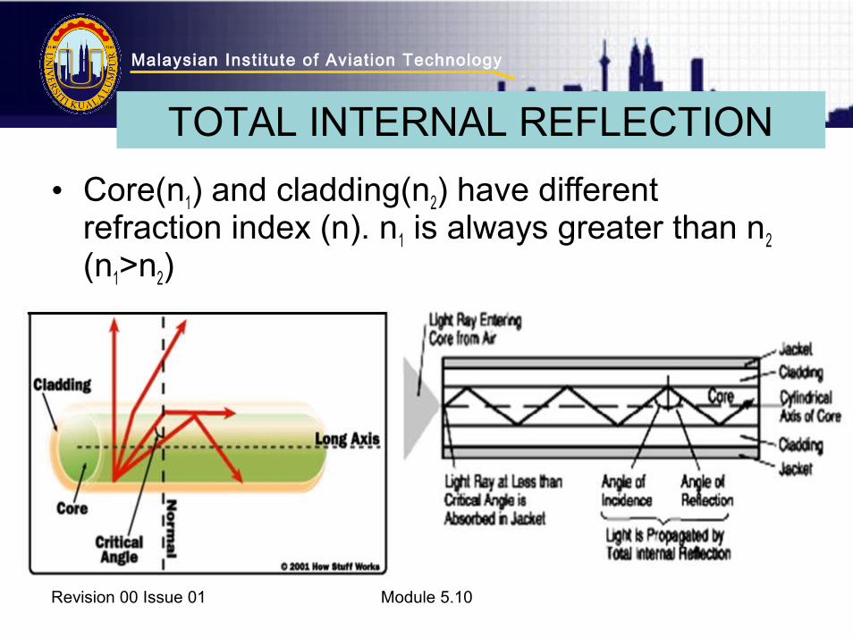
• Core(n1) and cladding(n2) have different refraction index (n). n1 is always greater than n2 (n1>n2)
Revision 00 Issue 01 Module 5.10
TOTAL INTERNAL REFLECTION
Malaysian Inst itute of Aviat ion Technology
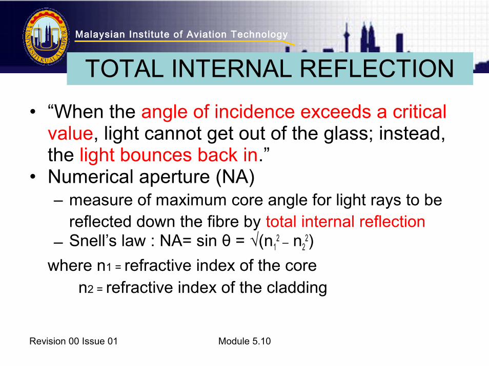
• “When the angle of incidence exceeds a critical value, light cannot get out of the glass; instead, the light bounces back in.”
• Numerical aperture (NA)– measure of maximum core angle for light rays to be
reflected down the fibre by total internal reflection– Snell’s law : NA= sin θ = √(n1
2 – n22)
where n1 = refractive index of the core n2 = refractive index of the cladding
Revision 00 Issue 01 Module 5.10
TOTAL INTERNAL REFLECTION

Malaysian Inst itute of Aviat ion Technology
Revision 00 Issue 01 Module 5.10
Total internal reflection of light in a multi-mode optical fiber.
TOTAL INTERNAL REFLECTION
Malaysian Inst itute of Aviat ion Technology
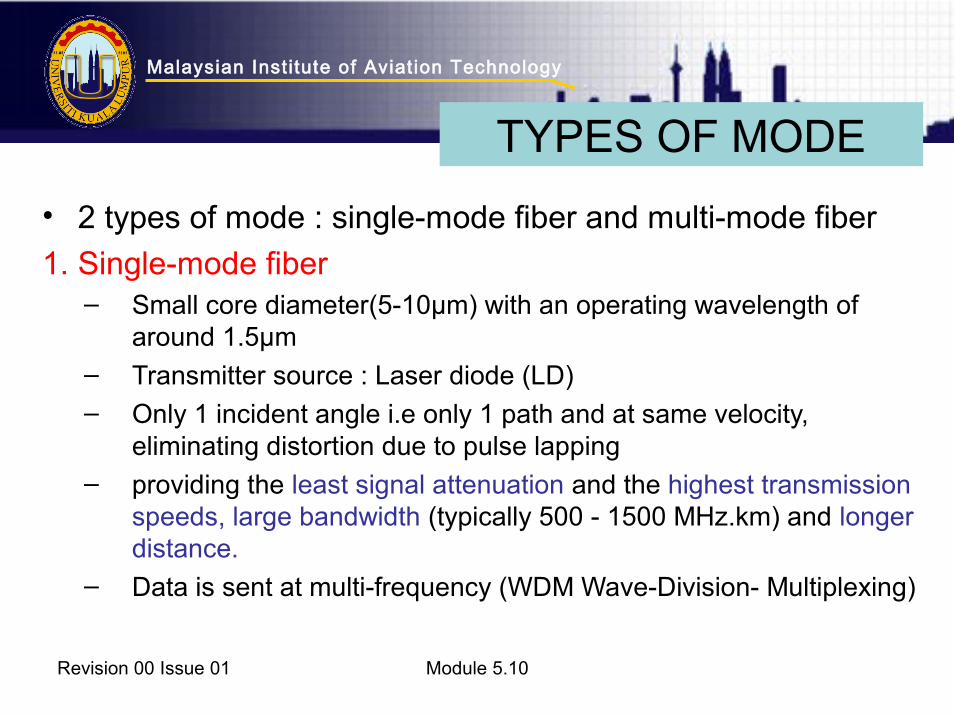
• 2 types of mode : single-mode fiber and multi-mode fiber
1. Single-mode fiber– Small core diameter(5-10µm) with an operating wavelength of
around 1.5µm – Transmitter source : Laser diode (LD)– Only 1 incident angle i.e only 1 path and at same velocity,
eliminating distortion due to pulse lapping – providing the least signal attenuation and the highest transmission
speeds, large bandwidth (typically 500 - 1500 MHz.km) and longer distance.
– Data is sent at multi-frequency (WDM Wave-Division- Multiplexing)
Revision 00 Issue 01 Module 5.10
TYPES OF MODE
Malaysian Inst itute of Aviat ion Technology
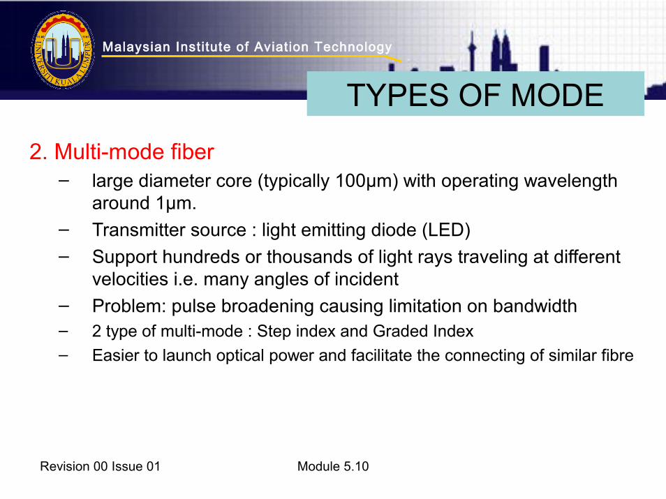
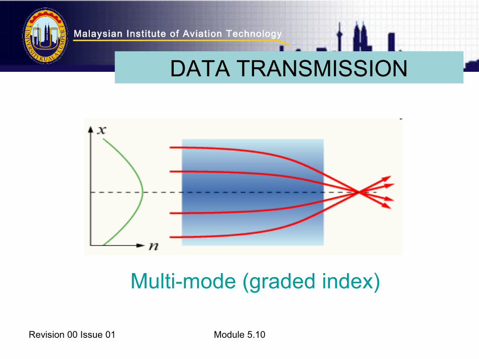
2. Multi-mode fiber– large diameter core (typically 100µm) with operating wavelength
around 1µm. – Transmitter source : light emitting diode (LED)– Support hundreds or thousands of light rays traveling at different
velocities i.e. many angles of incident – Problem: pulse broadening causing limitation on bandwidth – 2 type of multi-mode : Step index and Graded Index
– Easier to launch optical power and facilitate the connecting of similar fibre
Revision 00 Issue 01 Module 5.10
TYPES OF MODE
Malaysian Inst itute of Aviat ion Technology
Revision 00 Issue 01 Module 5.10
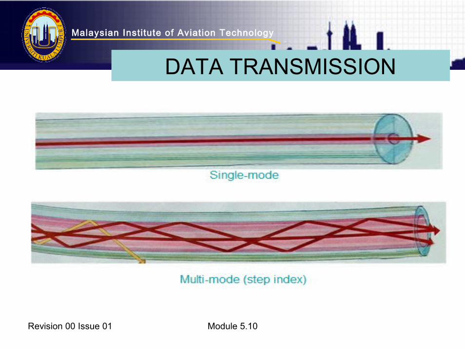
DATA TRANSMISSION
Malaysian Inst itute of Aviat ion Technology
Revision 00 Issue 01 Module 5.10
Multi-mode (graded index)
DATA TRANSMISSION

Malaysian Inst itute of Aviat ion Technology
• Attenuation : signal loss within a fibre and measure in decibels per kilometer (dB/km)
• Star coupler : passive optical coupler which allows the light signals from each fibre stub to be coupled with other fibre stub and then into subsystems
• Wavelength Division Multiplexing (WDM) : signal of different wavelengths are sent down the fibre all together
• Passive optical sensor : optical sensor which do not require electrical supplies or any electronic processing. Used to monitor leading and trailing edge flap, spoilers, ailerons, rudder etc
Revision 00 Issue 01 Module 5.10
TERMINOLOGY
Malaysian Inst itute of Aviat ion Technology
Revision 00 Issue 01 Module 5.10
FIBER OPTIC COMMUNICATION SYSTEM
Malaysian Inst itute of Aviat ion Technology
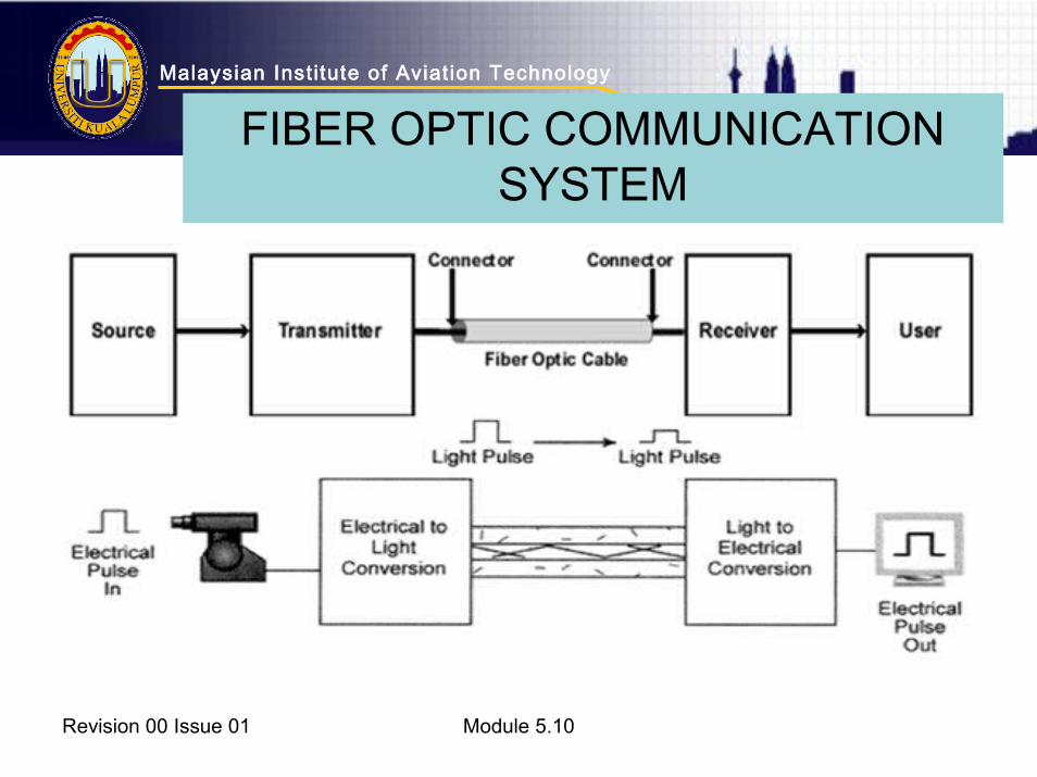
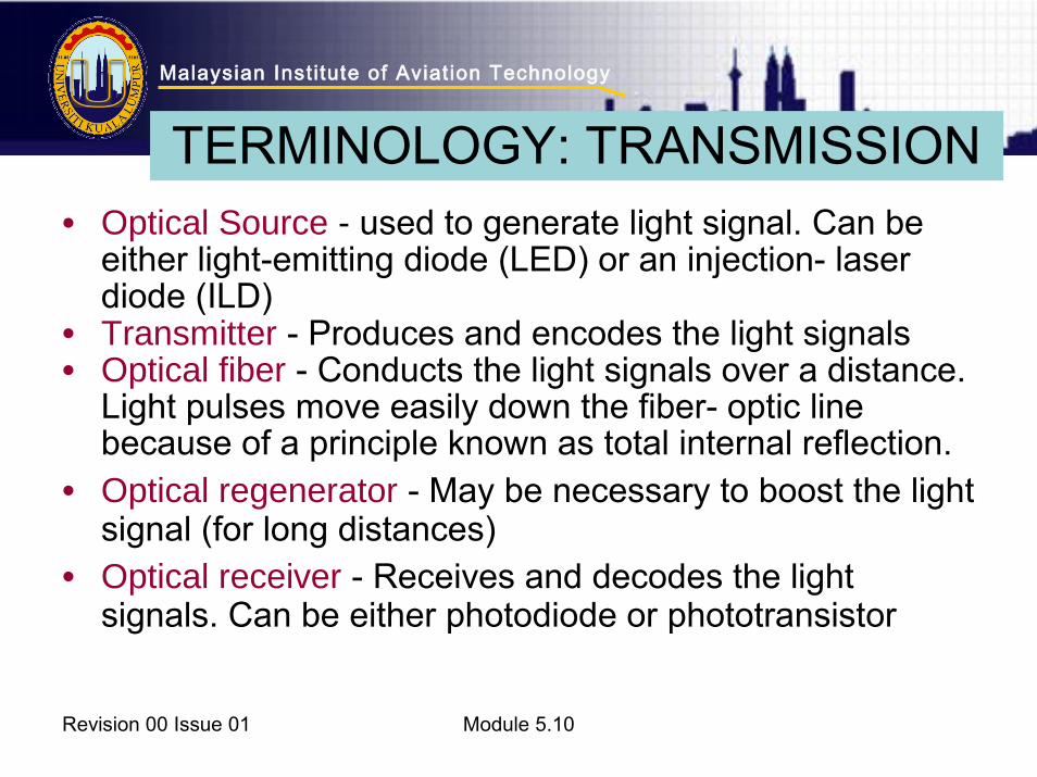
• Optical Source - used to generate light signal. Can be either light-emitting diode (LED) or an injection- laser diode (ILD)
• Transmitter - Produces and encodes the light signals • Optical fiber - Conducts the light signals over a distance.
Light pulses move easily down the fiber- optic line because of a principle known as total internal reflection.
• Optical regenerator - May be necessary to boost the light signal (for long distances)
• Optical receiver - Receives and decodes the light signals. Can be either photodiode or phototransistor
Revision 00 Issue 01 Module 5.10
TERMINOLOGY: TRANSMISSION
Malaysian Inst itute of Aviat ion Technology
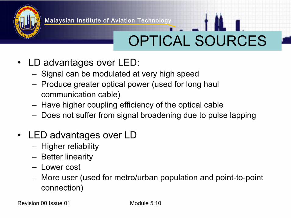
• LD advantages over LED:– Signal can be modulated at very high speed– Produce greater optical power (used for long haul
communication cable)– Have higher coupling efficiency of the optical cable– Does not suffer from signal broadening due to pulse lapping
• LED advantages over LD– Higher reliability– Better linearity– Lower cost– More user (used for metro/urban population and point-to-point
connection)
Revision 00 Issue 01 Module 5.10
OPTICAL SOURCES

Malaysian Inst itute of Aviat ion Technology
Revision 00 Issue 01 Module 5.10
Malaysian Inst itute of Aviat ion Technology
• SPEED: Fiber optic networks operate at high speeds i.e. up into the gigabits
• BANDWIDTH: large carrying capacity • DISTANCE: Signals can be transmitted further without
needing to be "refreshed" or strengthened. • RESISTANCE: Greater resistance to electromagnetic,
electrical isolation, low cross talk (interference) • MAINTENANCE: Fiber optic cables costs much less to
maintain. • PHYSICAL: Smaller size and weight than coaxial or
copper cable buses • USER : able to accommodate more userRevision 00 Issue 01 Module 5.10
ADVANTAGES OF FIBER OPTIC
Malaysian Inst itute of Aviat ion Technology
Revision 00 Issue 01 Module 5.10
FIBER OPTIC VS COPPER
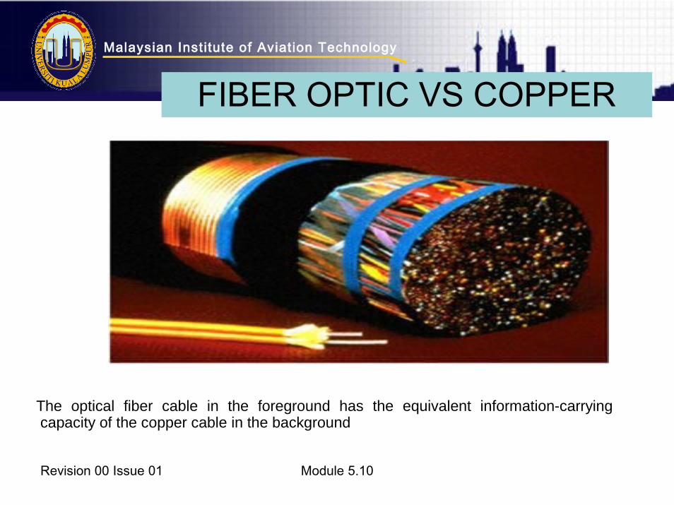
The optical fiber cable in the foreground has the equivalent information-carrying capacity of the copper cable in the background

Malaysian Inst itute of Aviat ion Technology
• Connectors have to be of high integrity • No DC power transmission • Minimum bend radii required • Care when handling - no excessive
pulling, pinching or crimping
Revision 00 Issue 01 Module 5.10
DISADVANTAGES OF FIBER OPTIC

Malaysian Inst itute of Aviat ion Technology
1. Repairing the cable by inserting an in-line splice
- 2 type of splicing : fusion and mechanical - Cleaving : The controlled breaking of a
fiber so that its end surface is smooth. 2. Termination3. Testing
Revision 00 Issue 01 Module 5.10
MAINTENANCE
Malaysian Inst itute of Aviat ion Technology
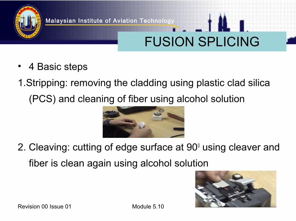
• 4 Basic steps
1.Stripping: removing the cladding using plastic clad silica
(PCS) and cleaning of fiber using alcohol solution
2. Cleaving: cutting of edge surface at 900 using cleaver and
fiber is clean again using alcohol solution
Revision 00 Issue 01 Module 5.10
FUSION SPLICING
Malaysian Inst itute of Aviat ion Technology
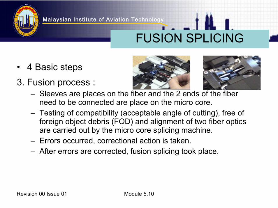
• 4 Basic steps
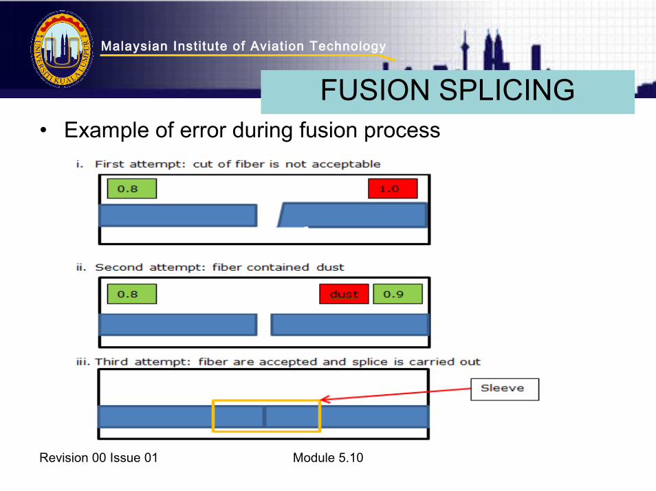
3. Fusion process : – Sleeves are places on the fiber and the 2 ends of the fiber
need to be connected are place on the micro core.– Testing of compatibility (acceptable angle of cutting), free of
foreign object debris (FOD) and alignment of two fiber optics are carried out by the micro core splicing machine.
– Errors occurred, correctional action is taken.– After errors are corrected, fusion splicing took place.
Revision 00 Issue 01 Module 5.10
FUSION SPLICING
Malaysian Inst itute of Aviat ion Technology
• Example of error during fusion process
Revision 00 Issue 01 Module 5.10
FUSION SPLICING

Malaysian Inst itute of Aviat ion Technology
• 4 Basic steps
4. Protection : – A sleeve for the fiber is used to protect the splicing area and
act as a strengthening mechanism for the fiber.– Final testing is simulated using Optical Time Domain
Reflectometer (OTDR).
Revision 00 Issue 01 Module 5.10
FUSION SPLICING
Malaysian Inst itute of Aviat ion Technology
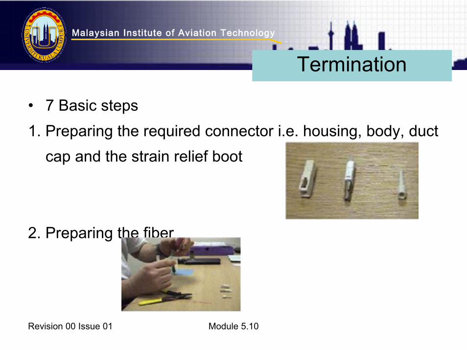
• 7 Basic steps
1. Preparing the required connector i.e. housing, body, duct
cap and the strain relief boot
2. Preparing the fiber
Revision 00 Issue 01 Module 5.10
Termination
Malaysian Inst itute of Aviat ion Technology
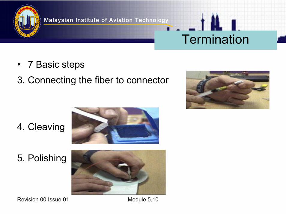
• 7 Basic steps
3. Connecting the fiber to connector
4. Cleaving
5. Polishing
Revision 00 Issue 01 Module 5.10
Termination
Malaysian Inst itute of Aviat ion Technology
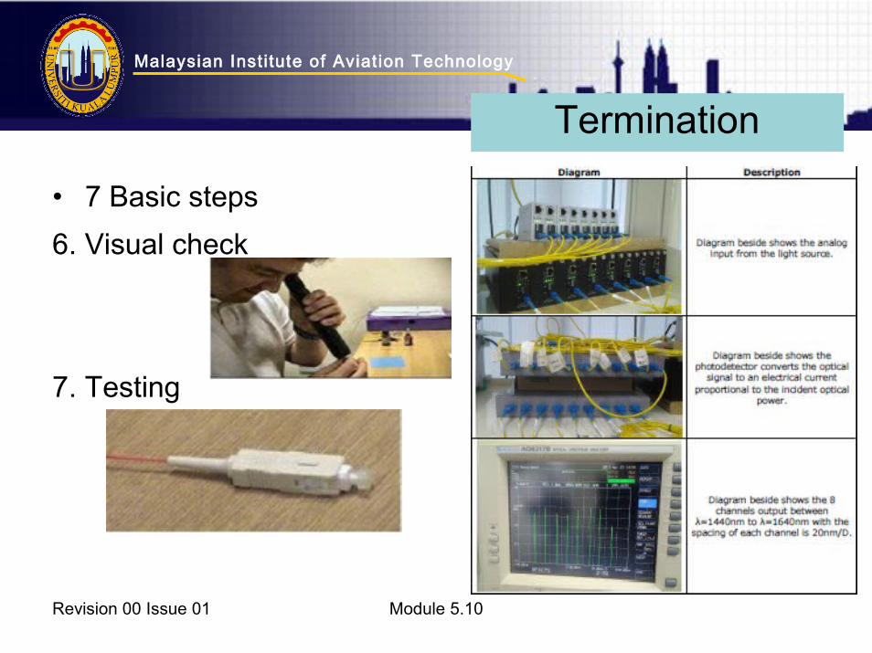
• 7 Basic steps
6. Visual check
7. Testing
Revision 00 Issue 01 Module 5.10
Termination

Malaysian Inst itute of Aviat ion Technology
• Type A- used at production breaks i.e. not regularly
connect-disconnect- Multi channel, in-line (butt type)- Low loss
• Type B– Used to connect to the LRUs; frequently
connect-disconnect
– Multi channel, expended beam (ball lens)Revision 00 Issue 01 Module 5.10
CONNECTORS
Malaysian Inst itute of Aviat ion Technology
• Bus Network- A network topology in which all of the terminals are attached to a
transmission medium serving as a bus
– Commonly called data bus
– The term is used to describe the physical linkage between stations
on a network sharing a common communications
– The bus can only transmit data in one direction, and if any network
segment is severed, all network transmission ceases.
Revision 00 Issue 01 Module 5.10
TERMINOLOGY OF NETWORK
Malaysian Inst itute of Aviat ion Technology
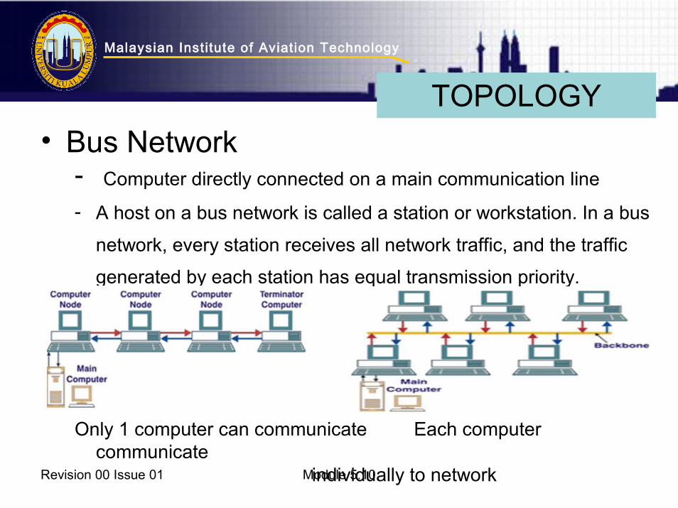
• Bus Network- Computer directly connected on a main communication line
- A host on a bus network is called a station or workstation. In a bus
network, every station receives all network traffic, and the traffic
generated by each station has equal transmission priority.
Only 1 computer can communicate Each computer communicate
individually to networkRevision 00 Issue 01 Module 5.10
TOPOLOGY

Malaysian Inst itute of Aviat ion Technology
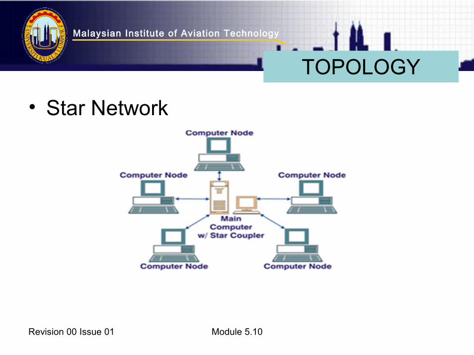
• Star Network- one of the most common computer network
topologies. - In its simplest form, a star network consists of one
central switch, hub or computer, which act as a
conduit to transmit messages. - This consists of a central node, to which all other
nodes are connected; this central node provides a
common connection point for all nodes through a hub
Revision 00 Issue 01 Module 5.10
TERMINOLOGY OF NETWORK
Malaysian Inst itute of Aviat ion Technology
• Star Network
Revision 00 Issue 01 Module 5.10
TOPOLOGY
Malaysian Inst itute of Aviat ion Technology
• Advantages- Better performance
- Isolation of devices
- Centralization: increasing in capacity, or connecting additional
devices to it, increases the size of the network very easily and allows
the inspection of traffic through the network
- Easy to detect faults and to remove parts.
- No disruptions to the network when connecting or removing devices.
- Installation and configuration is easy
Revision 00 Issue 01 Module 5.10
STAR NETWORK
Malaysian Inst itute of Aviat ion Technology
• Disadvantages
- High dependence of the system on the functioning of the central hub.
Failure of the central hub renders the network inoperable
- There is central server dependency.
- Expensive to purchase.
- Requires a large amount of cable to be connected.
Revision 00 Issue 01 Module 5.10
STAR NETWORK

Malaysian Inst itute of Aviat ion Technology
• Ring Network- a network topology in which each node connects to exactly two
other nodes, forming a single continuous pathway for signals
through each node - a ring. Data travel from node to node, with
each node along the way handling every packet.
Revision 00 Issue 01 Module 5.10
TOPOLOGY
Malaysian Inst itute of Aviat ion Technology
• Advantages- Very orderly network where every device has access to the token
and the opportunity to transmit
- Performs better than a bus topology under heavy network load
- Does not require a central node to manage the connectivity
between the computers
- Quite easy to install and reconfigure since adding or removing a
device requires moving just two connections.
- Point to point line configuration makes it easy to identify and isolate
faults.
Revision 00 Issue 01 Module 5.10
RING NETWORK

Malaysian Inst itute of Aviat ion Technology
• Disadvantages- One malfunctioning workstation can create problems for the entire
network. This can be solved by using a dual ring or a switch that
closes off the break.
- Moving, adding and changing the devices can affect the network
- Communication delay is directly proportional to number of nodes in
the network
- Bandwidth is shared on all links between devices
- More difficult to configure than a Star: node adjunction = Ring
shutdown and reconfigurationRevision 00 Issue 01 Module 5.10
RING NETWORK
Malaysian Inst itute of Aviat ion Technology
• In Boeing 7771.Avionics local area network (LAN)
- Aircraft Information Management System (AIMS)
- Maintenance Access Terminal (MAT)2. Cabin LAN
– Zone network controller
– Cabin file server (CFS)
Revision 00 Issue 01 Module 5.10
APPLICATION


