Image Topic: o Nam elementum commodo mattis. Pellentesque malesuada blandit euismod. Topic: o Nam elementum commodo mattis. Pellentesque malesuada blandit euismod. o Nam elementum commodo mattis. Pellentesque malesuada blandit euismod. Topic: o Nam elementum commodo mattis. Pellentesque malesuada blandit euismod. TITLE Design of Flyover QSFP (FQSFP) for 56+ Gbps applications Presented by Jim Nadolny, Samtec Authors Kyoungchoul Koo(1), Pranay Vuppunutala(1), Jim Nadolny(3), Atieh Talebzadeh(1), Yuan Chen(1), Qian Wang(2), Ben Cooper(3), David Pommerenke(1), James L. Drewniak(1) (1) Missouri University of Science and Technology (2) Xilinx (3) Samtec
Transcript
Image
Topic:
o Nam elementum commodo mattis. Pellentesque
malesuada blandit euismod.
Topic:
o Nam elementum commodo mattis. Pellentesque
malesuada blandit euismod.
o Nam elementum commodo mattis. Pellentesque
malesuada blandit euismod.
Topic:
o Nam elementum commodo mattis. Pellentesque
malesuada blandit euismod.
TITLE
Design of Flyover QSFP (FQSFP) for 56+ Gbps applicationsPresented by Jim Nadolny, Samtec
Authors
Kyoungchoul Koo(1), Pranay Vuppunutala(1), Jim Nadolny(3), Atieh Talebzadeh(1), Yuan Chen(1), Qian Wang(2), Ben Cooper(3), David Pommerenke(1), James L. Drewniak(1)
(1) Missouri University of Science and Technology(2) Xilinx(3) Samtec
The motivation is to take advantage of the reduced attenuation that twinax cable provides
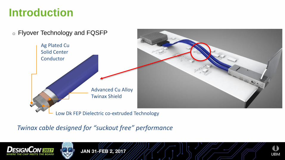
o Flyover Technology and FQSFP
Introduction
A short, high performance connector near the switch chip…
o Flyover Technology and FQSFP
Introduction
A QSFP connector with direct attach twinax…
o Flyover Technology and FQSFP
Introduction
Twinax cable designed for “suckout free” performance
Ag Plated Cu Solid Center Conductor
Advanced Cu Alloy Twinax Shield
Low Dk FEP Dielectric co-extruded Technology
o IEEE 802.3bs interconnect requirements
o Front panel pluggable solutions (QSFP) are qualified using compliance boards
o Host compliance board tests the module
o Module compliance board test the host
o Compliance boards for 100 GbE are defined in IEEE 802.3bj (4 channels at 28 Gbps NRZ)
o Compliance boards for 400 GbE are the same as IEEE 802.3bj (8 channels at 56 Gbps PAM4)
o This may evolve as PAM4 implementations mature
Introduction
To show 56 Gbps PAM4 compliance, we take a mated host-module compliance board approach
Introduction
To show 56 Gbps PAM4 compliance, we take a mated host-module compliance board approach
PCB
Host compliance boardHost compliance board
Module compliance board
o IEEE 802.3bs interconnect requirements
Reference plane location
Introduction
To show 56 Gbps PAM4 compliance, we take a mated host-module compliance board approach
Mated compliance board limits
FQSFP simulated data
EMI Characterization of FQSFP
Approach:
• Full wave simulations of small, simple structures• Quick(er) computational time• Validate with measurements • Build confidence that future steps are built on solid ground
• Start with the QSFP connector
• Incrementally build the model and validation vehicles
Avoid the rookie mistake of putting the entire cable assembly, EMI cage, chassis model and PCBs into CST/HFSS and simulating the total radiated power (TRP)
EMI Characterization of FQSFPDesign of test vehicle
EMI Characterization of FQSFPComputational Approach
EMI Characterization of FQSFPTweaking the model to reflect the test vehicle
EMI Characterization of FQSFPS-Parameter Measurements
EMI Characterization of FQSFPTime Domain Correlation
EMI Characterization of FQSFPFull Wave Simulation
• Energize the twinax cable
• Energy excites the connector, PCB, etc.
• Total radiated power computed by
integrating over the computational
domain
EMI Characterization of FQSFPTRP Measurements
• As with S-parameter measurements,
calibration is required to compensate for
reflections and attenuation.
• Methodology is NIST traceable
EMI Characterization of FQSFPTRP Measurements
We measured the radiation from just the connector
EMI Characterization of FQSFPTRP Measurements
We measured the radiation from just the connector
EMI Characterization of FQSFPTRP Measurements
• Differential results show poor
correlation
EMI Characterization of FQSFPCorrelation efforts
Differential correlation improvement when instrumentation skew is compensated
Next Steps
• More fully explore the twinax to EMI cage termination