+ All Categories
Home > Documents > TOPICAL REPORT ADDENDUM GoPY

TOPICAL REPORT ADDENDUM GoPY

Date post: 16-Feb-2022
Category:
Upload: others
View: 1 times
Download: 0 times
Share this document with a friend
33
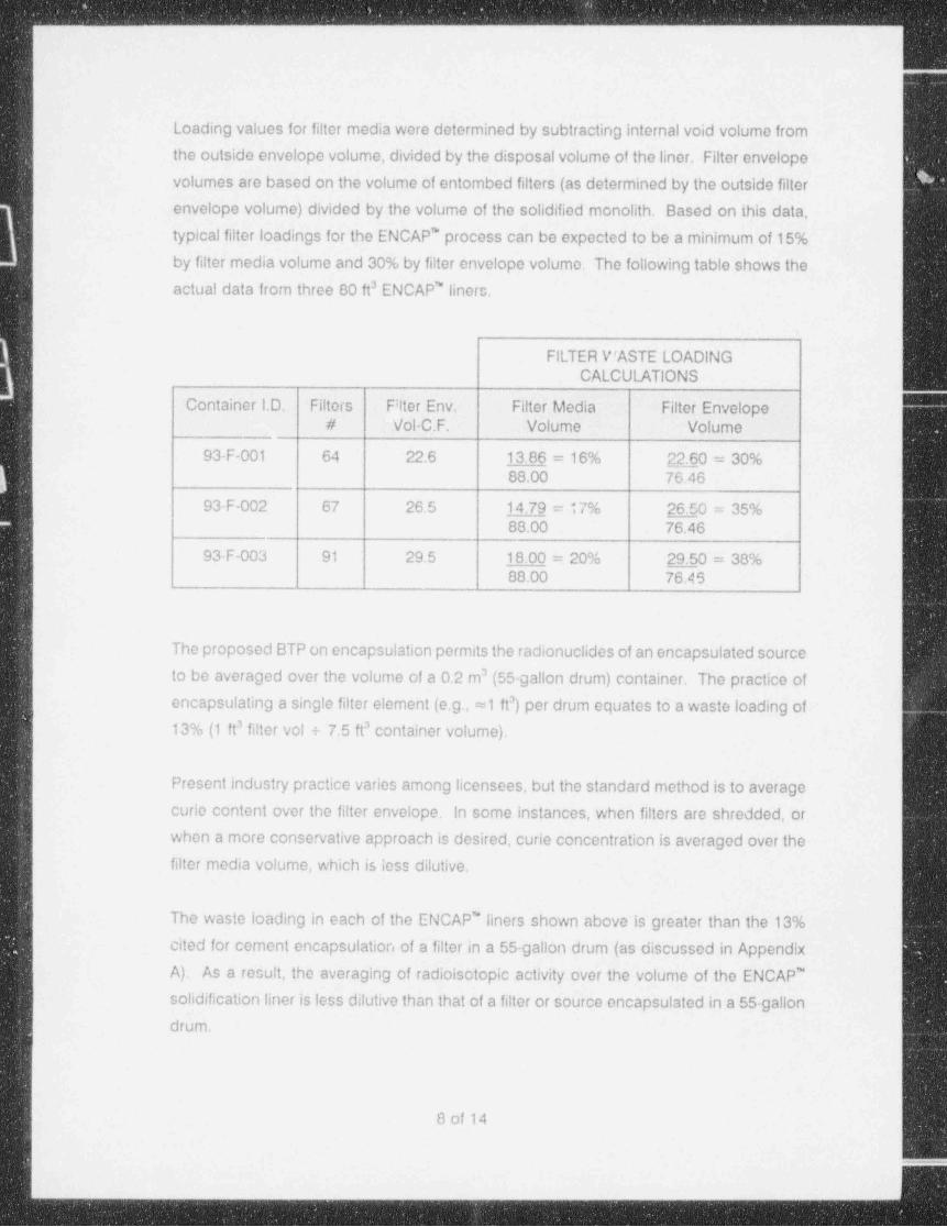
_ . TOPICAL REPORT ADDENDUM GoPY ENCAP' Encapsulation Utilizing The VERl" Solidification Process (Docket Number WM-105R1) T.R. No. DT-VERI-100-NP/P-A Revision 1 Addendumi I i Volume 1 - Non-Proprietary i May 1,1994 | | ; I I i I Submitted by Diversified Technologies Services, Inc. ; 2680 Westcott Blvd. i Knoxville, TN 37931 Phn: 615-539-9000 Fax: 615-539-9001 i 9405120075 940501 PDR WASTE WM-105 PDR --r y- g-
Transcript

_

.

TOPICAL REPORT ADDENDUM

GoPYENCAP' Encapsulation UtilizingThe VERl" Solidification Process

(Docket Number WM-105R1)

T.R. No. DT-VERI-100-NP/P-ARevision 1

Addendumi

Ii

Volume 1 - Non-Proprietary

iMay 1,1994 |

|;

I

Ii

I,

Submitted by

Diversified Technologies Services, Inc.;

2680 Westcott Blvd. i

Knoxville, TN 37931Phn: 615-539-9000Fax: 615-539-9001

i

9405120075 940501PDR WASTEWM-105 PDR

--r y- g-

- . - . . - ,-. .. .-. . - . . . . - _ - . . - . - . - - - .- .- . .

i1

TABLE OF CONTENTS I

i. .

Sec. TITLE Page

TABLE OF CONTENTS . i~

.. .. ... .. . ., . .

ABSTRACT ii'

.... .. . .... . . .. . . ..

,

1.0 INTRODUCTION 1.. .. . . .. . ... .. .

4

2.0 PROCESS DESCRIPTION. 1.. . ... ... . ... .

3.0 ENCAPSULATION LINER 2. ..... . . .. ....

| 4.0 WASTE FORM 4. . . ... ..... ....

|

5.0 WASTE LOADINGS . 7. .. . .. . ... . .

6.0 VOIDS AND HOLIDAYS 8. . . .. . ...

7.0 PROSCRIBED WASTES 9. . .... . . .

8.0 ACCEPTANCE FOR BURIAL 11, .. .. . . .

.

9.0 FULL-SCALE EXPERIENCE 12.. ... . . .... .

10.0 SUMMARY 13. . . . . . . . . . . ..

GRAPHICS:

Fig.1-NP, ENCAP' Liner: Protective Cage .

Fig. 2-NP, ENCAP* Protective Cage

Fig. 3-NP, Compressive Strength Test: Start

Fig. 4-NP, Compressive Strength Test: Endi

Fig. 5-NP, Monolith: VES Fusion to FRP

Fig. 6-NP, Sample: VES Fusion to FRP

APPENDIX: |

A. Rationale for Curie Concentration Averaging

B. Analysis of StructuralIntegrity

i

. ___ _ __________ __ _ _ _ . . .. _. .

__ _ _ _ __ ~. _ _ . -_ _ _ _ . _ . . _ _ . .. _ _ _

ABSTRACT

This Addendum to Topical Report DT-VERI-100-NP/P-A, VERI' (Vinv! Ester Rosin in Situ)

Solidification Process for Low-Level Radioactive Waste (Docket Number WM-105R1) presents,

information and data in support of a process of heterogenous waste encapsulation in a polymer

matrix. This process, hereafter referred to as ENCAP', utilizes the NRC-approved waste forms

generated using the VERl" process referenced in the parent Topical Report (TR) to encapsulate

or entomb waste in the solidified free-standing monolith. The incorporation of non-uniform wast'e

products in the monolith generates a heterogenous waste form. The encapsulated waste is

intended to be composed primarily of spent filter cartridges or similar solids.

This TR revision describes the process for encapsulating heterogenous wastes ir, an entombing

monolithic polymer matrix, including steps taken to protect the integrity of the monolith, the

design basis to preclude environmental exposure of the entombed waste, and limitations on the

applicability of the process.

Results of full-scale filter cartridge encapsulation efforts undertaken in 1993 are discussed and

cited as qualitative evidence of efficacy of the encapsulation process.

I|

l

ii

)l

|

|

|

|

ii

_ _ _ _ _ _ _ _ _ _ _ _ _ _ _ _ _ _ _ _ _ _

. .. . , _ _ . - . _. -. .--

i

1,0 INTRODUCTION,

The ENCAP' Process is needed by the nuclear industry to minimize the environmental !

impacts and costs of shallow land burial (at low level waste disposal facilities) of waste

filter cartridges from nuclear power plants. The reduction in environmental impact and in

waste disposal costs would be achieved through reduced handling of waste packages

at the reactor site, during transport, and at the disposal faciidy. The use of this process

would also reduce burial space requirements for waste filter cartridges because the'

relative space the large waste liners it employs would than for the smaller waste packages

currently in use. 1

,

The traditional methods of waste filter cartridge disposal have been 1) to encapsulate a

single filter cartridge in grout inside a 55-gallon drum (alse referred to as a liner) or 2) to

place several filters inside a high integrity container (HIC).

The ENCAP' Process would result in encapsulation of numerous filter cartridges in a :

matrix of vinyl ester styrene and spent ion exchange bead resins. The spent bead resins

may or may not be contaminated with radionuclides. A 200 ft ENCAP' monolith could

encapsulate from 20 to approximately 100 filter cartridges. The number of cartridges in

a given ENCAP* container would depend on upon the total envelopo volume of all the<

filter cartridges, the total radionuclide content of the cartridges and the radionuclide !

content of the spent ion exchange resin beads in the ENCAP' matrix.

2.0 PROCESS DESCRIPTION

The ENCAP' process uses VERI' solidification to create an enveloping monolith around !

a caged region of heterogenous wastes (i.e., spent filter cartridges). The ENCAP' processJ

involves preparation of an encapsulation liner and internal cage (as described in this

document) and solidification of the resulting resin-filled liner with the VERl' polymersolidification process described in the parent TR.

An encapsu!:: tion liner is set up with dewatering internals in the same manner as that

described in the parent TR for preparation of a solidification liner. A cage which complies

with the design criteria discussed in this document is placed in the liner in preparation forreceiving waste.

1 of 14

.- _ _ - ---

__. ___ _ __ _ _. ._._ _ - _ _ ._ . _

.

:

A protective layer of ion exchange resin is introduced to the liner; This resin layer must

be a minimum of 4" deep, and may consist of either contaminated or non-contaminated

resins. The resin may be sluiced with water or manually poured into the liner. Permitted

resins are described in the parent TR.

This resin layer serves a dual function of physically protecting the dowatering internals I

from damage during introduction of filter cartridges and establishing the bottom I

exclusionary zone which consists entirely of VERI'-solidified resins..

When the cage has been filled with filter cartridges or other wastes to be entembed, the

cage lid is closed and the liner is filled with ion exchange resin to a level covering thecaged waste a minimum of 4". The fill resin may be contaminated or non-contaminated,

as long as it is of the type identified in the parent TR as being accepted for VERl*solidification.

!

lThe resin may be sluiced in a slurry form or manually poured from containers in a dry or

damp state, Dry resin, like slurried resin, tends to flow wellinto the crevices and channels

of the waste cage. Damp resin, if manually introduced to the liner, tends to clump,;

resulting in uneven distribwion. The liner may be filled with water to permit the damp

resin to become buoyant in the aqueous solution, and to migrate readily throughout the- )encapsulation liner.

When the ENCAP' liner has been filled with resin, VERI' solidification equipment is

positioned as described in the parent TR, and the VERI' process proceeds in the same

manner. Upon completion of introduction of the catalyzed and promoted binder to the

encapsulation liner, the exotherm is monitored, compliance with acceptance critoria is

verified, and the ENCAP' liner is capped and prepared for shipment.

3.0 ENCAPSULATION LINER

The encapsulation liner is a right cylinder of carbon stoel or polyethylene plastic with

maximum bounding dimensions of 78"in diameter and 72"in height, yielding a maximum !

volurae of approximately 200 cubic feet. The configuration, dewatering internals and

maximum !iner size are described in TR DT-VERI-100-NP/P-A. No credit is taken for the

structural strength of the disposal liner in the encapsulation process for waste form |

qualification.

2 of 14

.. -. .. - - - ,-

_ . _ _ _ _ _ _ _ _ _ _ _ _ - _ _ _ . . _ _ _ _ _ . _ _ _ _ _ _ _ _ _ _ _ _ _ _ _ _ _ _ - _ _ _ _ _ _ _ _ _ _ _ _

e

The structural integrity of the ENCAP' carbon steel or poly (HIC) liner does apply for

compliance with DOT regulations as well as integrity requirements for handling themonolith at the burial site.

The key feature of the encapsulating liner is a cage positioned inside the liner for receipt

of the material to be encapsulated. This cage is designed to create an exclusionary zone

between the entombed waste and the side wall of the encapsulation liner. Several generic

features must be incorporated in the cage to ensure maintenance of the exclusionaryzone, including the following design characteristics:

maintenance of a minimum 4" free space between the cage and the bottom anda

outside wall of the liner; '

construction of perforated carbon steel, heavy wire mesh, fiberglass sheet or othera

material of sufficient strength to maintain its physical shape and the minimum boundary

region when filled with filter elements;

I

a minimum of 10% of the cage's surface area must consist of holes or slots whicha

result in arcas of contiguom., solidified media connecting the entombed waste to the

boundary exclusionary region;

a closure device to prevent buoyant filters or other objects from surfacing whena

submerged in the polymer matrix prior to gelation;

a stand-offs or other material used for physically positioning or supporting the cage shall

be of material and a desion (emphasis added) which precludes corrosion (which is

prohibited and which may result in a pathway between the entombed waste and the

environment) during storage / burial;

a when possible, stand-offs and other supports shodd be fabricated of material which

will fuse to the curing polymer (e.g., fiberglass raaterial cured with either polyester or. vinyl ester resin).

A general configuration drawing of the ENCAP' liner is shown in Fig.1 of the Graphics

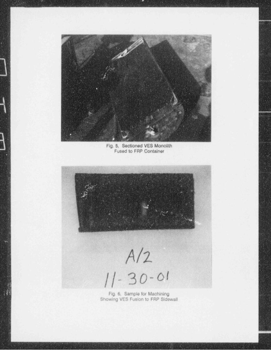
attachment to this report. Details typica of the ENCAP' protective cage appear in Fig. 2.

Fig. 5 and 6 are photographs of a VERI' solidified mass fused to the FRP side wall of a

3 of 14

- - -_-- _____-

_ _ . _ _ _ _ _ - _ _ - _ _ _ _ _ _ _

container. The chemical fusion between the VERl" mass and the FRP material resistsdelamination even when cha!!enged with mechanical separation (e.g. penetration with a

screwdriver).'

4.0 WASTE FORM

The encapsulating waste form is spent ion exchange resin solidified in a VES polymer

matrix, as described in TR DT-VERI-100-NP/P-A. The waste to be encapsulated does not

affect the structural integrity of solidified monolith when the potential void spaces are

limited as shown in the structural analysis and discussion presented in Appendix B. Such

waste form characteristics as compressive strength, water immersions, biodegradation,

irradiation tolerance and leachability are not influenced by the entombed waste.

Minimum Reauirements [10 CFR 61.56(all

Packaging [10 CFR 61.56(a)(1)]

The waste form will be contained in steel drums or liners, thus satisfying the requirement

that waste must not be packaged in cardboard or fiberboard boxes.

Liquid Waste [10 CFR 61.56(a)(2)]

This section specifies that liquid waste must be solidified or packaged in sufficient

absorbent material to absorb twice the volume of the liquid. The liquid portion of the

waste will be solidified in the VES binder, and thus fulfill this requirement.,

,

Free Liquid [10 CFR 61.56(a)(3)]

This section specifies that free-standing liquid in the solid waste shall not exceed 1% of

the volume of the solid waste. The objects encapsulated by this process may contain

small amounts of liquid which are not displaced by the binder. Examples of such liquids

are water held in inside-loading filter cartridges or in the irregular shapes of otherwise-solid objects.

1

All excess liquid is removed during the dewatering process described in the parent TR.

Any remaining liquid associated with the objects to be entombed will be entombed / 1

4 of 14

_ _ _ -

. - _ - _ _ - _ _ _ _ _ _ - _ _ _ _ _ _ _ _ _ _ _ _ _ _ _ _ _ - _ _ _ _ _ _ _ _ _ _ _ _ _ _ _ _ _ - _ _ _ _ _ _ _ _ - _ _ _ _ _ _ _ . _ _ _ _ _ _ _ - _ _ _ _ _ _ _ _ _ _ _ _ _ _ _ _ _ -

,

..

encapsulated with the object. Due to the general impervious and water immersion

characteristics of the VERI'-solidified resin (as damonstrated in the wasto form testing for

the parent TR), such liquids will be offectively isolated within the monolith and are not free

to migrate to the environment, even when the liner corrodes away in the burial.

environment. Therefore, any water present in the entombed waste does not constitute

free standing water or free liquid as defined by 10 CFR 61.56(a)(3).

Empirical testing performed in support of the parent TR demonstrates that a liner

containing spent ion exchange resin (or other process media as defined in the TR) and

solidified with the VERI' process results in a final waste form which complies with the

maximum permissible volume of free standing water of <1% by volume of waste.|

Reactivity of Product [10 CFR 61.56(a)(4)]

This section specifies that the waste must not be readily capable of detonation, explosive

decomposition, reaction at normal pressures and temperatures, or explosive reaction with

water. The solidified binder and contained waste meet all those requirements.

Toxic Gas Generation [10 CFR 61.56(a)(5)]

|

This section specifies that the waste must not be capable of generating toxic gases,

vapors, or fumes harmful to persons transporting, handling. or disposing of the wasto

form. The solidified VES emits none of the above that would be harmful to personnel.

Pyrophoricity (10 CFR 61.56(a)(6)]|

This section specifies that a waste must not be pyrophoric, as defined in 10 CFR 61.2 of

the regulations. The solidified waste forms are not pyrophoric, nor do they contain any

materials which are pyrophoric. Therefore, the encapsulated / solidified wastes satisfy this

requirement.

Gaseous Wastes [10 CFR 61.56(a)(7)]

This encapsulation / solidification process is not proposed for use on gaseous wastos, so

this section of the regulation is not applicab:e to the Diversified Technologies waste forms.

5 of 14

..

_ _ . _ _ _ _ _ . . - _ . _ _ - _ . _ _ . - - - -

_ _ _ _ _ _ _ __ _ _ __ _ _ _ _ _ __ _ ----- _ -_- _ _ _ _ _ _ _

Hazardous Waste [10 CFR 61.56(a)(8)]

This section requires that waste containing hazardous, biological, pathogenic, or

infectious material be treated to reduce to the maximum extent practicable the potentialhazard from the ncn-radiological materials. .

Neither the VERl*-polymerized binder material nor the waste stream materials identified

will contain. materials defined as hazardous, biological, pathogenic, or infectious.<

Numerous TCLP_ tests of the binder, catalyst, promoter, and additives have consistently

shown the polymerized form to be non-hazardous both with and without the presence ofwastes.

Stability Requirements [10 CFR 61.56(b)

This section requires that the solidification process result in a waste form with structural

stability. Stability is intended to ensure that the waste does not structurally degraie and;

affect the overall stability of the burial site subsidence through slumping, collapse, orother

failure of the disposal unit leading to water infiltration. Stability is also a factor in limiting

exposure to an inadvertent intruder, since it provides a recognizable and non-dispersible

waste form.

Structural Stability

The ENCAP' entombing of waste within the VERl*-solidified monolith does not physically.

impair dimensional stability under the expected dispcsal conditions such as weight of

overburden and compaction equipment. Previous testing has shown that the presence

of liquid, microbial activity, and radiation (when limited to <1 x 10" Rad) has no negative

effect on the structural integrity of the binder matrix and, hence, the integrity of tho'monolith.

It has been shown, as reported in the parent TR, that the compressive strength (typically

>2000 psi) of the VERI' waste form is several factors greater than the minimum required

for stability. Qualitatively, the plasticity of the VERI' waste form is well suited for

encapsulation. This plasticity is evident during compressive strength testing as shown in i

Fig 3 and 4 in the attachments to this report..

4

6 of 14{

_ _ _ - _ _ _ _ - _ _ - _ _ _ - = . - _. -_

|

Hazardous Waste [10 CFR 61.56(a)(8))

This section requires that waste containing hazardous, biological, pathogenic, or

infectious material be treated to reduce to the maximum extent practicable the potential

hazard from the non-radiological materials.,

,

Neither the VERl'-polymerized binder material nor the waste stream materials identified

will contain materials defined as hazardous, biological, pathogenic, or infectious.

Numerous TCLP tests of the binder, catalyst, promoter, r.nd additives have consistently

shown the polymerized form to be non-hazardous both with and without the presence of

wastes.

Stability Requirements [to CFR 61.56(b) '

This section requires that the solidification process result in a waste form with structural

stability. Stability is intended to ensure that the waste does not structurally degrade and,

affect the overall stability of the burial site subsidence through slumping, collapse, or other

failure of the disposal unit leading to water infiltration. Stability is also a factor In limiting

exposure to an inadvertent intruder, since it provides a recognizable and non-dispersible

waste form.,

Structural Stability

The ENCAP' entombing of waste within the VERI'-solidified monolith does not physically

impair dimensional stability under the expected disposal conditions such as weight of

overburden and compaction equipment. Previous testing has shown that the presence

of liquid, microbial activity, and radiation (when limited to <1 x 10" Rad) has no negative,

effect on the structural integrity of the binder matrix and, hence, the integrity of the--monolith.

,

it has been shown, as reported in the parent TR, that the compressive strength (typically

>2000 psi) of the VERI' waste form is several factors greater than the minimum required !

for stability. Qualitatively, the plasticity of the VERI' waste form is -well suited for

encapsulation. This plasticity is evident during compressive strength testing as shown in

Fig 3 and 4 in the attachments to this report.

6 of 14

_ . . . _ . _ __. . _ _ . _ . _ __

. .. .. . . .

. - - _ - _ _ - -

Unlike cementious waste samples (which tend to experience acute failure by sheering or

spalling during testing), the VERI' waste form tends to bulge circumferentially without

failure when subjected to maximum yield compressive forces. It is postulated that this

plasticity may tend to protect the integrity of the monolith when subject to compressive

forces in the burial environment. It should be noted that no credit is taken for the

favorable plasticity of the waste form in establishing tho ability of the waste form to

maintain integrity of the monoliths. The information is presented simply for its anecdotal

value.,

Likewise, no credit for stability is taken for the containers in which the VERI' process is

used. In those instances when the entombed waste may be stored on an interim basis

before final disposal, consideration should be given to performing the ENCAP' process

in corrosion-resistant containers such as poly containers or lined carbon steel liners.

Such corrosion resistance, while not an issue from a waste form perspective, may be

important to ensure viability of the waste package a number of years from now, when the

waste is moved from its storage site to the transport cask for disposal. No aspect of the

ENCAP' process is affected by, or prohibits use in, such containers.

Appendix B of this report presents a discussion and mathematical analysis of the impact

of potential voids spaces created by the entombed waste on the integrity of the monolith.

The waste forms produced by the ENCAP' process meet the structural stability

requirements of land burial or burial in an engineered barrier system. The minimum I

separation of the waste-containing cage from the side wall of the container is intended

to ensuri sufficient strength to prevent environmentalintrusion into the caged waste area,

or escape of waste from the area. The filling of interstitial space within the caged waste

provides additional strength and stability to the monolith.

5.0 WASTE LOADINGS

Waste loadings (or packaging efficiencies), for ENCAP' entombing of spent filter !

cartridges were ascertained from full-scale encapsulations. Filter media loading values

for the 80 ft ENCAP' liners referenced in the table below are based on the volume of j

ontombed filters calculated by two different methods.

7 of 14

!\. ... ., . .

_ _ - _ _ _ _ _ _ - _ _ - _ _ _ _ _ _ _ _ - _ . _ _ _ _ _ _ - - - - - _ _ - _ _ _ _ _ _ _ _ - - _ -

.

.. . ._ _ _ _ - _ _ _ _ _ - _ _ _ _ _ _ _ _ - _ _ _ _ _ ___-____

4

Loading values for filter media were determined by subtracting internal void volume from

the outside envelope volume, divided by the disposal volume of the liner. Filter envelope !

volumes are based on the volume of entombed filters (as determined by the outside filter

envelope volume) divided by the volume of the solidified monolith. Based on this data,

typical filter loadings for the ENCAP' process can be expected to be a minimum of 15%

by filter media volume and 30% by filter envelope volume. The following table shows the

actual data from three 80 ft' ENCAP' liners. -

.

FILTER VfASTE LOADINGCALCULATIONS

. Container I.D. Filters . Filter Env. Filter. Media - Filter Envelope -.# Vol-C.F. ' Volume Volume

93-F-001 64 22.6 13.86 = 16% 2240 = 30%88.00 76.46

93-F-002 67 26.5 14.79 = 17% 26.50 = 35%88.00 76.46

93-F-003 91 29.5 18.00 = 20% 29.50 = 38%88.00 76AS

The proposed BTP on encapsulation permits the radionuclides of an encapsulated source

to be averaged over the volume of a 0.2 m (55-gallon drum) container. The practice of

encapsulating a single filter element (e.g., ==1 ft ) per drum equates to a waste loading of

13% (1 ft filter vol + 7.5 ft container volume).

Present industry practice varies among licensees, but the standard method is to average

curie content over the filter envelope. In some instances, when filters are shredded, or

when a more conservative approach is desired, curie concentration is averaged over thefilter media volume, which is less dilutive.

The waste loading in each of the ENCAP' liners shown above is greater than the 13%

cited for cement encapsulation of a filter in a 55-gallon drum (as discussed in Appendix

A). As a result, the averaging of radioisotopic activity over the volume of the ENCAP'

solidification liner is less dilutive than that of a filter or source encapsulated in a 55-gallon

drum.

8 of 14

:

_ _ _ _ _ _ _ _ _ _ _ _ _ _ . _ - _ - _ _ _ - - - . - _ - - - - - - - - - - - - - - - - - -- - - - - - - - - - - ' - ' - - - ' ' ' - - '

_ _ , _ _ . - _ _ _ _ _ _ _ _ _ _ _ __ _ _ _ _ _ _ _ _

6.0 VOIDS AND HOLIDAYS

<

A number of qualitative postulations provide grounds for belief that the fraction of void

space in the waste cage is minimal. Vold spaces or pockets inside (or contiguous to)

Irregularly-shaped objects introduced in a random manner to the solidification liner cage

are minimized by the inherent characteristics of the encapsulation binder and process.

The vacuum drawn on the liner during the introduction of binder to the liner in the VERl'

solidification process tends to expand the air present in void spaces in and around the,

waste objects, resulting in a net reduction of air volume in the voids.

Upon cessation of the vacuum and return of the liner to atmospheric pressure plus the

column depth of the binder, any remaining air pockets will collapse to one half to one

quarter their size under the vacuum. This collapse tends to pull additional binder into |

these pockets, thus reducing the not volume of the void space present. |

The low viscosity of the VERI' binder (100-200 cps) and its natural wetting properties due

to its low surface tension enable migration of the binder throughout the monolith while

displacing both air and water. The water and air are swept _toward the dewatering

internals by the driving force of the vacuum being applied. The water and air are

preferentially pulled into the dewatering internals due to their much lower viscosity. The;

more viscous binder meets resistance in passing into the internals through the restrictive |openings.

Thus, even though the binder front may not reach all sections of the dewatering internals

at the same time, the water and air preferentially enter, causing the binder to flow into

areas previously occupied by air / water. For this reason, the period of time during which

a mixture of binder and air / water is seen in the sight glass exiting from the liner isrelatively short.

Any voids in the caged waste which may be present will be totally encapsulated, and have

no means of transport of material to the environment.

7.0 PROSCRIBED WASTES

Certain wastes and waste forms are not physically compatible with the polymerencapsulation process, or are prohibited for regulatory reasons.

9 of 14

__

Physical Incompatibility

included in incompatible waste forms are those materials which interfere with the proper

migration of the encapsulating binder throughout the monolith, or which may react

chemically with the solidified monolith, negatively impacting its strength and durability. .

The variety of nhysical sizes and characteristics of waste to be encapsulated cannot be

precisely defined or quantified. Nonetheless, prudent judgment can be exercised,

regarding introduction of many objects to ensure maximum monolith integrity.

An example of an inappropriate physical waste iorm is plastic bags of dry active waste

(DAW). Plastic bags, or other objects with a large horizontal cross-section, may result in

excessive void space, as well as create a shadow directly below the object which may

have deficit binder impregnation. In addition, the void space created by the entombed

object must be less than the span or diameter discussed in Appendix B.

In the case of large flat objects, the shadowing problem can be mitigated or eliminated

by positioning the object in a vertical orientation to minimize the cross-section of the

object when viewed from above. Likewise, a large sheet c plastic draped in the cago

may unnecessarily obstruct the normal binder pathway. The same plastic, when formed

into a tight roll, would permit adequate polymer impregnation past and under the roll.

iObjects with a potential to expand in size due to chemical or biological reactions which j

may impugn the integrity of the monolith are prohibited. No objects with this potential

have been identified. Likewise, no solid wastes subject to encapsulation are chemically

incompatible with the solidified polymer monolith.

Reciulatory incompatibi!ity

10 CFR Part 61 and certain other regulations prohibit solidification or encapsulation of

wastes which may physically impair the integrity of the final waste form, or result in a

waste form which is not allowed under present regulations. Examples are:

m -Reactivity of Product [10 CFR 61.56(a)(4)]: Prohibits wastes readily capable of

detonation, explosive decomposition, or reaction, at normal pressures andtemperatures, or of explosive reaction with water.

10 of 14

-

- _ _ _ _ - _ - _ _ _ _ _ _ _ _ _ _ _ _ _ _ _ _ _ _ _ _ _ _ _ _ _ _ _ _ _ _ - _ _ _ _ _ _ _ _ _ _ _ _ _ _ _ _ _ _ _ _ _ _ _ _ _ _ _ _ _ _ _ _ _ _ _ _ - _ _ _ _ _ _

m Toxic Gas Generation [10 CFR 61.56(a)(5)]: Prohib9s waste capable of generating

toxic gases, vapors, or fumes harmful to persons transporting, handling, or disposing

of the waste form.

Pyrophoricity [10 CFR 61.56(a)(6)]: Prohibits wastes which are pyrophoric, as definedm

in 10 CFR 61.2.

m Gaseous Wastes [10 CFR 61.56(a)(7)]: Prohibits encapsulation / solidification of

gaseous wastes,

Hazardous Waste [10 CFR 61.56(a)(8)]: Prohibits waste containing hazardous,a

biological, pathogenic, or infectious material. When present, such materials must be

treated to reduce to the maxirnum extent practicable the potential hazard from the non-

radiological materials.

m EPA Regulations: Prohibit encapsulation or solidification of organic wastes as a

means of disposal, if the process does not alter or destroy the organic waste in a

manner which renders it non-hazardous. Since the VERI' process is not intended to

do so, encapsulation of hazardous organic wastes is prohibited.

Neither the VERl'-polymerized binder material nor the waste that is acceptable to be

entombed contains materials identified or defined as hazardous, biological, pathogenic,

I or infectious. Numerous TCLP tests of the binder, catalyst, promoter, and additives have'consistently shown the polymerized waste form to be non-hazardous both with and

without the presence of wastes that were initially non-hazardous.

8.0 ACCEPTANCE FOR BURIAL

The VERl' process described in the TR DT-VERI-100-NP/P-A, " VERI' (Vinyl Ester Rosin In

Situ) Solidification Process for Low-Level Radioactive Waste" (Docket No. WM-105), is

qualified for stabilization of Class B and C wastes when spent ion exchange resin (and

related media) is solidified in liners as large as 200 ft . VERl" solidification of spent ion

exchange resin is utilized as the base process for the ENCAP' process for encapsulation

of heterogenous wastes.

i

11 of 14

-_

Since the mechanical and chemical nature of the in situ solidification process (and the

resulting waste forms), are unaffected by the presence of heterogenous wastes, it is

presumed that the solidified homogenous spent resin remains an accepted stabilizedwaste form,

i

The State of South Carolina Department of Heath and Environmental Control (DHEC)

granted approval on June 28,1993 for burial of resins solidified using the VERI' process

in the manner described in the parent TR. The ENCAP' filter encapsulation process was

reviewed, and approval by DHEC was granted on July 8,1993. A clarifying letter was

issued by CNSI on August 3,1993 which confirmed that burial of encapsulated filters was

acceptable at Barnwell, SC with the provision that they would be subject to the same

burial restrictions and requirements as all other Class B and C wastes.

Subsequently, three 80 cubic foot liners where filled with filters and solidified with the

V5RI' process described in this Addendum. The liners were transported and buried in

Barnwell during 1993. This encapsulation process has not been submitted to the

Hanford, Washington facility for similar approval.

The solidified polymer material passes TCLP testing for absence of toxic or hazardous

materials, including volatiles. The Department of Energy's Hanford, Washington facility

has approved the VERl' solidification agent as meeting its Waste Acceptance Criteria

(WAC) for disposal in its land burial facility.

9.0 FULL-SCALE EXPERIENCE

In addition to the full-scale testing performed by Diversified in support of the parent TR,

commercial solidifications have been performed using this process. In 1992, a nuclear

power plant solidified spent resin generated from cleanup of a LOMI-CANDEREM

decontamination process. The resin liner was successfully solidified and buried at the

Barnwell, South Carolina disposal site.

|In 1993, a liner of spent mixed bed resin, primarily RCS (Reactor Cleanup System), was

solidified using the VERI' process. This liner was also buried at Barnwell.

In 1993, three liners of spent filter cartridges were encapsulated utilizing the ENCAP',

i

procet.s. These cartridges were generated from the primary, spent fuel pool and radwaste ;

12 of 14

.

e 9 - , e

_ _ _ . - _ _ _ _ _ _ _ _ _ _ - _ _ _ _ _

cleanup systems in a PWR plant. The encapsulations proceeded in the manner typical j

of a VERl" solidification, though three enhancements were incorporated in the ENCAP' I

process as a result of this experience.

First, the vacuum pump drawing a suction on the liner was turned on before introductior) i

of the binder. This initiated a suction on the liner immediately when the binder cap was

established on the resin bed and provided a downward pathway for air displaced by thebinder.

Second, a closure was placed on the internal cage to preclude buoyant objects from

breaching the surface prior to gelation of the binder. Upon gelation, all objects were |

effectively locked in place throughout the balance of the cure process.

Third, a low-volume sweep of the air from the freeboard of the liner was procedurally

implemented, using ports already available on the fill head. This air was exhausted to a

HEPA-protected exhaust point as a protective measure, though no airborne contamination

was expected or found. This air sweep was designed to minimize the condensation that

occurs on the cold steelliner during the exothermic cure. A small amount of moisture

was present on top of the first ENCAP'-solidified monolith. Though an on-site assessment

of moisture deemed the volume to be insignificant, nil moisture was desirable, and the

described action was implemented. This procedural action was successfulin preventing

the formation of condensation in ' subsequent ENCAP'solidifications.

ENCAP' solidifications performed after implementation of each of these process

enhancements were performed successfully and without incident. Full-scale experience

using the VERI' process itself is discussed in the parent Topical Report.i

10.0 SUMMARY

The ENCAP' process uses VERI' solidification to encapsulate a caged region of waste

cartridge filters in a 200 ft' monolith. The monolith is composed of a waste form (i.e.,

spent ion exchange resin beads stabilized in vinyl ester styrene) which has been

demonstrated to comply with the structural stability requirements of 10 CFR 61 for Class

B and C waste forms.,

13 of 14

.- _ _--_____-_____-_-_--___:__-_______ _ __ - _ -__ _ _ - -

.__ _ _ - _ _ _ _ - - _ _ _ _ _ _ _ _ _ - _ _ _ _

A 200 ft' ENCAP' monolith could encapsulate a large quantity (from 50 to 100) waste filter

cartridges, with the number of cartridges depending upon their physical volume,

radionuclide content of the cartridges and radionuclide content of the spent ion exchange

resin beads in the ENCAP' monolith.

The caged region is positioned within the liner so that it is at least 4" from any surface of

the monolith. Thus the cago region which contains the filters entombed in VERI' waste

form is itself ontombed in a 4" thick cylinder of VERl' waste form. Diversified

Technologies is not aware of any credible mechanism for an acceptable entombed waste -

to impugn the integrity of the monolith when encapsulated with the ENCAP' process.

A specific rationale would be required (by the September 16,1993 Proposed BTP on -

Concentration Averaging and Encapsulation) before taking credit for volumes or masses

larger than 0.2 m when determining waste concentrations. Such a rationale is presented

in Appendix A to justify consideration of the volume or mass of an ENCAP' monolith when

determining waste concentrations. The rationale is based on maintaining a minimum ratio

of waste volume to encapsulated mass volume which would be consistent with the

accepted 0.2 m encapsulated mass.

li

I

14 of 14

;

- - - - - _ _ _ _ _ , _ _ _ _ _ _ _ _ _ _

i

I

f,

1

f a

i

DRAWINGS & PHOTOS

!

'

;;

_ _ _ ________________ ______.-_.__._.____.-.._ __ ____ _ ___.______ ___.________ _ ____.__._._..__._ _.___._____ ____ _ _ _ __ ___._ _ _ ___ _

_ _ _ _ _ _ _ _ _ _ _ _ _ _ _ _ _ _ _ _ _ _ _ . _ _ ___ . _ _ _ _ _ _ _ _ _ _ _ _ _ _ _ _ _ _ _ - _ _ _ _ _ - - _ _ _ _ _ _ _ - _ _ _ _ _ _ _

.

Suspended Perforated,

Metal or FRP Cage|

: n| 5 ~ go~

l I |

.a.

2o Protected Boundary,

,' .

- ,j S f' Reg'on'; ,

,n

'~O [, O Entombed Filter;f -

;~'

^

Cattsidges" %e - -

;. #, ;)~

,s ,Ofi:, -,

. " .'

O O. -

O : ",

'f f '- ~ ; mm:'

Solidificat'en O 0. 1. Resin Compnmwe Strength: 2633 psis~ aInternals e e; ; 2. cage em dispie.d by sw envebpe: ses

.~ ~ , , ,.

v DIVERSIFIED TECHNOLOGIES%*rrrrrrrrrrr.m ..m . 1m.mnan.ooora --= - w sm.

ENCAP" Solidified Uner ENCAP UNER: PROTECTIVE CAGE (Typ)* * * " * * * **cuenoa:nnemSCALE Nme g

N CT-700 m

s

'

.

.. . .,

1

_I

'

MATERMLS

1 t o gauge C.S. or 1/8* FRP Sheet !

2 8%%25' FRP w/3/B' nuts & twMts (4)

Y 3 3/4* FRP NPT Dod winuts (8) i'

j.. .

~ l I g==a.!

3*

;

Detail A. ..

p

*=j s,,o - t*=r 8- .

000k p)O OO!o oc O O_2w-~see - >e n - m an

tf oo ;; .

-- m -, c

s"|) O O,0 0 C i

"' o'.-

- -

00000 I

Mf 30000C*.

,

\ Czo O Czo,

| Detail B \ /* DIVERSIFIED TECHNOLOGIESSee Detd APerforated Cage === % m ,,,,,

! Carbon Steel or Fiberglass Sheet ENCAP PROTECTIVE CAGE (Example)cuPROJ: PetCTR ,

DRWG: DT-701 ., m.

'

f

I

I_ . _ _ _ _ _ _ . _ _ . _ _ _ _ _ _ _ _ _ _ _ _ _ _ _ _ _ _ _ _ _ _ _ _ . _ _ , . _ _

. . . . . . - . . . _ _ _ -

,

m.s./ ew%ewn.c+n. , . ~. , n- , . ~

m 3 ...4,.

% . e ;

w% c..\ 4' *+

t z ]" ;f .! ? -. :~ :;,;&..- ', . >

9: -'t- ...e .~ex8\*;,. ,'m ,.c f

4..4 \ (m) +Wv.o e| s . ..

$p.<

wm w~m,.~ .a . . - - *

p n:,jgch; Q{[L')Ap .?'N $1ff ;> .-: . ;' '.

f| D ~ '-. %.|Ge L;

'

% A :.: ?d C:' :s ~ :' 'A ..

.

"'i) f? ~W.J 'f's.

a ff>y 'fif}w. <m .e ;upww ~ .. .

*,

w 4 > Mg .-- - .. - . .

.~>, 1' 'ku t fp; #mnwp c.. - ~; .

a m m %w,n y,. A

n . . . . . = ; 6. ;v .'1|j

.

, .

Q h' . r u h'-.. . . .

r :ypv s

s i s' Q . . .sV'\ f Jiy - '

-Y pG+ ,y}.!.f -

4

w ,;m;. f.j:+ 6

3W gg. W .

.- r- - - y+ . .a. -

\ Q d4ff, , . ~N ' W- ' '

L itL .

3.[i'

kj|$' . ,tmw]7 ', -qy

, ,

g ,.

9 - -Ev;a ''q'U f :gc - -. . ~

9

p.g, ,+w'. w%V *m x.of

O. ' dp s,

dM4,.g,%, , ..y . .,

=, &n <, pwma&. &, , .' .. . . . ..

,

. . . .M.L. & . ' - :'. n. m . 7. .

.

s:: .

Fig. 3, Compressive Strength Testing: StartInstron Tensile Tester: 0.05 in/ min

VES Solidifiod Rosin

, . , __. . ' . .I

$' 'p

m ' 2.t*

k 3.

&a :p, , ,,

sw :: s i t

< , acq, ,,, , w+.n , ,

4.g1 .W' ' 2

'

r , & ' , 4., uk%, y. , ...: m %g>

wm .: <

;Qt q%.,d V,iQp+Q 'i *4 h|' ' ' ' ,'.a +

e.

4% , w * - :pna is . .-e.. ea.. , . m,(3

.,

,- Aph1 3 . / w( u,h"n"b2w , . ,*

od .. , ' . ' c\nma , : .- ,+ .,

am%r.9.v:Q40 /, :, jz ..N ,%, <y g 3'

-

' ~ ti 3 -

s- e o e ,.

,

' 0,. kb, |,

W. . & ~.%Y.r ;Q p" +#.a

E :-'|

Q3 | gqy ;*9L

, .t.v.;. - . > . : s

rW@:'

9a:|m c w &e - W.A;w - - mAip ;Aq;

<

u ,h- -e . .p m._..as

a@ 4- ., ,. , D%dN ' " ' ' ' '

.- .

'' ^

djy, fQ,.* *

p.;'... m . n',g m.p\ :a +:4b. t

' " '

Qe.e.)s h > g y> f.. p u!' J,

t .u g W.g ;.m p-? p at .'#,n

m' 8.w;W' fi'.,. ,

|.I ) W

w rg,. sw -wa;tn ,

.:a., ty1. :... r,

.i.:. <: .1 .

~ '. . 1

-jd{d y,> $ t-'" nar ?, . .q s .'QMy@b' <hlf. kN k'/',is yw .t...

jJ ' ',w ; c .1;g.g g&gv@;j.yh, .r.my?v:gx;. ?!n M. . p gym.. ,

.

. ,%.;w.vJ ,

, c. y, . , , r-n ;w'

4, .c +q a Mt 3 r.?, ce

; u,

; .si.y_.a m;m.. p ~ n p ,8 . ; . y.o....; ' ~ ; 3._ ,(>. ;w,:t .

K4 W#,im. 7.y.4, 4 , i e, . ,2,%

4A4 W;: G.,, .ea. ww. . . .d'5 % s ''

'ft ' T ' v.

<

gs 3 my'

ci,

b f_ w|, p:8.s:- Aw -.

! .. -{ o?.~). 1 g :.

HY ' 'h .i E . .t''

,

.?. ; :, > n..- Yt t

w .s m wQ

Fig. 4, Compressive Strength Testing: EndPlastic Deforrnation, Monolith intact

VES Solidified Rosin

I

- - . . .. _ . - - , . , . - , .- - ..

_ -_ . _ . _ - _ _ _ . _ _ _ _ ._ _ _ - _ _ _ _ _ _ _ __ ___ _ _______ _ _ _ _ _ _ _ .

, ,

,.

s. o~

- jj;n ,,=:

' ' '' ?_l,: ;|_

17:

|,

i

.

Fig. 5, Sectioned VES Monolith |Fused to FRP Container i

-c- + ' > > mrmey)aep;pgg . .yx x - y: , ,

"

< + ,.. ,,.' ;,. t: ,

p 7i %3pp:;; . .

- ,-

+

g ~

d'

+

- ;>,

,,|--ui

c .a

m1

A N- i.'';s * .

y, -

- - .j*- -

,

~. 1

1,-

230 * a-

Fig. 6, Samplo for MachiningShowing VES Fusion to FRP Sidewall

_ _- - - _ _ _ _ _ - _ _ _ _ _ _ _

APPENDIX A

- _ _ _ _ _ _ _ _ _ _ _ _ _ - _ _ _ _ ._

_ _ _ _ _ - - _ _ . _ _ _ _ _ _ _ _ _ _ _ _ _ _ _ _ _ _ _ _ _ _ _ _ _ _ _ _ _ _ _ _ _ - _ _ _ - _ _ _ _ _ _ _ _ _ _ _ _ _ _ _ _ _ _ _ _ _ - _ - _ _ _ _ _ _ _ _ _ _ _ _ _

APPENDIX ARATIONALE FOR CONCENTRATION AVERAGING

The September 16,1993 Proposed Branch Technical Position (BTP) on Concentration Averaging

and Encapsulation would require that a specific rationale be provided before credit could be

taken for the volume of the ENCAP' liner which is greater than the 0.2 cubic meter encapsulation

volume used when determining waste concentrations as referenced in the BTP. A specific

rationale that could be provided and the regulatory background leading to the development of

that rationale follow:

a Reaulatory Backaround

The May,1983 Technica' Position on Radioactive Waste Classification (Section C.3,

Concentration Volumes and Masses, last two paragraphs) states that " waste classification

volumes of cartridge filters stabilized by emplacement within high integrity containers

(emphasis added) should be determined as calculated over the volume of the cartridge

filter itself rather than the gross volume of the container.. "

"An exception to the above would be a situation in which a particular waste type is

stabi!! zed within a waste container using a solidification media. For example, assume that

a cartridge filter or large sealed source is solidified within a 55-gallon drum using a binder

such as cement or bitumen. In this case, the waste and binder form a solid mass within !1

the container and the waste classification volume may be considered to be the volume

of the solidified mass.. "

Thus, the 1983 Technical Position on Radioactive Waste Classification TP allowed curie

averaging over the volume of the encapsulation mass (or cylinder). The example

discussed in the TP involved a 55-gallon drum as the container. Accordingly, many waste

generators (for purposes of concentration averaging over the volume of the encapsulated

mass) adopted the 55-gallon drum as an informal standard for stabilizing cartridge filters

within a waste container using a solidification binder. The 1983 TP, however, placed no

limit on the volume of the encapsulated mass.

A-1 of 3

_ _ _ _ _

____-_

.

_ _ _ _ _ _ _ _ _ - _ _ _ _ _ _ _ _ - _ _ _ _ _ _ _ _ _ - _ _ _ _ _ _ _ _ - _ _ _

||

The Proposed Technical Position on Concentration Averaging and Encapsulation does

| limit "the amount of credit allowed for encapsulation so that extreme measures cannot be

taken solely for the purposes of dilution," and states (in Appendix C, Bounding Conditions

| 2) that "a maximum solidified volume or mass for encapsulation (from which

concentrations are determined) should be 0.2 cubic meters or 500 kilograms (typical of

55 gallon drums). Larger voiumes and masses may be used for encapsulation but, in

general, unless a specific rationale is provided, no credit beyond the volume or mass

indicated should be considered when determining waste concentrations." '

s Specific Rationale for Concentration Averaaina over Larao Encapsulation Volumes

Though the Proposed TP limits to 0.2 cubic meters the encapsulated volume that may be

used for concentration averaging, a specific rationale can be presented for approving the

use of larger encapsulation volumes (with the ENCAP' process) in larger containers.

iThe informal standard for concentration averaging of encapsulated waste filter cartridges '

has been one filter cartridge encapsulated in 55-gallon drum (0.2 cubic meters or 7.35 !

cubic feet). The envelope volume of a typical filter (i.e., the envelope volume of a filter is

based on the circumscribed exterior of the filter) is approximately one cubic foot. The

packing efficiency (or reciprocal of the dilution ratio) may be calculated by dividing the

envelope volume of the waste filter cartridge (1 cubic foot) by the encapsulated volume

(7.35 cubic feet). Thus the packing efficiency would be 13.6% and the dilution ratio would -

be the reciprocal of 13.6%, or 7.35. Therefore, if the packing efficiency of anyencapsulated volume of cartridge filters does not fall below 13.6% (or the dilution factor

does not exceed 7.35), " extreme measures taken solely for purposes of dilution" cannot

occur.

As discussed above, the ENCAP' process provides a higher waste loading than that

authorized in Appendix C(2). Thus, the use of an encapsulation container larger than a

55-gallon drum and an encapsulation volume greater than 0.2 cubic meters is nA

indicative of dilution. On that basis, the larger encapsulation volume would be used to

stabilize mu|tiple waste filter cartridges, and dilution would not have occurred.

i

A-2 of 3

_ _ - _ - - _ _ _ _ _ _ _ - _ _ _ _ - _ _ . -

- _ _ _

For containers larger than the 80 ft example discussed here, the waste loadings become

| progressively higher, thus minimizing the dilution that would occur when curie averaging

over the solidified mass.

Based on the specific rationale presented above, encapsulation volumes resulting from

the ENCAP' process are hereby submitted to be utilized for concentration averaging of

encapsulated waste filter cartridges,

!i

ii

A-3 of 3

hm - - -

. .m. ._ -

- _ , _ _ _ - , - _ - , - - _ - - - . . - , - - _ - - - - - - - - - , . _ , _ , - - - _ _ - - _ - - - - - - - - - _ , - - _ _ _ _ _ _ _ - - _ _ _ , _ _ - , - , - , , - - - , - - , -

APPENDIX B

!i

- _ - - - - - . - - - - . . _ _ _ . _ . _ _ _ _ _ .

_ _ _ _ _ _ _ _ ______ - ___ _ __-______ _ ____ _ _______ _-

1'

APPENDIX BDISCUSSION AND CALCULATION OF STRUCTURAL INTEGRITY

Il

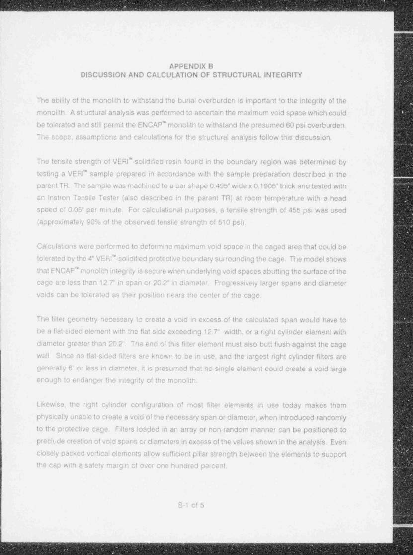
| The ability of the monolith to withstand the burial overburden is important to the integrity of the

monolith. A structural analysis was performed to ascertain the maximum void space which could

be tolerated and still permit the ENCAP' monolith to withstand the presumed 60 psi overburden.

The scope, assumptions and calculations for the strugtural analysis follow this discussion..

The tensile strength of VERl' solidified resin found in the boundary region was determined by

testing a VERl' sample prepared in accordance with the sample preparation described in the

parent TR. The sample was machined to a bar shape 0.495" wide x 0.1905" thick and tested with

an Instron Tensile Tester (also described in the parent TR) at room temperature with a head

i speed of 0.05" per minute. For calculational purposes, a tensile strength of 455 psi was used- (approximately 90% of the observed tensile strength of 510 psi),

t!

! Calculations were performed to determine maximum void space in the caged area that could be

f tolerated by the 4" VERl"-solidified protective boundary surrounding the cage. The model shows !L

{ that ENCAP' monolith integrity is secure when underlying void spaces abutting the surface of the

cage are less than 12.7" in span or 20.2"in diameter. Progressively larger spans and diameter jvoids can be tolerated as their position nears the center of the cage. |

The filter geometry necessary to create a void in excess of the calculated span would have to

be a flat-sided element with the flat side exceeding 12.7" width, or a right cylinder element with

|_ diameter greater than 20.2". The end of this filter element must also butt flush against the cage

wall. Since no flat-sided filters are known to be in use, and the largest right cylinder filters are

generally 6" or less in diameter, it is presumed that no single element could create a void large

enough to endanger the integrity of the monolith.

Likewise, the right cylinder configuration of most filter elements in use today makes them

physically unable to create a void of the necessary span or diameter, when introduced randomly

to the protective cage. Filters loaded in an array or non-random manner can be positioned to

preclude creation of void spans or diameters in excess of the values shown in the analysis. Even

closely packed vertical elements allow sufficient pillar strength between the elements to support

the cap with a safety margin of over one hundred percent.

B-1 of 5

_ _ - _ _ _ _ _ - _ _ _ _ - - _ _

. . _ . . ._ . . . . . . . . _ _

|

Based on the rationale presented above, the encapsulation of filter elements with the ENCAP"

process will not create void spaces of sufficient span or diameter to impugn the integrity of the

monolith under pressures created by the overburden of the burial site,

,

!

I

Il

i

,

B-2 of 5

- _ _ - _ _ - _ - _ _ _ _ - _ _ - _ _ _ _ - _ _ - _ _ _ - _ - _ _ - _ - _ _ - _ _ _ _ _ _ _ _ _ _ _ _ _ _ _ _ - _ _ _ _ _ - _ _ _ _ - _ _A

. - ..

I

||

|

%%% TRI NUCLEAR CORP.!

|

P.O. BOX 178(LAKE RD.) * BALLSTON LAKE. NEW YORK 12019Telephone:(518) 399138g -

FAX : (518)399-9586

Diversified TechnologiesVERILINER: Protective Cave

Analysis ofStructuralIntegrity

SIRDr1

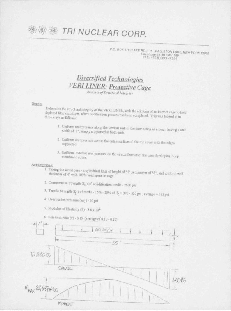
Determine the struct.tralintegrity of the VERI IJNER, with the addition of an interior cage to holddepleted filter cartWges, after # olidification process has been completed. *This was looked at intluee ways as followe

1. Uniform urut pressure along the vertical wall of the liner actmg as a beam having a unitwidth of 1", simply supported at both ends.

2. Uniform unit pressure across the entire surface of the top cover with the edges !

supported.

3. Unifonn, external unit pressure on the circumference of the liner developing hoopmembrane stress.

Annuun119nsi

1. Taking the worst case a cylindricalliner of height of 55", a diameter of $5", and uniform wallthickness of 4" with 100% void space in cage. '|

|

!

2. Compressive Strength (f )of solidificationmedia-2600 psie

I3. Tensile Strength (f[) ofmedia - 15% - 20% of fe = 390 - 520 psi ; average - 455 psi

4. Overburden pressure (wl)- 60 psi

5. Modulus ofElasticity(E) 3.6 x 10'

6. Poisson's ratio (v)- 0.1$ (average of 0.10 - 0.20)_

,

-q /" %I ~l__.F_l w% 1_ i-_;- .;. 7a

jg_

'

_,

k - g| T~ N .',-,

%lb50ltr> N x_L lhw_ i ,

--'

N~rau! II

'

LAlu 86 ras i -

2 ''

r.,

_1_ i ' '

iI

i 3M aar. _ _ _ _ .- _ _ _--

. - . . _ _ _

.

Calculations:

RMaximum shear (V)- wi x 1.= 60 x 55 = 1650 lbs..

2 2

Maximum moment (M) w) x1 =fdL}.5 -22,687.5in Ibs.8 8

Moment ofinertia(1)-bd =J2.4 = 5.333in412 12

f(-M x c = 22.687x 4 = 8508 lbs/In*I 5.333 x 2

No cood because allowable f( is onir 455 lbs4n

f'

Find lencth so that i it s cord.

ft = 455lbs/in' = hiL4 + M = 455 x 5 333 x 2 = 1213 in Ibs5.333 x 2 4

M = 1213 = 60 x 1 + 1 = 1213 x 8 = 12.7 in.8 60

Es (unit stress Ibs/in*)=-3_E (3m + 1) w = 60 lbsTm8

Etrti ti m = 1/v = 6.666t - 4 in

sg(deflection in.) = - 3 W(m-l Y5m+ 1Y1.* a = 27.5 in16XEm t 32

E = 3.6 x 10'

s, = -3(60 x 2376) (3(6.666)+ 1) =3354lbs/in'1

8(3.14)6.666(4 )

s = ._-3(142560Y6.666-1V5(6.666)-41127.5'= 0.24in.2

8(3.14)3.6 x 10*(6.666f(4)3

No rood because_gilowable s, is oniv 455 lbs4n'

Find radius so that :: Is cood:

455 lbs/in*= 3(60 x (314) x r ) (3(6.666) +1).-*r = 10.1 in.

8(3.14)(6 666)(4 )

1

I- l

!

s

|;~

.

9)t

s, (hoop membrane stress)= pRt

a -(60V27.5) = 412.5 lbs/in*g4

'

,

p'(extemal collapsing pressure) =d_ 4 sp'Rsq

R 1+ .

\ \ >h I)p' = _4_ ( 2600 _ \= 332.81bsTm*

27.5 'l+4/ 2600y27.5f '

i( (3.6x10/( 4 //

OK because allowable s, & r>'is < 455 lbsdn

C9pdqvi9m,

Using the VERI Liner in this analyzed configuration; je. the ground overburden pressere of 60 psi, theVERI Liner protective cage filled with depleted filter cartridges, and a 4* solidified wall around the outside

'

of the filter protective cage, the stresses developed by the overburden pressure will not exceed the tensilet

strength cf the solidification media provided there is no void under the outside 4* solid wall greater than a!

12.7 inch span or a 20.2 inch diameter circle under the end covers.,

~

Analysis by: / U~

Dordd Acker

Ch ~2EA ~? c.Approyed by: "--

James Warden

,

>1 - t P --%*


Recommended