Received 29 June 2006, in final form 30 October 2006Published 12 December 2006Online at stacks.iop.org/JMM/17/R1
AbstractThe paper reviews the state-of-the-art of miniaturized tunable lasersconstructed by microelectromechanical systems (MEMS) technology,covering various topics of laser configurations, theoretical studies and somedesign issues, with primary focus on the uniqueness of MEMS tunablelasers in comparison to conventional opto-mechanical counterparts. Furtherstudies have also been presented to investigate the tuning range and stabilityin order to provide a deep understanding of the specialities of MEMS lasersin the sense of physics. The introduction of MEMS has endowed twospecial features to tunable lasers. One is that MEMS facilitates externalcavities at very short (<100 µm) and even extremely short length(<10 µm), leading to unusual tuning behaviors and different designconcerns. The other is that the photolithography of the MEMS processmakes it possible to fabricate gratings/mirrors in arbitrary profiles, whichmay inspire the innovation of new laser configurations that can only berealized by MEMS technology. With further work on integration andpackaging, MEMS lasers would be able to deliver their merits of small size,fast tuning speed, wide tuning range and IC integration compatibility, and tobroaden their applications to many fields.
(Some figures in this article are in colour only in the electronic version)
1. Introduction
With the rapid development of microelectromechanicalsystems (MEMS) technology, miniaturization of externalcavity tunable lasers has recently attracted increasing interestin research and development; some have even led tocommercial success [1–3]. MEMS technology makes useof photolithography to fabricate micromechanical structures,which are able to produce complicated movement with fastresponse, high accuracy and enhanced mechanical stability.Well written reviews on MEMS technology and its applicationscan be found in [4–8]. MEMS have a natural synergismwith external-cavity tunable lasers in various aspects. Forexample, a semiconductor chip is about several hundredmicrons long, close to the overall size of a MEMS device(typically 1 mm, including all the functional parts such as
microactuators and suspensions and so on). The wavelengthof most tunable lasers is about 0.4–2 µm, on the samescale of the MEMS fine feature. Some types of lasersneed a displacement of only about half a wavelength totune over the whole range [1, 2]; such displacement canbe easily obtained using microactuators. In addition, highprecision and stable movement of the MEMS structuresenable fine tuning of the wavelength with high repeatability.Moreover, the micromechanical structures make it feasibleto form very short external cavities (<100 µm), whichcannot be realized using the bulky optical components. Mostapplications such as optical communications and biomedicalstudies require the tunable lasers to have a wide tuning range(>40 nm), continuous or stepwise (i.e., discrete) wavelengthchange, fast speed (<1 ms), high accuracy/repeatability, highreliability/stability, etc. Some further require lightweight,
easy integration and low cost. The introduction of MEMSto tunable lasers brings in significant improvement in most ofthese specifications. The small size of MEMS makes the laserslightweight, portable, easy to form a large array with enhancedmechanical-related properties (e.g., tuning speed, tuningresolution/accuracy and mechanical reliability/stability) incomparison to the conventional lasers. The photolithographyof the MEMS process benefits the lasers in terms of accuratepositioning/alignment, batch fabrication, easy integrationwith IC control/monitor circuits, and potentially low cost.More importantly, the ability to construct short cavity makesit promising to obtain a wide tuning range. In some sense, theMEMS technology is revitalizing the tunable lasers.
A MEMS external-cavity tunable laser could be usedbroadly to describe all the lasers that make use of MEMSstructures for the wavelength change. For example,micromachined movable mirrors have been widely usedin vertical cavity side-emitting lasers (VCSELs) [9, 10].Typically the top and bottom mirrors are two oppositelydoped distributed Bragg reflectors (DBRs) with a cavity layer(consisting of an active layer and an air gap) in between. Thebottom mirror sits on the substrate while the top mirror issuspended by a soft beam, which can be a cantilever beam ora membrane [11, 12]. The air gap can be adjusted by applyingan electrostatic potential to attract down the top mirror. Asa result, it changes the cavity length and eventually tunesthe oscillation wavelength to as far as 30–40 nm [13]. Therapid progress has turned MEMS VCSELs from conceptsinto commercial success [14, 15]. Due to the very shortair gaps, the MEMS VCSELs have no space for opticalcomponents and do not need variant optical configurations.From this point of view, the design concern and actualtuning mechanism of the MEMS VCSELs are quite differentfrom those of the edge-emitting tunable lasers. Since theMEMS VCSEL has been extensively reviewed [13, 16–18],this review will not cover this topic. MEMS rotationalmirrors have also been employed to select a wavelengthfrom an array of distributed feedback (DFB) lasers [19, 20].However, this review narrows down to only edge-emittinglasers that make use of the MEMS technology to constructthe external cavities with the wavelength selectable lasersexcluded.
The terms should also be clarified before further detaileddiscussion. The change of wavelength in the tunable laserscan be realized in two approaches, one is the continuous shiftand the other is mode hopping [21–23]. The form representsthe gradual wavelength change if any one of the modes ofthe laser cavity is monitored. It can happen in either thesingle longitudinal mode lasers or multiple longitudinal modelasers when subjected to external feedback. But generally inthe single mode lasers, continuous shift over a large rangeis the primary target while the mode hopping is suppressed.The latter means the peak mode jumps among the cavitymodes, leading to an abrupt wavelength change. It happensmostly in multimode lasers. Many works did not tell thedifference in claiming the wavelength tuning range [2, 3, 24–32]. For the same amount of continuous shift and modehopping, the technical difficulties are quite different. Foraccurate description of the complicated tuning behaviors of theMEMS tunable lasers, the terms of continuous shift and mode
hopping are used to distinguish the two tuning approaches, andcorrespondingly, shift range and hopping range refer to tuningranges by each of the approaches. The term wavelength tuningremains unchanged, describing the alteration of wavelengthby either of or both the shift and hopping approaches, andthe wavelength tuning range refers to the overall range ofwavelength change.
Prior to MEMS technology, conventionally macroscopictunable lasers have been well developed since their adventin 1964 [33]. Details can be found in numerous reviewarticles and textbooks [21, 22, 34–38], which provide asubstantial technological database for the MEMS lasers.With the progress of MEMS fabrication capability fromwet etching, surface micromachining to deep reactive ionetching (DRIE) [39–41], MEMS tunable lasers have evolvedfrom simple to complicated, from non-continuous tuning tocontinuous tuning, from a small to a large tuning range,from hybrid integration to single-chip integration, etc [1–3].Various configurations have been demonstrated [24–32],differing in many aspects of the external cavity such as theexternal reflectors (i.e., mirrors, etalons, gratings, etc), opticalcoupling systems, laser chips (normally cleaved or coated) andintegration methods (single-chip or hybrid). Some are simplecopycat but a miniaturized version of conventional lasers [3],while the others present something new to a certain extent[1, 2, 24–26, 28–31]. In terms of theory, although the MEMStunable lasers follow the same principles as the conventionalbulky counterparts, laser theories and designs should be re-examined since some parameters cannot be simply scaleddown. For example, MEMS are able to construct a very shortexternal cavity (e.g. <10 µm) [1, 2, 24–26, 31, 32, 42–49],much smaller than the long cavity in bulky tunable lasers(typically >10 cm). In such a short cavity, the wavelengthdependence of the refractive index of the laser gain mediumis no longer negligible [29, 50, 51]. The merits of MEMS donot come at no cost. Some technical challenges have arisen,for example, the optical system and the MEMS packaging.The optical quality of micromachined mirrors/gratings is notcomparable to the conventional ones. It is also difficult tofabricate three-dimensional (3D) optical systems using theMEMS process without additional assembly. Since MEMStunable lasers involve movable micromechanical structures,laser chips, optical fibers and even some external opticalcomponents (e.g., gratings and ball lenses [3, 52–56]), thepackaging and integration would face extreme difficultiesin handling, optical alignment and attachment, and maycause mechanical, electrical and thermal stability/reliabilityproblems. Further discussion of MEMS versus conventionallaser optics in terms of optical functionalities can be found in[57]. The experimental comparison was shown in [31].
The typical configurations of MEMS tunable lasers will beclassified in section 2, with detailed discussions on the meritsand constraints. Theoretical analyses of MEMS lasers will bereviewed in section 3, with further studies on the tuning rangeand tuning stability so as to provide a deep understanding of theuniqueness of MEMS lasers in the sense of physics. Finally,a short discussion will be given on the integration technologyof MEMS lasers.
R2
Topical Review
Laser chip Flatmirror
Laser chip Curved mirror
(a)
(b)
Laser chip Curved mirror
Rod lens
Laser chip FPetalon
(c) (d )
Gain chip Microlens
Blazedgrating
AR
Gain chip MicrolensBlazed grating
Mirror
AR
(e)
( f )
Gain chip Blazedgrating
AR
MirrorPivot
(g)
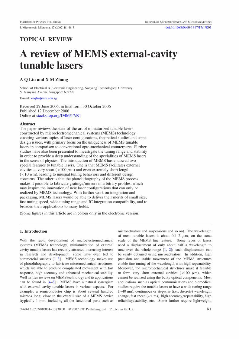
Figure 1. Typical configurations of developed MEMS tunable lasersas classified by external reflectors and micro-optical systems in theexternal cavities. (a) Lensless scheme, a flat mirror as the externalreflector, without any collimation; (b) curved-mirror scheme, acurved mirror to focus in the horizontal direction; (c) 3D-couplingscheme, a curved mirror as the reflector plus a rod lens to focus inthe vertical direction; (d ) Fabry–Perot configuration, an etalon asthe external reflector; (e) Littrow scheme, a blazed grating in theLittrow configuration; ( f ) Littman scheme, a blazed grating in theLittman, and (g) non-standard grating scheme, a blazed gratinghaving variable profile and position of teeth to diffract and collimatethe laser beam simultaneously.
2. Laser configurations
Of the many developed MEMS tunable lasers, the tunabilityis mainly determined by the properties of the external cavity,such as the type of external reflectors, cavity length, feedbackstrength (i.e., coupling efficiency of the external cavity) andmicro-optical system. Below will be discussed the typicallaser configurations and their tuning characteristics. It is notintended to give an exhaustive list of the existing MEMS laserconfigurations, but to merely focus on simple cases so as topresent clear physical pictures.
The common configurations of the developed MEMSlasers are illustrated in figure 1, which has seven differentschemes but can be roughly categorized into three types,the mirror configuration, the Fabry–Perot (FP) configurationand the grating configuration as symbolized by the externalreflectors. The schemes in figures 1(a)–(c) make use ofmirrors as the reflectors; the difference lies in the micro-opticalsystem [1, 2, 24–27, 30, 58–60]. In figure 1(d ), a FPetalon is used to form the external cavity [31, 32, 42–49].
In figures 1(e)–(g), gratings play the key roles in forming theresonant cavity and selecting the wavelength [3, 28, 29, 52–55,61, 62]. In tunable lasers, the reflectors determine the generalbehavior of the laser tenability. For example, the mirror isa non-dispersive element and presents no filtering effect tothe laser beam; if there is no internal wavelength selectionmechanism within the laser cavity, the output commonly hasmultiple longitudinal modes, and thus mode hopping andcompetition can easily happen during the wavelength tuning.In the FP configuration [31, 32, 42–49], the etalon can selecta peak mode while suppressing the others; single longitudinalmode is feasible but mode hopping may happen easily. Thegrating configuration generally employs a blazed grating toselect only one mode to oscillate [3, 28, 29, 52–55, 61, 62].To obtain continuous shift over a large range, a gain chip (i.e.,a FP laser chip with one facet antireflection-coated) is used toprovide optical gain. Once the reflector type is given, the cavitylength and feedback strength will determine more specificallythe performance of the ECTL, for example, tuning range,resolution and tuning behavior (discretely, quasi-continuouslyor continuously, linearly or nonlinearly, stably or chaotically,etc).
2.1. Mirror configuration
It can be seen from figure 1 that the mirror configuration hasa simple structure in comparison to the other two. It is thusparticularly attractive to research and development. As theemitted laser light in the external cavity should be reflectedand then coupled back the internal cavity, it is crucial to haveproper design of optical coupling. Based on the micro-opticalsystem, the previous works can be subcategorized into threedifferent schemes as illustrated in figures 1(a)–(c). Figure 1(a)has no optical component for focusing/collimation (named asthe lensless scheme) [1, 2, 24–26, 31, 58, 59]; figure 1(b)provides focusing in the horizontal direction by simply curvingup the shape of the mirror (named as the curved-mirrorscheme) [27, 60, 63]; and figure 1(c) further improves thefocusing/collimation by introducing an additional rod lens (orcylindrical lens, can be implemented by a piece of opticalfiber); it thus enables optical coupling in 3D space (named asthe 3D-coupling scheme). The sequence of figures 1(a)–(c)also represents the technical evolution of this type of MEMSlaser. The different choices of micro-optical system determinethe obtainable length of the external cavity, and affect thetunability of the lasers. More discussions will be presentedlater in the theoretical analysis part.
2.1.1. Lensless scheme. This is the simplest configuration,without any focusing component in the external cavity. As thelaser beam emitted from the end facet has a small spot sizeand a large divergence angle, the length of the external cavityshould be chosen very short so as to maintain an acceptablefeedback efficiency. Typically, the emitted Gaussian beamhas an elliptical shape with beam waist radii of about 1.0–2.5 µm in the horizontal direction and 0.5–1.8 µm in thevertical direction, while the half divergence angle is commonly15–40◦. Estimations of the coupling efficiency ηext (in termsof optical power, or intensity) with the change of the externalcavity length L are plotted in figure 2, with two cases in the
R3
Topical Review
0.0
0.2
0.4
0.6
0.8
1.0
0 5 10 15 20
External cavity length L (µm)
Cou
plin
g ef
ficie
ncy
r (
n.u.
)
0
0.6
1.2
1.8
2.4
3
Effe
ctiv
e le
ngth
r*L
(µm
)
A
C
B
D
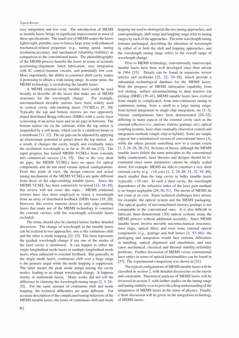
Figure 2. Variations of the coupling efficiency and the effectiveexternal cavity length with change of the real external cavity length.The curves labeled A and B are estimated according to the laserparameters of [2], while C and D are of [31]. n.u. stands for no unit.
literature as the examples. In one case (curves A and B),the laser parameters are from [2], in which the wavelengthis 1538 nm and the beam radii are 1.75 µm and 1.53 µm.The other case (curves C and D) is from [31], in which thelaser parameters are 980 nm, 2.5 µm and 0.6 µm, respectively.It is assumed in the estimation that the external reflector has100% reflectivity and perfect alignment to the laser chip. Thecalculation is based on the mode coupling method developedin [64], which takes into account the divergence and phasechange of the Gaussian beam during the propagation. It can beseen in curves A and C that the coupling efficiency decreasesrapidly with longer cavity length. At a 5 µm length, thecoupling efficiencies have already dropped to 53% and 21%for the two cases, respectively; at 10 µm, they are 22% and10%; while at 20 µm, they are as low as only 7% and 4%.Curve A is always higher than C, implying better couplingfor the laser beam that has the larger beam size (relative towavelength). This explains why the developed MEMS laserswith the lensless scheme always have very short cavity lengths(<20 µm, typically 5–10 µm). Curves B and D in figure 2represent the product ηext∗L, which determines the tuningrange and will be elaborated later.
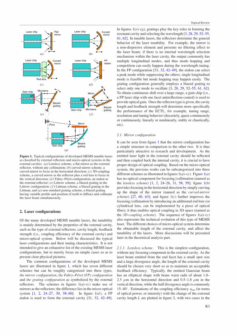
As a MEMS has some difficulty in constructing a high-quality micro-optical system in the external cavity, especiallywhen the structures are fabricated by the deep etching process,the lensless mirror configuration was historically the primarychoice of many early MEMS lasers. For example, suchconfiguration was used to detect the resonance of a cantileverbeam in 1993 [1]. As shown in the schematic diagram infigure 3(a), a freely suspended cantilever microbeam issandwiched between two FP laser diodes; all are etched onthe same GaAs substrate. One laser diode (LD2) emits anintense pulsed laser to shine on the sidewall of the cantilever.As a result, the induced thermal stress forces the cantilever tovibrate. Maximum vibration amplitude can be obtained whenthe driving frequency coincides with the resonant frequencyof the cantilever. The other laser diode (LD1) emits weak butcontinuous laser light. It makes use of the other side of thecantilever as the external mirror to form an external cavity,with a separation of only 3 µm. The cantilever vibrationalters the cavity length; consequently, the output power of
(a)
(b)
(c)
Laserchip
Fiber
Curvedmirror
Photodiode (PD)
Laser diode (LD1)
Laser diode(LD2)
Cantilever microbeam(MB)
Composite cavities fordetecting vibration
Light beam forexciting vibration
Ridge
Figure 3. MEMS tunable lasers in the mirror configuration.(a) Lensless scheme [1]; (b) curved mirror scheme [27] and(c) 3D-microsystem scheme [30]. Part (a) reprinted with permissionfrom Ukita et al 1993 Science 260 786–9. Copyright 1993 AAAS.
LD1 is varied with the wavelength. In this way, the powerchange directly represents the vibration amplitude. Althoughwavelength tuning is not the focus of the work, it had fullsense of a real MEMS tunable laser such as the use of externalcavity and the change of wavelength. Application of this ideawas also proposed to optical disk reading [24]. In 1995 and1996, the same research group presented further works onwavelength tuning [25, 26]. One utilized an anisotropicallyetched silicon cantilever beam as the mirror (no metal coating),10 µm away from a cleaved LD facet [25]. A hoppingrange of about 3 nm was obtained by a discrete interval of0.3 nm. Nonlinear movement of the cantilever was producedby a parallel capacitor actuator. In the other work [26], manyimprovements were made compared with the previous one.The mirror was fabricated by nickel plating, which had higherreflectance. The external cavity was shortened to 5 µm forhigher coupling efficiency. Antireflection (AR) coating wasapplied to the laser facet that faced the nickel mirror, leadingto better spectral purity. A comb drive actuator was usedto translate the nickel mirror, providing linear and precisiondisplacement and thus accurate wavelength tuning. As aconsequence of the improvement, it reported a wavelengthchange of 20 nm by combination of mode hopping andcontinuous shift (∼1 nm range at a 0.01 nm accuracy). Asurface-micromachined mirror was also proposed for tunablelasers [65]. A prototype was demonstrated in 2001 [2] in
R4
Topical Review
which an in-plane polysilicon mirror was assembled in thevertical direction and then integrated with a laser chip, with anexternal cavity length of only 10 µm. A wavelength changeof 16 nm was obtained by an alternation of continuous tuningand mode hopping.
Compared with the etched and electroplated mirrors,the surface-micromachined mirror has more flexibility in themirror size and the optical axis height. However, painstakingmanual assembly has to be involved to lift up and fix themirror to the desired position and angle. Besides, the mirrorquality is not ideal due to the etching holes, the residue-stress-induced bending of the mirror and the surface roughness.Generally speaking, these problems make the surface methodless attractive. If the mirror quality is the greatest concern,a quick way is to use the polished top surface of a siliconcrystalline silicon layer in the silicon-on-insulator (SOI) waferas the mirror, like in many optical scanners [66, 67]. However,assembly and integration become challenging as the laser chipsshould be arranged out of the wafer substrate, and it may bedifficult to translate the mirror to have a significant change inthe laser cavity length. DRIE was also employed to fabricateflat mirrors using the sidewall of etching structures [60]. Thisfabrication presents some advantages over the other methods.As the etching can be quite deep (typically 75 µm), the MEMSstructures are robust and stable. It is convenient to patternthe optical components (mirrors and gratings) to complicatedprofiles. As the mirrors are out of plane after fabrication,no assembly is needed, and the laser chips, optical fibers andother components can be put on the same substrate to facilitatethe single-chip integration. There are also some constraintsof DRIE. For example, the surface of an etched sidewall isquite rough (typically root mean square roughness 40 nm); thevertical etching has restricted depth, which in turn limits themirror size in the vertical direction; and the etching can onlyproduce a straight sidewall, that is, no curvature in the verticaldirection for laser collimation. However, such constraints canbe lifted off. The progress of equipment and process recipeshas been improving the surface quality. The introductionof a micro-optical coupling system into the external cavitywould be able to converge the laser beam in the verticaldirection, solving the problems of mirror size and verticalcollimation. For these reasons, the curved-mirror scheme andthe 3D-coupling scheme have been proposed for the deep-etched MEMS structures.
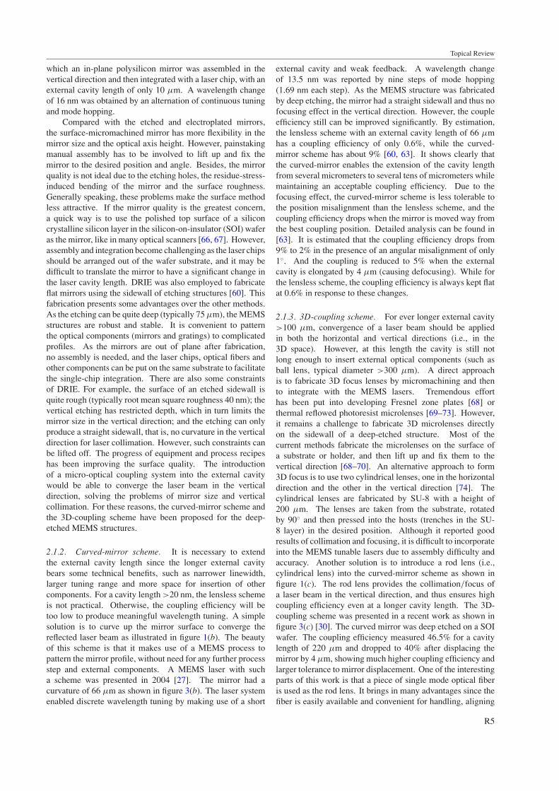
2.1.2. Curved-mirror scheme. It is necessary to extendthe external cavity length since the longer external cavitybears some technical benefits, such as narrower linewidth,larger tuning range and more space for insertion of othercomponents. For a cavity length >20 nm, the lensless schemeis not practical. Otherwise, the coupling efficiency will betoo low to produce meaningful wavelength tuning. A simplesolution is to curve up the mirror surface to converge thereflected laser beam as illustrated in figure 1(b). The beautyof this scheme is that it makes use of a MEMS process topattern the mirror profile, without need for any further processstep and external components. A MEMS laser with sucha scheme was presented in 2004 [27]. The mirror had acurvature of 66 µm as shown in figure 3(b). The laser systemenabled discrete wavelength tuning by making use of a short
external cavity and weak feedback. A wavelength changeof 13.5 nm was reported by nine steps of mode hopping(1.69 nm each step). As the MEMS structure was fabricatedby deep etching, the mirror had a straight sidewall and thus nofocusing effect in the vertical direction. However, the coupleefficiency still can be improved significantly. By estimation,the lensless scheme with an external cavity length of 66 µmhas a coupling efficiency of only 0.6%, while the curved-mirror scheme has about 9% [60, 63]. It shows clearly thatthe curved-mirror enables the extension of the cavity lengthfrom several micrometers to several tens of micrometers whilemaintaining an acceptable coupling efficiency. Due to thefocusing effect, the curved-mirror scheme is less tolerable tothe position misalignment than the lensless scheme, and thecoupling efficiency drops when the mirror is moved way fromthe best coupling position. Detailed analysis can be found in[63]. It is estimated that the coupling efficiency drops from9% to 2% in the presence of an angular misalignment of only1◦. And the coupling is reduced to 5% when the externalcavity is elongated by 4 µm (causing defocusing). While forthe lensless scheme, the coupling efficiency is always kept flatat 0.6% in response to these changes.
2.1.3. 3D-coupling scheme. For ever longer external cavity>100 µm, convergence of a laser beam should be appliedin both the horizontal and vertical directions (i.e., in the3D space). However, at this length the cavity is still notlong enough to insert external optical components (such asball lens, typical diameter >300 µm). A direct approachis to fabricate 3D focus lenses by micromachining and thento integrate with the MEMS lasers. Tremendous efforthas been put into developing Fresnel zone plates [68] orthermal reflowed photoresist microlenses [69–73]. However,it remains a challenge to fabricate 3D microlenses directlyon the sidewall of a deep-etched structure. Most of thecurrent methods fabricate the microlenses on the surface ofa substrate or holder, and then lift up and fix them to thevertical direction [68–70]. An alternative approach to form3D focus is to use two cylindrical lenses, one in the horizontaldirection and the other in the vertical direction [74]. Thecylindrical lenses are fabricated by SU-8 with a height of200 µm. The lenses are taken from the substrate, rotatedby 90◦ and then pressed into the hosts (trenches in the SU-8 layer) in the desired position. Although it reported goodresults of collimation and focusing, it is difficult to incorporateinto the MEMS tunable lasers due to assembly difficulty andaccuracy. Another solution is to introduce a rod lens (i.e.,cylindrical lens) into the curved-mirror scheme as shown infigure 1(c). The rod lens provides the collimation/focus ofa laser beam in the vertical direction, and thus ensures highcoupling efficiency even at a longer cavity length. The 3D-coupling scheme was presented in a recent work as shown infigure 3(c) [30]. The curved mirror was deep etched on a SOIwafer. The coupling efficiency measured 46.5% for a cavitylength of 220 µm and dropped to 40% after displacing themirror by 4 µm, showing much higher coupling efficiency andlarger tolerance to mirror displacement. One of the interestingparts of this work is that a piece of single mode optical fiberis used as the rod lens. It brings in many advantages since thefiber is easily available and convenient for handling, aligning
R5
Topical Review
Bottommirror
Topmirror
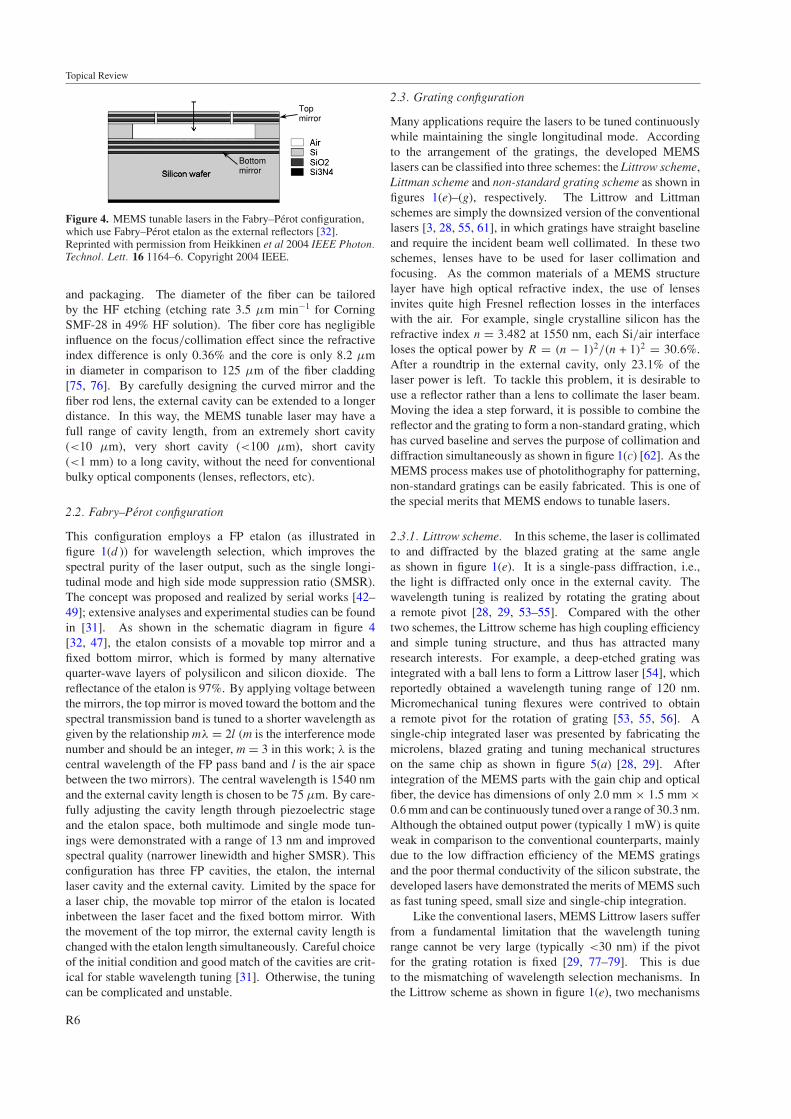
Figure 4. MEMS tunable lasers in the Fabry–Perot configuration,which use Fabry–Perot etalon as the external reflectors [32].Reprinted with permission from Heikkinen et al 2004 IEEE Photon.Technol. Lett. 16 1164–6. Copyright 2004 IEEE.
and packaging. The diameter of the fiber can be tailoredby the HF etching (etching rate 3.5 µm min−1 for CorningSMF-28 in 49% HF solution). The fiber core has negligibleinfluence on the focus/collimation effect since the refractiveindex difference is only 0.36% and the core is only 8.2 µmin diameter in comparison to 125 µm of the fiber cladding[75, 76]. By carefully designing the curved mirror and thefiber rod lens, the external cavity can be extended to a longerdistance. In this way, the MEMS tunable laser may have afull range of cavity length, from an extremely short cavity(<10 µm), very short cavity (<100 µm), short cavity(<1 mm) to a long cavity, without the need for conventionalbulky optical components (lenses, reflectors, etc).
2.2. Fabry–Perot configuration
This configuration employs a FP etalon (as illustrated infigure 1(d )) for wavelength selection, which improves thespectral purity of the laser output, such as the single longi-tudinal mode and high side mode suppression ratio (SMSR).The concept was proposed and realized by serial works [42–49]; extensive analyses and experimental studies can be foundin [31]. As shown in the schematic diagram in figure 4[32, 47], the etalon consists of a movable top mirror and afixed bottom mirror, which is formed by many alternativequarter-wave layers of polysilicon and silicon dioxide. Thereflectance of the etalon is 97%. By applying voltage betweenthe mirrors, the top mirror is moved toward the bottom and thespectral transmission band is tuned to a shorter wavelength asgiven by the relationship mλ = 2l (m is the interference modenumber and should be an integer, m = 3 in this work; λ is thecentral wavelength of the FP pass band and l is the air spacebetween the two mirrors). The central wavelength is 1540 nmand the external cavity length is chosen to be 75 µm. By care-fully adjusting the cavity length through piezoelectric stageand the etalon space, both multimode and single mode tun-ings were demonstrated with a range of 13 nm and improvedspectral quality (narrower linewidth and higher SMSR). Thisconfiguration has three FP cavities, the etalon, the internallaser cavity and the external cavity. Limited by the space fora laser chip, the movable top mirror of the etalon is locatedinbetween the laser facet and the fixed bottom mirror. Withthe movement of the top mirror, the external cavity length ischanged with the etalon length simultaneously. Careful choiceof the initial condition and good match of the cavities are crit-ical for stable wavelength tuning [31]. Otherwise, the tuningcan be complicated and unstable.
2.3. Grating configuration
Many applications require the lasers to be tuned continuouslywhile maintaining the single longitudinal mode. Accordingto the arrangement of the gratings, the developed MEMSlasers can be classified into three schemes: the Littrow scheme,Littman scheme and non-standard grating scheme as shown infigures 1(e)–(g), respectively. The Littrow and Littmanschemes are simply the downsized version of the conventionallasers [3, 28, 55, 61], in which gratings have straight baselineand require the incident beam well collimated. In these twoschemes, lenses have to be used for laser collimation andfocusing. As the common materials of a MEMS structurelayer have high optical refractive index, the use of lensesinvites quite high Fresnel reflection losses in the interfaceswith the air. For example, single crystalline silicon has therefractive index n = 3.482 at 1550 nm, each Si/air interfaceloses the optical power by R = (n − 1)2/(n + 1)2 = 30.6%.After a roundtrip in the external cavity, only 23.1% of thelaser power is left. To tackle this problem, it is desirable touse a reflector rather than a lens to collimate the laser beam.Moving the idea a step forward, it is possible to combine thereflector and the grating to form a non-standard grating, whichhas curved baseline and serves the purpose of collimation anddiffraction simultaneously as shown in figure 1(c) [62]. As theMEMS process makes use of photolithography for patterning,non-standard gratings can be easily fabricated. This is one ofthe special merits that MEMS endows to tunable lasers.
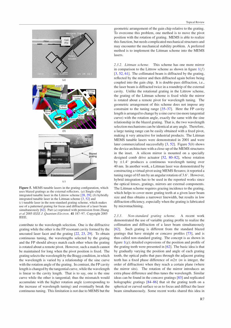
2.3.1. Littrow scheme. In this scheme, the laser is collimatedto and diffracted by the blazed grating at the same angleas shown in figure 1(e). It is a single-pass diffraction, i.e.,the light is diffracted only once in the external cavity. Thewavelength tuning is realized by rotating the grating abouta remote pivot [28, 29, 53–55]. Compared with the othertwo schemes, the Littrow scheme has high coupling efficiencyand simple tuning structure, and thus has attracted manyresearch interests. For example, a deep-etched grating wasintegrated with a ball lens to form a Littrow laser [54], whichreportedly obtained a wavelength tuning range of 120 nm.Micromechanical tuning flexures were contrived to obtaina remote pivot for the rotation of grating [53, 55, 56]. Asingle-chip integrated laser was presented by fabricating themicrolens, blazed grating and tuning mechanical structureson the same chip as shown in figure 5(a) [28, 29]. Afterintegration of the MEMS parts with the gain chip and opticalfiber, the device has dimensions of only 2.0 mm × 1.5 mm ×0.6 mm and can be continuously tuned over a range of 30.3 nm.Although the obtained output power (typically 1 mW) is quiteweak in comparison to the conventional counterparts, mainlydue to the low diffraction efficiency of the MEMS gratingsand the poor thermal conductivity of the silicon substrate, thedeveloped lasers have demonstrated the merits of MEMS suchas fast tuning speed, small size and single-chip integration.
Like the conventional lasers, MEMS Littrow lasers sufferfrom a fundamental limitation that the wavelength tuningrange cannot be very large (typically <30 nm) if the pivotfor the grating rotation is fixed [29, 77–79]. This is dueto the mismatching of wavelength selection mechanisms. Inthe Littrow scheme as shown in figure 1(e), two mechanisms
R6
Topical Review
(b)
(a)
(c)
Blazedgrating
Fiber
Gain chip
Mirror
100 um
Figure 5. MEMS tunable lasers in the grating configuration, whichuses blazed gratings as the external reflectors. (a) Single-chipintegrated tunable laser in the Littrow scheme [28, 29]; (b) hybridlyintegrated tunable laser in the Littman scheme [3, 52] and(c) tunable laser in the non-standard grating scheme, which makesuse of a patterned grating for focus and diffraction of a laser beamsimultaneously [62]. Part (a) reprinted with permission from Zhanget al 2005 IEEE J. Quantum Electron. 41 187–97. Copyright 2005IEEE.
contribute to the wavelength selection. One is the diffractivegrating while the other is the FP resonant cavity formed by theuncoated laser facet and the grating [22, 23, 29]. To obtaincontinuous tuning, the wavelengths selected by the gratingand the FP should always match each other when the gratingis rotated about a remote pivot. However, such a match cannotbe maintained for long when the pivot position is fixed. Thegrating selects the wavelength by the Bragg condition, in whichthe wavelength is varied by a relationship of the sine curvewith the rotation angle of the grating. In contrast, the FP cavitylength is changed by the tangential curve, while the wavelengthis linear to the cavity length. That is to say, one is the sinecurve while the other is tangential; thus the mismatch wouldaccumulate with the higher rotation angle (corresponding tothe increase of wavelength tuning) and eventually break thecontinuous tuning. This limitation is not due to MEMS but the
geometric arrangement of the gain chip relative to the grating.To overcome this problem, one method is to move the pivotposition with the rotation of grating. MEMS is able to realizethis function, but needs complicated mechanical structures andmay encounter the mechanical stability problem. A preferredmethod is to implement the Littman scheme into the MEMSlasers.
2.3.2. Littman scheme. This scheme has one more mirrorin comparison to the Littrow scheme as shown in figure 1( f )[3, 52, 61]. The collimated beam is diffracted by the grating,reflected by the mirror and then diffracted again before beingcoupled into the gain chip. It is double-pass diffraction, i.e.,the laser beam is diffracted twice in a roundtrip of the externalcavity. Unlike the rotational grating in the Littrow scheme,the grating of the Littman scheme is fixed while the mirroris rotated about a remote pivot for wavelength tuning. Thegeometric arrangement of this scheme does not impose anyconstraint to the tuning range [35–37]. Here the FP cavitylength is arranged to change by a sine curve (no more tangentialcurve) with the rotation angle, exactly the same with the sinerelationship in the blazed grating. That is, the two wavelengthselection mechanisms can be identical at any angle. Therefore,a large tuning range can be easily obtained with a fixed pivot,making it very attractive for industrial products. The LittmanMEMS tunable lasers were demonstrated in 2001 and werelater commercialized successfully [3, 52]. Figure 5(b) showsthe device architecture with a close-up of the MEMS structuresin the inset. A silicon mirror is mounted on a speciallydesigned comb drive actuator [52, 80–82], whose rotationby ±1.4◦ produces a continuous wavelength tuning over40 nm. In another work, a Littman laser was demonstrated byconstructing a virtual pivot using MEMS flexures; it reported atuning range of 65 nm by an angular rotation of 3.6◦. However,hybrid integration has to be used in the reported works sincethe optical lenses, gratings, mirrors are external components.The Littman scheme requires grazing incidence to the grating,which helps to cover more grating teeth at a given laser beamsize and thus obtains a narrower linewidth, but results in lowdiffraction efficiency, especially when the grating is fabricatedby micromachining.
2.3.3. Non-standard grating scheme. A recent workdemonstrated the use of variable grating profile to realize thecollimation and diffraction of a laser beam simultaneously[62]. Such grating is different from the standard blazedgratings that have straight or concave profiles [73], and isthus called non-standard grating. The concept is as shown infigure 1(g); detailed expressions of the position and profile ofthe grating teeth were presented in [62]. The basic idea is thatby gradually varying the position and angle of each gratingtooth, the optical paths that pass through the adjacent gratingteeth has a fixed phase difference of m2π (m is integer, theorder of diffraction) when they reach a certain plane (wherethe mirror sits). The rotation of the mirror introduces anextra phase difference and thus tunes the wavelength. Similarideas can be found in the concave gratings [83] and replicatedholographic gratings [84–86] that sit the grating teeth on aspherical or curved surface so as to focus and diffract the laserbeam simultaneously. Some recent works shared this idea in
R7
Topical Review
patterning the planar waveguide to form lenses and gratingsfor tunable lasers, though the tuning is not based on MEMSbut on the refractive index change by the injected electricalcurrent [87, 88].
The MEMS device is shown in figure 5(c). The tuningstructure is fabricated by deep etching on a SOI wafer, and isthen integrated with the gain chip and optical fiber onto a singlechip, with a footprint of only 3 mm × 2.5 mm. The gratingteeth have varying position and profile, but share the sameperiod of 3.32 µm if projected to the equiphase plane (i.e., themirror surface). It reported a tuning range of 9.2 nm. Thisparticular design does not need a lens for collimation, and thuscircumvents the losses induced by the micromachined lensesor the extra assembly of external lenses. In addition, it avoidsthe use of grazing incidence to the grating, which causes lowdiffraction efficiency in the Littman scheme. Although thetuning range is quite limited in the reported work [62], itdemonstrates the potential of MEMS in enabling new lasertuning configurations, which is not practical for conventionallasers due to the fabrication difficulty of gratings.
3. Theoretical development
MEMS tunable lasers follow the same general physicalprinciples as the conventional ones, which have beenextensively analyzed and reviewed in [38, 89, 90]. However,MEMS tunable lasers may exhibit certain uniqueness inthe aspects of tuning behaviors and design considerationssince the MEMS technology provides different workingconditions such as short cavity length and high couplingefficiency. For instance, the extremely short cavity length(<10 µm) of the MEMS lasers makes it feasible to obtaina large hopping range in the mirror configuration [63], whichcannot be realized by the conventional lasers with a long cavitylength (>1 cm). For this reason, efforts have been made torevisit the laser theories and to adapt them to the MEMS cases[29, 59]. This section will try to summarize the previoustheoretical works and further develop them for studying thetuning range and tuning stability.
3.1. Tuning range and stability of mirror configuration
The short cavity length and the high coupling efficiency arethe dominant factors that distinguish the MEMS lasers fromthe conventional ones in terms of tuning behaviors such as thecontinuous tuning range, stability of tuning and mode hoppingrange. Generally, single mode lasers focus on continuoustuning, while multimode lasers target at discrete tuning (i.e.,controllable mode hopping with well suppressed continuousshift).
3.1.1. Continuous shift. In the presence of externalreflection, the output wavelength of the laser will be shiftedwith the change of the external cavity length. Under weakfeedback strength, such wavelength shift �λ was derived in[38, 89], as given by
�λ = λ20
2πL
C sin[2πτLν0 + arctan(α)]
1 + C cos[2πτLν0 + arctan(α)](1)
where λ0 and ν0 are the central wavelength and frequency,respectively; L is the external cavity length; τ L is the roundtrip
delay of the external cavity given by τL = 2L/c0 (c0 denotesthe light velocity in vacuum); α is the equivalent linewidthenhancement factor given by α = α0/�0 (α0 is the linewidthenhancement factor of the gain medium and �0 is the opticalconfinement factor); and C = (L/µ0d0)ξ
√1 + α2 represents
the external feedback strength, where µ0 is the refractive indexof the laser gain medium, d0 is the length of the internal lasercavity, ξ = r3
(1 − r2
2
)/r2 is the relative reflectance of the
external mirror, and r3 and r2 are the amplitude reflectanceof the external mirror and the laser facet facing the externalmirror, respectively. Here r3 is not directly the reflectance ofthe mirror but the coupling efficiency of the external cavity,with mirror reflectance and coupling losses (due to the mirrormisalignment and the spreading of a laser beam) taken intoconsideration. A correction is made to include the influenceof the optical confinement factor �0, which has a small value(typically 0.05–0.1 for ridge-waveguide multiple-quantum-well InGaAsP/InP lasers) and significant influence to thetuning range but was overlooked in some previous analyses[38, 59, 89].
Equation (1) describes the basic relationship between thecontinuous shift and the change of the external cavity length.It should be highlighted that the derivation of equation (1) isbased on one explicit assumption ξ � 1 (called the weakfeedback condition) and two implicit assumptions: one isthat the laser is single longitudinal mode (called the singlemode condition) and the other is τL�ν � 1 (called thesmall tuning condition), where �ν = c0�λ
/λ2
0 is the shiftof central frequency. These three conditions define theapplicability of the analysis. In MEMS lasers, they shouldbe re-examined. The small tuning condition is equivalent�λ � λ2
0
/2L, i.e., the tuning range is limited by the free
spectral range (FSR) of the external cavity. It implies thatthe short cavity allows a larger tuning range. Under thesingle mode condition, the laser tuning is continuous withthe increase of the external cavity, at a period of half awavelength. However, when this condition is broken, thetuning behavior becomes complicated. This explains whythe experiments observe a combination of continuous tuningand mode hopping when multiple longitudinal lasers are used[2, 25, 26, 31]. The weak feedback condition ξ � 1 requiresr3 � r2, that is, the feedback from the external mirror isrelatively weak in comparison to the laser facet reflection.This is why the model is called the weak feedback model. Anextension of the model was presented to cover both the weakand medium feedback regions based on the assumption thatr2r3 � 1 [59]. This model is more suitable for some MEMSlasers, especially those having extremely short cavity and highfeedback coupling efficiency. For instance, it can be read fromfigure 23 of [31] that r3 = 0.3–0.4 when the external cavityis 5–10 µm. If the laser facets are normally cleaved, then ithas ξ ≈ 0.45, which is no longer a weak feedback. With thesame parameters, r2r3 ≈ 0.18, the condition of r2r3 � 1 isheld roughly. In this case, the extended feedback model hasto be used.
One of most important parameters of the tunable laser isthe shift range �λr. Based on equation (1), it can be furtherderived that
�λr = λ20
2π
A0√1r2
3− A2
0L2
(2)
R8
Topical Review
0
5
10
15
20
0 0.2 0.4 0.6 0.8 1
Coupling efficiency r 3 (n.u.)
Ran
ge o
f con
tinuo
us s
hift
∆λr
(nm
)
Cavity 10 um
Cavity 66 um
Cavity 220 um
0.0
0.2
0.4
0.6
0.8
1.0
1.2
0 20 40 60 80 100
External cavity length L (µm)
Cou
plin
g ef
ficie
ncy
r (
n.u.
) Upper limit r3 = 1
r2 = 0.55
r2 = 0.20
Unstable
Stable
r2 = 0.70
(a)
(b)
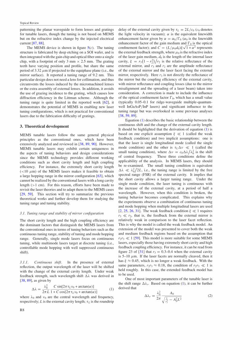
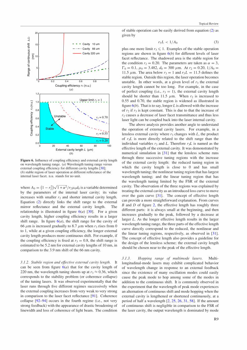
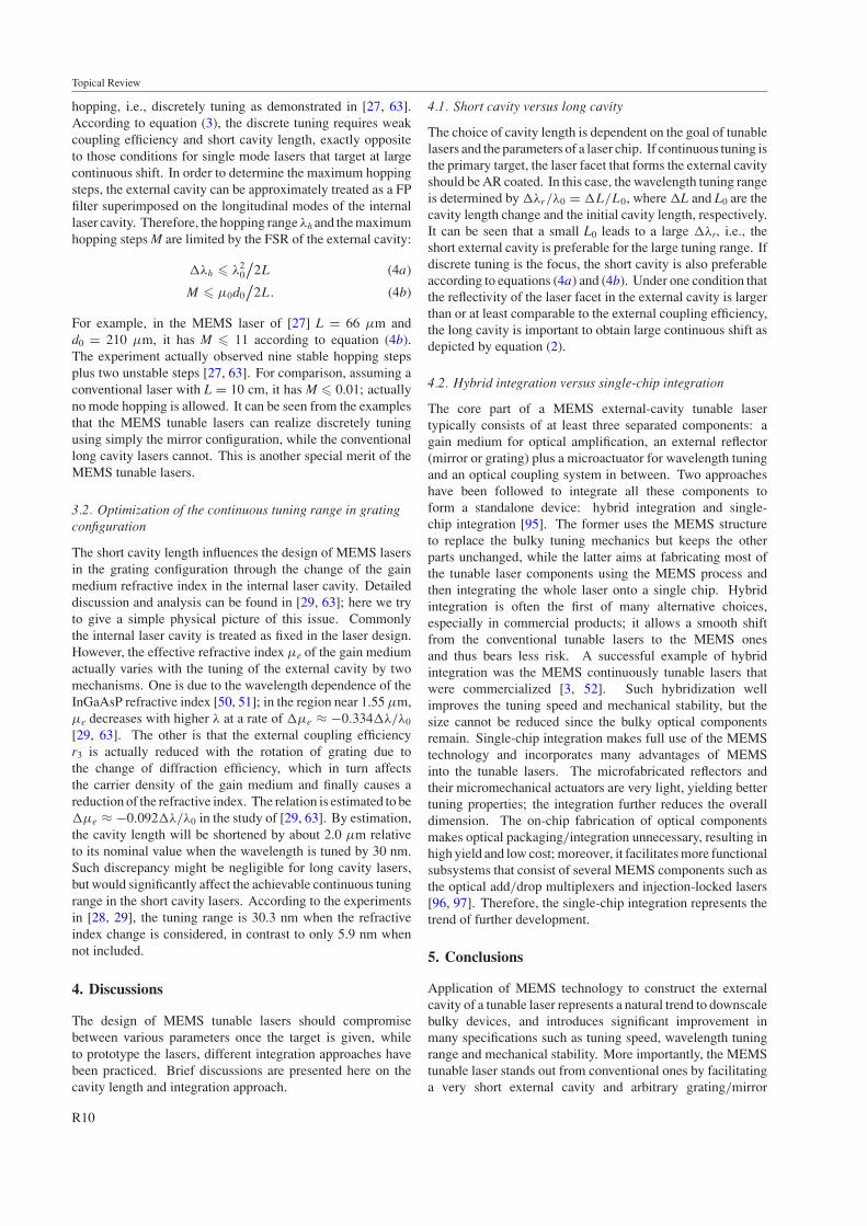
Figure 6. Influence of coupling efficiency and external cavity lengthon wavelength tuning range. (a) Wavelength tuning range versusexternal coupling efficiency for different cavity lengths [30];(b) stable region of laser operation at different reflectance of theinternal laser facet. n.u. stands for no unit.
where A0 = (1 − r2
2
)√1 + α2/r2µ0d0 is a variable determined
by the parameters of the internal laser cavity; its valueincreases with smaller r2 and shorter internal cavity length.Equation (2) directly links the shift range to the externalmirror reflectance and the external cavity length. Therelationship is illustrated in figure 6(a) [30]. For a givencavity length, higher coupling efficiency results in a largershift range. In figure 6(a), the shift range for the cavity of66 µm is increased gradually to 8.7 µm when r3 rises from 0to 1, while at a given coupling efficiency, the longer externalcavity length produces more continuous shift. For example, ifthe coupling efficiency is fixed at r3 = 0.8, the shift range isestimated to be 5.2 nm for external cavity lengths of 10 nm, incomparison to the 3.9 nm shift of the 66 nm cavity.
3.1.2. Stabile region and effective external cavity length. Itcan be seen from figure 6(a) that for the cavity length of220 nm, the wavelength tuning shoots up at r3 ≈ 0.36, whichcorresponds to the stability problem (or coherence collapse)of the tuning lasers. It was observed experimentally that thelaser runs through five different regimes successively whenthe external coupling increases from very weak to very strongin comparison to the laser facet reflectance [91]. Coherencecollapse [92–94] occurs in the fourth regime (i.e., not verystrong feedback) with the appearance of drastic broadening oflinewidth and loss of coherence of light beam. The condition
of stable operation can be easily derived from equation (2) asgiven by
r3L < 1/A0 (3)
plus one more limit r3 � 1. Examples of the stable operationregions are shown in figure 6(b) for different levels of laserfacet reflectance. The shadowed area is the stable region forthe condition r2 = 0.20. The parameters are taken as α = 3,�0 = 0.1, µ0 = 3.482, d0 = 300 µm. At r2 = 0.20, 1/A0 =11.5 µm. The area below r3 = 1 and r3L = 11.5 defines thestable region. Outside this region, the laser operation becomesunstable. In other words, at a given level of r3 the externalcavity length cannot be too long. For example, in the caseof perfect coupling (i.e., r3 = 1), the external cavity lengthshould be shorter than 11.5 µm. When r2 is increased to0.55 and 0.70, the stable region is widened as illustrated infigure 6(b). That is to say, longer L is allowed with the increaseof r2 if r3 is kept constant. This is due to that the increase ofr2 causes a decrease of laser facet transmittance and thus lesslaser light can be coupled back into the laser internal cavity.
The above analysis provides another angle to understandthe operation of external cavity lasers. For example, in alensless external cavity where r3 changes with L, the productof r3L is more directly related to the shift range than theindividual variables r3 and L. Therefore r3L is named as theeffective length of the external cavity. It was demonstrated bynumerical simulation in [31] that the lensless scheme runsthrough three successive tuning regions with the increaseof the external cavity length: the reduced tuning region inwhich the cavity length is close to 0 and has smallwavelength tuning; the nonlinear tuning region that has largestwavelength tuning; and the linear tuning region that hasthe wavelength tuning limited by the FSR of the externalcavity. The observation of the three regions was explained bytreating the external cavity as an introduced loss curve to moveover the gain curve [31]. The concept of effective lengthcan provide a more straightforward explanation. From curvesB and D of figure 2, the effective length has roughly threedifferent parts: it is always small at the beginning, and thenincreases gradually to the peak, followed by a decrease atlarger L. As the longer effective length results in the largerwavelength tuning range, the three parts of the effective lengthcurve directly correspond to the reduced, the nonlinear andthe linear tuning regions, respectively, as observed in [31].The concept of effective length also provides a guideline forthe design of the lensless scheme; the external cavity lengthshould be chosen near to the peak of the effective length.
3.1.3. Hopping range of multimode lasers. Multi-longitudinal-mode lasers may exhibit complicated behaviorof wavelength change in response to an external feedbacksince the existence of many oscillation modes could easilycause the peak mode to hop among some of the modes inaddition to the continuous shift. It is commonly observed inthe experiment that the wavelength of peak mode experiencesan alternation of continuous shift and mode hopping when theexternal cavity is lengthened or shortened continuously, at aperiod of half a wavelength [2, 25, 26, 31, 58]. If the amountof continuous shift is negligible in comparison to the FSR ofthe laser cavity, the output wavelength is dominated by mode
R9
Topical Review
hopping, i.e., discretely tuning as demonstrated in [27, 63].According to equation (3), the discrete tuning requires weakcoupling efficiency and short cavity length, exactly oppositeto those conditions for single mode lasers that target at largecontinuous shift. In order to determine the maximum hoppingsteps, the external cavity can be approximately treated as a FPfilter superimposed on the longitudinal modes of the internallaser cavity. Therefore, the hopping range λh and the maximumhopping steps M are limited by the FSR of the external cavity:
�λh � λ20
/2L (4a)
M � µ0d0/
2L. (4b)
For example, in the MEMS laser of [27] L = 66 µm andd0 = 210 µm, it has M � 11 according to equation (4b).The experiment actually observed nine stable hopping stepsplus two unstable steps [27, 63]. For comparison, assuming aconventional laser with L = 10 cm, it has M � 0.01; actuallyno mode hopping is allowed. It can be seen from the examplesthat the MEMS tunable lasers can realize discretely tuningusing simply the mirror configuration, while the conventionallong cavity lasers cannot. This is another special merit of theMEMS tunable lasers.
3.2. Optimization of the continuous tuning range in gratingconfiguration
The short cavity length influences the design of MEMS lasersin the grating configuration through the change of the gainmedium refractive index in the internal laser cavity. Detaileddiscussion and analysis can be found in [29, 63]; here we tryto give a simple physical picture of this issue. Commonlythe internal laser cavity is treated as fixed in the laser design.However, the effective refractive index µe of the gain mediumactually varies with the tuning of the external cavity by twomechanisms. One is due to the wavelength dependence of theInGaAsP refractive index [50, 51]; in the region near 1.55 µm,µe decreases with higher λ at a rate of �µe ≈ −0.334�λ/λ0
[29, 63]. The other is that the external coupling efficiencyr3 is actually reduced with the rotation of grating due tothe change of diffraction efficiency, which in turn affectsthe carrier density of the gain medium and finally causes areduction of the refractive index. The relation is estimated to be�µe ≈ −0.092�λ/λ0 in the study of [29, 63]. By estimation,the cavity length will be shortened by about 2.0 µm relativeto its nominal value when the wavelength is tuned by 30 nm.Such discrepancy might be negligible for long cavity lasers,but would significantly affect the achievable continuous tuningrange in the short cavity lasers. According to the experimentsin [28, 29], the tuning range is 30.3 nm when the refractiveindex change is considered, in contrast to only 5.9 nm whennot included.
4. Discussions
The design of MEMS tunable lasers should compromisebetween various parameters once the target is given, whileto prototype the lasers, different integration approaches havebeen practiced. Brief discussions are presented here on thecavity length and integration approach.
4.1. Short cavity versus long cavity
The choice of cavity length is dependent on the goal of tunablelasers and the parameters of a laser chip. If continuous tuning isthe primary target, the laser facet that forms the external cavityshould be AR coated. In this case, the wavelength tuning rangeis determined by �λr/λ0 = �L/L0, where �L and L0 are thecavity length change and the initial cavity length, respectively.It can be seen that a small L0 leads to a large �λr, i.e., theshort external cavity is preferable for the large tuning range. Ifdiscrete tuning is the focus, the short cavity is also preferableaccording to equations (4a) and (4b). Under one condition thatthe reflectivity of the laser facet in the external cavity is largerthan or at least comparable to the external coupling efficiency,the long cavity is important to obtain large continuous shift asdepicted by equation (2).
4.2. Hybrid integration versus single-chip integration
The core part of a MEMS external-cavity tunable lasertypically consists of at least three separated components: again medium for optical amplification, an external reflector(mirror or grating) plus a microactuator for wavelength tuningand an optical coupling system in between. Two approacheshave been followed to integrate all these components toform a standalone device: hybrid integration and single-chip integration [95]. The former uses the MEMS structureto replace the bulky tuning mechanics but keeps the otherparts unchanged, while the latter aims at fabricating most ofthe tunable laser components using the MEMS process andthen integrating the whole laser onto a single chip. Hybridintegration is often the first of many alternative choices,especially in commercial products; it allows a smooth shiftfrom the conventional tunable lasers to the MEMS onesand thus bears less risk. A successful example of hybridintegration was the MEMS continuously tunable lasers thatwere commercialized [3, 52]. Such hybridization wellimproves the tuning speed and mechanical stability, but thesize cannot be reduced since the bulky optical componentsremain. Single-chip integration makes full use of the MEMStechnology and incorporates many advantages of MEMSinto the tunable lasers. The microfabricated reflectors andtheir micromechanical actuators are very light, yielding bettertuning properties; the integration further reduces the overalldimension. The on-chip fabrication of optical componentsmakes optical packaging/integration unnecessary, resulting inhigh yield and low cost; moreover, it facilitates more functionalsubsystems that consist of several MEMS components such asthe optical add/drop multiplexers and injection-locked lasers[96, 97]. Therefore, the single-chip integration represents thetrend of further development.
5. Conclusions
Application of MEMS technology to construct the externalcavity of a tunable laser represents a natural trend to downscalebulky devices, and introduces significant improvement inmany specifications such as tuning speed, wavelength tuningrange and mechanical stability. More importantly, the MEMStunable laser stands out from conventional ones by facilitatinga very short external cavity and arbitrary grating/mirror
R10
Topical Review
profile, which cause different wavelength tuning behaviors anddesign concerns, and enables new laser configurations. Thedeveloped MEMS lasers have been demonstrated in variousdesigns. According to the type of external reflector, themicro-optical system and the arrangement of gratings, theycan be roughly summarized into three configurations andcan be further categorized into seven schemes, each has itsown wavelength tuning characteristics. The theoretical workson MEMS lasers have adapted the ready theories under thecondition of very short external cavity, and have analyzed thetopics of continuous shift, mode hopping tuning stability andchange of gain medium refractive index. MEMS tunable lasersare still young compared with conventional lasers. One of themain challenges is the difficulty of packaging as the MEMSstructures, laser chips, optical fibers and control circuits haveto be integrated. More work should be done before theMEMS lasers are able to provide a single-chip solution forreal applications.
Acknowledgments
The authors gratefully acknowledge the support by theAgency for Science, Technology and Research (A∗STAR) ofSingapore under grant no 042 108 0097. Zhang would liketo thank the Singapore Millennium Foundation (SMF) for theResearch Fellowship. Special thanks go to Dr Jing Li, MrYu Aibin and Ms Hong Cai for their helpful discussions andproviding useful information for this study.
References
[1] Ukita H, Uenishi Y and Tanaka H 1993 A photomicrodynamicsystem with a mechanical resonator monolithicallyintegrated with laser diodes on gallium arsenide Science260 786–9
[2] Liu A Q, Zhang X M, Murukeshan V M and Lam Y L 2001 Anovel device level micromachined tunable laser usingpolysilicon 3D mirror IEEE Photon. Technol. Lett.13 427–9
[3] Berger J D and Anthon D 2003 Tunable MEMS devices foroptical networks Opt. Photon. News 14 42–62
[4] Judy J W 2001 Microelectromechanical systems (MEMS):fabrication, design and applications Smart Mater. Struct.10 1115–34
[5] Walker J S 2000 The future of MEMS in telecommunicationsnetworks J. Micromech. Microeng. 10 R1–7
[6] Lin L Y and Goldstein E L 2002 Opportunities and challengesfor MEMS in lightwave communications IEEE J. Sel. Top.Quantum Electron. 8 163–72
[7] Trimmer W 1996 Micromechanics and MEMS: Classic andSeminal Papers to 1990 (New York: IEEE)
[8] Fujita H 1998 Microactuators and micromachines Proc. IEEE86 1721–32
[9] Chen Q, Cole G D, Bjorlin E S, Kimura T, Wu S, Wang C S,MacDonald N C and Bowers J E 2004 First demonstrationof a MEMS tunable vertical-cavity SOA IEEE Photon.Technol. Lett. 16 1438–40
[10] Cole G D, Bjorlin E S, Chen Q, Chan C-Y, Wu S, Wang C S,MacDonald N C and Bowers J E 2005 MEMS-tunablevertical-cavity SOAs IEEE J. Quantum Electron.41 390–407
[11] Li Y M, Yuen W, Li G S and Chang-Hasnain C J 1998Top-emitting micromechanical VCSEL with a 31.6-nmtuning range IEEE Photon. Technol. Lett. 10 18–20
[12] Larson M C, Massengale A R and Harris J S 1996Continuously tunable micromachined vertical cavitysurface emitting laser with 18 nm wavelength range IEEElectron. Lett. 32 330–2
[13] Chang-Hasnain C J 2000 Tunable VCSEL IEEE J. Sel. Top.Quantum Electron. 6 978–87
[14] Vakhshoori D, Tayebati P, Lu C-C, Azimi M, Wang P,Zhou J-H and Canoglu E 1999 2 mW CW single modeoperation of a tunable 1550 nm vertical cavity surfaceemitting laser with 50 nm tuning range IEE Electron. Lett.35 900–1
[15] Vail E C, Li G S, Yuen W and Chang-Hasnain C J 1996 Highperformance micromechanical tunable vertical cavitysurface-emitting lasers IEE Electron. Lett. 32 1888–9
[16] Chang-Hasnain C J 2000 Widely tunable VCSEL usingMEMS technology Proc. 13th LEOS Annual Meeting (RioGrande, Puerto Rico, 13–17 November 2000) pp 54–5
[17] Syms R R A and Moore D F 2002 Optical MEMS for telecomsMater. Today 5 26–35
[18] Pezeshki B 2001 New approaches to laser tuning Opt. Photon.News 12 34–8
[19] Pezeshki B et al 2002 20-mw widely tunable laser moduleusing DFB array and MEMS selection IEEE Photon.Technol. Lett. 14 1457–9
[20] Souhaite G, Blondeau R, Delepine S, Pellegri O, Vassilakis E,Stellmacher M, Graindorge P and Martin P 2001 16channels, switchable external cavity-basedmulti-wavelength laser for DWDM applications Proc.ECOC’01, 27th European Conf. on Optical Communication(Amsterdam, The Netherlands, 30 September–4 October2001) vol 2 pp 196–7
[22] Duarte F J 1995 Tunable Lasers Handbook (London:Academic)
[23] Ye C 2004 Tunable External Cavity Diode Lasers (Singapore:World Scientific)
[24] Ukita H, Uenishi Y and Katagiri Y 1994 Applications of anextremely short strong-feedback configuration of anexternal-cavity laser diode system fabricated withGaAs-based integration technology Appl. Opt. 33 5557–63
[25] Uenishi Y, Tsugai M and Mehregany M 1995Hybrid-integrated laser-diode micro-external mirrorfabricated by (110) silicon micromachining IEE Electron.Lett. 31 965–6
[26] Uenishi Y, Honma K and Nagaoka S 1996 Tunable laser diodeusing a nickel micromachined external mirror IEE Electron.Lett. 32 1207–8
[27] Zhang X M, Liu A Q, Tang D Y and Lu C 2004 Discretewavelength tunable laser using microelectromechanicalsystems technology Appl. Phys. Lett. 84 329–31
[28] Liu A Q, Zhang X M, Tang D Y and Lu C 2004 Tunable laserusing micromachined grating with continuous wavelengthtuning Appl. Phys. Lett. 85 3684–6
[29] Zhang X M, Liu A Q, Lu C and Tang D Y 2005 Continuouswavelength tuning in micromachined Littrowexternal-cavity lasers IEEE J. Quantum Electron. 41 187–97
[30] Zhang X M, Cai H, Lu C, Chen C K and Liu A Q 2006 Designand experiment of 3-dimensional micro-optical system forMEMS tunable lasers Proc. MEMS 2006, 19th IEEE Int.Conf. Micro Electro Mechanical Systems (Istanbul, Turkey,22–26 January 2006 pp 830–3
[31] Aikio J K 2004 Extremely short external cavity (ESEC) laserdevices VTT publication 529, ESPOO 2004http://www.vtt.fi
[32] Heikkinen V, Aikio J K, Alojoki T, Hiltunen J, Mattila A-J,Ollila J and Karioja P 2004 Single-mode tuning of a1540-nm diode laser using a Fabry-Perot interferometerIEEE Photon. Technol. Lett. 16 1164–6
[33] Crowe J W and Craig R M Jr 1964 GaAs laser linewidthmeasurement by heterodyne detection App. Phys. Lett. 572–4
[34] Coldren L A, Fish G A, Akulova Y, Barton J S,Johansson L and Coldren C W 2004 Tunable semiconductorlasers: a tutorial IEEE J. Lightwave Technol. 22 193–202
[35] Littman M G and Metcalf H J 1978 Spectrally narrow pulseddye laser without beam expander Appl. Opt. 17 2224–7
[36] Littman M G 1978 Single-mode operation ofgrazing-incidence pulsed dye laser Opt. Lett. 3 138–40
[37] Liu K and Littman M G 1981 Novel geometry for single-modescanning of tunable lasers Opt. Lett. 6 117–8
[38] Petermann K 1988 Laser Diode Modulation and Noise(London: Kluwer)
[39] Li J, Liu A Q and Zhang Q X 2006 Tolerance analysis forcomb-drive actuator using DRIE fabrication SensorsActuators A 125 494–503
[40] Li J, Zhang Q X and Liu A Q 2003 Advanced fiber opticalswitches using deep RIE (DRIE) fabrication SensorsActuators A 102 286–95
[41] Li J, Zhang Q X, Liu A Q, Goh W L and Ahn J 2003Technique for preventing stiction and notching effect onsilicon-on-insulator microstructure J. Vac. Sci. Technol.B 21 2530–9
[42] Aikio J K and Karioja P 1999 Wavelength tuning of a laserdiode by using a micromechanical Fabry-Perotinterferometer IEEE Photon. Technol. Lett. 11 1220–2
[43] Aikio J K, Sidorin, Blomberg M and Karioja P 1999Wavelength tunable hybrid laser diode realized by using anelectrostatically tuned silicon micromachined Fabry-Perotinterferometer Proc. SPIE 3625, part of the SPIE Conf. onPhysics and Simulation of Optoelectronics Devices VII (SanJose, CA, 25–29 January 1999) pp 588–97
[44] Aikio J K, Kataja K J and Howe D G 2001 Extremely shortexternal cavity lasers: direct semiconductor laser readoutmodeling by using finite difference time domaincalculations Proc. SPIE 4595, Photonics Systems andApplications (Singapore, 28–30 November 2001) pp 163–73
[45] Aikio J K, Kataja K J, Alajoki T, Karioja P and Howe D G2002 Extremely short external cavity lasers: the use ofwavelength tuning effects in near field sensing Proc. SPIE4640 158–69
[46] Sidorin Y, Blomberg M and Karioja P 1999 Demonstration ofa tunable hybrid laser diode using an electrostaticallytunable silicon micromachined Fabry–Perot interferometerdevice IEEE Photon. Technol. Lett. 11 18–20
[47] Blomberg M, Orpana M and Lehto A 1996 Electrically tunableFabry–Perot interferometer produced by surfacemicromechanical techniques for use in optical materialanalysis US Patent 5 561 523
[48] Sidorin Y and Howe D 1998 Some characteristics of anextremely-shortexternal-cavity laser diode realized by buttcoupling a Fabry–Perot laser diode to a single-mode opticalfiber Appl. Opt. 37 3256–63
[49] Sidorin Y, Karioja P and Blomberg M 1999 Novel tunablelaser diode arrangement with a micromachined siliconfilter: feasibility Opt. Commun. 164 121–7
[50] Burkhand H, Dinges H W and Kuphal E 1982 Opticalproperties of In1−x GaxAsyP1−y, InP, GaAs, and GaPdetermined by ellipsometry J. Appl. Phys. 53 655–62
[51] Broberg B and Lindgren S 1984 Refractive index ofIn1−xGaxAsyP1−y layers and InP in the transparentwavelength region J. Appl. Phys. 55 3376–81
[52] Anthon D, Brerger J D, Drake J, Dutta S, Fennema A, Grade JD, Hrinya S, Ilkov F, Jerman H, King D, Lee H, Tselikov Aand Yasumura K 2002 External cavity diode lasers tunedwith silicon MEMS Proc. OFC 2002, Opt. Fiber Commun.Conf. Exhibit (Anaheim, CL, 17–22 March 2002) pp 97–8
[53] Syms R R A and Lohmann A 2002 Tuning mechanism for aMEMS external cavity laser Proc. Optical MEMS 2002,IEEE/LEOS Int. Conf. Optical MEMS (Lugano,Switzerland, 20–23 August 2002) pp 183–4
[54] Lohmann A and Syms R R A 2003 External cavity laser with avertically etched silicon blazed grating IEEE Photon.Technol. Lett. 15 120–2
[55] Syms R R A and Lohmann A 2003 MOEMS tuning elementfor a Littrow external cavity laser IEEE J.Microelectromech. Syst. 12 921–8
[56] Syms R R A, Lohmann A and Huang W 2005 MOEMS lasertuning element with an indirect drive Proc. Optical MEMS2005, IEEE/LEOS Int. Conf. Optical MEMS (Oulu,Finland, 1–4 August 2005) pp 11–2
[57] Kim S, Barbastathis G and Tuller H L 2004 MEMS for opticalfunctionality J. Electroceram. 12 133–44
[58] Zhang X M, Liu A Q, Murukeshan V M and Chollet F 2002Integrated micromachined tunable lasers for all opticalnetwork (AON) applications Sensors Actuators A97–98 54–60
[59] Liu A Q, Zhang X M, Murukeshan V M, Lu C and Cheng T H2002 Micromachined wavelength tunable laser with anextended feedback model IEEE J. Sel. Top. QuantumElectron. 8 73–9
[60] Liu A Q, Zhang X M, Li J and Lu C 2003 Single-/multi-modetunable lasers using MEMS mirror and grating SensorsActuators A 108 49–54
[61] Huang W, Syms R R A, Stagg J and Lohmann A 2004Precision MEMS flexure mount for a Littman tunableexternal cavity laser IEEE Proc. Sci. Meas. Technol.151 67–75
[62] Zhang X M, Cai H, Liu A Q, Hao J Z, Tang D Y and Lu C2005 MEMS Littman tunable laser using curve-shapedblazed grating Proc. Transducers ’05, 13th Int. Conf. onSolid State Sens. Actuat. Microsystems (Seoul, Korea,5–9 June 2005) pp 804–7
[63] Zhang X M 2006 Theory and experiment of MEMS tunablelasers PhD Thesis School of Electrical and Electronic,Nanyang Technological University
[64] Yuan S and Riza N A 1999 General formula for coupling-losscharacterization of single-mode fiber collimators by use ofgradient-index rod lenses Appl. Opt. 38 3214–22
[65] Kiang M-H, Solgaard O, Muller R S and Lau K Y 1996Silicon-micromachined micromirrors with integratedhigh-precision actuators for external-cavity semiconductorlasers IEEE Photon. Technol. Lett. 8 95–7
[66] Piyawattanametha W, Patterson P R, Hah D, Toshiyoshi H andWu M C 2005 Surface- and bulk-micromachinedtwo-dimensional scanner driven by angular vertical combactuators IEEE J. Microelectromech. Syst. 14 1329–38
[67] Tsou C, Lin W T, Fan C C and Chou B C S 2005 A novelself-aligned vertical electrostatic combdrives actuator forscanning micromirrors J. Micromech. Microeng. 15 855–60
[68] Lee S S, Lin L Y, Pister K S J, Wu M C, Lee H C andGrodzinski P 1995 Passively aligned hybrid integration of8 × 1 micromachined micro-Fresnel lens arrays and 8 × 1vertical-cavity surface-emitting laser arrays for free-spaceoptical interconnect IEEE Photon. Technol. Lett. 7 1031–3
[69] King C R, Lin L Y and Wu M C 1996 Out-of-plane refractivemicrolens fabricated by surface micromachining IEEEPhoton. Technol. Lett. 8 1349–51
[70] Fletcher D A, Crozier K B, Guarini K W, Minne S C,Kino G S, Quate C F and Goodson K E 2001Microfabricated silicon solid immersion lens IEEE J.Microelectromech. Syst. 10 450–9
[71] Wu M-H and Whitesides G M 2002 Fabrication oftwo-dimensional arrays of microlenses and theirapplications in photolithography J. Micromech.Microeng. 12 747–58
[72] Pan L-W, Shen X and Lin L W 2004 Microplastic lens arrayfabricated by a hot intrusion process IEEE J.Microelectromech. Syst. 13 1063–71
[73] Jay T R and Stern M B 1994 Preshaping photoresist forrefractive microlens fabrication Opt. Eng. 33 3552–5
[74] Hsieh J, Weng C-J, Lin H-H, Yin H-L, Hu Y C, Chou H-Y,Lai C-F and Fang W 2003 The study on SU-8 microcylindrical lens for laser induced fluorescence applicationProc. Optical MEMS 2003, IEEE/LEOS Int. Conf. OpticalMEMS (HI, USA, 18–21 August 2003) pp 65–6
[76] Maeda M, Ikushima I, Nagano K, Tanaka M, Nakashima Hand Itoh R 1977 Hybrid laser-to-fiber coupler with acylindrical lens Appl. Opt. 16 1966–70
[77] Soffer B H and McFarland B B 1967 Continuously tunable,narrow-band organic dye lasers Appl. Phys. Lett.10 266–7
[78] McNicholl P and Metcalf H J 1985 Synchronous cavity modeand feedback wavelength scanning in dye laser oscillatorwith gratings Appl. Opt. 24 2757–61
[79] de Labachelerie M and Passedat G 1993 Mode-hopsuppression of Littrow grating-tuned lasers Appl. Opt. 32269–74
[80] Grade J D, Jerman J H and Kenny T W 2003 Design of largedeflection electrostatic actuators IEEE J. Microelectromech.Syst. 12 35–43
[81] Jerman J H and Grade J D 2002 Balanced microdevice androtary electrostatic microactuator use US Patent 6 469 415
[82] Jerman J H and Grade J D 2005 Balanced microdevice USPatent 6 903 486
[83] Hutley M C 1982 Diffraction Gratings (London: Academic)[84] Cohen A L 1989 Multifocal optical device with novel phase
zone plate and method for making US Patent 4 995 714[85] Love G and Scott V D 2001 Electron probe microanalysis
using soft X-rays—a review: Part 1. Instrumentation,spectrum processing and detection sensitivityJ. Microsci. 201 1–32
[86] Lerner J M and Laude J P 1983 New vistas for diffractiongratings Electro-Opt. 77–82
[87] Kwon O K, Kim K H, Sim E D, Kim J H and Oh K R 2005Monolithically integrated multiwavelength grating cavitylaser IEEE Photon. Technol. Lett. 17 1788–90
[88] Kwon O K, Kim J H, Kim K H, Sim E D, Kim H S andOh K R 2005 Monolithically integrated grating cavitytunable lasers IEEE Photon. Technol. Lett.17 1794–6
[89] Wang W M, Gratten K T V, Palmer A W and Boyle W J O1994 Self-mixing interference inside a single-mode diodelaser for optical sensing application IEEE J. LightwaveTechnol. 12 1577–87
[90] Kane D M and Shore K A 2005 Unlocking DynamicalDiversity: Optical Feedback Effects on SemiconductorLasers (New York: Wiley)
[91] Tkach R W, Kataja K J, Alajoki T, Karioja P andHowe D G 1986 Regimes of feedback effects in 1.5 µmdistributed feedback lasers IEEE J. Lightwave Technol. 41655–61
[92] Pan M W, Shi B-P and Gray G R 1997 Semiconductor laserdynamics subject to strong optical feedback Opt. Lett 22166–8
[93] Jones R J, Spencer P S, Lawrence J and Kane D M et al 2001Influence of external cavity length on the coherencecollapse regime in laser diodes subject to optical feedbackIEE Proc. Optoelectron. 148 7–12
[94] Huyet G et al 2004 Quantum dot semiconductor lasers withoptical feedback Phys. Status Solidi a 201 345–52
[95] Hsu T-R 2004 MEMS Packaging (London: Inspec)[96] Li J, Zhang X M, Liu A Q, Lu C and Hao J Z 2005 A
[97] Liu A Q, Zhang X M, Cai H, Tang D Y and Lu C 2005Miniaturized injection-locked laser usingmicroelectromechanical systems technology Appl. Phys.Lett. 87 1–3 101101