Topology of a robust sequence JHJ Pool Principal Engineer (Pr. Eng, M. Eng) Proconics (Pty) Ltd Abstract Sequences are ubiquitous pieces of software found throughout a variety of industries and applications. This diversity however create problems for both the user and the developer in that it becomes difficult to define standards that allow for robust operation, recovery and error handling due to plant malfunction and process abnormalities. The aim of this article is to understand the basic guidelines and ensure the minimum requirements that will make it easier to develop test and maintain sequence software, irrespective of application or hardware. Keywords: Sequences, Batch Operations, Control Software 1. Introduction A common problem with control application software is that every developer tends to have their own idea of how control software should work for a specific application. For applications using normal analogue loop control, it is quite easy to define standards that will cover most typical control applications. Motor, valve and other discrete control operations might be a bit more complex, but with proper basic planning the same can be accomplished. Sequence operations, or sequential step based control, are a totally different scenario. Most PLC’s and even DCS’s allow the developer an enormous range of possibilities. This creates problems for clients and users of the systems not just during acceptance testing and commissioning, but also for maintenance. This results in implementations that is generally not robust enough to handle plant and process abnormalities. Cases like these can actually be dangerous to plant operation and or possible equipment damage or loss of life. This is simply because most applications are so complex and difficult to test that end users tend to accept the system if it just operates correctly under normal conditions. The process described below has been extensively tested and in its final form was implemented successfully on more than a hundred sequences and batch processes. The aim is to provide users of these systems with an understanding of what is required to adequately test sequence based software and provide developers with the tools required to build software that will be robust and cater for the abnormalities that could arise. It should be clearly understood that this process is still dependant on the plant operator making informed decisions and taking decisive action where required. The reader that is familiar with the S88 standard will see some commonality in the process described here, as many of the S88 principles were applied in developing the process, but because sequences are not exclusively used in batch processes, this is not intended as a dissertation on the application of S88. Once the basic concepts have been described, the reader will be given various examples of how robustness could be implemented. 2. The plant
Transcript
Topology of a robust sequence
JHJ Pool Principal Engineer (Pr. Eng, M. Eng)
Proconics (Pty) Ltd Abstract Sequences are ubiquitous pieces of software found throughout a variety of industries and applications. This diversity however create problems for both the user and the developer in that it becomes difficult to define standards that allow for robust operation, recovery and error handling due to plant malfunction and process abnormalities. The aim of this article is to understand the basic guidelines and ensure the minimum requirements that will make it easier to develop test and maintain sequence software, irrespective of application or hardware. Keywords: Sequences, Batch Operations, Control Software 1. Introduction A common problem with control application software is that every developer tends to have their own idea of how control software should work for a specific application. For applications using normal analogue loop control, it is quite easy to define standards that will cover most typical control applications. Motor, valve and other discrete control operations might be a bit more complex, but with proper basic planning the same can be accomplished. Sequence operations, or sequential step based control, are a totally different scenario. Most PLC’s and even DCS’s allow the developer an enormous range of possibilities. This creates problems for clients and users of the systems not just during acceptance testing and commissioning, but also for maintenance. This results in implementations that is generally not robust enough to handle plant and process abnormalities. Cases like these can actually be dangerous to plant operation and or possible equipment damage or loss of life. This is simply because most applications are so complex and difficult to test that end users tend to accept the system if it just operates correctly under normal conditions. The process described below has been extensively tested and in its final form was implemented successfully on more than a hundred sequences and batch processes. The aim is to provide users of these systems with an understanding of what is required to adequately test sequence based software and provide developers with the tools required to build software that will be robust and cater for the abnormalities that could arise. It should be clearly understood that this process is still dependant on the plant operator making informed decisions and taking decisive action where required. The reader that is familiar with the S88 standard will see some commonality in the process described here, as many of the S88 principles were applied in developing the process, but because sequences are not exclusively used in batch processes, this is not intended as a dissertation on the application of S88. Once the basic concepts have been described, the reader will be given various examples of how robustness could be implemented. 2. The plant
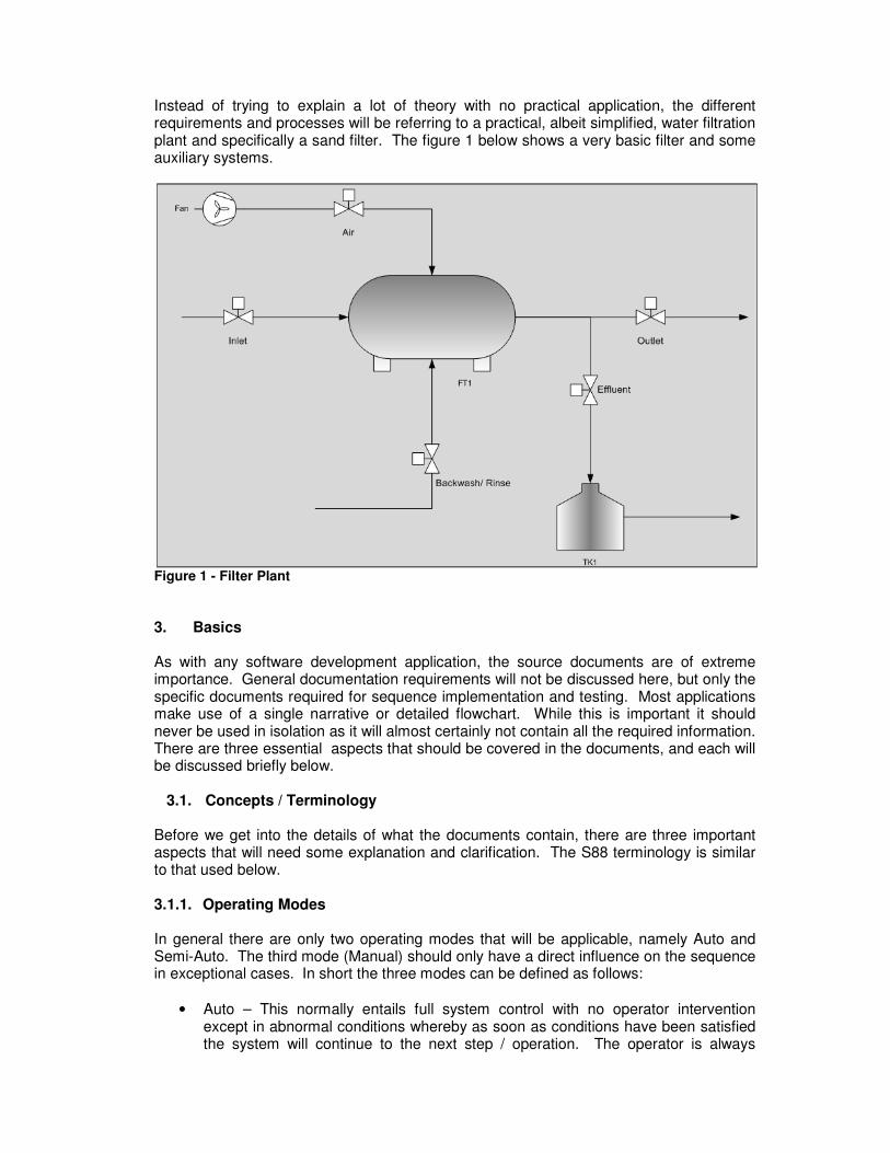
Instead of trying to explain a lot of theory with no practical application, the different requirements and processes will be referring to a practical, albeit simplified, water filtration plant and specifically a sand filter. The figure 1 below shows a very basic filter and some auxiliary systems.
Figure 1 - Filter Plant
3. Basics As with any software development application, the source documents are of extreme importance. General documentation requirements will not be discussed here, but only the specific documents required for sequence implementation and testing. Most applications make use of a single narrative or detailed flowchart. While this is important it should never be used in isolation as it will almost certainly not contain all the required information. There are three essential aspects that should be covered in the documents, and each will be discussed briefly below.
3.1. Concepts / Terminology Before we get into the details of what the documents contain, there are three important aspects that will need some explanation and clarification. The S88 terminology is similar to that used below. 3.1.1. Operating Modes In general there are only two operating modes that will be applicable, namely Auto and Semi-Auto. The third mode (Manual) should only have a direct influence on the sequence in exceptional cases. In short the three modes can be defined as follows:
• Auto – This normally entails full system control with no operator intervention except in abnormal conditions whereby as soon as conditions have been satisfied the system will continue to the next step / operation. The operator is always
informed of where in the process the sequence currently resides, with normally no operator intervention.
• Semi-Auto – This is where operator action is required, even though all other requirements are met to continue to the next step / operation. This is normally used when the plant is in a state where it can remain almost indefinitely. Operator actions can take various shapes, from physical actions like swinging manual valves in the field to a simple graphical confirmation to continue. This mode of operation is very useful in batch control, but it needs to be planned and laid out carefully.
• Manual – This is where the operator takes full control of the plant and bypasses the sequence. This should be avoided as far as possible as there is the possibility of leaving the process in an unsafe state. There are cases when it is sometimes unavoidable and this mode should be used.
3.1.2. Sequence Modes It is important that sequence modes not be confused with operational modes even though most systems make provision for operating sequences in auto, semi-auto and manual, sequence modes denote specifically different states of the sequence. Generally these modes will be available for use when the sequence is in Auto and Semi-Auto. The critical modes defined below are Running, Hold, Interrupt and Abort. Different systems use different terms, but those of you familiar with the Allen Bradley and Honeywell systems will recognise these terminologies.
• Running is the normal state of the sequence when the plant is operating as it should and no problems are present.
• Hold is the most likely mode to be used when an abnormal condition occurs. In a hold state the sequence is paused, including things like timers, the operator is alerted that something is wrong and the sequence waits until either the conditions are normal or an abort occurs. When conditions return to normal the sequence will continue where it was last paused.
• Interrupt generally takes the second highest priority. It is not always used due to the complexity involved in returning the plant from an interrupt. The interrupt is normally used where some common piece of equipment malfunctions and all the sequences and systems dependant on the equipment needs to be put in a safe state until the problem is rectified. While it may sound similar to the hold, the difference is that the plant is made safe and after the problem has been rectified will be returned to where it was when the problem occurred. When deciding to use this mode it is crucial that the relevant process engineers be involved to ensure that both the shutdown and the return to service are done correctly to ensure continued operation.
• Abort is the highest priority and it is crucial that the option to abort always be available to the operator. A command to abort will override all other states and commands. This is normally used as an emergency shutdown. This can also be used even should the sequence be in hold or interrupt. The abort command can be issued either by manual operator action or by a specific process condition.
3.1.3. Operations and Steps The terminology used in S88 is slightly different, but it is crucial to understand the concepts regardless of what terminology is used.
Operations can be described as a high level action to be performed and can contain anything from a single step to ten or more steps. Let us look at Figure 2 below for an example.
Figure 2 - Tank Fill
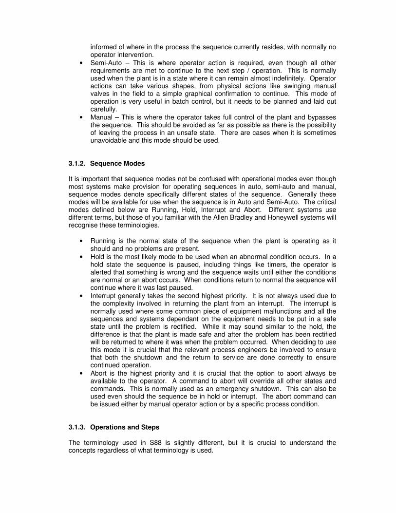
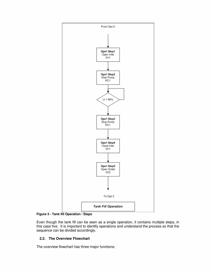
Assume for a moment that the tank needs to be filled with a batch chemical required by the downstream process. The tank fill will be a single operation comprising various steps. In this case the detailed operation could look like this: Start with the level being lower than a predetermined value.
Figure 3 - Tank fill Operation / Steps
Even though the tank fill can be seen as a single operation, it contains multiple steps, in this case five. It is important to identify operations and understand the process so that the sequence can be divided accordingly.
3.2. The Overview Flowchart The overview flowchart has three major functions:
1. Giving an overview of the process and sequence including alternative paths for the sequence to follow. It also shows where operator alerts and progress messages will be issued.
2. Identifying sequence actions in case of abnormal conditions. 3. Identification of operating modes for the different operations.
The flowchart is high level and identifies operations only. Normally the detail flowchart will only give the default path of flow; that is why the overview flowchart is so important. Base on the plant as shown in figure 1 above, the overview flowchart could look like this:
Figure 4 - Plant Overview Flowchart
The flowchart is also useful for providing the maintenance and operating personnel with a quick reference of where in the overall sequence the program currently is, thus providing for easier fault finding. Process interlocks can also be defined here. If for instance the Backwash and Rinse operations need to be suspended when a high level occurs in the effluent tank, it could be indicated on this flowchart.
3.3. The Detail Flowchart This is the document most widely used and it can also take the form of a narrative. There are some aspects that need to be included in the flowchart for it to be considered complete.
1. Operational references must be included. 2. A short description of what happens in each step need to be provided. 3. Discrete actions need to be shown. 4. Requirements for step completion need to be defined.
The detail flowchart need to show all operations and associated steps, but does not normally indicate alternative sequence paths. Typically as a minimum the devices operated in each step will be checked, but all devices required for sequence operation may also be checked. Common equipment, like the fan, will only be checked in the operation in which it is used. Figure 5 below shows the detailed flowchart for operation 4 “Air Scouring”.
Figure 5 - Air Scouring Detail Flowchart
As can be seen in this case all the relevant equipment states are checked. It is not necessary that the flowchart be presented in this format, provided that it is consistent and give the relevant information. It should also be noted that the abnormal condition actions are not specified in this example, although it can be specified if required.
3.4. The Sequence Matrix This is the document least likely to be used, but conversely is one of the most useful documents for the developer. The matrix is closely linked to the sequence modes and specifically the Hold and Abort modes. It is also very useful when creating a sequence display indicating to the operator what the current active step is and what the equipment states should be. Again, it can take various forms, but the most common one is that of a table display. Referring to the “Air scouring” operation the matrix should look similar to this figure 6 below:
LEGEND:
C: CLOSE
O: OPEN
STR: START
CMP: COMPLETE
R: RUNNING
STP: STOP
Actions Soft Actions Step Completion
Air
Inle
t
Ou
tle
t
Ba
ckw
ash
/Rin
se
Eff
lue
nt
Ou
tle
t
Fa
n
Sco
uri
ng
Tim
er
Ba
ckw
ash
Tim
er
Rin
se T
ime
r
Air
Inle
t
Ou
tle
t
Ba
ckw
ash
/Rin
se
Eff
lue
nt
Ou
tle
t
Fa
n
Sco
uri
ng
Tim
er
Ba
ckw
ash
Tim
er
Rin
se T
ime
r
Operation Step Description
4 1 FILTER ISOLATION C C C C C C C C C C C C STP
4 2 AIR SCOUR PREP O O O C C C O C STP
4 3 FAN START STR O C C C O C STR
4 4 SCOURING STR O C C C O C STR CMP
4 5 SCOURING COMPLETE C STP C C C C O C STP
Figure 6 - Air Scouring Sequence Matrix
An additional section can be added for process actions and conditions like the setting of flow set points. In all other operations the fan state will be ignored. 4. Putting it together Now that we know what the requirements are, how do we put it all together? For the sake of this discussion we will be concentrating on the following three sequence states:
• Running
• Hold
• Abort For the sake of continuity I will again use the example of the “Air Scouring” operation; the other operations will follow the same pattern. The abort will be independent of any operation as it will need to be accessible anytime.
4.1. Running Due to the size of the sequence required, we will only be looking at steps 3 and 4 of the air scouring operation. It is left to the reader to construct the other steps if required. In the case of this sequence we monitor all the relevant equipment. All the transitions between steps need to reflect this requirement. Due to the vast variety of sequence formats used in industry I will be using a generic flowchart type depiction. As will be seen the actual software indicate some requirements that are not specified in the source documents, this will be system dependant and is only shown as a possible option that the developer might need to put in. The step and transition numbering was chosen for easy reference to the source documents, again it will be dependent on customer requirements and the system used. Figure 7 below shows what the software should look like for the two steps.
Figure 7 - Example for Running Software
Transitions are indicated in light blue and the steps in white. In addition to the actions and checks required by the process the software also checks whether the devices that will be operated in the next step are actually ready to be operated. This just prevents unnecessary failures in the sequence. In addition the system will also set an indication, this can be a flag or a bit, to indicate in which specific step the sequence is currently busy. While it is useful for operator indications, it is critical for the correct operation of the hold mode.
4.2. Hold Here the sequence matrix comes into its own as it makes it very easy to trace any possible problems and program the hold mode. Depending on the system being used, the hold can be included as part of the main sequence or it can be separated into another hold handler. Irrespective of how the system operates the general layout of the hold mode should be the same. The hold for the whole of operation 4 “Air Scouring is indicated below.
Figure 8 - Operation 4 Hold
The hold can also perform limited actions if it is required to operate certain field devices. Should the fault require a shutdown, it should be included in the Abort conditions. If the operator is required to set the devices to the correct state it must be ensured that he is given access to operate the devices. The hold has the following functions:
• Provide operator information on current sequence state, plant state and failure.
• Provide the required operator access to relevant field equipment.
• Execute limited actions, serious failures requiring plant shutdown should execute the abort.
• Automatically provide a return to the point of last execution when the failure has been resolved.
The hold can be seen as a first level intervention and should be used only when the failure or abnormal condition has a limited impact and does not result in possible safety concerns or plant damage. Should immediate operator action be required the failure should either be handled through an interrupt or an abort.
The hold can be incorporated as part of the main sequence in an alternative branch for steps where it is required. This simplifies the return to normal condition, but can make the sequence difficult to read and follow. The developer and the customer should decide on the required format before development starts.
4.3. Abort As mentioned earlier the abort function has the highest priority and should always be available to the operator. Typically the abort will initialise the sequence to a specific start point, normally the shutdown operation. The main (Running) sequence should always start at the same point to allow correct operation. Since the abort is normally used in emergencies or in case of major failure, the device readiness for operation is not checked. Provision can however be made for controlled shutdowns if required to prevent process upsets. For the sake of simplicity we will only use the fan as an example of such a controlled shutdown scenario.
Figure 9 - Abort
The abort can be initiated by any trip condition, but partial trips should be catered for either in the hold or interrupt modes, depending on complexity. Any emergency condition that requires an automatic process shutdown should be included as part of the conditions that can initiate an abort. Where separate safety
shutdown systems is being utilised, provision must be made for system co-ordination that would allow the sequence and process shutdowns to be done together. 5. Conclusion At first glance the process described above might seem overly complex. While it is certainly true that not all sequences need this kind of structured robustness, it does have a very wide area of application. Following this standard makes it easier for developers and customers to standardise and test systems. Maintenance and to a lesser extent production personnel also find it easier to fault find and correctly react to abnormal conditions. The reader should be aware that pre-work, especially on the documentation availability upfront, determines the success of the sequence configuration. Should there be any questions about the application described here; the reader is welcome to contact the author for more information.