Topsfield Engineering Service, Inc. Figure 1 Thermoelastic Analysis in Design William Bell & Paul-W. Young Topsfield Engineering Service, Inc. John Stewart, Saber Design and Analysis Services, LLC.
Transcript
Topsfield Engineering Service, Inc. Figure 1
Thermoelastic Analysis in Design
William Bell & Paul-W. YoungTopsfield Engineering Service, Inc.
John Stewart, Saber Design and Analysis Services, LLC.
Topsfield Engineering Service, Inc.
Slide 2
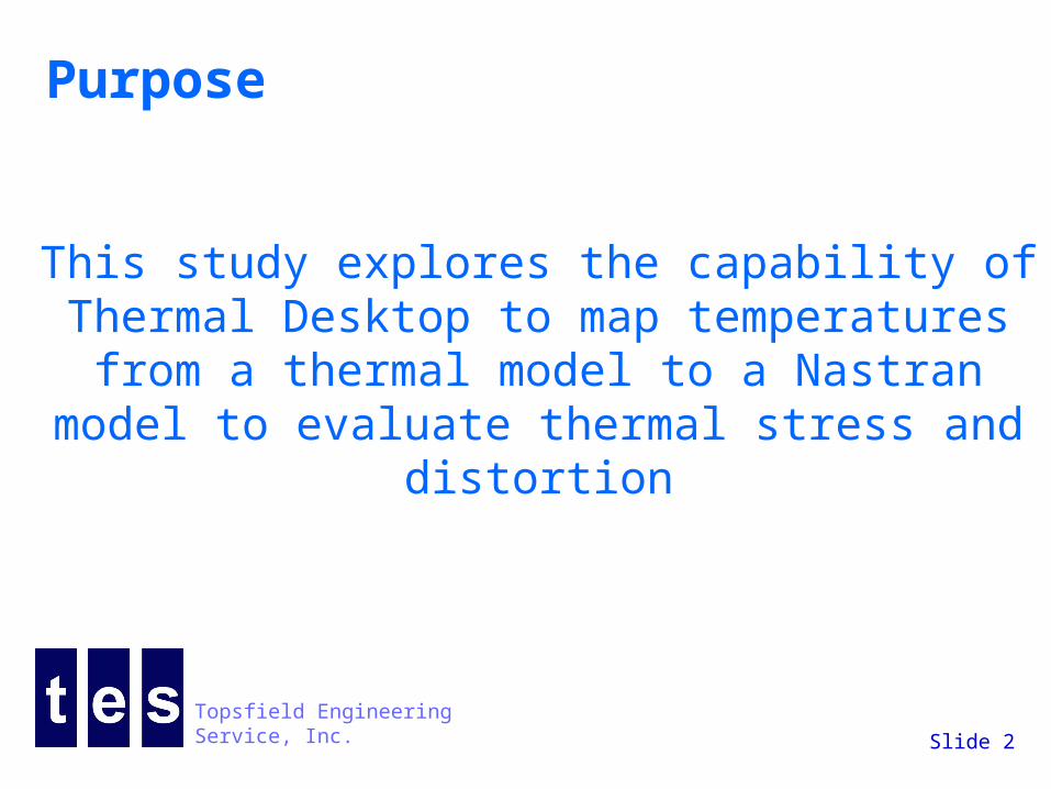
Purpose
This study explores the capability of Thermal Desktop to map temperatures
from a thermal model to a Nastran model to evaluate thermal stress and distortion
Topsfield Engineering Service, Inc.
Slide 3
Applications Rapid cool-down to cryogenic temperatures Differential thermal expansion causing
leakage, failure, galling, or seizing Electronics components Misalignment due to thermal distortion Time dependent and steady state conditions Space optics - optical alignment Gasket/seal seating - pressure containing Thermal contact joint design
Topsfield Engineering Service, Inc.
Slide 4
Tools Used
Thermal Desktop from C & R Technologies – Version 4.7 patch 16
FEMAP V8.3 and NX NASTRAN V2.0
Topsfield Engineering Service, Inc.
Slide 5
Study Assembly½” thick heated plate with a serpentine pipe 1/8” sch 40 pipe attached to the plate for temperature control
Heat Loads
20 watts/in2
15 watts/in2
Topsfield Engineering Service, Inc.
Slide 6
Thermal Model Development
Evolved from a early version of a Thermal Desktop model
Rebuilt using latest modeling objects without simplifying dimensions
Picked off dimensions from the Autocad drawing for creation of the Nastran model
Result - there were some discrepancies
Topsfield Engineering Service, Inc.
Slide 7
Thermal Study Conditions
Mass Flow cooling - Coolant – 100 lb/hr of Nitrogen gas at -200 F and 40 psig – built-in properties for Nitrogen
No Radiation Heat Transfer Plate is heated with 1150 watts Conduction within plate and pipe walls Built in convection equations for heat transfer from
pipe to Nitrogen Steady State Conditions (although Thermal Desktop
can solve time dependent cases and search for worst case conditions)
Topsfield Engineering Service, Inc.
Slide 8
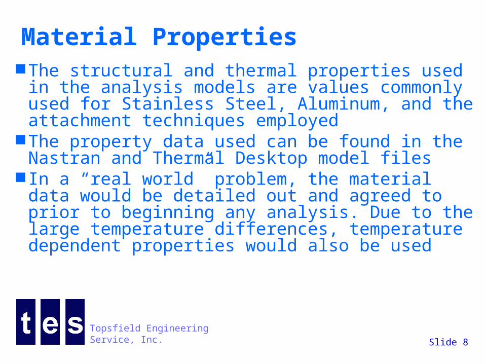
Material Properties The structural and thermal properties used in
the analysis models are values commonly used for Stainless Steel, Aluminum, and the attachment techniques employed
The property data used can be found in the Nastran and Thermal Desktop model files
In a “real world” problem, the material data would be detailed out and agreed to prior to beginning any analysis. Due to the large temperature differences, temperature dependent properties would also be used
Topsfield Engineering Service, Inc.
Slide 9
Thermal Desktop Model Construction
Pipe with wall (1/8” nps - sch 40) built on a polyline
Lumps and paths within pipe
Ties representing the convective heat transfer from the pipe wall to the fluid lumps
Three brick objects with edge nodes merged for the plate except for Case D where the plate was created from the Nastran grooved plate. Plate is ½” thick
Heat flux applied to the bottom surface of two of the bricks
Contactor object to represent the pipe to plate bond. In the groove the bond thickness is 0.003”. The weld to the flat plate is an 1/8” fillet
Topsfield Engineering Service, Inc.
Slide 10
Cases evaluated in Nastran
A - Pipe bonded to grooved plate – Nastran pipe and plate from chexa elements
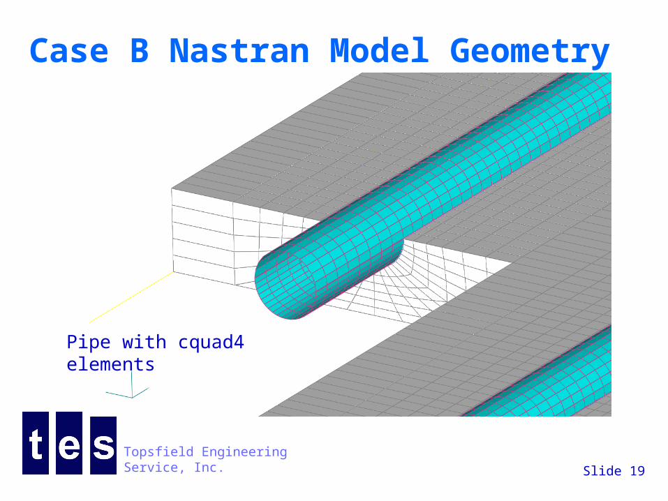
B - Pipe bonded to grooved plate – Nastran pipe from cquad4 elements and plate from chexa elements
C - Pipe welded to flat plate – Nastran pipe from cquad4 elements and plate from chexa elements
D - Pipe bonded to grooved plate – Nastran pipe and plate from chexa elements – TD plate from the Nastran plate
Topsfield Engineering Service, Inc.
Slide 11
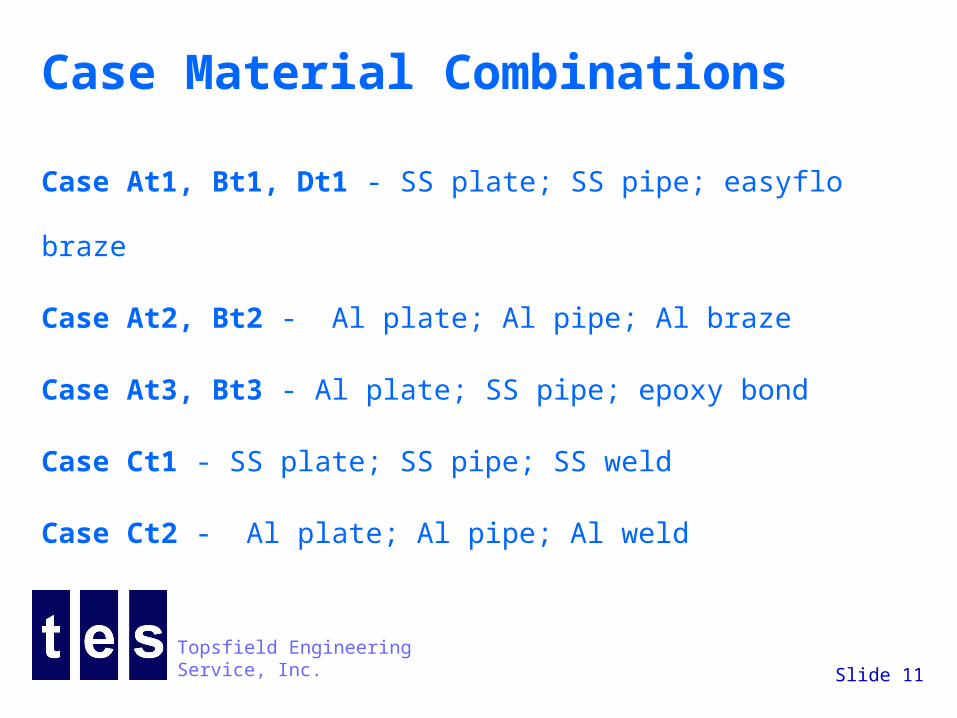
Case Material Combinations
Case At1, Bt1, Dt1 - SS plate; SS pipe; easyflo braze
Case At2, Bt2 - Al plate; Al pipe; Al braze
Case At3, Bt3 - Al plate; SS pipe; epoxy bond
Case Ct1 - SS plate; SS pipe; SS weld
Case Ct2 - Al plate; Al pipe; Al weld
Topsfield Engineering Service, Inc.
Slide 12
Cases A and B
Pipe bonded to a groove in the plate.
Case B – pipe from cquad4 elements and plate from chexa elements
Case A – pipe and plate from chexa elements
Topsfield Engineering Service, Inc.
Slide 13
Case C
Pipe with cquad4 elements attached with chexa solid elements to the top surface of the solid plate of chexa solid elements.
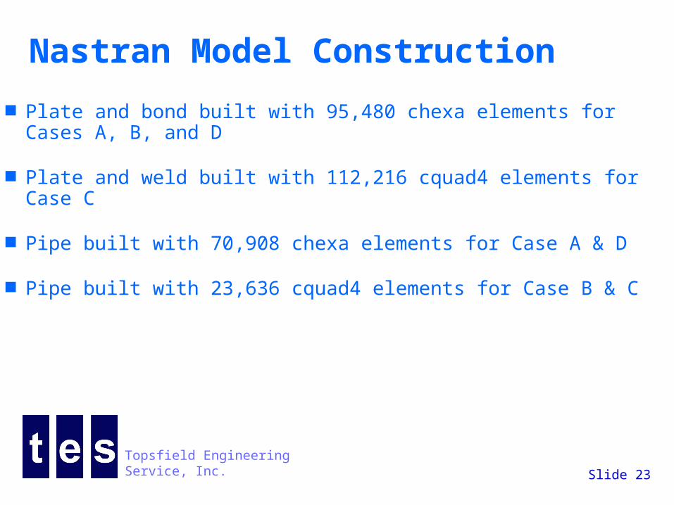
Plate and bond built with 95,480 chexa elements for Cases A, B, and D
Plate and weld built with 112,216 cquad4 elements for Case C
Pipe built with 70,908 chexa elements for Case A & D
Pipe built with 23,636 cquad4 elements for Case B & C
Topsfield Engineering Service, Inc.
Slide 24
Temperature Mapping Procedure
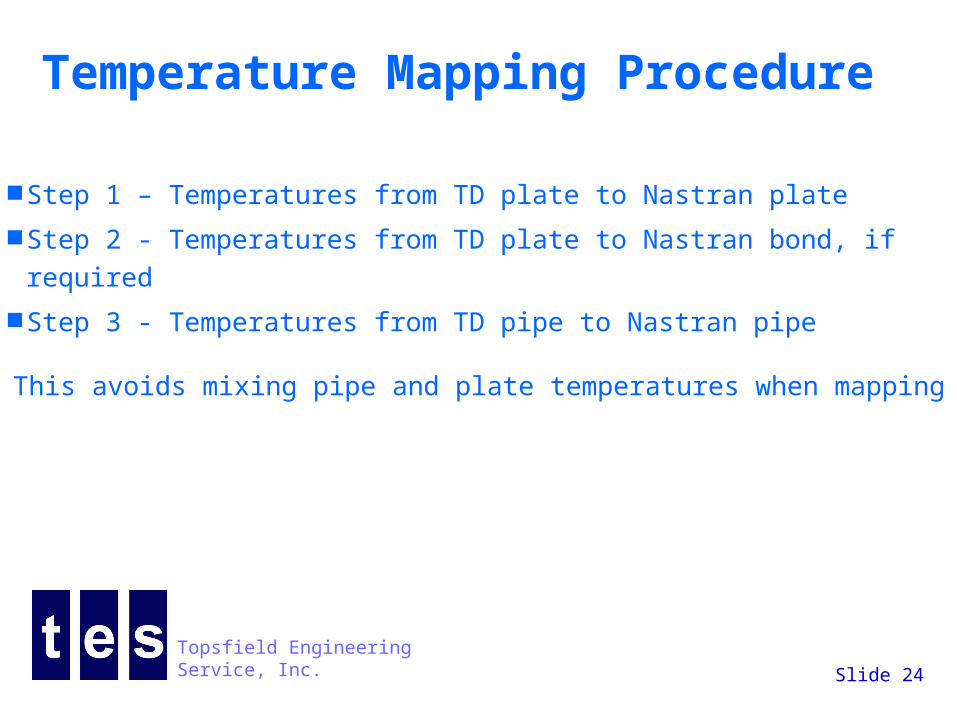
Step 1 – Temperatures from TD plate to Nastran plate
Step 2 - Temperatures from TD plate to Nastran bond, if required
Step 3 - Temperatures from TD pipe to Nastran pipe
This avoids mixing pipe and plate temperatures when mapping
Topsfield Engineering Service, Inc.
Slide 25
Mapping tolerances
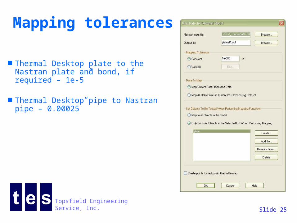
Thermal Desktop plate to the Nastran plate and bond, if required – 1e-5”
Thermal Desktop pipe to Nastran pipe – 0.00025”
Topsfield Engineering Service, Inc.
Slide 26
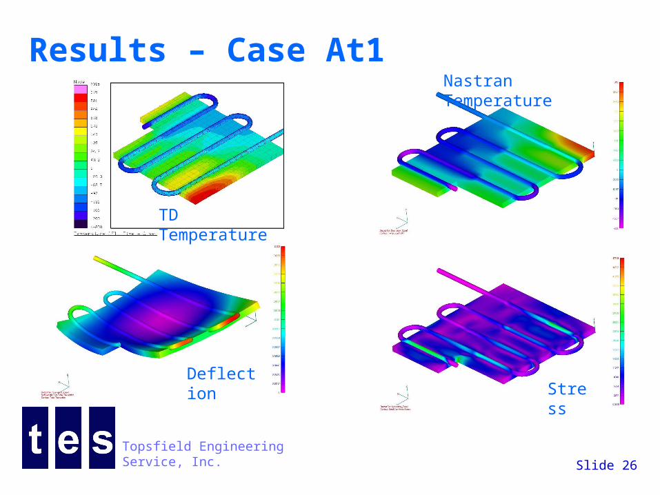
Results – Case At1
TD Temperature
Nastran Temperature
Deflection Stres
s
Topsfield Engineering Service, Inc.
Slide 27
Results – Case Bt1
TD Temperature
Nastran Temperature
Deflection
Stress
Topsfield Engineering Service, Inc.
Slide 28
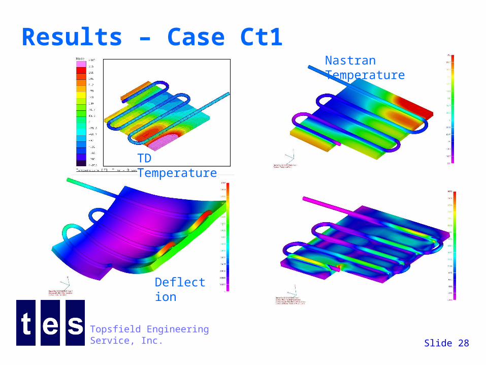
Results – Case Ct1
TD Temperature
Nastran Temperature
Deflection
Stress
Topsfield Engineering Service, Inc.
Slide 29
Results – Case Dt1
TD Temperature
Nastran Temperature
Deflection
Stress
Topsfield Engineering Service, Inc.
Slide 30
Results – Case At1 versus Dt1
Dt1 Stress
Dt1 Stress
At1 Stress
At1 Stress
Topsfield Engineering Service, Inc.
Slide 31
Results – Case At2
TD Temperature
Nastran Temperature
Deflection Stres
s
Topsfield Engineering Service, Inc.
Slide 32
Results – Case Bt2Nastran Temperature
Deflection
Stress
TD Temperature
Topsfield Engineering Service, Inc.
Slide 33
Results – Case Ct2
TD Temperature
Nastran Temperature
Deflection Stres
s
Topsfield Engineering Service, Inc.
Slide 34
Results – Case At3
TD Temperature
Nastran Temperature
Deflection
Stress
Topsfield Engineering Service, Inc.
Slide 35
Results – Case Bt3
TD Temperature
Nastran Temperature
Deflection
Stress
Topsfield Engineering Service, Inc.
Slide 36
Case At1 Thermal Results
Cross section for temperature and Nastran Results
Thermal model node numbers
Topsfield Engineering Service, Inc.
Slide 37
Case At1 Thermal ResultsTemperatures in TD plate
Temperatures in TD pipe
Topsfield Engineering Service, Inc.
Slide 38
Case Dt1 Thermal ResultsTemperatures in TD plate from Nastran model
Temperatures in TD pipe
Topsfield Engineering Service, Inc.
Slide 39
Case At1 Thermal Results
Temperatures in Nastran plate from TD model
Topsfield Engineering Service, Inc.
Slide 40
Nastran Results Summary
CasesMaximum Von Mises
Stress at Cross Section psi
Maximum Deflection -
inches
Maximum Temperature -
F
Case At1 47,149 0.02200 314
Case At2 5,532 0.00811 30
Case At3 30,574 0.03900 67
Case Bt1 39,968 0.02300 314
Case Bt2 11,879 0.01130 30
Case Bt3 24,110 0.01290 67
Case Ct1 36,762 0.04200 451
Case Ct2 17,648 0.01230 55
Case Dt1 88,310 0.02660 418
Topsfield Engineering Service, Inc.
Slide 41
Lessons Learned - thermal Spend some time reviewing thermal results:
Determining if nodalization is sufficient – distortion or stress
Choosing materials and material thermal properties Assuring convergence Getting separate files for each component of the model
and putting each component on a separate layer Plan out the combinations with the design team Carefully check to see if the temperature mapping
is accurate Let go of the fear of finite elements
Topsfield Engineering Service, Inc.
Slide 42
Lessons learned - structural Spend some time working with the thermal analyst:
Getting dimensions consistent Sorting out materials and structural properties up front Determining the mounting constraint Getting separate files for each component of the model
Plan out the combinations with the design team Carefully check to see if the temperature mapping
is accurate Do hand calculations as a check on stresses and
deflections
Topsfield Engineering Service, Inc.
Slide 43
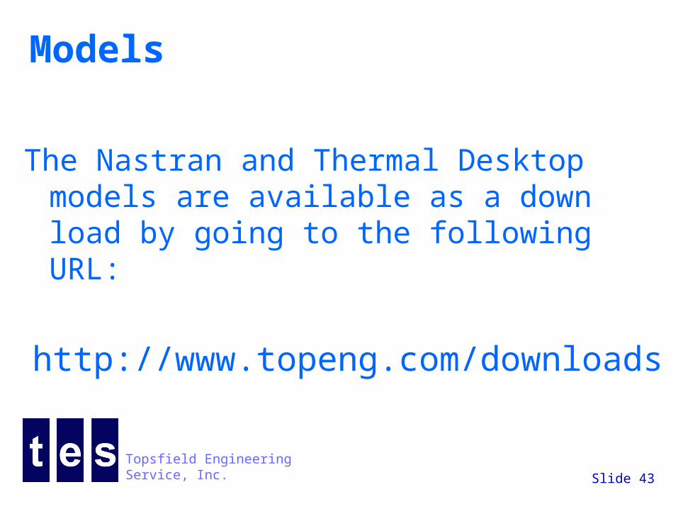
Models
The Nastran and Thermal Desktop models are available as a down load by going to the following URL: