Data sheet DS/TORBAR-EN Rev. E Torbar Averaging pitot tubes Economical flow metering solutions for gases, liquids and steam Unique profile shape — Offers high flow turndown No drift in co-efficient — Ensures long term stability One-piece outer tube — For pipes up to 5000 mm (197 in.) diameter — Ensures optimum strength Low permanent pressure loss — Means low energy consumption & cost — Reduced carbon footprint Suitable for wide range of pipe sizes — For circular, square or rectangular section ducts of 10 to 8000 mm (0.4 to 315 in.) diameter Dual averaging — For improved accuracy with asymmetric flow profiles Hot-tap versions available — Allows insertion into pressurized pipes Optional Integral Transmitter — For volumetric or mass flow metering
Transcript
Data sheet DS/TORBAR-EN Rev. E
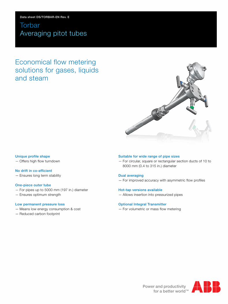
TorbarAveraging pitot tubes
Economical flow metering solutions for gases, liquids and steam
Unique profile shape — Offers high flow turndown
No drift in co-efficient — Ensures long term stability
One-piece outer tube — For pipes up to 5000 mm (197 in.) diameter— Ensures optimum strength
Low permanent pressure loss — Means low energy consumption & cost— Reduced carbon footprint
Suitable for wide range of pipe sizes — For circular, square or rectangular section ducts of 10 to
8000 mm (0.4 to 315 in.) diameter
Dual averaging — For improved accuracy with asymmetric flow profiles
Hot-tap versions available — Allows insertion into pressurized pipes
Optional Integral Transmitter— For volumetric or mass flow metering
TorbarAveraging pitot tubes
2 DS/TORBAR–EN Rev. E
TORBARThe TORBAR is a multiport self-averaging flow meter with adesign based on the classical pitot tube concept of fluid flowmeasurement and with thousands having been installed into alarge variety of industries world wide.
The TORBAR produces an averaged differential pressure (DP)signal proportional to the square of the flow rate.
The DP output is normally piped to a Differential Pressuretransmitter in order to generate an electrical signal proportionalto the flow rate. For certain applications, the DP transmitter canbe directly mounted on to the TORBAR via an integral valvemanifold.
Each TORBAR is designed to span the process pipe diameterand comprises four basic components:
Outer impact tube – ONE PIECE CONSTRUCTION 1
Internal averaging tube 2
Low pressure chamber
Head with HP and LP impulse connections
The outer impact tube has a number of pressure sensing holesfacing upstream which are positioned at equal annular points inaccordance with a log-linear distribution. The 'total pressures'developed at each upstream hole by sum of the impact of theflowing medium and the static pressure are firstly averagedwithin the outer impact tube and then to a second order (andmore accurately) averaged within the internal averaging tube.This pressure is represented at the head as the high pressurecomponent of the DP output. The low pressure component isgenerated from a single sensing hole located on thedownstream side of the outer impact tube, measuring staticpressure. For bi-directional flow measurement, the TORBAR canbe supplied with the same number of downstream ports asupstream.
The TORBAR is an improvement on the round sensor designdue to the unique profiled flats which are positioned around thedownstream hole in order to define the separation point at whichthe flow lines separate as the fluid passes around the outerimpact tube. This feature creates a stable pressure area at thedownstream pressure sensing hole thereby maintaining a moreconstant flow coefficient at high velocities enabling a very widerange of flow measurement (turndown).1 due to manufacturing constraints, units longer than 5 metreswill have 2-piece construction.2 due to manufacturing constraints, not available for models121, 122, 123, 301, 311 or for any units coded to include theoptions NRTB or NRTT.
Permanently Installed Types
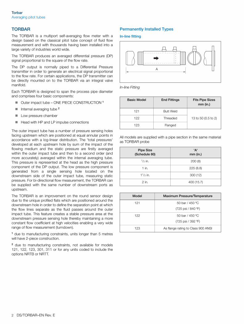
In-line fitting
All models are supplied with a pipe section in the same materialas TORBAR probe
In-line Fitting
Basic Model End Fittings Fits Pipe Sizes mm (in.)
121 Butt Weld
122 Threaded 13 to 50 (0.5 to 2)
123 Flanged
Pipe Size(Schedule 80)
'A'mm (in.)
1/2 in. 200 (8)
1 in. 225 (8.8)
11/2 in. 300 (12)
2 in. 400 (15.7)
Model Maximum Pressure/Temperature
121 50 bar / 450 ºC
(725 psi / 840 ºF)
122 50 bar / 450 ºC
(725 psi / 392 ºF)
123 As flange rating to Class 900 ANSI
A
TorbarAveraging pitot tubes
DS/TORBAR–EN Rev. E 3
Threaded Fitting
All Models are supplied with carbon steel pipe weld fitting andstainless steel compression gland as standard. (Other materialsavailable)
Flanged Fitting – Standard
Models 301, 401 and 402
Basic Model D mm (in.) Fits Pipe Sizes mm (in.)
301 13 (0.5) 50 to 150 (2 to 6)
401** 25 (1) 100 to 1800 (4 to 70)
402* 25 (1) 100 to 5000 (4 to 200)
** For liquid flow applications where there is a possibility of process pulsations or intermittent excessive flow velocity, the end-support model should always be selected for pipe sizes over 250 mm (10 in.) internal diameter.
* With end support
Maximum Pressure / Temperature
Model 301
Model 401, 402
50 Bar @ 400 °C (725 psi @ 752 ºF)
50 Bar @ 400 °C (725 psi @ 752 ºF)
All Models are supplied with carbon steel pipe weld fitting and stainless steel compression gland as standard (other materials available).
Compression Gland
Weld Fitting
End Support with Threaded Plug (402 Only)
D
Models 311, 411 and 412
Basic Model D mm (in.) Fits Pipe Sizes mm (in.)
311 13 (0.5) 50 to 150 (2 to 6)
411** 25 (1) 100 to 1800 (4 to 70)
412* 25 (1) 100 to 5000 (4 to 200)
** For liquid flow applications where there is a possibility of process pulsations or intermittent excessive flow velocity, the end-support model should always be selected for pipe sizes over 250 mm (10 in.) internal diameter.
* With end support
Standard Flange Size
Model 311 1 in. (DN 25)
Model 411 11/2 in. (DN 40)
(Other sizes available)
Maximum Pressure / Temperature
All models as flange rating to class 1500 ANSI. For higher pressures / temperature consult factory.
All Models are supplied without flanged pipe fitting or stud bolts and gaskets as standard. These are available as accessories.
Weld Cup End Support (412 Only)
D
TorbarAveraging pitot tubes
4 DS/TORBAR–EN Rev. E
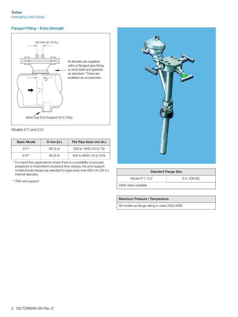
Flanged Fitting – Extra Strength
Models 511 and 512
Basic Model D mm (in.) Fits Pipe Sizes mm (in.)
511* 60 (2.4) 250 to 1800 (10 to 70)
512** 60 (2.4) 400 to 8000 (16 to 315)
* For liquid flow applications where there is a possibility of process pulsations or intermittent excessive flow velocity, the end-support model should always be selected for pipe sizes over 600 mm (24 in.) internal diameter.
** With end support
54 mm (2.12 in.)
All Models are supplied without flanged pipe fitting or stud bolts and gaskets as standard. These are available as accessories.
Weld Cup End Support (512 Only)
D
Standard Flange Size
Model 511, 512 3 in. (DN 80)
Other sizes available
Maximum Pressure / Temperature
All models as flange rating to class 2500 ANSI.
TorbarAveraging pitot tubes
DS/TORBAR–EN Rev. E 5
Options
Probe Material Code
316 Stainless Steel SS
304L Stainless Steel 4S
Monel 400 ML
Hastelloy C HC
6MO 6M
Duplex DX
Super Duplex SDX
Other Specify
Probe Material Code
Male without valves Female without valves Flanged without valves
Code example:
007M (1/2 in. NPT)
Code example:
006F (12 mm [1/2 in.] weld socket)
Code example:
009(12 mm[1/2 in.])specify pressure class
With needle valves With ball vales With gate valves
Code example:
SV4(st. steel1/4 in. BSPT)
Code example:
BB3(brass1/4 in.NPT)
Code example:
CG8(carbon steel1/2 in BSPT)
Direct mount head Direct mount separate manifold Direct mount integral manifold
Code: 000
Specify accessory: 0VDM
Code: 000
Specify accessory:3VDM(3 valve)5VDM(5 valve)
Code: 000
Specify accessory: DM3V Bolting =4 x M10 x 30 mm(others available)
DP Output Connections/Valves
TorbarAveraging pitot tubes
6 DS/TORBAR–EN Rev. E
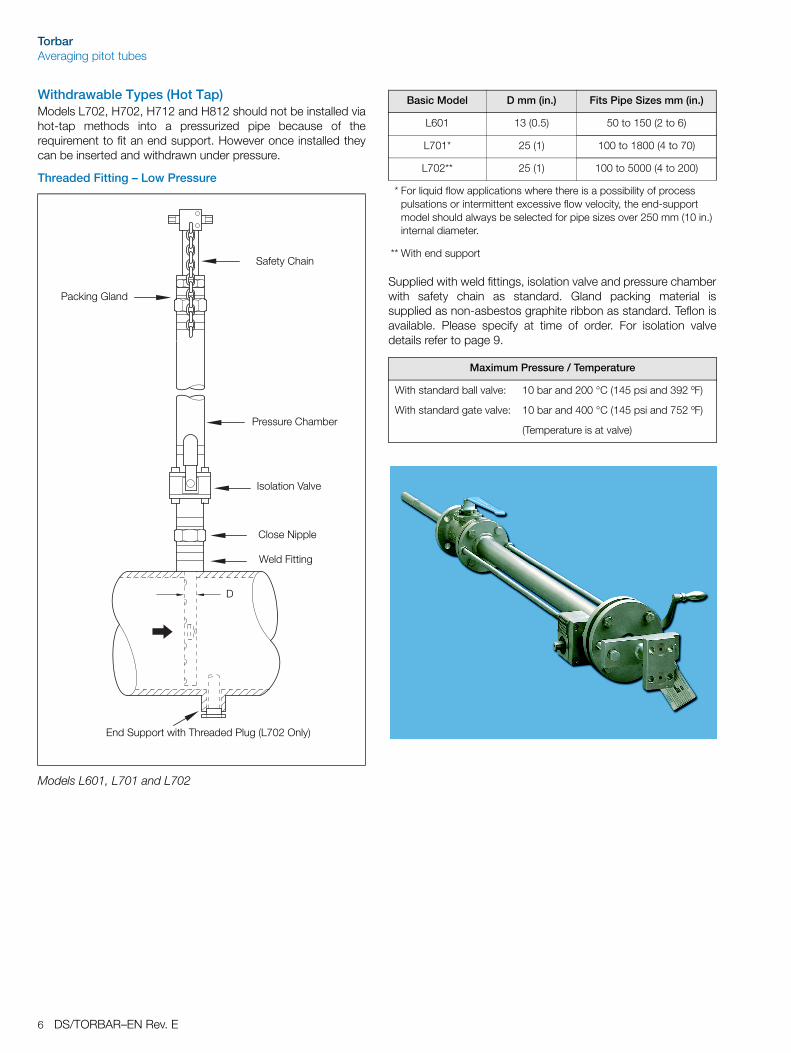
Withdrawable Types (Hot Tap)Models L702, H702, H712 and H812 should not be installed viahot-tap methods into a pressurized pipe because of therequirement to fit an end support. However once installed theycan be inserted and withdrawn under pressure.
Threaded Fitting – Low Pressure
Supplied with weld fittings, isolation valve and pressure chamberwith safety chain as standard. Gland packing material issupplied as non-asbestos graphite ribbon as standard. Teflon isavailable. Please specify at time of order. For isolation valvedetails refer to page 9.
Models L601, L701 and L702
End Support with Threaded Plug (L702 Only)
Weld Fitting
Close Nipple
Isolation Valve
Pressure Chamber
Safety Chain
Packing Gland
D
Basic Model D mm (in.) Fits Pipe Sizes mm (in.)
L601 13 (0.5) 50 to 150 (2 to 6)
L701* 25 (1) 100 to 1800 (4 to 70)
L702** 25 (1) 100 to 5000 (4 to 200)
* For liquid flow applications where there is a possibility of process pulsations or intermittent excessive flow velocity, the end-support model should always be selected for pipe sizes over 250 mm (10 in.) internal diameter.
** With end support
Maximum Pressure / Temperature
With standard ball valve: 10 bar and 200 °C (145 psi and 392 ºF)
With standard gate valve: 10 bar and 400 °C (145 psi and 752 ºF)
(Temperature is at valve)
TorbarAveraging pitot tubes
DS/TORBAR–EN Rev. E 7
Threaded Fitting – High Pressure
Supplied with weld fittings, isolation valve, pressure chamberand draw bolt retraction (illustrated) as standard. Gland packingmaterial is supplied as non-asbestos graphite ribbon asstandard. Teflon is available (specify at time of order). Gearedretraction — Optional. For isolation valve details refer to page 9.
Model H701 and H702
Drawbolt Retraction
Pressure Chamber
Isolation Valve
PackingGland
Close Nipple
Weld Fitting
End Support with Threaded Plug (H702 Only)
D
Basic Model D mm (in.) Fits Pipe Sizes mm (in.)
L601 13 (0.5) 50 to 150 (2 to 6)
H701* 25 (1) 100 to 1800 (4 to 70)
H702** 25 (1) 100 to 5000 (4 to 200)
* For liquid flow applications where there is a possibility of process pulsations or intermittent excessive flow velocity, the end-support model should always be selected for pipe sizes over 250 mm (10 in.) internal diameter.
** With end support
Maximum Pressure / Temperature
With standard ball valve: 40 bar and 200 °C (580 psi and 392 ºF)
With standard gate valve: 40 bar and 400 °C (580 psi and 752 ºF)
(Temperature is at valve)
TorbarAveraging pitot tubes
8 DS/TORBAR–EN Rev. E
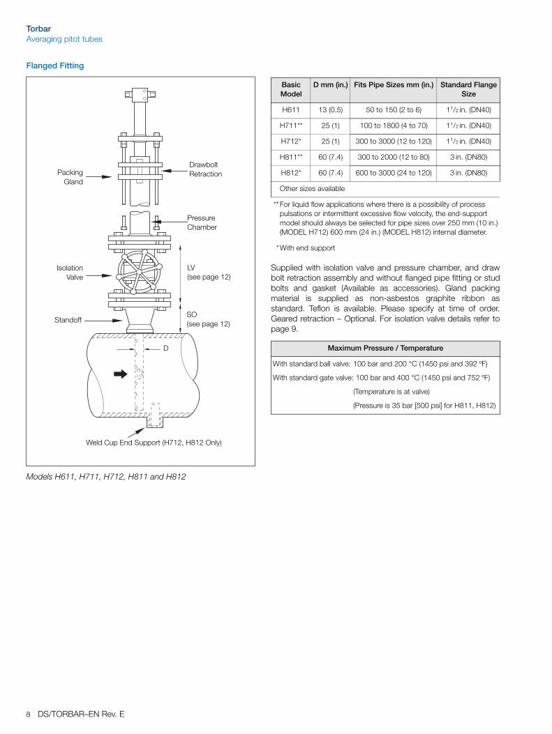
Flanged Fitting
Supplied with isolation valve and pressure chamber, and drawbolt retraction assembly and without flanged pipe fitting or studbolts and gasket (Available as accessories). Gland packingmaterial is supplied as non-asbestos graphite ribbon asstandard. Teflon is available. Please specify at time of order.Geared retraction – Optional. For isolation valve details refer topage 9.
Models H611, H711, H712, H811 and H812
Drawbolt Retraction
Pressure Chamber
IsolationValve
PackingGland
Standoff
LV (see page 12)
Weld Cup End Support (H712, H812 Only)
SO (see page 12)
D
Basic Model
D mm (in.) Fits Pipe Sizes mm (in.) Standard Flange Size
H611 13 (0.5) 50 to 150 (2 to 6) 11/2 in. (DN40)
H711** 25 (1) 100 to 1800 (4 to 70) 11/2 in. (DN40)
H712* 25 (1) 300 to 3000 (12 to 120) 11/2 in. (DN40)
H811** 60 (7.4) 300 to 2000 (12 to 80) 3 in. (DN80)
H812* 60 (7.4) 600 to 3000 (24 to 120) 3 in. (DN80)
Other sizes available
**For liquid flow applications where there is a possibility of process pulsations or intermittent excessive flow velocity, the end-support model should always be selected for pipe sizes over 250 mm (10 in.) (MODEL H712) 600 mm (24 in.) (MODEL H812) internal diameter.
*With end support
Maximum Pressure / Temperature
With standard ball valve: 100 bar and 200 °C (1450 psi and 392 ºF)
With standard gate valve: 100 bar and 400 °C (1450 psi and 752 ºF)
(Temperature is at valve)
(Pressure is 35 bar [500 psi] for H811, H812)
TorbarAveraging pitot tubes
DS/TORBAR–EN Rev. E 9
Process Isolation Valves
Valve Type TORBAR Model
Valve Size Code (* is Material See Below)
Maximum Temperature at Valve
Threaded Ball L601 3/4 in. 5B* 200 °C (392 °F)
H601
L701
L702
H701
H702
11/4 in. 7B* 200 °C (392 °F)
Threaded Gate H601
L701
L702
H701
H702
11/4 in. 7G* 400 °C (752 °F)
Flanged Ball H611 40 mm (11/2 in.) 8B* 200 °C (392 °F)
H711
H712
40 mm (11/2 in.) 8B* 200 °C (392 °F)
50 mm (2 in.) 6B* 200 °C (392 °F)
H811
H812
80 mm (3 in.) 9B* 200 °C (392 °F)
Flanged Gate H611 40 mm (11/2 in.) 8G* 400 °C (752 °F)
H711
H712
40 mm (11/2 in.) 8G* 400 °C (752 °F)
50 mm (2 in.) 6G* 400 °C (752 °F)
H811
H812
80 mm (3 in.) 9G* 400 °C (752 °F)
Code * Defines Valve Material
316SS – (S) Carbon Steel – (C) Monel – (Ml) For Other Material Specify
(Example: 7GC Is 11/4 in. Gate Valve In Carbon Steel).
When Valve Is Supplied By Purchaser, Whole Code Is: XXX
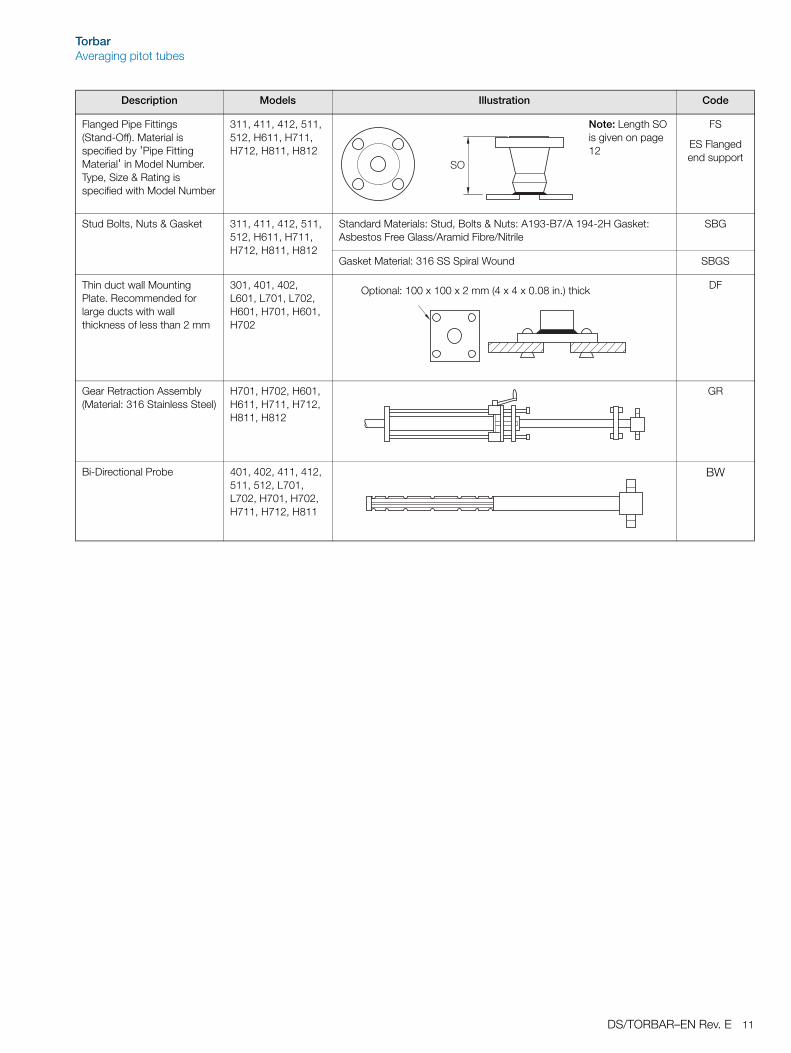
Flanged Pipe Fittings (Stand-Off). Material is specified by 'Pipe Fitting Material' in Model Number. Type, Size & Rating is specified with Model Number
Optional: 100 x 100 x 2 mm (4 x 4 x 0.08 in.) thick
TorbarAveraging pitot tubes
12 DS/TORBAR–EN Rev. E
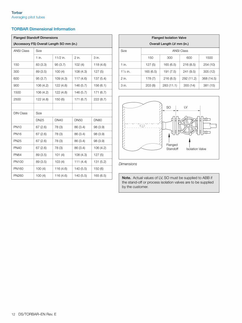
TORBAR Dimensional Information
Flanged Standoff Dimensions
(Accessory FS) Overall Length SO mm (in.)
ANSI Class Size
1 in. 11/2 in. 2 in. 3 in.
150 83 (3.3) 95 (3.7) 102 (4) 118 (4.6)
300 89 (3.5) 100 (4) 108 (4.3) 127 (5)
600 95 (3.7) 109 (4.3) 117 (4.6) 137 (5.4)
900 106 (4.2) 122 (4.8) 146 (5.7) 156 (6.1)
1500 106 (4.2) 122 (4.8) 146 (5.7) 171 (6.7)
2500 122 (4.8) 150 (6) 171 (6.7) 222 (8.7)
DIN Class Size
DN25 DN40 DN50 DN80
PN10 67 (2.6) 78 (3) 86 (3.4) 98 (3.9)
PN16 67 (2.6) 78 (3) 86 (3.4) 98 (3.9)
PN25 67 (2.6) 78 (3) 86 (3.4) 98 (3.9)
PN40 67 (2.6) 78 (3) 86 (3.4) 106 (4.2)
PN64 89 (3.5) 101 (4) 108 (4.3) 127 (5)
PN100 89 (3.5) 103 (4) 111 (4.4) 131 (5.2)
PN160 100 (4) 116 (4.6) 140 (5.5) 150 (6)
PN260 100 (4) 116 (4.6) 140 (5.5) 165 (6.5)
Flanged Isolation Valve
Overall Length LV mm (in.)
Size ANSI Class
150 300 600 1500
1 in. 127 (5) 165 (6.5) 216 (8.5) 254 (10)
11/2 in. 165 (6.5) 191 (7.5) 241 (9.5) 305 (12)
2 in. 178 (7) 216 (8.5) 292 (11.2) 368 (14.5)
3 in. 203 (8) 283 (11.1) 355 (14) 381 (15)
Dimensions
Note. Actual values of LV, SO must be supplied to ABB if the stand-off or process isolation valves are to be supplied by the customer.
Flanged Standoff Isolation Valve
LVSO
TorbarAveraging pitot tubes
DS/TORBAR–EN Rev. E 13
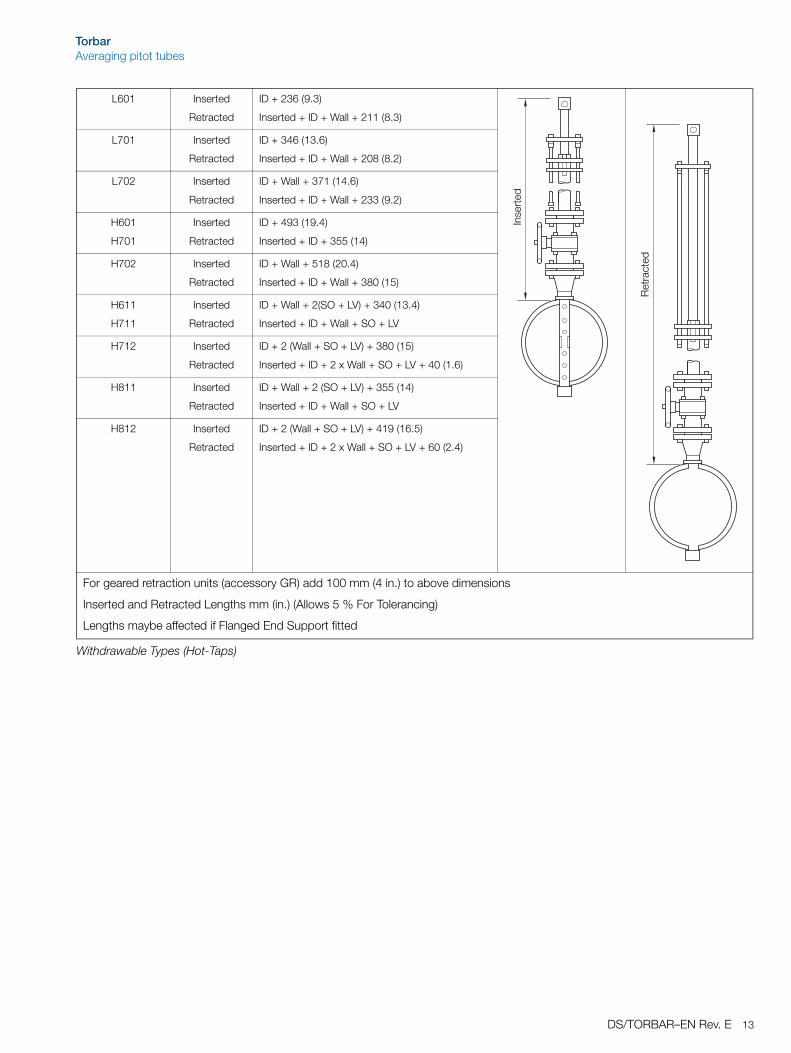
L601 Inserted
Retracted
ID + 236 (9.3)
Inserted + ID + Wall + 211 (8.3)
L701 Inserted
Retracted
ID + 346 (13.6)
Inserted + ID + Wall + 208 (8.2)
L702 Inserted
Retracted
ID + Wall + 371 (14.6)
Inserted + ID + Wall + 233 (9.2)
H601
H701
Inserted
Retracted
ID + 493 (19.4)
Inserted + ID + 355 (14)
H702 Inserted
Retracted
ID + Wall + 518 (20.4)
Inserted + ID + Wall + 380 (15)
H611
H711
Inserted
Retracted
ID + Wall + 2(SO + LV) + 340 (13.4)
Inserted + ID + Wall + SO + LV
H712 Inserted
Retracted
ID + 2 (Wall + SO + LV) + 380 (15)
Inserted + ID + 2 x Wall + SO + LV + 40 (1.6)
H811 Inserted
Retracted
ID + Wall + 2 (SO + LV) + 355 (14)
Inserted + ID + Wall + SO + LV
H812 Inserted
Retracted
ID + 2 (Wall + SO + LV) + 419 (16.5)
Inserted + ID + 2 x Wall + SO + LV + 60 (2.4)
For geared retraction units (accessory GR) add 100 mm (4 in.) to above dimensions
Inserted and Retracted Lengths mm (in.) (Allows 5 % For Tolerancing)
Lengths maybe affected if Flanged End Support fitted
Withdrawable Types (Hot-Taps)
Inse
rted
Ret
ract
ed
TorbarAveraging pitot tubes
14 DS/TORBAR–EN Rev. E
Independent Test ReportsA range of TORBAR models and sizes have been tested at Independent Flow Laboratories to determine the accuracy andrepeatability of measurement. Those tests were conducted in both Air and Water.
Full details of the test results above and of those shown in the table below are available on request.
Model 401 – Size: 16 in. – Serial No. Test 597
Model 401 – Size: 12 in. – Serial No. 20153
Test Fluid Model Size mm (in.) Serial Number Error Band
Water 123 50 (2) Test 197 +0.2 to -0.43 %
Water 301 100 (4) Test 297 +1 to -1 %
Air 401 150 (6) Test 397 +0.1 to -0.5 %
Air 402 450 (18) 20186 +0.6 to -0.5 %
Water 411 600 (24) Test 697 +0.3 to -0.4 %
Kg/hr (lb/h)
400000(883000)
500000(1103750)
600000(1324500)
700000(1545250)
800000(1766000)
900000(1986755)
1000000(2207505)
1100000(2428260)
K F
acto
r
0.88
0.83
0.73
0.68
0.63
0.93
0.78
Water
Error Band: +0.4 % to –0.8 %
K F
acto
r
0.84
0.79
0.74
0.69
0.64
0.59
0.54
Air
Error Band: +0.3 % to –0.5 %
Kg/hr (lb/h)
400(880)
900(1985)
1400(3090)
1900(4195)
2400(5300)
29006400)
3400(7505)
3900(8610)
4400(2870)
4900(9710)
5400(11920)
5900(13025)
TorbarAveraging pitot tubes
DS/TORBAR–EN Rev. E 15
Differential Pressure Calculations & Resonance Frequency Check
Flow to DPLiquids (Volumetric)
Gases (Volumetric)
Liquids / Gases / Steam (Mass)
DP to FlowLiquids (Volumetric)
Gases (Volumetric) – Actual Conditions
Gases (Volumetric) – Normal Conditions
Liquids / Gases / Steam (Mass)
Symbols & UnitsQA = Flow (m3/h)
QB = Flow (Nm3/h) at 0 °C, 1 atm (1.01325 bar)
QC = Flow (kg/h)
QD = Flow (Am3/h)
S = Specific gravity (Air = 1)
D = Density at actual conditions (kg/m3)Base Density of water at 4 °C = 999.972 kg/m3
Density of water at 15.555 °C = 999.012 kg/m3
Base Density of Air at 0 °C1 atm (1.01325 bar) = 1.293 kg/m3
A = Pipe internal cross-section area (cm2)
Tf = Actual temperature (°C)
Pf = Actual pressure (bar Absolute)
K = TORBAR coefficient (see table)
Z = Compressibility factor (usually = 1)
DP = Differential Pressure (mbar)
Normal Conditions 0 °C, 1 Atmosphere (1.01325 bar)
TORBAR Coefficient K
Model Number
Pipe Size
(Internal diameter)
mm (in.)
301 601
311
611
401 402
411 412
701 702
711 712
511 512
811 812
50 (2) 0.6483
75 (3) 0.7027
100 (4) 0.7497 0.6174
150 (6) 0.7671 0.6505
200 (8) 0.6647
250 (10) 0.6794 0.6876
300 (12) 0.6941 0.7024
350 (14) 0.7160 0.7303
400 (16) 0.7380 0.7564
450 (18) 0.7402 0.7699
600 (24) 0.7468 0.7815
900 (36) 0.7473 0.7847
1200 (48) 0.7475 0.7849
1500 (60) 0.7476 0.7850
1800 (72) and above 0.7476 0.7850
For sizes not shown above, determine K by extrapolation.
If using classical flow equations from ISO5167, multiply K by 0.9091.
Copies of derivation of equations available on request.
For Models 121, 122, 123 (all sizes) K = 1
TORBAR Coefficients
DP QAx DKxAx4.6285---------------------------------
Statement of AccuracyThe calculated differential pressure will lie within an uncertaintyband of ± 1 % with 95 % confidence if the TORBAR is installedstrictly in accordance with the published Installation Instructions.For applications which do not conform to those instructions, it isrecommended that an on site calibration is performed in order toachieve the optimum accuracy.
Resonance Frequency CheckThis check is not necessary for liquid flows because themaximum allowable DP is reached before resonance occurs(see table opposite), or for Models 121, 122, and 123. For Gasand Vapour flows a Resonance Frequency Check MUST bemade. Equations have been derived for the various TORBARmodels to determine low and high critical velocities (VL and VH)which define the narrow resonance band of velocities whichshould be outside the continuous operating flow range of theTORBAR.
The following table lists the equations to calculate the values ofVL and VH. If the calculation shows VL to VH to be within thecontinuous operating flow range, then an alternative, suitablemodel of TORBAR should be selected to give acceptable valuesof VL and VH.
Always check that the maximum flow DP is less than the'Maximum Allowable DP' as shown in the table on page 17.
TORBAR Model
Critical Velocities Unsupported Length L (m)
VL (m/s) VH (m/s)
301 0.472 ÷ L2 0.728 ÷ L2 ID + Wall + 0.05
311 0.472 ÷ L2 0.728 ÷ L2 ID + Wall + SO
L601 0.472 ÷ L2 0.728 ÷ L2 ID + Wall + 0.02
401 1.843 ÷ L2 2.840 ÷ L2 ID + Wall + 0.08 (3)
402 8.08 ÷ L2 12.44 ÷ L2 ID + 2 x Wall + 0.115
411 1.843 ÷ L2 2.840 ÷ L2 ID + Wall + SO
412 8.08 ÷ L2 12.44 ÷ L2 ID + 2 x Wall + SO + 0.05
L701 1.843 ÷ L2 2.840 ÷ L2 ID + Wall + 0.05
L702 8.08 ÷ L2 12.44 ÷ L2 ID + 2 x Wall + 0.10
H601 0.472 ÷ L2 0.728 ÷ L2 ID + Wall + 0.05
H701 1.843 ÷ L2 2.840 ÷ L2 ID + Wall + 0.05
H702 8.08 ÷ L2 12.44 ÷ L2 ID + 2 x Wall + 0.10
H611 0.472 ÷ L2 0.728 ÷ L2 ID + Wall + SO + LV + 0.05
H711 1.843 ÷ L2 2.840 ÷ L2 ID + Wall + SO + LV + 0.05
H712 8.08 ÷ L2 12.44 ÷ L2 ID + 2 x Wall + SO + LV + 0.10
511 10.88 ÷ L2 16.766 ÷ L2 ID + Wall + SO
512 47.65 ÷ L2 73.43 ÷ L2 ID + 2 x Wall + SO + 0.08
H811 10.88 ÷ L2 16.766 ÷ L2 ID + Wall + SO + LV + 0.05
H812 47.65 ÷ L2 73.43 ÷ L2 ID + 2 x Wall + SO + LV + 0.13
L = Unsupported Length (Metres)
ID = Pipe Internal Diameter (Metres)
Wall = Pipe Wall Thickness (Metres)
SO = Overall Length of Flanged Pipe Fitting (m) – see page 9
LV = Overall Length of Isolation Valve (m) – see page 9
The above equations are derived from TORBAR resonance frequencydata and calculations. Full details are available on request.
Critical Velocity Calculation
TorbarAveraging pitot tubes
DS/TORBAR–EN Rev. E 17
Maximum Allowable DPDepending on the model and size of TORBAR there is amaximum figure of Differential Pressure above which theTORBAR should NOT be used due to the imposition ofexcessive mechanical stresses. Check the table below to ensurethat the application is suitable. If the calculated DP exceeds themaximum shown below, then select an other appropriate modelto suit the application. For Bi-Directional configurations(accessory code BW), use 50 % of the figures in this table.
For liquid flow applications where there is a possibility of processpulsations or intermittent excessive flow velocity, then theend-support models should always be selected for pipe sizesover 250 mm (10 in.) diameter (400 and 700 series) and 600mm (24 in.) (500 and 800 series).
For Sizes Not Shown Above Determine Maximum Allowable DP By Extrapolation
* For models 121, 122, 123 (all sizes) Maximum DP value is 2500 mbar. (84 in.wg)
The above figures are theoretically derived and include a x10 safety factor over and above basic standards and specification. Full theoretical data is available on request.
TorbarAveraging pitot tubes
18 DS/TORBAR–EN Rev. E
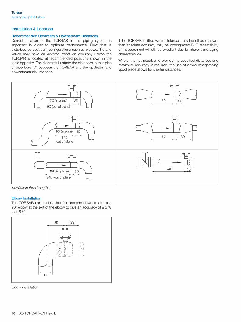
Installation & Location
Recommended Upstream & Downstream DistancesCorrect location of the TORBAR in the piping system isimportant in order to optimize performance. Flow that isdisturbed by upstream configurations such as elbows, T's andvalves may have an adverse effect on accuracy unless theTORBAR is located at recommended positions shown in thetable opposite. The diagrams illustrate the distances in multiplesof pipe bore 'D' between the TORBAR and the upstream anddownstream disturbances.
If the TORBAR is fitted within distances less than those shown,then absolute accuracy may be downgraded BUT repeatabilityof measurement will still be excellent due to inherent averagingcharacteristics.
Where it is not possible to provide the specified distances andmaximum accuracy is required, the use of a flow straighteningspool piece allows for shorter distances.
Elbow InstallationThe TORBAR can be installed 2 diameters downstream of a90° elbow at the exit of the elbow to give an accuracy of ± 3 %to ± 5 %.
Installation Pipe Lengths
7D (in plane)
9D (out of plane)
3D 3D8D
9D (in plane)
14D(out of plane)
3D
3D8D
19D (in plane)
24D (out of plane)
3D4D24D
Elbow Installation
3D2D
D
TorbarAveraging pitot tubes
DS/TORBAR–EN Rev. E 19
Orientation in PipeThe TORBAR must be installed at right angles to the pipe runand across a pipe diameter within the tolerances shown in thediagrams opposite.
To avoid 'noisy' signal outputs, do not locate the TORBAR in apulsating flow. A vibrating pipe can also distort the output signaland affect the structural limits of the TORBAR. This limitationparticularly applies to the integrally mounted transmitter optionDM3V and to the TRIBAR configuration.
For vertical pipe applications, the 'head' of the TORBAR isrepositioned to ensure that DP connections are at the samevertical level. This is option VS. It is necessary to specify thisoption when ordering the TORBAR.
It is essential that in all steam installations the entire TORBARhead and fitting assembly are well lagged to prevent theformation of condensate in the TORBAR head. The TORBARwill not function correctly with condensate in the head. Fillingtees or condensate pots should be fitted as appropriate.
Before installation or removal of a TORBAR it is imperative thatcareful reference is made to the appropriate installationinstructions that are supplied with each TORBAR shipment. Theinstallation instructions are also available separately on request.
Warning. Refer to instruction manual before installing any TORBAR flowmeter.
General Orientation
Gases
Steam
Liquids
��
5 o5 o (Maximum)
Flow
5 o min 5 o min
Horizontal Pipe(side view)
Vertical Pipe(top view)
Horizontal Pipe(side view)
Vertical Pipe(top view)
Horizontal Pipe(side view)
Vertical Pipe (VS)(top view)
5 o min 5 o min
TorbarAveraging pitot tubes
20 DS/TORBAR–EN Rev. E
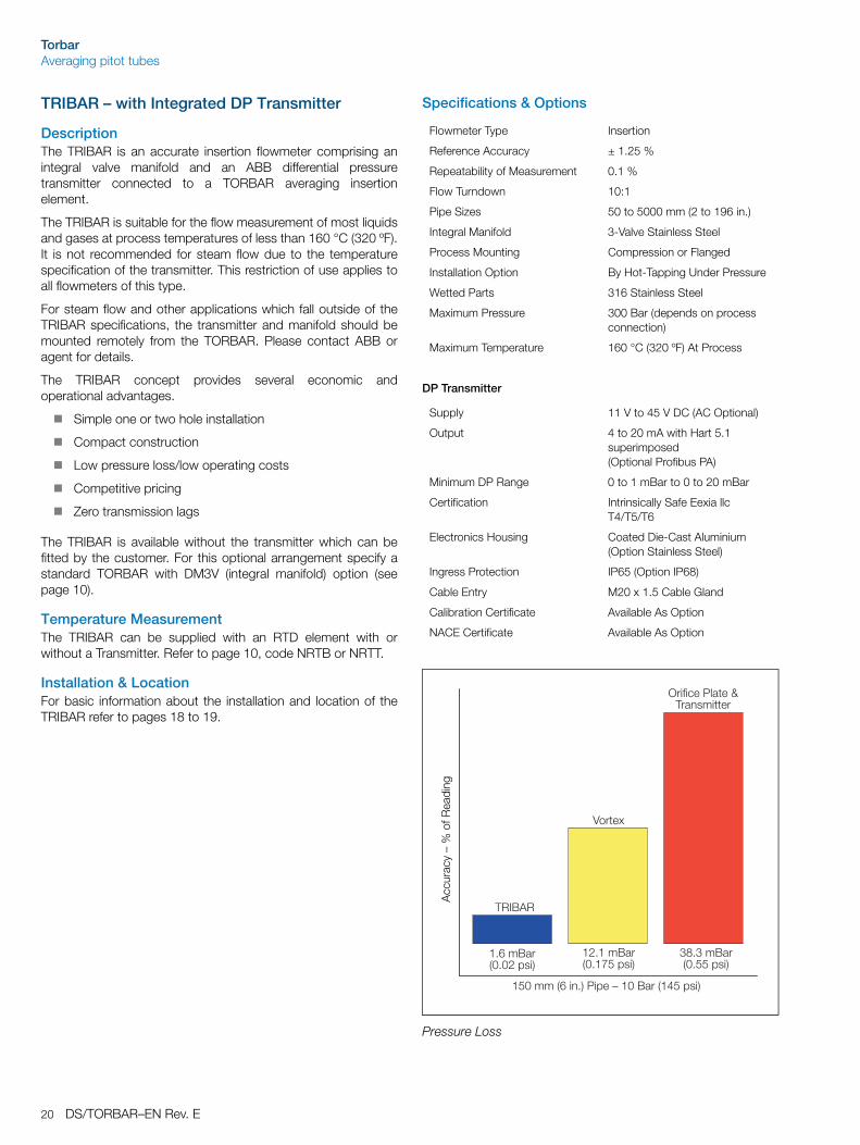
TRIBAR – with Integrated DP Transmitter
DescriptionThe TRIBAR is an accurate insertion flowmeter comprising anintegral valve manifold and an ABB differential pressuretransmitter connected to a TORBAR averaging insertionelement.
The TRIBAR is suitable for the flow measurement of most liquidsand gases at process temperatures of less than 160 °C (320 ºF).It is not recommended for steam flow due to the temperaturespecification of the transmitter. This restriction of use applies toall flowmeters of this type.
For steam flow and other applications which fall outside of theTRIBAR specifications, the transmitter and manifold should bemounted remotely from the TORBAR. Please contact ABB oragent for details.
The TRIBAR concept provides several economic andoperational advantages.
Simple one or two hole installation
Compact construction
Low pressure loss/low operating costs
Competitive pricing
Zero transmission lags
The TRIBAR is available without the transmitter which can befitted by the customer. For this optional arrangement specify astandard TORBAR with DM3V (integral manifold) option (seepage 10).
Temperature MeasurementThe TRIBAR can be supplied with an RTD element with orwithout a Transmitter. Refer to page 10, code NRTB or NRTT.
Installation & LocationFor basic information about the installation and location of theTRIBAR refer to pages 18 to 19.
Specifications & Options
DP Transmitter
Flowmeter Type Insertion
Reference Accuracy ± 1.25 %
Repeatability of Measurement 0.1 %
Flow Turndown 10:1
Pipe Sizes 50 to 5000 mm (2 to 196 in.)
Integral Manifold 3-Valve Stainless Steel
Process Mounting Compression or Flanged
Installation Option By Hot-Tapping Under Pressure
Wetted Parts 316 Stainless Steel
Maximum Pressure 300 Bar (depends on process connection)
Maximum Temperature 160 °C (320 ºF) At Process
Supply 11 V to 45 V DC (AC Optional)
Output 4 to 20 mA with Hart 5.1 superimposed (Optional Profibus PA)
DescriptionThe MASS TRIBAR is an insertion flowmeter comprising anintegral valve manifold, a PT100 temperature element and anABB Smart Multivariable Transmitter attached to a TORBARaveraging flow element.
The MASS TRIBAR measures pressure, temperature anddifferential pressure directly from the TORBAR and computesthe compensated mass flow within the MV transmitter byautomatically compensating for fluctuations in temperature andpressure.
The MASS TRIBAR is ideally suited for the flow measurement ofliquids and gases and the totally integrated concept providesseveral direct advantages.
Averaged Flow Profile Measurement
Simple One or Two Hole Installation
Compact Integral Construction
RTD Easily Removable for Maintenance
Zero Transmission Lags
Low Pressure Loss/Low Operating Costs
Single Product Sourcing
Application LimitationFor steam flow and other applications which fall outside of theMASS TRIBAR specifications, the multivariable transmitter andmanifold should be mounted remotely. Please contact ABB orAgent for details of that arrangement.
Installation & LocationFor the basic information about the installation and location ofthe MASS TRIBAR refer to page 17. Refer to the MV Transmitterdata sheet for the transmitter calibration and set-up informationand procedures.
Specification
Accuracy ± 1 % Flow +0.1 % of calibrated span
Repeatability Of Measurement 0.2 %
Flowrange Turndown 10 to 1
Temperature Element RTD 4-Wire
Maximum Pressure 100 Bar (1450 psi)
Maximum Temperature at Manifold/Transmitter Face
80 °C (176 ºF)
Minimum Temperature at Manifold/Transmitter Face
–50 °C (–58 ºF)
Ambient Temperature Range –40 °C to 85 °C (–40 to 185 ºF)
System 2-Wire (11 V to 45 V DC) external power supply required
Output 2-Wire 4 to 20 mA linear to mass flow
Digital HART protocol available to host which conforms to the HART protocol
Pressure, temperature and DP variables are available through HART
Process Indicator Integral, 2-line, 6-character
Protection: IP67. EEXia II CT4/T5/T6
Wetted Parts 316 Stainless steel
Pipe Sizes 100 mm to 5000 mm (4 to 196 in.)
Stability ± 0.1 % URL for 12 months
TorbarAveraging pitot tubes
22 DS/TORBAR–EN Rev. E
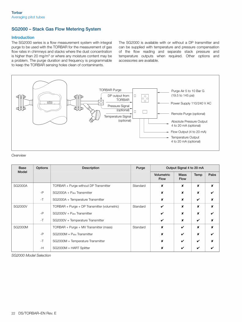
SG2000 – Stack Gas Flow Metering System
IntroductionThe SG2000 series is a flow measurement system with integralpurge to be used with the TORBAR for the measurement of gasflow rates in chimneys and stacks where the dust concentrationis higher than 20 mg/m3 or where any moisture content may bea problem. The purge duration and frequency is programmableto keep the TORBAR sensing holes clean of contaminants.
The SG2000 is available with or without a DP transmitter andcan be supplied with temperature and pressure compensationof the flow reading and separate stack pressure andtemperature outputs when required. Other options andaccessories are available.
Overview
Base Model
Options Description Purge Output Signal 4 to 20 mA
Volumetric Flow
Mass Flow
Temp Pabs
SG2000A TORBAR + Purge without DP Transmitter Standard
-P SG2000A + Pabs Transmitter
-T SG2000A + Temperature Transmitter
SG2000V TORBAR + Purge + DP Transmitter (volumetric) Standard
-P SG2000V + Pabs Transmitter
-T SG2000V + Temperature Transmitter
SG2000M TORBAR + Purge + MV Transmitter (mass) Standard
-P SG2000M + Pabs Transmitter
-T SG2000M + Temperature Transmitter
-H SG2000M + HART Splitter
SG2000 Model Selection
TORBAR Purge
DP output fromTORBAR
Pressure Signal(optional)
Temperature Signal(optional)
Power Supply 110/240 V AC
Remote Purge (optional)
Absolute Pressure Output 4 to 20 mA (optional)
Flow Output (4 to 20 mA)
Temperature Output 4 to 20 mA (optional)
Purge Air 5 to 10 Bar G(19.5 to 145 psi)
TorbarAveraging pitot tubes
DS/TORBAR–EN Rev. E 23
Specifications
Performance SpecificationsSquare root extraction of flow DP.
The purge sequence is programmed by a programmable logic controller (PLC) and can be adjusted to purge once every one minute to once every 24 hours. The length of the purge time can be adjusted from one minute to 100 minutes.
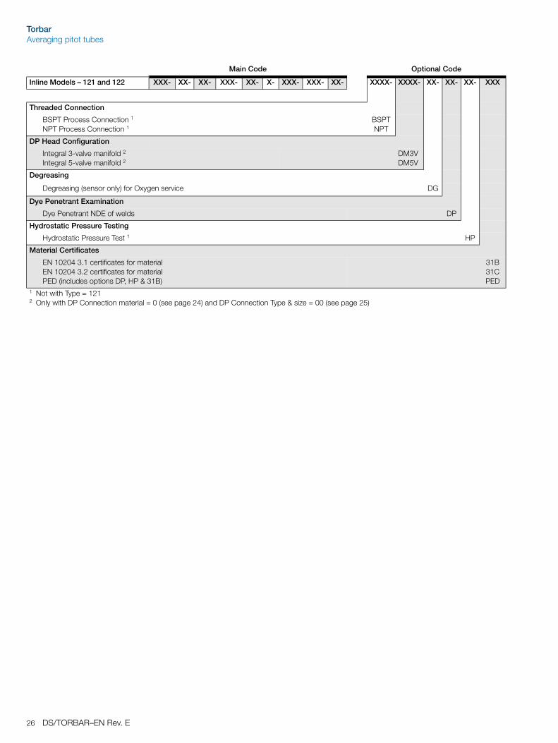
1 Only with DP Connection material = 0 2 Only with DP Connection material = B, S3 Only with DP Connection material = S 4 Only with DP Connection material = S, H 5 Only with DP Connection material = S, M 6 Only with DP Connection material = S, M, H 7 Only with DP Connection material = C, S 8 Only with DP Connection material = C
1 Only with DP Connection material = 0 2 Only with DP Connection material = B, S3 Only with DP Connection material = S 4 Only with DP Connection material = S, H 5 Only with DP Connection material = S, M 6 Only with DP Connection material = S, M, H 7 Only with DP Connection material = C, S 8 Only with DP Connection material = C
Continued on next page
Main Code Optional Code
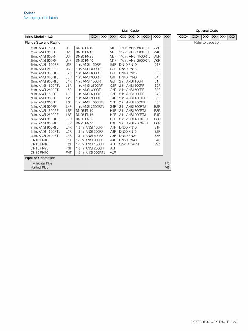
Inline Model – 123 XXX- XX- XX- XXX XX X XXX- XXX- XX- XXXX- XXX- XX- XX- XX- XXX
TorbarAveraging pitot tubes
DS/TORBAR–EN Rev. E 29
Flange Size and Rating Refer to page 30.
½ in. ANSI 150RF½ in. ANSI 300RF½ in. ANSI 600RF½ in. ANSI 900RF½ in. ANSI 1500RF½ in. ANSI 2500RF½ in. ANSI 300RTJ½ in. ANSI 600RTJ½ in. ANSI 900RTJ½ in. ANSI 1500RTJ½ in. ANSI 2500RTJ¾ in. ANSI 150RF¾ in. ANSI 300RF¾ in. ANSI 600RF¾ in. ANSI 900RF¾ in. ANSI 1500RF¾ in. ANSI 2500RF¾ in. ANSI 300RTJ¾ in. ANSI 600RTJ¾ in. ANSI 900RTJ¾ in. ANSI 1500RTJ¾ in. ANSI 2500RTJDN15 PN10DN15 PN16DN15 PN25DN15 PN40
DN20 PN10DN20 PN16DN20 PN25DN20 PN401 in. ANSI 150RF1 in. ANSI 300RF1 in. ANSI 600RF1 in. ANSI 900RF1 in. ANSI 1500RF1 in. ANSI 2500RF1 in. ANSI 300RTJ1 in. ANSI 600RTJ1 in. ANSI 900RTJ1 in. ANSI 1500RTJ1 in. ANSI 2500RTJDN25 PN10DN25 PN16DN25 PN25DN25 PN401½ in. ANSI 150RF1½ in. ANSI 300RF1½ in. ANSI 600RF1½ in. ANSI 900RF1½ in. ANSI 1500RF1½ in. ANSI 2500RF1½ in. ANSI 300RTJ
1½ in. ANSI 600RTJ1½ in. ANSI 900RTJ1½ in. ANSI 1500RTJ1½ in. ANSI 2500RTJDN40 PN10DN40 PN16DN40 PN25DN40 PN402 in. ANSI 150RF2 in. ANSI 300RF2 in. ANSI 600RF2 in. ANSI 900RF2 in. ANSI 1500RF2 in. ANSI 2500RF2 in. ANSI 300RTJ2 in. ANSI 600RTJ2 in. ANSI 900RTJ2 in. ANSI 1500RTJ2 in. ANSI 2500RTJDN50 PN10DN50 PN16DN50 PN25DN50 PN40Special flange
Threaded Fitting for pipe sizes DN50 to DN150Threaded Fitting for pipe sizes DN100 to DN1800Threaded Fitting with end support for pipe sizes DN100 to DN5000Flanged Fitting for pipe sizes DN50 to DN150Flanged Fitting for pipe sizes DN100 to DN1800Flanged Fitting for pipe sizes DN200 to DN1800Flanged Fitting with end support for pipe sizes DN100 to DN5000Flanged Fitting with end support for pipe sizes DN300 to DN5000
301401402
311411511412
512
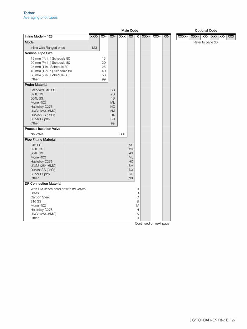
Nominal Pipe Size
Nominally 50 mm inside diameter 1
(specify actual id which must be in range 44...61 mm)Nominally 75 mm inside diameter 1
(specify actual id which must be in range 62...87 mm)Nominally 100 mm inside diameter 2
(specify actual id which must be in range 88...111 mm)Nominally 125 mm inside diameter 2 (specify actual id which must be in range 112...137 mm)Nominally 150 mm inside diameter 2 (specify actual id which must be in range 138...174 mm)Nominally 200 mm inside diameter 2 (specify actual id which must be in range 175...224 mm)Nominally 250 mm inside diameter 2 (specify actual id which must be in range 225...274 mm)Nominally 300 mm inside diameter (specify actual id which must be in range 275...324 mm)Nominally 350 mm inside diameter (specify actual id which must be in range 325...374 mm)Nominally 400 mm inside diameter (specify actual id which must be in range 375...424 mm)Nominally 450 mm inside diameter (specify actual id which must be in range 425...474 mm)Nominally 500 mm inside diameter (specify actual id which must be in range 475...549 mm)Nominally 600 mm inside diameter (specify actual id which must be in range 550...674 mm)Nominally 750 mm inside diameter (specify actual id which must be in range 675...824 mm)Nominally 900 mm inside diameter (specify actual id which must be in range 825...924 mm)Nominally 1000 mm inside diameter (specify actual id which must be in range 925...1024 mm)
.
.
.
Nominally 5000 mm inside diameter 3
(specify actual ID which must be in range 4925...5024 mm)Other
0050
0075
0100
0125
0150
0200
0250
0300
0350
0400
0450
0500
0600
0750
0900
1000
.
.
.
5000
9999
Continued on next page
TorbarAveraging pitot tubes
32 DS/TORBAR–EN Rev. E
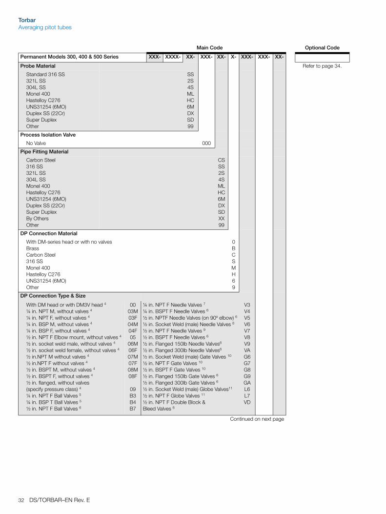
Probe Material Refer to page 34.
Standard 316 SS321L SS304L SSMonel 400Hastelloy C276UNS31254 (6MO)Duplex SS (22Cr)Super DuplexOther
1 301, 311 only2 Not 5123 Type = 402, 412, 512 only4 Only with DP Connection material = 0 5 Only with DP Connection material = B, S6 Only with DP Connection material = S 7 Only with DP Connection material = S, H8 Only with DP Connection material = S, M9 Only with DP Connection material = S, M, H10 Only with DP Connection material = C, S 11 Only with DP Connection material = C 12 301, 401,402 only13 311 only14 411,412 only15 511,512 only16 311, 411,412, 511, 512 only
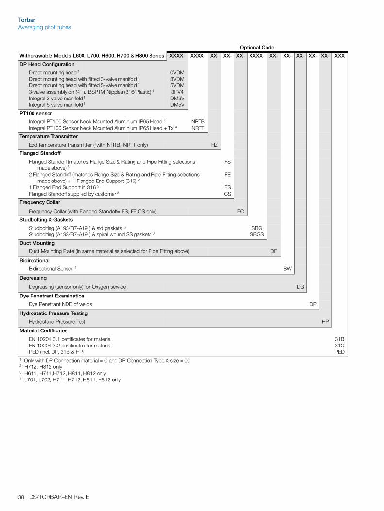
Direct mounting head with fitted 3-valve manifold 1
Direct mounting head with fitted 5-valve manifold 1
3-valve assembly on ¼" BSPTM Nipples (316/Plastic) 1
Integral 3-valve manifold 1
Integral 5-valve manifold 1
0VDM3VDM5VDM3PV4DM3VDM5V
PT100 sensor
Integral PT100 Sensor Neck Mounted Aluminium IP65 Head 6
Integral PT100 Sensor Neck Mounted Aluminium IP65 Head + Tx 6NRTBNRTT
Temperature Transmitter
Exd temperature Transmitter (with NRTB, NRTT only) 6 HZ
Flanged Standoff
Flanged Standoff (matches Flange Size & Rating and Pipe Fitting selections made above) 2
2 Flanged Standoff (matches Flange Size & Rating and Pipe Fitting selections made above)+ 1 Flanged End Support (316) 3
1 Flanged End Support in 316 3
Flanged Standoff supplied by customer 4
FS
FE
ESCS
Frequency Collar
Frequency Collar (with Flanged Standoff= FS, FE,CS only) 4 FC
Studbolting & Gaskets
Studbolting (A193/B7-A19 ) & standard gaskets 4
Studbolting (A193/B7-A19 ) & spiral-wound SS gaskets 4SBG
SBGS
Duct Mounting
Duct Mounting Plate (in same material as selected for Pipe Fitting above) 5 DF
Bidirectional
Bidirectional Sensor 6 BW
Degreasing
Degreasing (sensor only) for Oxygen service DG
Dye Penetrant Examination
Dye Penetrant NDE of welds DP
Hydrostatic Pressure Testing
Hydrostatic Pressure Test HP
Material Certificates
EN 10204 3.1 certificates for materialEN 10204 3.2 certificates for materialPED (incl. DP, 31B & HP)
31B31CPED
1 Only with DP Connection material = 0 and DP Connection Type & size = 002 311, 411, 412, 511, 512 only3 412, 512 only4 411, 412, 511, 512 only5 301, 401, 402 only6 401, 402, 411, 412, 511, 512 only
TorbarAveraging pitot tubes
DS/TORBAR–EN Rev. E 35
Main Code Optional Code
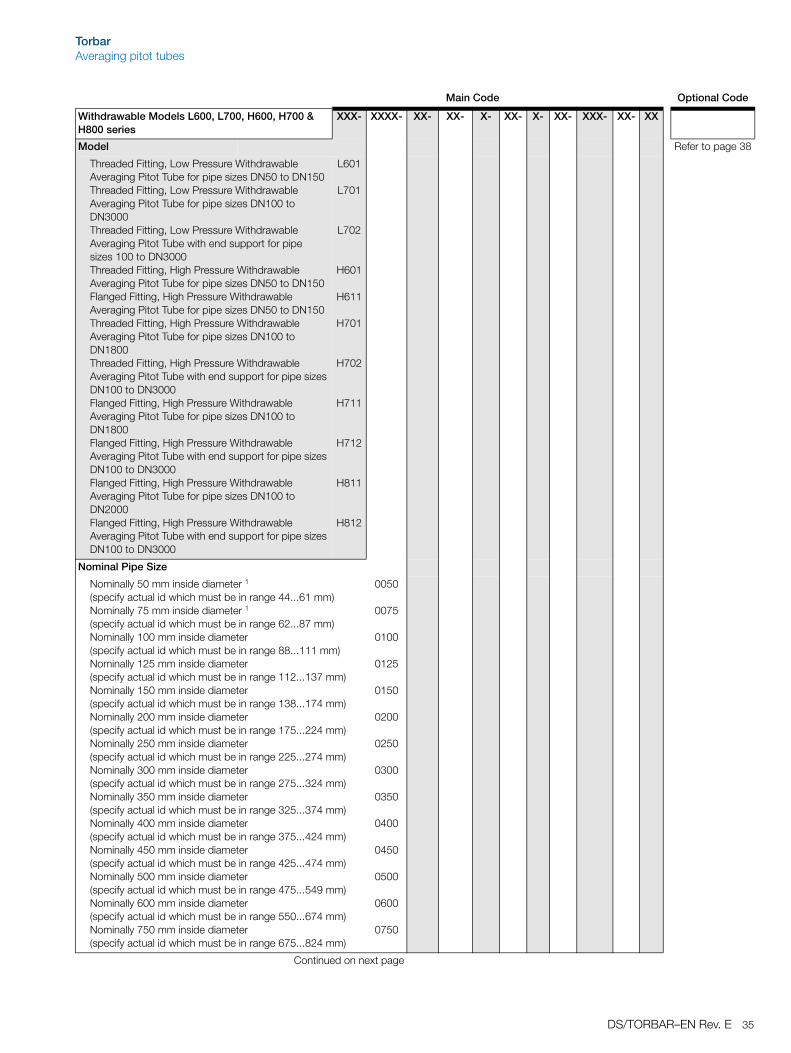
Withdrawable Models L600, L700, H600, H700 & H800 series
XXX- XXXX- XX- XX- X- XX- X- XX- XXX- XX- XX
Model Refer to page 38
Threaded Fitting, Low Pressure Withdrawable Averaging Pitot Tube for pipe sizes DN50 to DN150Threaded Fitting, Low Pressure Withdrawable Averaging Pitot Tube for pipe sizes DN100 to DN3000Threaded Fitting, Low Pressure Withdrawable Averaging Pitot Tube with end support for pipe sizes 100 to DN3000Threaded Fitting, High Pressure Withdrawable Averaging Pitot Tube for pipe sizes DN50 to DN150Flanged Fitting, High Pressure Withdrawable Averaging Pitot Tube for pipe sizes DN50 to DN150Threaded Fitting, High Pressure Withdrawable Averaging Pitot Tube for pipe sizes DN100 to DN1800Threaded Fitting, High Pressure Withdrawable Averaging Pitot Tube with end support for pipe sizes DN100 to DN3000Flanged Fitting, High Pressure Withdrawable Averaging Pitot Tube for pipe sizes DN100 to DN1800Flanged Fitting, High Pressure Withdrawable Averaging Pitot Tube with end support for pipe sizes DN100 to DN3000Flanged Fitting, High Pressure Withdrawable Averaging Pitot Tube for pipe sizes DN100 to DN2000Flanged Fitting, High Pressure Withdrawable Averaging Pitot Tube with end support for pipe sizes DN100 to DN3000
L601
L701
L702
H601
H611
H701
H702
H711
H712
H811
H812
Nominal Pipe Size
Nominally 50 mm inside diameter 1
(specify actual id which must be in range 44...61 mm)Nominally 75 mm inside diameter 1
(specify actual id which must be in range 62...87 mm)Nominally 100 mm inside diameter (specify actual id which must be in range 88...111 mm)Nominally 125 mm inside diameter (specify actual id which must be in range 112...137 mm)Nominally 150 mm inside diameter (specify actual id which must be in range 138...174 mm)Nominally 200 mm inside diameter (specify actual id which must be in range 175...224 mm)Nominally 250 mm inside diameter (specify actual id which must be in range 225...274 mm)Nominally 300 mm inside diameter (specify actual id which must be in range 275...324 mm)Nominally 350 mm inside diameter (specify actual id which must be in range 325...374 mm)Nominally 400 mm inside diameter (specify actual id which must be in range 375...424 mm)Nominally 450 mm inside diameter (specify actual id which must be in range 425...474 mm)Nominally 500 mm inside diameter (specify actual id which must be in range 475...549 mm)Nominally 600 mm inside diameter (specify actual id which must be in range 550...674 mm)Nominally 750 mm inside diameter (specify actual id which must be in range 675...824 mm)
0050
0075
0100
0125
0150
0200
0250
0300
0350
0400
0450
0500
0600
0750
Continued on next page
TorbarAveraging pitot tubes
36 DS/TORBAR–EN Rev. E
Nominal Pipe Size (continued) Refer to page 38
Nominally 900 mm inside diameter (specify actual id which must be in range 825...924 mm)Nominally 1000 mm inside diameter (specify actual id which must be in range 925...1024 mm)Nominally 1100 mm inside diameter (specify actual id which must be in range 1025...1124 mm)
.
.
.
Nominally 3000 mm inside diameter 2
(specify actual id which must be in range 2925...3024 mm)Other
0900
1000
1100
.
.
.
3000
9999
Probe Material
Standard 316 SS321L SS304L SSMonel 400Hastelloy C276UNS31254 (6MO)Duplex SS (22Cr)Super DuplexOther
SS2S4SMLHC6MDXSD99
Process Isolation Valve
Threaded Ball Valve ¾ in. 3
Threaded Ball Valve 1¼ in. 15
Flanged Ball Valve 1½ in. 16
Threaded Gate Valve 1¼ in. 15
Flanged Gate Valve 1½ in. 16
Flanged Ball Valve 3 in.Flanged Gate Valve 3 in. Valve supplied by Customer
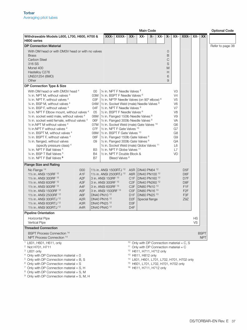
Withdrawable Models L600, L700, H600, H700 & H800 series
XXX- XXXX- XX- XX- X- XX- X- XX- XXX- XX- XX
TorbarAveraging pitot tubes
DS/TORBAR–EN Rev. E 37
DP Connection Material Refer to page 38
With DM head or with DM3V head or with no valvesBrassCarbon Steel316 SSMonel 400Hastelloy C276UNS31254 (6MO)Other
0BCSMH69
DP Connection Type & Size
With DM head or with DM3V head 4
¼ in. NPT M, without valves 4
¼ in. NPT F, without valves 4
¼ in. BSP M, without valves 4
¼ in. BSP F, without valves 4
½ in. NPT F Elbow mount, without valves 4
½ in. socket weld male, without valves 4
½ in. socket weld female, without valves 4
½ in.NPT M without valves 4
½ in.NPT F without valves 4
½ in. BSPT M, without valves 4
½ in. BSPT F, without valves 4
½ in. flanged, without valves (specify pressure class) 4
¼ in. NPT F Ball Valves 5
¼ in. BSP T Ball Valves 5
½ in. NPT F Ball Valves 6
0003M03F04M04F05
06M06F07M07F08M08F09
B3B4B7
¼ in. NPT F Needle Valves 7
¼ in. BSPT F Needle Valves 6
½ in. NPTF Needle Valves (on 90º elbow) 6
½ in. Socket Weld (male) Needle Valves 8
½ in. NPT F Needle Valves 9
½ in. BSPT F Needle Valves 6
½ in. Flanged 150lb Needle Valves 6
½ in. Flanged 300lb Needle Valves 6
½ in. Socket Weld (male) Gate Valves 10
½ in. NPT F Gate Valves 10
½ in. BSPT F Gate Valves 10
½ in. Flanged 150lb Gate Valves 6
½ in. Flanged 300lb Gate Valves 6
½ in. Socket Weld (male) Globe Valves 11
½ in. NPT F Globe Valves 11
½ in. NPT F Double Block & Bleed Valves 6
V3V4V5V6V7V8V9VAG6G7G8G9GAL6L7VD
Flange Size and Rating
No Flange 14
1½ in. ANSI 150RF 12
1½ in. ANSI 300RF 12
1½ in. ANSI 600RF 12
1½ in. ANSI 900RF 12
1½ in. ANSI 1500RF 12
1½ in. ANSI 2500RF 12
1½ in. ANSI 300RTJ 12
1½ in. ANSI 600RTJ 12
1½ in. ANSI 900RTJ 12
000A1FA2FA3FA4FA5FA6FA2RA3RA4R
1½ in. ANSI 1500RTJ 12
1½ in. ANSI 2500RTJ 12
3 in. ANSI 150RF 13
3 in. ANSI 300RF 13
3 in. ANSI 600RF 13
3 in. ANSI 1500RF 13
DN40 PN10 12
DN40 PN16 12
DN40 PN25 12
DN40 PN40 12
A5RA6RC1FC2FC3FC5FD1FD2FD3FD4F
DN40 PN64 12
DN40 PN100 12
DN40 PN160 12
DN40 PN260 12
DN80 PN10 13
DN80 PN16 13
DN80 PN25 13
Special flange
D5FD6FD7FD8FF1FF2FF3FZ9Z
Pipeline Orientation
Horizontal PipeVertical Pipe
HSVS
Threaded Connection
BSPT Process Connection 14
NPT Process Connection 14BSPT
NPT1 L601, H601, H611, only2 Not H701, H7113 L601 only4 Only with DP Connection material = 05 Only with DP Connection material = B, S6 Only with DP Connection material = S 7 Only with DP Connection material = S, H8 Only with DP Connection material = S, M9 Only with DP Connection material = S, M, H
10 Only with DP Connection material = C, S11 Only with DP Connection material = C 12 H611, H711, H712 only13 H811, H812 only14 L601, H601, L701, L702, H701, H702 only15 H601, L701, L702, H701, H702 only16 H611, H711, H712 only
Main Code Optional Code
Withdrawable Models L600, L700, H600, H700 & H800 series
ABB Inc.Process Automation125 E. County Line RoadWarminsterPA 18974USATel: +1 215 674 6000Fax: +1 215 674 7183
www.abb.com
NoteWe reserve the right to make technical changes or modify the contents of this document without prior notice. With regard to purchase orders, the agreed particulars shall prevail. ABB does not accept any responsibility whatsoever for potential errors or possible lack of information in this document.
We reserve all rights in this document and in the subject matter and illustrations contained therein. Any reproduction, disclosure to third parties or utilization of its contents in whole or in parts – is forbidden without prior written consent of ABB.