Table of Contents Getting Started .............................................................................................................................................. 4
Running a Job .......................................................................................................................................... 15
Running a Job without Ohmic Sensing .................................................................................................... 18
G Code Commands .................................................................................................................................. 82
M CODE COMMANDS ............................................................................................................................. 90
Appendix B: VFC Height Control ................................................................................................................. 92
Tips and Tricks ............................................................................................................................................. 93
Searching a Job with the ‘Run From Here’ Feature ................................................................................ 93
Configuring the Homing Sequence using Datum and Over-Travel Switches for Accumove 3 ................ 94
Using a Router with Accumove and Torchmate VMD ............................................................................ 96
Using Accumove with a Vinyl Cutter ....................................................................................................... 97
Lincoln Electric
Torchmate VMD User Manual
4
4 | P a g e
Getting Started
Minimum System Requirements
Windows 7 or newer
1 GHz Processor
2 GB RAM
400 MB Available Hard Drive Space
Installing Torchmate Visual Machine Designer
The installer file for Torchmate Visual Machine Designer is named TM-VMD_Setup_Version.exe where
the version will change as new versions of the software are released. The setup file is included on the
USB dongle that is delivered with your machine purchase; but is also always available for download on
the Torchmate website at this location:
http://torchmate.com/driver-software-downloads
If using the setup file that comes on the USB dongle, copy the file to your desktop before running the
installer.
Before running the installer, make sure that your Windows User has all administrative rights for the
computer. You will also need Admin rights to properly run the software. If the computer is a personal
computer or it was purchased from Torchmate this won’t be a concern; however if this computer is on a
corporate network an IT administrator may need to be contacted regarding these permissions.
Once the setup file has been copied to your hard drive and a user with Admin rights is logged in, double
click the setup file to run the installer. Follow the installation wizard, keeping all of the default options
enabled, to install Torchmate Visual Machine Designer.
Registering the Torchmate VMD Software
When the software is installed a 30 day trial begins. In order to continue using the software after the 30
day trial expires you must call or e-mail the Torchmate Technical Support Group and request a VMD
license. When requesting the license, be sure have your VMD Registration ID (this is an 8 character code
displayed on the registration screen) and your customer ID or order number from your sales order.
A VMD license will only work on the computer that it was generated for. If you would like to run the
VMD software on multiple computers you will just need to request another set of license codes from the
Tech Support team.
Lincoln Electric
Torchmate VMD User Manual
5
5 | P a g e
Once the license information is received from Torchmate you will need to enter the Unlock Code and
the Registration ID on the registration screen to unlock the software. To access the 'unlock' screen, click
the 'Register' tab on the top of the startup window and enter the provided information in the
appropriate text boxes.
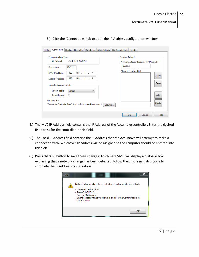
Connecting to the Accumove Controller
Before you can control your machine with the VMD software you will need to establish a connection to
the Accumove controller. The Accumove motion controller connects to a host computer using a network
connection. In order to establish this connection, the controller is expecting to connect to a specific IP
address: 192.168.1.6. You will need to change the IP address of your computer to 192.168.1.6 in order
to connect to the controller.
There are two ways you can set the IP address of your computer: manually (using Windows) or
automatically (using the VMD software).
Automatically Set the Computers IP Address
1.) Launch the Torchmate VMD Software by double clicking the icon on the desktop.
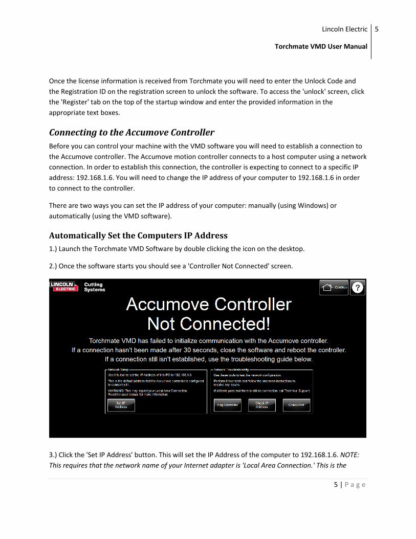
2.) Once the software starts you should see a 'Controller Not Connected' screen.
3.) Click the 'Set IP Address' button. This will set the IP Address of the computer to 192.168.1.6. NOTE:
This requires that the network name of your Internet adapter is 'Local Area Connection.' This is the
Lincoln Electric
Torchmate VMD User Manual
6
6 | P a g e
typical value for a computers Ethernet LAN, but if you aren't able to connect try setting the IP address
manually by following the steps below.
4.) After setting the IP Address it is recommended that you close the Torchmate VMD software and
power down the Accumove controller. After waiting 15 seconds, turn the controller back on and then
open the Torchmate VMD software again.
Manually Set the Computers IP Address
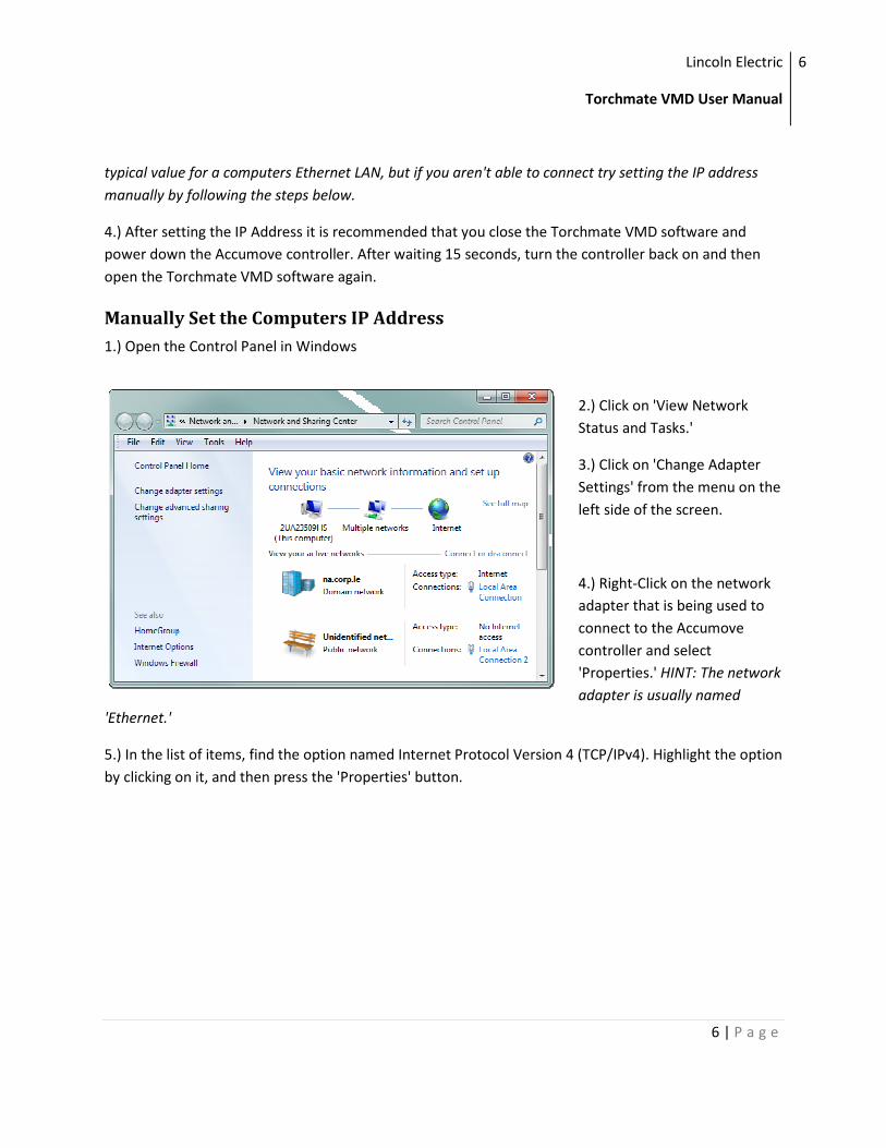
1.) Open the Control Panel in Windows
2.) Click on 'View Network
Status and Tasks.'
3.) Click on 'Change Adapter
Settings' from the menu on the
left side of the screen.
4.) Right-Click on the network
adapter that is being used to
connect to the Accumove
controller and select
'Properties.' HINT: The network
adapter is usually named
'Ethernet.'
5.) In the list of items, find the option named Internet Protocol Version 4 (TCP/IPv4). Highlight the option
by clicking on it, and then press the 'Properties' button.
Lincoln Electric
Torchmate VMD User Manual
7
7 | P a g e
6.) Make the following changes:
A.) Select 'Use the following IP Address'
B.) In the IP Address field, enter 192.168.1.6
C.) In the Subnet Mask field, enter 255.255.255.0
7.) Press 'OK' to close the properties window, and then 'OK' again to close the Ethernet window.
8.) After setting the IP Address it is recommended that you close the Torchmate VMD software and
power down the Accumove controller. After waiting 15 seconds, turn the controller back on and then
open the Torchmate VMD software again.
Lincoln Electric
Torchmate VMD User Manual
8
8 | P a g e
Windows Firewall
By default the Windows Firewall will require you to allow the Torchmate VMD software access to the
Ehternet port that it needs to communicate to the controller. You must allow access or disable the
firewall, otherwise the computer will not be able to make a connection to the controller. Other antivirus
software (i.e. Mcafee Antivirus) may block Torchmate VMD as well and should either be disabled or
configured to allow Torchmate VMD to communicate through the network port.
The easiest way to allow Torchmate VMD to access the Ethernet port is by clicking the 'Allow' button
when Windows Firewall prompts you. However, if the prompt does not appear for some reason access
can still be granted by managing the exceptions in the Windows Firewall rules. To allow access, follow
these steps:
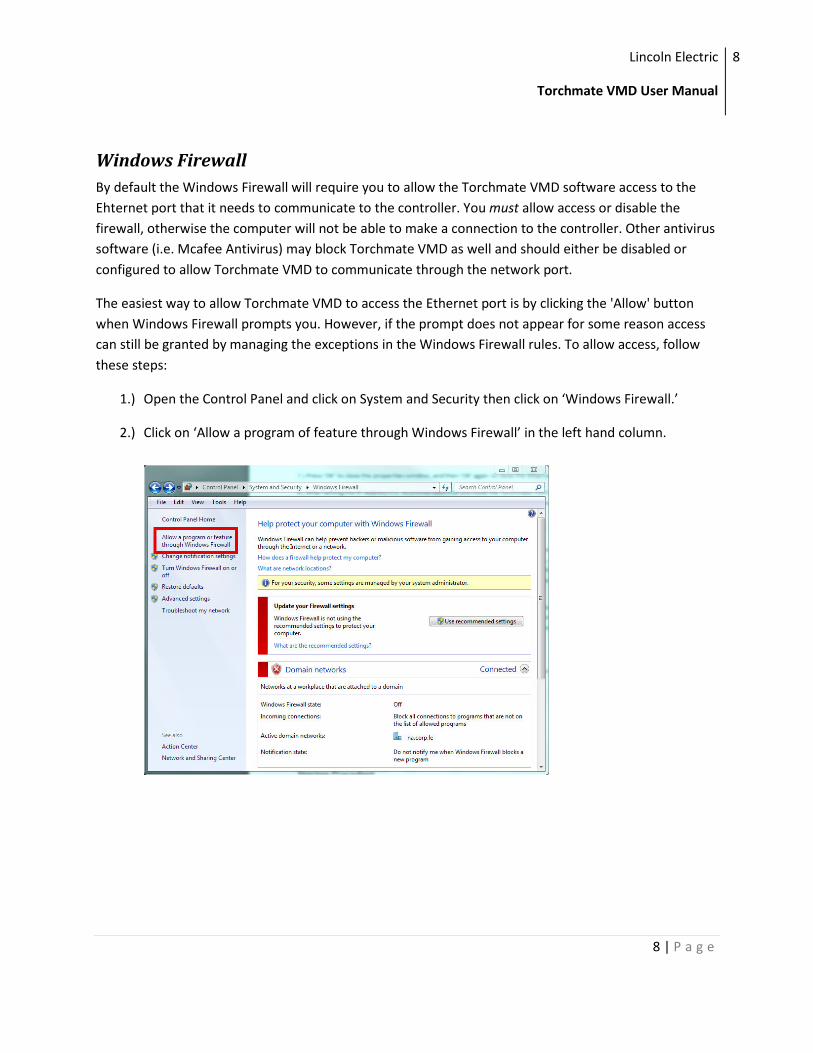
1.) Open the Control Panel and click on System and Security then click on ‘Windows Firewall.’
2.) Click on ‘Allow a program of feature through Windows Firewall’ in the left hand column.
Lincoln Electric
Torchmate VMD User Manual
9
9 | P a g e
3.) A list of allowed programs will be displayed. Click on ‘Add another program…’
4.) Finally, find ‘Torchmate Visual Machine Designer’ from the list of programs. Click ‘Add’ to allow
Torchmate VMD to communicate through the firewall.
Lincoln Electric
Torchmate VMD User Manual
10
10 | P a g e
Quickstart Guides
Startup Procedure
The first time you connect to the Accumove controller with the Torchmate VMD software you should
take a few minutes to verify proper and expected opration of the machine. This guide will lead you
through configuring your Torchmate machine, validating the motion and checking the machine inputs
and output.
Loading a Configuration File
The configuration file is a set of machine parameters that are specific to your machine. In order for the
machine to function correctly a configuration file must be loaded from the computer onto the
Accumove controller. A configuration file only needs to be loaded once; the settings are stored on the
controller, so even when the software shuts down or the controller is turned off the configuration file
should not need to be changed again. However, if your machine starts exhibiting unexpected or
inconsistent behavior it is recommended to reload the configuration file.
To load a configuration onto the controller, follow these steps:
1.) Log in as 'Admin' by clicking the 'Log On' button and selecting the Admin user (The default password
is 1234).
2.) Open the 'Machine Settings' panel by pressing the button named 'Machine Settings' on the main
screen.
3.) Press the 'Load Configuration' button.
4.) A list of all of the Torchmate machines will be presented. Select your machine from the list by clicking
on the name of the machine. When the machine is properly selected its row will be highlighted.
5.) Press 'OK' to load the configuration onto the controller. These changes will not take effect until the
machine is ‘Datumed,’ which is covered in the next step.
It is also recommended to perform a factory reset any time a new configuration file is loaded. To
perform a factory reset, press the ‘Factory Reset’ button in the Machine Settings window. After pressing
the ‘Factory Reset’ button you will need to close the Torchmate VMD software and re-open it for the
changes to take effect.
Lincoln Electric
Torchmate VMD User Manual
11
11 | P a g e
Datuming the Machine
In order for your machine to move any of the motors the controller must first have it's Datum set. We
call this 'Datuming' the machine. When the machine is Datumed two things happen: the 'machine zero'
coordinates are set to the current position of the tool, and the drives are engaged.
By design the 'machine zero' should be at the minimum limits of the machine, or the 'lower left' corner
of the machine. It is recommended that the tool be positioned at this location before Datuming the
machine. Once the machine is datumed and the machine zero is set, the Accumove controller will put
very slow speed limits when the controller detects that the tool is being moved outside of the machine
boundaries. The machine boundaries start at machine zero and extend in the positive X and Y direction
based on the machine. For example, the machine boundaries of a Torchmate 4x4 are 0-48" in X and 0
48" in Y. If the controller is commanded to move in the negative direction, or past the 48" mark, the
speed will be severely limited in order to prevent the tool from unintentionally crashing into the hard
stops of the machine.
On machines that have limit switches configured, Datuming the machine will cause the machine to
'Seek' out the machine zero. This operation automatically follows these steps when the 'Datum' button
is pressed from the main screen:
1.) Move the gantry until the home limit switch is triggered.
2.) 'Auto-Square' the following axis of the gantry.
3.) Move the tool cassette until the home limit switch is triggered.
4.) At this point, the tool has been moved to the lower left corner of the machine, and the machine zero
is set.
On machines that do not have limit switches configured the machine will not 'Seek' out the machine
zero. In this case, the current position of the tool is assigned to machine zero. You should follow these
steps to properly Datum a machine that does not have limit switches:
1.) Ensure the tool is in the lower left corner of the machine. TIP: If the tool is not in the correct location,
turn the Accumove controller off and manually move the tool to the correct location. Restart the
controller. You may also use the jog keys to jog in the negative direction but the jog speed will be
significantly reduced.
2.) Press the 'Datum' button.
Remember, after pressing the 'Datum' button, the machine will jog very slowly if you attempt to jog in
the negative direction beyond the machine zero.
Lincoln Electric
Torchmate VMD User Manual
12
12 | P a g e
Jogging the Machine
Once a configuration file has been loaded and the machine has been properly Datumed you can begin
testing the functionality of the table. In this section we will cover four different ways you can 'jog' the
tool using Torchmate VMD.
Jog Panel - Continuous Jog
In several different areas of the Torchmate VMD software you will find Jog panels. These panels are
easily identified by the bright yellow arrows for the X, Y and Z axes. The Jog Panel has three different
modes: Continuous, Incremental and Point. The 'Continuous Jog' mode is the easiest way to manually
jog the tool around the machine.
To use the continuous jog feature just click an arrow of the
axis you want to jog. The speed of the jog is determined by
where the arrow is clicked; the closer to the 'bottom' of the
arrow the slower the jog speed. Hold the mouse button
down to continue jogging; while holding the mouse button
down you may drag the mouse away from the 'bottom' of
the arrow to increase the speed of the jog. Conversely, you
may drag the mouse back towards the bottom of the arrow
to decrease the speed of the jog.
Jog Panel - Incremental Jog
Another mode of jogging from the Jog panel is by using the
incremental jog mode. To access the incremental jog mode, click the 'Incremental' tab at the top of the
Jog panel.
The incremental jog mode allows you to jog any axis by a
predefined distance. This is useful for making very small
tool movements, or to verify the positional accuracy of the
machine. To use the incremental jog feature, follow these
steps:
1.) Set the desired distance of the incremental jog. You can
do this by dragging the slider underneath the jog keys, or by
typing a distance into the text box located to the right of
the slider. While the distance of the slider is limited to 0.1",
any value can be entered into the text box. For example, if
you want to make an incremental move of 1", just type 1.0
into the text box.
Lincoln Electric
Torchmate VMD User Manual
13
13 | P a g e
2.) Press the jog key that corresponds to the axis and direction of which you intend to move the tool.
After pressing the jog key, the tool will move by the specified amount. You can continue pressing the jog
key to make more incremental moves.
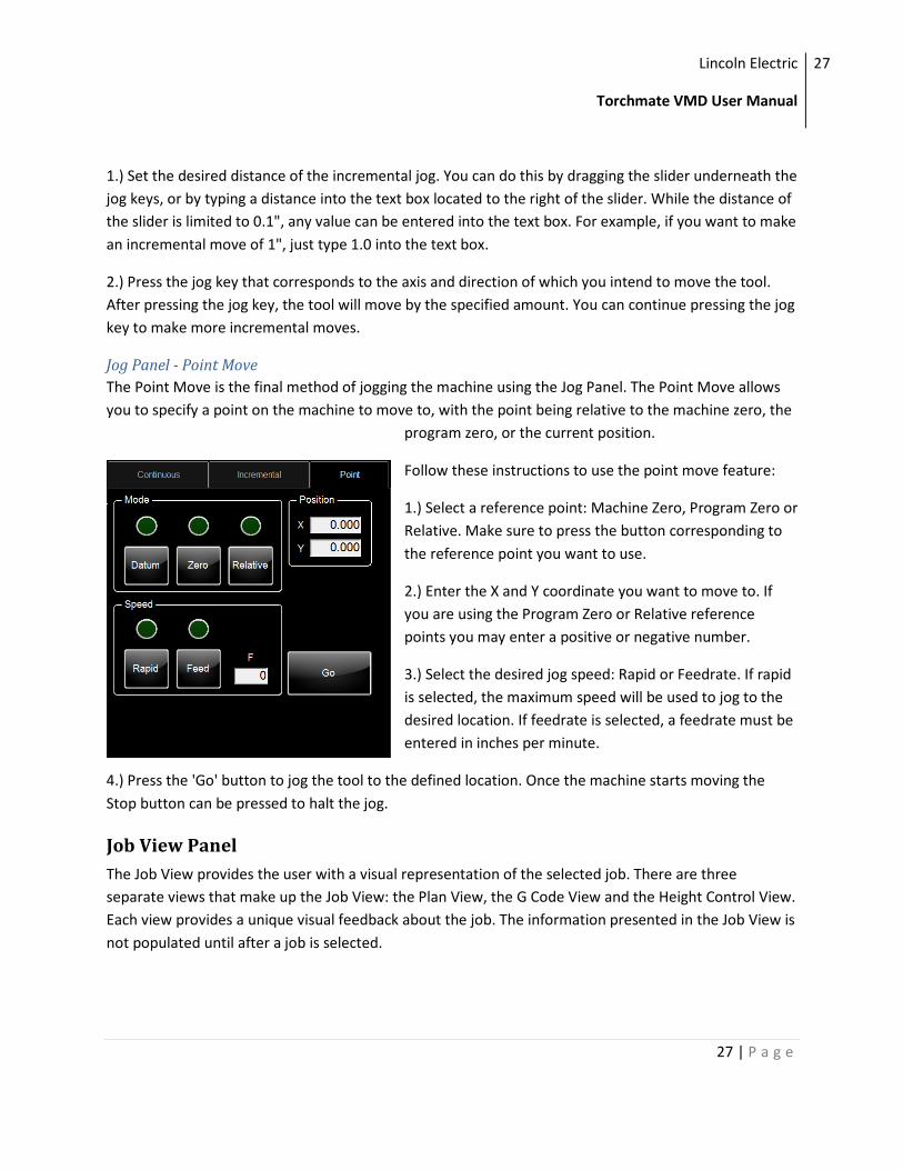
Jog Panel - Point Move
The Point Move is the final method of jogging the machine using the Jog Panel. The Point Move allows
you to specify a point on the machine to move to, with the point being relative to the machine zero, the
program zero, or the current position.
Follow these instructions to use the point move feature:
1.) Select a reference point: Machine Zero, Program Zero or
Relative. Make sure to press the button corresponding to
the reference point you want to use.
2.) Enter the X and Y coordinate you want to move to. If
you are using the Program Zero or Relative reference
points you may enter a positive or negative number.
3.) Select the desired jog speed: Rapid or Feedrate. If rapid
is selected, the maximum speed will be used to jog to the
desired location. If feedrate is selected, a feedrate must be
entered in inches per minute.
4.) Press the 'Go' button to jog the tool to the defined location.
Move To Here
Finally, you can jog to any point on the machine quickly by using the 'Move to Here' feature. This feature
allows you to click on the 'Job View' window and move to the position that corresponds to the location
of your mouse.
The Job View window has a thin blue outline which represents
the boundaries of your machine. If you move your mouse to a
position within the boundaries, you can quickly tell the
Accumove controller to jog the tool to that position. Follow these
steps to use the 'Move to Here' feature:
1.) In the Plan View window of the main screen, right-click on a
point inside the thin blue outline that represents your machine.
2.) Select the 'Move To Here' option from the pop up menu.
Lincoln Electric
Torchmate VMD User Manual
14
14 | P a g e
3.) The machine will automatically move the X and Y axis to the location that corresponds to your mouse
position.
Check the Breakaway Sensor
The torch breakaway is a standard feature of Torchmate machines. The breakaway will help prevent
your plasma torch from being damaged in the event that the torch collides with an object while
executing a part program. The breakaway sensor works by sending a signal to the Accumove controller
when the torch breaks away from the torch holder; when the controller receives this signal it halts the
machine and shuts down the plasma tool.
Follow these steps to ensure that the breakaway sensor is functioning properly:
1.) Set the torch into the torch holder so that it is being held in place by the magnets. When properly
placed the torch should not rock within the holder. (Note: If your machine does not have a breakaway,
skip steps 1 and 2)
2.) Verify that the 'Breakaway Detected' lights in the Dashboard of the main screen have the text
'Closed.' These indicators should be gray in color.
3.) Manually break the torch off of the torch holder by pulling on the torch.
4.) Verify that the 'Breakaway Detected' lights turn yellow and have the text 'Open.'
If either of these tests fails please see the troubleshooting guide for steps on how to resolve the issue.
Check the Ohmic Cap Detected Sensor
The ohmic cap is a recommended accessory for customers using plasma cutters with an Accumove
controller. An ohmic cap is a special type of retaining cap consumable for a plasma machine torch; the
cap allows the controller to determine when the torch comes in contact with the material.
If you purchased an ohmic cap with your machine torch you should test to ensure that the detection
signal is working before running a job. Be sure to follow the Accumove Wiring Guide to connect your
ohmic cap to the Accumove controller before performing this test. To test your ohmic cap follow these
steps:
1.) Place a piece of material onto the table and ensure that the material is properly grounded to the
machine. The material must be able to conduct electricity in order for the ohmic cap to work.
2.) Using the continuous jog keys, position the torch over the material.
3.) Jog the Z axis down slowly until the tip of the torch is just touching the material.
Lincoln Electric
Torchmate VMD User Manual
15
15 | P a g e
4.) Verify that the ‘Ohmic Cap Detected’ light has turned on in the bottom right corner of the main
screen of the VMD software.
If this test fails please see the troubleshooting guide for steps on how to resolve the issue.
Running a Job
Once the machine has been configured and you have tested the inputs and outputs to your satisfaction
you can begin running jobs. You should only need to configure your machine and test the I/O when you
first set up your machine, or if there are any significant changes to the setup of your machine (i.e.
adding or removing tools or accessories), although there are rare instances where a controller
malfunction may require you to reload the machines configuration.
In Torchmate VMD, a job is a g-code file. G-code files are text files that contain valid Accumove G-codes
and typically the filename ends with the letters .gm. A list of all of the G-codes accepted by the
Accumove controller is located in Appendix A: Accumove G&M Code Programs.
There are two main methods of creating a job: they can be generated from an external CAD program like
Torchmate CAD using a post-processor, or they can be created directly in Torchmate VMD by using the
shape library. Read the Torchmate CAD/CAM documentation to learn how to output machine code for
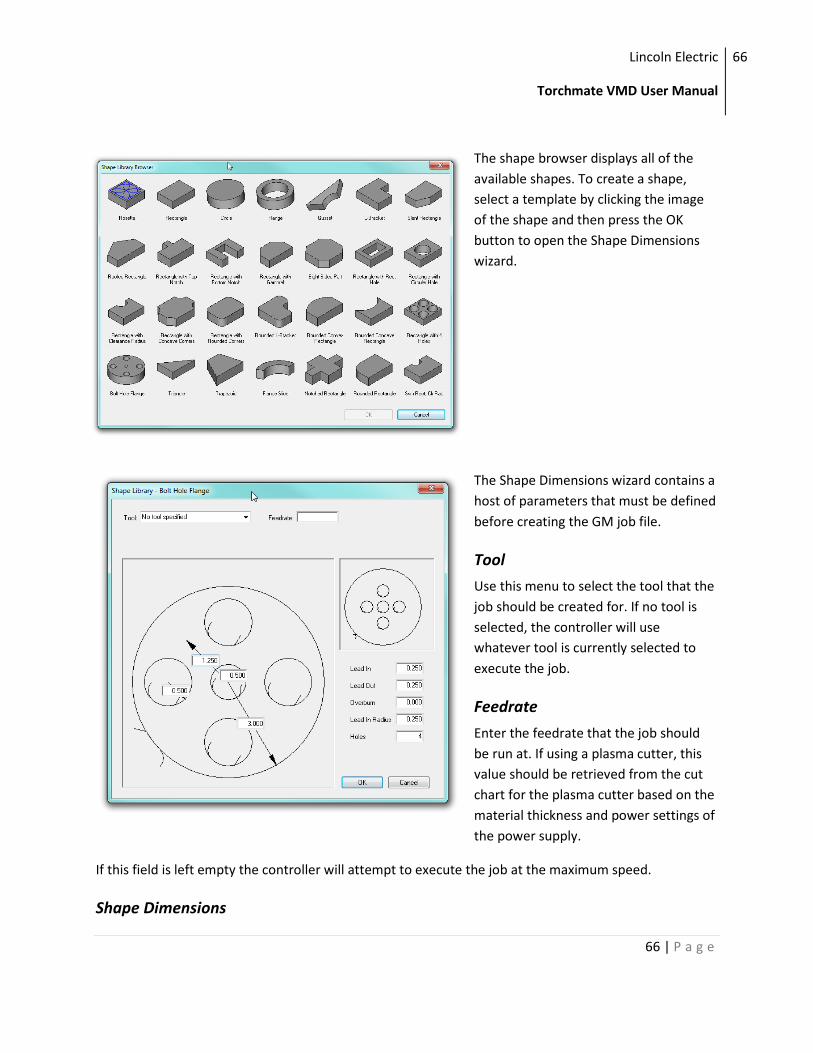
your CAD Design. Instructions on how to use the shape library to create jobs are located in the Shape
Library section of this manual.
For this quickstart guide we will use one of the jobs that is included with the installation of the
Torchmate VMD software. This guide will also assume that you are using an ohmic cap; if you are not
using an ohmic cap please use the ‘Running a Job without Ohmic Sensing’ guide. This quickstart guide
will be split into two main sections: preparing the job and executing the job.
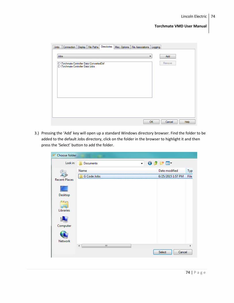
Preparing a Job
1.) From the main screen, press the ‘Select Job’ button located in the upper left hand corner of the
screen.
2.) Torchmate VMD will open up a job selection screen. By default this screen is configured to show
all of the jobs located in the ‘Jobs’ folder of the Torchmate VMD directory. Also, it will only
display the .gm files that are in the directory. For this guide, double click on the ‘Simple Cut
Test– 70ipm.gm’ file to cut out a simple part. You can also click the ‘Browse’ button to find gm
files that are located in separate locations on your computer. Remember, you should always
datum the machine before you can load a job.
Once the job has been selected you will be taken back to the main screen. A couple of changes
take place:
Lincoln Electric
Torchmate VMD User Manual
16
16 | P a g e
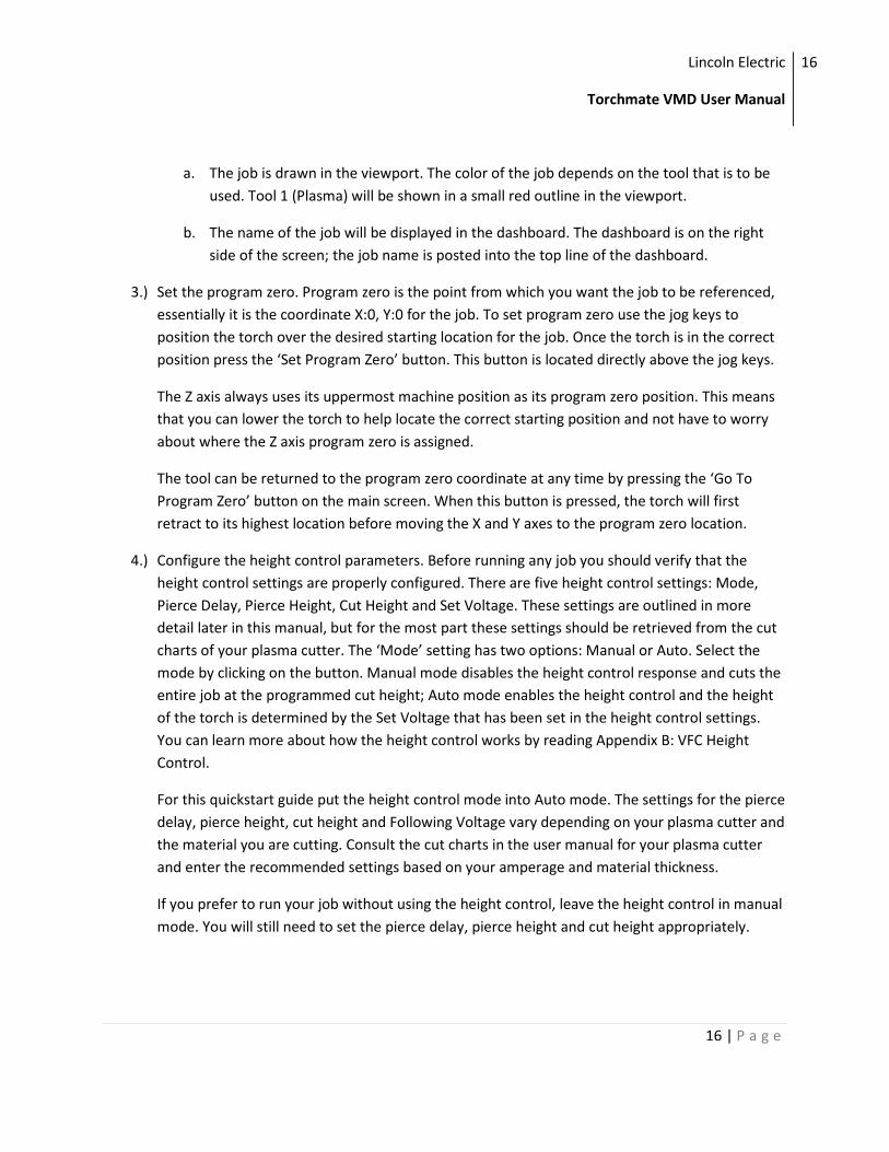
a. The job is drawn in the viewport. The color of the job depends on the tool that is to be
used. Tool 1 (Plasma) will be shown in a small red outline in the viewport.
b. The name of the job will be displayed in the dashboard. The dashboard is on the right
side of the screen; the job name is posted into the top line of the dashboard.
3.) Set the program zero. Program zero is the point from which you want the job to be referenced,
essentially it is the coordinate X:0, Y:0 for the job. To set program zero use the jog keys to
position the torch over the desired starting location for the job. Once the torch is in the correct
position press the ‘Set Program Zero’ button. This button is located directly above the jog keys.
The Z axis always uses its uppermost machine position as its program zero position. This means
that you can lower the torch to help locate the correct starting position and not have to worry
about where the Z axis program zero is assigned.
The tool can be returned to the program zero coordinate at any time by pressing the ‘Go To
Program Zero’ button on the main screen. When this button is pressed, the torch will first
retract to its highest location before moving the X and Y axes to the program zero location.
4.) Configure the height control parameters. Before running any job you should verify that the
height control settings are properly configured. There are five height control settings: Mode,
Pierce Delay, Pierce Height, Cut Height and Set Voltage. These settings are outlined in more
detail later in this manual, but for the most part these settings should be retrieved from the cut
charts of your plasma cutter. The ‘Mode’ setting has two options: Manual or Auto. Select the
mode by clicking on the button. Manual mode disables the height control response and cuts the
entire job at the programmed cut height; Auto mode enables the height control and the height
of the torch is determined by the Set Voltage that has been set in the height control settings.
You can learn more about how the height control works by reading Appendix B: VFC Height
Control.
For this quickstart guide put the height control mode into Auto mode. The settings for the pierce
delay, pierce height, cut height and Following Voltage vary depending on your plasma cutter and
the material you are cutting. Consult the cut charts in the user manual for your plasma cutter
and enter the recommended settings based on your amperage and material thickness.
If you prefer to run your job without using the height control, leave the height control in manual
mode. You will still need to set the pierce delay, pierce height and cut height appropriately.
Lincoln Electric
Torchmate VMD User Manual
17
17 | P a g e
Executing a Job
1.) Visually verify that there is enough room on the plate to run the job without the tool colliding
into the machine limits. Jog the Z axis all the way to the top of the slide and press the ‘Reset Z
Position’ button; this ensures that the Z axis is using the correct reference point for height
control motions. Once you have checked this, press the green ‘Run Job’ button located beneath
the jog keys.
After setting the program zero for your job and configuring the height control parameters the
machine is ready to run the job. Use the jog keys to lower the torch so that it is closer to the
material height; leaving about 1 inch between the tip of the torch and the top of the material is
a good rule of thumb.
Check that power has been applied to the plasma cutter. Make sure that the ‘Run Mode’ button
is set to ‘Active Run,’ the run mode button is located just above the jog keys. The only options
for the run mode are ‘Dry Run’ and ‘Active Run.’ A dry run allows you to run a job without
actually firing the torch, while the active run will turn the tool on to cut out the part.
If you get an error immediately after pressing the ‘Run Job’ button view the troubleshooting
guide at the end of this manual for help in resolving the issue.
2.) After pressing the ‘Run Job’ button the controller will begin executing an IHS Sequence (Initial
Height Sense) by lowering the torch slowly until the ohmic cap detects the material. (If you’re
not using an ohmic cap, STOP! Read the next quickstart guide on running a job without ohmic
sensing.) After the ohmic cap detects the material the torch will rise up to the pierce height and
fire the plasma, before lowering the torch to the cut height and running the job.
If the Z axis rapidly moves to a predetermined height without ‘touching off’ on the material it
likely means that ohmic sensing has been disabled. Stop the job and open the ‘Job Setup’ screen
and enable ohmic sensing. Make sure to reset the job by pressing the ‘Reset’ button before
trying again.
To learn more about how the IHS Sequence works, read the IHS Sequence section in the Job
Setup Panel chapter of this manual.
If you experience an error during the IHS sequence consult the troubleshooting guide for tips on
how to resolve the issue.
3.) At any point a running job can be stopped by pressing the red 'Stop' button. A 'Stop' button is
located on every panel of the Torchmate VMD software. If you are currently on the main run
Lincoln Electric
Torchmate VMD User Manual
18
18 | P a g e
screen the job can also be stopped by pressing the 'spacebar' key one the keyboard.
If the Stop button is not pressed the job will run to completion and will only stop if an error
occurs during execution. Possible errors include if the torch breaks away causing a breakaway
fault, the machine tries to travel beyond its machine limits causing an overtravel error, or an
error happens during an HIS sequence causing an HIS Failure error.
Read more about how Torchmate VMD provides user feedback during job execution in the 'Run
Panel' section of this manual.
Running a Job without Ohmic Sensing
If the machine doesn’t have an ohmic cap installed there is still an easy way to run jobs with a plasma
cutter. It is recommended to read the previous quickstart guide ‘Running a Job’ before performing this
quickstart guide in order to gain familiarity with some of the required steps to run a job.
To run a job without the ohmic cap you will first need to perform steps 1-4 from the ‘Preparing a Job’
section of the previous guide. Next you will need to disable the ohmic sensing and set the material
thickness to run the job without the ohmic sensing. Follow these steps to configure the appropriate
settings:
1.) Disable Ohmic Sensing
a. Open the ‘Job Setup’ screen by clicking the button in the upper left side of the main
screen. By default, the ‘Ohmic Sensing’ feature will be enabled. The button indicates if
the feature is On or Off. Click the button to turn Ohmic Sensing Off.
2.) Set the material thickness
a. When running Torchmate VMD with ohmic sensing disabled, the ‘Material Thickness’ is
actually a misnomer. Rather than representing the actual thickness of the material it
actually represents the Z Axis machine position that correlates to where the torch
touches the material.
To set the material thickness properly use the jog buttons to lower the torch until the
tip of the torch is just touching the top of the material. Once the torch is touching the
material press the ‘Set’ button under the ‘Material Thickness’ label. Torchmate VMD will
capture the correct material thickness to be used when Ohmic sensing is disabled.
TIP: Before lowering the torch to the material, jog the Z axis all the way up to the top of
Lincoln Electric
Torchmate VMD User Manual
19
19 | P a g e
the slide and press the ‘Reset Z Position’ button on the main screen. This will ensure that
the proper coordinates are used when capturing the Z axis position.
After disabling ohmic sensing and setting the material thickness the job can be run normally; follow the
Running a Job Guide for a detailed walkthrough on loading and running the job.. When running a job
with ohmic sensing disabled it is recommended to perform a ‘dry run’ of the job before running an
active run. This will help to ensure that the material thickness has been set correctly without risking ‘air-
firing’ the plasma cutter.
Torchmate VMD Panels
Each screen in Torchmate VMD is called a Panel. There are six main Panels in the Torchmate VMD
software. In this section each of the Panels and their associated options will be explained in detail.
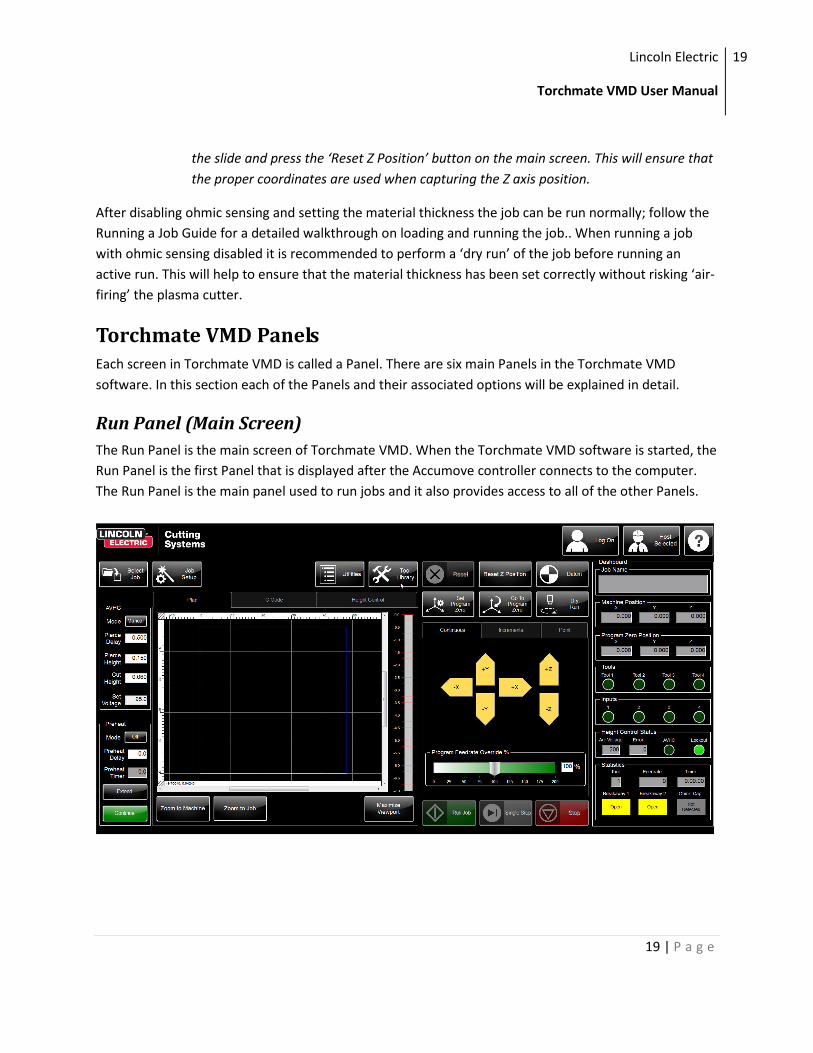
Run Panel (Main Screen)
The Run Panel is the main screen of Torchmate VMD. When the Torchmate VMD software is started, the
Run Panel is the first Panel that is displayed after the Accumove controller connects to the computer.
The Run Panel is the main panel used to run jobs and it also provides access to all of the other Panels.
Lincoln Electric
Torchmate VMD User Manual
20
20 | P a g e
Log On Button
The Log On button opens the log on screen. From the log on screen a
user can be selected from which to run the machine. Each user has
different access rights in the Torchmate VMD Software.
Operator
The operator user is limited to opening, configuring and running
jobs. The operator user does not have access to modify system or
machine settings.
Admin (Password Protected)
The admin user has all of the access that the operator has. In
addition the admin user can access the Machine Settings panel
which allows them to load a machine configuration and change basic
I/O behavior. They can also change some system settings for the
VMD software. The Admin user is password protected. The default
password for the Admin user is 1234.
Tech Support (Password Protected)
The Tech Support user has access to special diagnostic tools used by
the Torchmate Technical Support team. Your Technical Support
representative will provide you with this password while assisting
you on the phone if the need arises.
Select Job Button
The Select Job button opens the select job browser. From this screen a
job file may be chosen.
Lincoln Electric
Torchmate VMD User Manual
21
21 | P a g e
Select a Job Dialogue
By default the Select Job browser will display all
of the g code files that are in the default Jobs
folder (C:\Torchmate Controller Data\Jobs).
Double click on a filename to select a job.
Alternatively you may click on a filename to
highlight the job and see a preview in the preview
window. Then press the ‘OK’ button to select the
job.
The ‘Browse’ button allows the user to browse
through additional directories on the computer
to select a job.
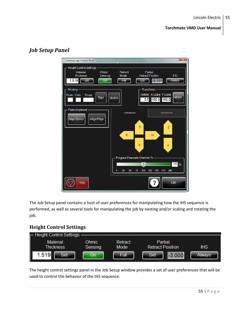
Job Setup Button
The Job Setup button will open up the Job Setup Panel. Read more
about the Job Setup Panel in the Job Setup Panel section in the
manual.
Machine Settings Button
The Machine Settings button opens the Machine Settings Panel.
Read more about this panel in the Machine Settings Panel section
below.
This button only appears when logging in as the Admin user.
Utilities Button
The Utilities button opens the Utility selection panel. Read more
about this panel and the available utilities in the Utilities Panel
section of this manual.
Lincoln Electric
Torchmate VMD User Manual
22
22 | P a g e
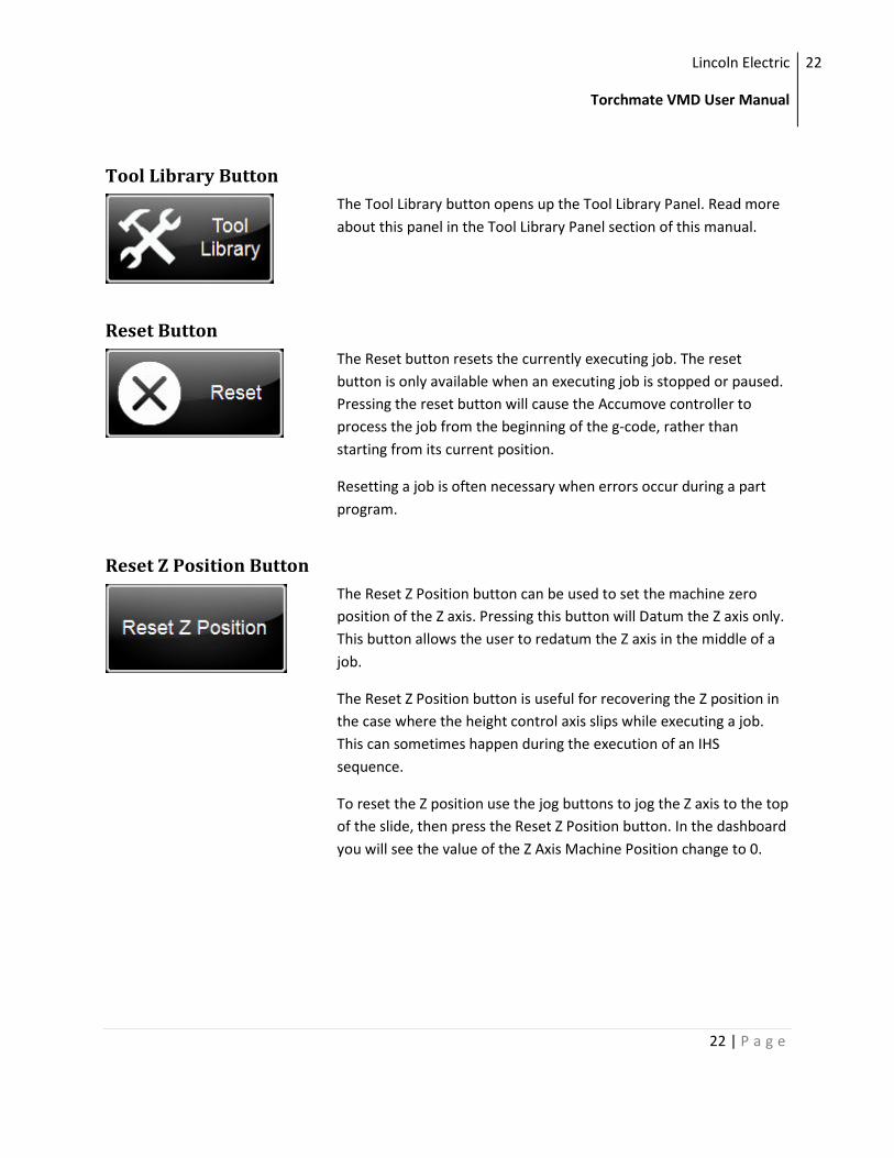
Tool Library Button
The Tool Library button opens up the Tool Library Panel. Read more
about this panel in the Tool Library Panel section of this manual.
Reset Button
The Reset button resets the currently executing job. The reset
button is only available when an executing job is stopped or paused.
Pressing the reset button will cause the Accumove controller to
process the job from the beginning of the g-code, rather than
starting from its current position.
Resetting a job is often necessary when errors occur during a part
program.
Reset Z Position Button
The Reset Z Position button can be used to set the machine zero
position of the Z axis. Pressing this button will Datum the Z axis only.
This button allows the user to redatum the Z axis in the middle of a
job.
The Reset Z Position button is useful for recovering the Z position in
the case where the height control axis slips while executing a job.
This can sometimes happen during the execution of an IHS
sequence.
To reset the Z position use the jog buttons to jog the Z axis to the top
of the slide, then press the Reset Z Position button. In the dashboard
you will see the value of the Z Axis Machine Position change to 0.
Lincoln Electric
Torchmate VMD User Manual
23
23 | P a g e
Datum Button
The Datum button is used to set the Machine Zero position for all
axes. Because the Accumove controller will not move without the
Machine Zero position being set, none of the motors will move until
after the Datum button is pressed.
The behavior of the Datum button varies based on the Homing
settings of the machine configuration. If ‘Seek Home’ is enabled in
the homing settings, pressing the Datum button will cause the
machine to start moving the machine towards the machines limit
switches. If ‘Seek Home’ is disabled pressing Datum will only engage
the motors and set the current position to the Machine Zero
position.
TIP: In a machines default configuration, the machine zero
coordinate is the minimum travel distance for the machine.
Attempting to jog beyond the minimum travel limit will result in
extremely slow jog speeds! In this case, manually jog the machine to
the true machine zero (lower, left corner of the machine) and then
press the Datum button again to reset the machine coordinates.
This behavior can be avoided by returning the tool to the machine
zero position before powering the Accumove controller off. If the
machine is not located at the machine zero location, consider
manually pushing the gantry and tool to the machine zero before
powering up the Accumove controller.
Set Program Zero Button
The Set Program Zero button is used to set the program zero
location for a job. This is the position that will be used as the X:0, Y:0
location during job execution. By default this position is set to the
machine zero position.
Typically the program zero location is chosen to be the start point of
the job. In general, the usage of this feature requires using the job
keys to move the torch (or desired tool) to the point from which the
job should be started. Once the tool is in the correct location, press
Lincoln Electric
Torchmate VMD User Manual
24
24 | P a g e
the Set Program Zero button to store the location.
The Set Program Zero button can only be used when a job is not in
progress; this includes when a job is stopped. A job must be in the
Reset state for the button to actually set the program zero location.
Go To Program Zero Button
The Go To Program Zero button causes the machine to move the
tool to the program zero location. When this button is pressed, the Z
axis will first retract to the machine zero height, then the X and Y
axes will move to the program zero location.
This button can only be used when a job is not currently being
executed. However, if a job is paused or stopped, this button can be
used to quickly move the tool back to the origin of the job.
Run Mode Button
The Run Mode button is used to change the run mode between
Active Run and Dry Run. The current mode is displayed on the button
itself.
Active Run
Active run is the run mode used to cut a part. In run mode, the job
will execute normally, turning the tool on and off when the
corresponding M codes are encountered (M64 and M65).
Dry Run
Dry run is the run mode used to test the execution of a part. In dry
run mode the job will execute without turning the tool on or off by
ignoring the corresponding M codes. Dry run is useful when learning
how to use the software, or to validate a g code before cutting
material. In dry run mode, the ‘OK To Move’ signal will also be
ingored.
Lincoln Electric
Torchmate VMD User Manual
25
25 | P a g e
Run Job Button
The Run Job button is used to start a job. Pressing this button will
cause the job to start cutting immediately, so be sure that the job is
completely prepared before pressing the Run Job button.
The Run Job button is only available after a job has been selected.
The Run Job button can also be used to resume a job after an error
or after a stop.
When a job is resumed it will start from the position at which it was
previously stopped. So if the tool has been jogged from its position
during a pause, pressing the Run Job button will cause the tool to
move back to the previous position. If the job was stopped during a
cut, then resuming the job will start an IHS sequence before turning
the tool on.
Single Step Button
The Single Step button will cause the Accumove controller to execute
a single g code line from the current job. This button is available in
either Active Run or Dry Run mode, which means that it can be used
to skip features in the job. It is also possible to ‘search’ to a specific
part of a job by using Dry Run mode, single stepping to the desired
start location, and then changing to Active Run before running the
job.
Stop Button
The Stop button will cause the Accumove controller to stop
executing a job. The Stop button is only active when a job is running,
and will cause the controller to come to a controlled stop before
turning the tool off (if it’s active).
When a job is stopped, its location is saved. This way the controller
can resume the job at the correct location. After stopping a job the
user is free to jog the tool away from the stopped location to allow
for inspecting the progress of the job or the quality of the cut.
To resume a job after stopping it, press the Run Job button. If it is
Lincoln Electric
Torchmate VMD User Manual
26
26 | P a g e
desired to start the job from the beginning of the g code first press
the Reset button before pressing the Run Job button.
For safety reasons a Stop button is located on every Panel in the
Torchmate VMD software. Any stop button may be pressed to stop
running the job.
Jog Panel
The jog panel can be used to manually move the tool around the machine. Jog panels can be found in
several different areas of the Torchmate VMD software. These panels are easily identified by the bright
yellow arrows for the X, Y and Z axes. The Jog Panel has three different modes: Continuous, Incremental
and Point. Each type of jog can be access by clicking on the appropriate tab.
Jog Panel - Continuous Jog
The 'Continuous Jog' mode is the easiest way to manually jog
the tool around the machine. To use the continuous jog
feature just click an arrow of the axis you want to jog. The
speed of the jog is determined by where the arrow is clicked;
the closer to the 'bottom' of the arrow the slower the jog
speed. Hold the mouse button down to continue jogging;
while holding the mouse button down you may drag the
mouse away from the 'bottom' of the arrow to increase the
speed of the jog. Conversely, you may drag the mouse back
towards the bottom of the arrow to decrease the speed of
the jog.
Jog Panel - Incremental Jog
Another mode of jogging from the Jog panel is by using the
incremental jog mode. To access the incremental jog mode,
click the 'Incremental' tab at the top of the Jog panel.
The incremental jog mode allows you to jog any axis by a
predefined distance. This is useful for making very small
tool movements, or to verify the positional accuracy of the
machine. To use the incremental jog feature, follow these
steps:
Lincoln Electric
Torchmate VMD User Manual
27
27 | P a g e
1.) Set the desired distance of the incremental jog. You can do this by dragging the slider underneath the
jog keys, or by typing a distance into the text box located to the right of the slider. While the distance of
the slider is limited to 0.1", any value can be entered into the text box. For example, if you want to make
an incremental move of 1", just type 1.0 into the text box.
2.) Press the jog key that corresponds to the axis and direction of which you intend to move the tool.
After pressing the jog key, the tool will move by the specified amount. You can continue pressing the jog
key to make more incremental moves.
Jog Panel - Point Move
The Point Move is the final method of jogging the machine using the Jog Panel. The Point Move allows
you to specify a point on the machine to move to, with the point being relative to the machine zero, the
program zero, or the current position.
Follow these instructions to use the point move feature:
1.) Select a reference point: Machine Zero, Program Zero or
Relative. Make sure to press the button corresponding to
the reference point you want to use.
2.) Enter the X and Y coordinate you want to move to. If
you are using the Program Zero or Relative reference
points you may enter a positive or negative number.
3.) Select the desired jog speed: Rapid or Feedrate. If rapid
is selected, the maximum speed will be used to jog to the
desired location. If feedrate is selected, a feedrate must be
entered in inches per minute.
4.) Press the 'Go' button to jog the tool to the defined location. Once the machine starts moving the
Stop button can be pressed to halt the jog.
Job View Panel
The Job View provides the user with a visual representation of the selected job. There are three
separate views that make up the Job View: the Plan View, the G Code View and the Height Control View.
Each view provides a unique visual feedback about the job. The information presented in the Job View is
not populated until after a job is selected.
Lincoln Electric
Torchmate VMD User Manual
28
28 | P a g e
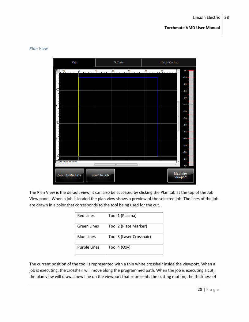
Plan View
The Plan View is the default view; it can also be accessed by clicking the Plan tab at the top of the Job
View panel. When a job is loaded the plan view shows a preview of the selected job. The lines of the job
are drawn in a color that corresponds to the tool being used for the cut.
Red Lines Tool 1 (Plasma)
Green Lines Tool 2 (Plate Marker)
Blue Lines Tool 3 (Laser Crosshair)
Purple Lines Tool 4 (Oxy)
The current position of the tool is represented with a thin white crosshair inside the viewport. When a
job is executing, the crosshair will move along the programmed path. When the job is executing a cut,
the plan view will draw a new line on the viewport that represents the cutting motion; the thickness of
Lincoln Electric
Torchmate VMD User Manual
29
29 | P a g e
this line will reflect the kerf of the selected line. If the value of the kerf is 0 then a very thin line will still
be drawn on top of the job preview.
The plan view contains an outline of the machine boundaries; the boundary is drawn in small blue line.
The size of the machine boundaries will change based on the machine configuration that has been
loaded.
The grid in the plan view changes its scale automatically based on the current zoom level. The scale can
be determined by observing the ruler along the top and left sides of the viewport.
There are three ways to zoom in and out of the plan view: the Zoom buttons, the mouse shortcuts and
the Right-Click menu.
Zoom Buttons
The Zoom to Job button will reset the plan view so that it fits the size
of the currently selected job. This is a good way to reset the view
after zooming in and out of the plan view.
When a job is first loaded it will automatically zoom to the job.
The Zoom To Machine button will reset the plan view so that it fits
the extents of the machine. This is a good way to see how the job is
oriented on the machine, and it is also useful to see where the
controller thinks the tool is as it relates to the machine boundaries.
Mouse Shortcuts
There are two mouse shortcuts that allow the user to zoom in and out of the job: clicking and dragging,
and using the scroll wheel on the mouse.
To zoom by clicking and dragging, click and hold the left mouse button, and then drag a square box
around the area to be zoomed to. Once the mouse button is released the plan view will reset to the
selected area.
To zoom in and out of the plan view using the scroll wheel on the mouse, hold the Control key on the
keyboard and the place the mouse key over the spot on the plan view that should be zoomed into or out
of. Scroll the wheel while holding the Control key down to zoom in and out of the view.
Lincoln Electric
Torchmate VMD User Manual
30
30 | P a g e
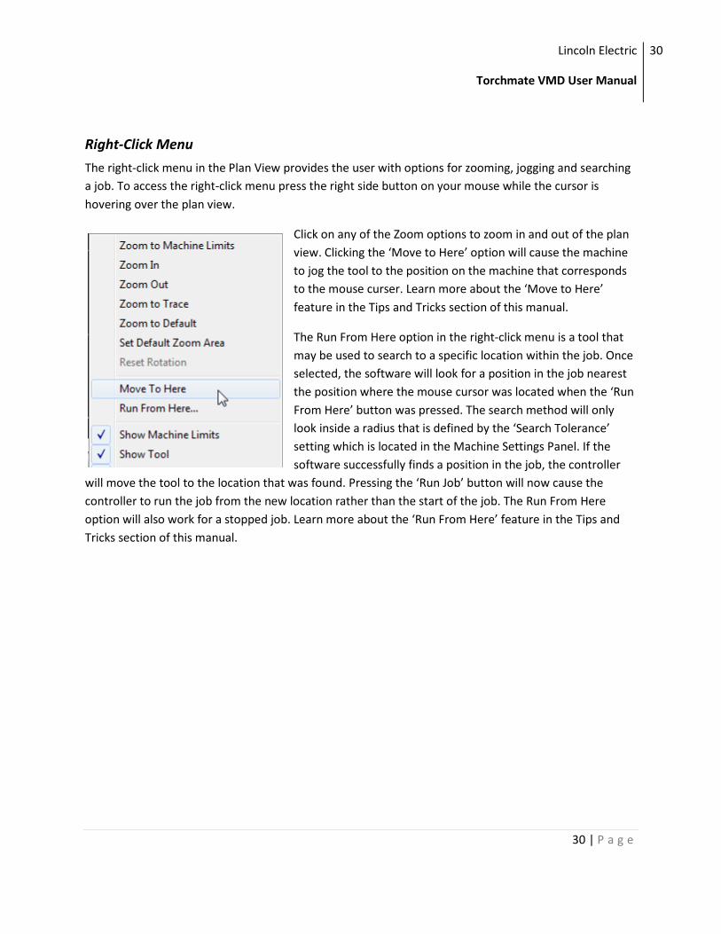
Right-Click Menu
The right-click menu in the Plan View provides the user with options for zooming, jogging and searching
a job. To access the right-click menu press the right side button on your mouse while the cursor is
hovering over the plan view.
Click on any of the Zoom options to zoom in and out of the plan
view. Clicking the ‘Move to Here’ option will cause the machine
to jog the tool to the position on the machine that corresponds
to the mouse curser. Learn more about the ‘Move to Here’
feature in the Tips and Tricks section of this manual.
The Run From Here option in the right-click menu is a tool that
may be used to search to a specific location within the job. Once
selected, the software will look for a position in the job nearest
the position where the mouse cursor was located when the ‘Run
From Here’ button was pressed. The search method will only
look inside a radius that is defined by the ‘Search Tolerance’
setting which is located in the Machine Settings Panel. If the
software successfully finds a position in the job, the controller
will move the tool to the location that was found. Pressing the ‘Run Job’ button will now cause the
controller to run the job from the new location rather than the start of the job. The Run From Here
option will also work for a stopped job. Learn more about the ‘Run From Here’ feature in the Tips and
Tricks section of this manual.
Lincoln Electric
Torchmate VMD User Manual
31
31 | P a g e
G Code View
The G Code view is a text viewer which shows the file contents of the selected job. The g code view can
be accessed by clicking on the G Code tab at the top of the Job View panel. Since a g code file is just a
text file that only contains valid g codes, the g code view is essentially just a text viewer. When a job is
running the currently executed g code will be highlighted in blue.
The g code can be manually edited from the g code view by pressing the ‘Edit GM’ button at the bottom
of the panel. Pressing this button will open a text editor in a new window. The text editor will open with
the currently selected job open inside. The g code can be edited and saved directly inside this text
editor. After saving a g code, the selected job in Torchmate VMD will automatically be updated; that is,
unless the job is already being executed. In this case the job will need to be reloaded by selecting the job
again.
Lincoln Electric
Torchmate VMD User Manual
32
32 | P a g e
Height Control View
The Height Control view is a graph which displays the position of the Z axis. The height control view can
be accessed by clicking the Height Control tab at the top of the Job View panel. The height control view
is a good tool for diagnosing and observing the behavior of IHS sequences as well as how the AVHC is
reacting to the material.
By default, the height control graph is turned off. The Trace On/Off button is used to turn the trace on or
off. When the button reads ‘Trace On’ and is colored green the trace is turned on. Once the graph has
been turned on the height control readings will be plotted with a red line on the height control graph.
The graph will store a history of the height values. To view the history the graph must be paused. Use
the Trace Pause/Resume button to pause the graph. Once the graph is paused, use the scroll bars at the
bottom of the graph to view the historical information. Don’t forget to press the Pause/Resume button
again to start recording data again.
Lincoln Electric
Torchmate VMD User Manual
33
33 | P a g e
The graph can be zoomed in/out while it is paused. To zoom on a paused graph just click and drag a
square around the area to be zoomed to. To zoom out, while the graph is paused, right-click on the
graph and select Zoom to Default.
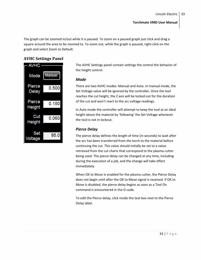
AVHC Settings Panel
The AVHC Settings panel contain settings the control the behavior of
the height control.
Mode
There are two AVHC modes: Manual and Auto. In manual mode, the
Set Voltage value will be ignored by the controller. Once the tool
reaches the cut height, the Z axis will be locked out for the duration
of the cut and won’t react to the arc voltage readings.
In Auto mode the controller will attempt to keep the tool at an ideal
height above the material by ‘following’ the Set Voltage whenever
the tool is not in lockout.
Pierce Delay
The pierce delay defines the length of time (in seconds) to wait after
the arc has been transferred from the torch to the material before
continuing the cut. This value should initially be set to a value
retrieved from the cut charts that correspond to the plasma cutter
being used. The pierce delay can be changed at any time, including
during the execution of a job, and the change will take effect
immediately.
When OK to Move is enabled for the plasma cutter, the Pierce Delay
does not begin until after the OK to Move signal is received. If OK to
Move is disabled, the pierce delay begins as soon as a Tool On
command is encountered in the G code.
To edit the Pierce delay, click inside the text box next to the Pierce
Delay label.
Lincoln Electric
Torchmate VMD User Manual
34
34 | P a g e
Pierce Height
The pierce height defines the distance (in inches) above the material
where the tool should move before activating the tool. This value
should initially be set to a value retrieved from the cut charts that
correspond to the plasma cutter being used. The pierce height can
be changed at any time, including during the execution of a job, and
the change will take effect immediately.
After moving to the pierce height, the tool will turn on, wait for the
pierce delay, and then move to the Cut Height before starting to
execute the job. The pierce height is only used if the current tool has
the ‘On Z’ option enabled in the Tool Library.
Cut Height
The Cut Height defines the distance above the material where the
tool should be while running the job. If the AVHC is in Auto mode,
the cut height will change during the cut as the controller reacts to
different arc voltages; however if the AVHC is in manual mode the
tool will be held at the distance defined by the Cut Height for the
duration of the cut. This value should initially be set to a value
retrieved from the cut charts that correspond to the plasma cutter
being used. The cut height can be changed at any time, including
during the execution of a job, and the change will take effect
immediately.
After moving to the pierce height, the tool will turn on, wait for the
pierce delay, and then move to the Cut Height before starting to
execute the job. The cut height is only used if the current tool has
the ‘On Z’ option enabled in the Too Library.
Lincoln Electric
Torchmate VMD User Manual
35
35 | P a g e
Set Voltage
The Set Voltage defines the ideal arc voltage that should be
maintained while plasma cutting to achieve the desired cut height.
This value should initially be set to a value retrieved from the cut
charts that correspond to the plasma cutter being used. The set
voltage can be changed at any time, including during the execution
of a job, and the change will take effect immediately.
The set voltage is only used when the AVHC is in Auto mode. To
learn more about how the AVHC works read Appendix B: VFC Height
Control in this user manual.
Preheat Settings Panel
The Preheat Settings section contains options which configure the
preheating routine. Preheating is a feature mostly used when cutting
with an Oxy process; the feature allows the material to be heated to
a desired temperature before attempting to pierce the material.
Mode
The preheat feature can be turned on or off by clicking the Mode
button. When preheat is turned off, all of the preheat settings will be
ignored. When preheat is on, the job will use the settings in the
preheat section to delay the pierce sequence any time a Tool On
command is encountered.
Preheat Delay
The Preheat Delay defines the time (in seconds) the tool will wait at
the pierce location before activating the tool. Typically in an Oxy
setup, the preheat gas will be heating up the material during this
time and the cut gas will be applied when the tool is turned on. The
preheat delay value can be changed at any time by clicking inside the
text box; any changes to this value will take effect immediately
including while executing a cut, or even while executing the preheat
delay. The preheat delay time can also be manipulated using the
Lincoln Electric
Torchmate VMD User Manual
36
36 | P a g e
Extend and Continue buttons.
Preheat Timer
The preheat timer displays the elapsed time of the current preheat
sequence. This time will reset to zero at the beginning of every Tool
On command, and will stop when the program transitions from the
preheat sequence to the pierce sequence.
Extend/Capture Button
The Extend/Capture button allows the user to extend the preheat
time while a preheat routine is being executed. If the user
determines that the redefined preheat delay is too short, the Extend
button can be pressed (while still in preheat mode) to extend the
length of the preheat delay. If the Extend button is pressed, the
preheat routine will extend indefinitely until either the ‘Capture’ or
‘Continue’ button is pressed.
Pressing the Capture or Continue button has two effects: the job will
transition from the preheat routine to the pierce routine, and the
elapsed time will replace the previous preheat delay time. This has
the effect of using the new preheat time the next time a Tool On
command is encountered.
Continue Button
The Continue button allows the user to bypass the remainder of the
preheat delay. Pressing the Continue button has two effects: the job
will immediately transition from the preheat routine to the pierce
routine, and the elapsed time will replace the previous preheat delay
time. This has the effect of using the new preheat time the next time
a Tool On command is encountered.
Lincoln Electric
Torchmate VMD User Manual
37
37 | P a g e
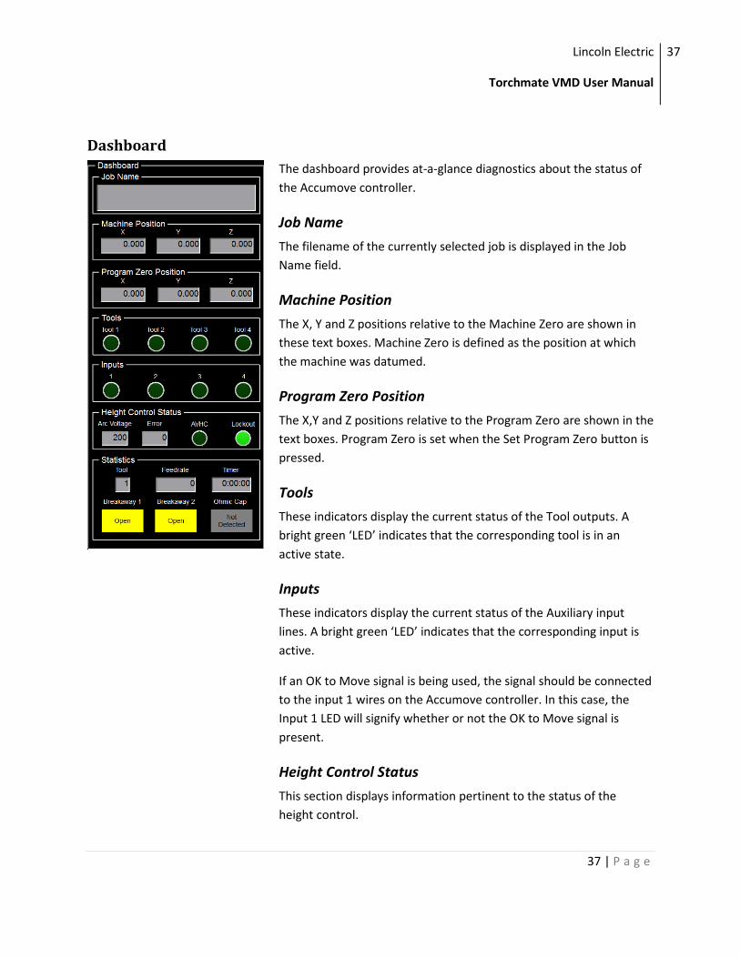
Dashboard
The dashboard provides at-a-glance diagnostics about the status of
the Accumove controller.
Job Name
The filename of the currently selected job is displayed in the Job
Name field.
Machine Position
The X, Y and Z positions relative to the Machine Zero are shown in
these text boxes. Machine Zero is defined as the position at which
the machine was datumed.
Program Zero Position
The X,Y and Z positions relative to the Program Zero are shown in the
text boxes. Program Zero is set when the Set Program Zero button is
pressed.
Tools
These indicators display the current status of the Tool outputs. A
bright green ‘LED’ indicates that the corresponding tool is in an
active state.
Inputs
These indicators display the current status of the Auxiliary input
lines. A bright green ‘LED’ indicates that the corresponding input is
active.
If an OK to Move signal is being used, the signal should be connected
to the input 1 wires on the Accumove controller. In this case, the
Input 1 LED will signify whether or not the OK to Move signal is
present.
Height Control Status
This section displays information pertinent to the status of the
height control.
Lincoln Electric
Torchmate VMD User Manual
38
38 | P a g e
Arc Voltage
Displays the Arc Voltage currently measured by the height control.
Error
Displays the difference, in volts, between the Set Voltage and the Arc
Voltage.
AVHC
ON when the AVHC is enabled and the Z axis is following the set
voltage. Will only turn on when the AVHC is in Auto mode and a cut
is being executed.
Lockout
The AVHC will go into Lockout mode in two instances: when the
torch is within the distance specified by the Distance To Corner
setting, or when the feedrate of the tool drops below a speed
threshold defined by the Corner Speed setting. Read more about
these settings in the Machine Settings section of this manual.
When the AVHC is in lockout mode, the Z axis will stop reacting to
changes in the arc voltage. This helps prevent the torch from ‘diving’
into the material when the torch slows down to make a turn.
Statistics
Tool
Displays the current tool number.
Feedrate
Displays the current tool tip velocity in Inches Per Minute.
Timer
Displays the elapsed job time. Starts when Run Job is pressed and
stops any time a pause or an error occurs.
Breakaway 1 and 2
Displays the status of the breakaway connector. If there is no
breakaway on the system, or if the breakaway feature has been
disabled, these indicators will always be yellow and contain the text
Lincoln Electric
Torchmate VMD User Manual
39
39 | P a g e
‘Open.’
Ohmic Cap
Displays the status of the Ohmic Cap sensor. When the ohmic cap is
in contact with the material this indicator will turn yellow and read
‘Detected.’ This depends on the material and the VFC height control
being properly grounded to the machine.
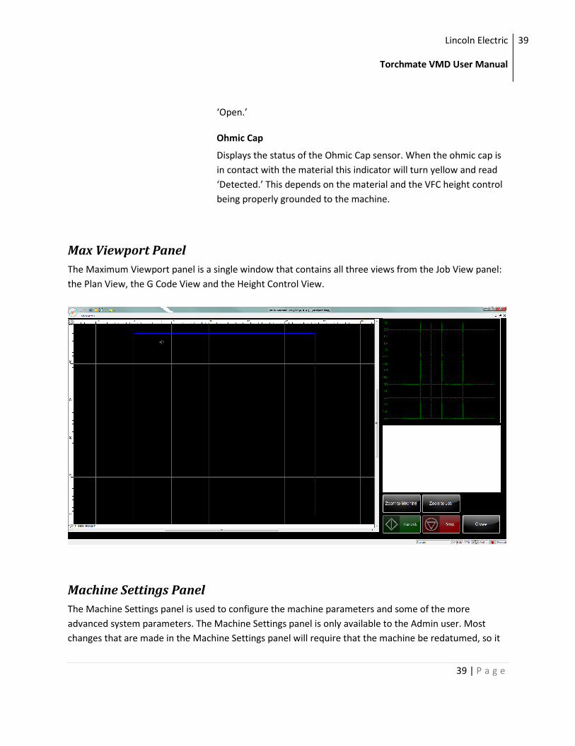
Max Viewport Panel
The Maximum Viewport panel is a single window that contains all three views from the Job View panel:
the Plan View, the G Code View and the Height Control View.
Machine Settings Panel
The Machine Settings panel is used to configure the machine parameters and some of the more
advanced system parameters. The Machine Settings panel is only available to the Admin user. Most
changes that are made in the Machine Settings panel will require that the machine be redatumed, so it
Lincoln Electric
Torchmate VMD User Manual
40
40 | P a g e
is always recommended to jog the machine to the machine zero location before modifying the machine
settings.
The machine settings are loaded when a configuration is loaded. Every Torchmate Machine has a default
configuration that should be loaded when first starting the machine. Read the quickstart guide Startup
Procedure for more information on how to configure the machine.
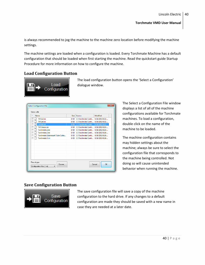
Load Configuration Button
The load configuration button opens the ‘Select a Configuration’
dialogue window.
The Select a Configuration File window
displays a list of all of the machine
configurations available for Torchmate
machines. To load a configuration,
double click on the name of the
machine to be loaded.
The machine configuration contains
may hidden settings about the
machine; always be sure to select the
configuration file that corresponds to
the machine being controlled. Not
doing so will cause unintended
behavior when running the machine.
Save Configuration Button
The save configuration file will save a copy of the machine
configuration to the hard drive. If any changes to a default
configuration are made they should be saved with a new name in
case they are needed at a later date.
Lincoln Electric
Torchmate VMD User Manual
41
41 | P a g e
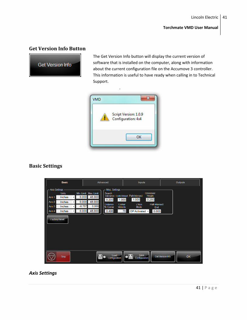
Get Version Info Button
The Get Version Info button will display the current version of
software that is installed on the computer, along with information
about the current configuration file on the Accumove 3 controller.
This information is useful to have ready when calling in to Technical
Support.
Basic Settings
Axis Settings
Lincoln Electric
Torchmate VMD User Manual
42
42 | P a g e
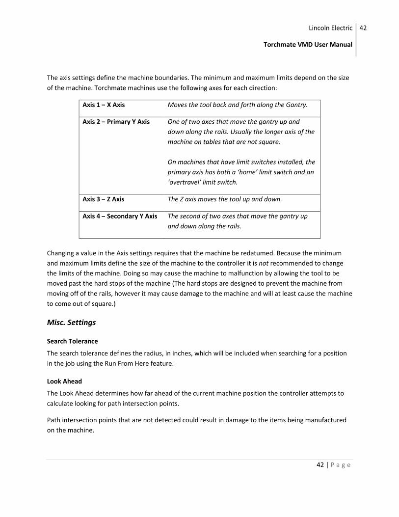
The axis settings define the machine boundaries. The minimum and maximum limits depend on the size
of the machine. Torchmate machines use the following axes for each direction:
Axis 1 – X Axis Moves the tool back and forth along the Gantry.
Axis 2 – Primary Y Axis One of two axes that move the gantry up and
down along the rails. Usually the longer axis of the
machine on tables that are not square.
On machines that have limit switches installed, the
primary axis has both a ‘home’ limit switch and an
‘overtravel’ limit switch.
Axis 3 – Z Axis The Z axis moves the tool up and down.
Axis 4 – Secondary Y Axis The second of two axes that move the gantry up
and down along the rails.
Changing a value in the Axis settings requires that the machine be redatumed. Because the minimum
and maximum limits define the size of the machine to the controller it is not recommended to change
the limits of the machine. Doing so may cause the machine to malfunction by allowing the tool to be
moved past the hard stops of the machine (The hard stops are designed to prevent the machine from
moving off of the rails, however it may cause damage to the machine and will at least cause the machine
to come out of square.)
Misc. Settings
Search Tolerance
The search tolerance defines the radius, in inches, which will be included when searching for a position
in the job using the Run From Here feature.
Look Ahead
The Look Ahead determines how far ahead of the current machine position the controller attempts to
calculate looking for path intersection points.
Path intersection points that are not detected could result in damage to the items being manufactured
on the machine.
Lincoln Electric
Torchmate VMD User Manual
43
43 | P a g e
Path Intersect
This parameter defines the distance along the part programmed cut path, from the path start point, that
the controller path intersection check is inhibited. Entering a zero in this field disables the feature.
Crossover Height
The crossover height determines the distance above the material when the Z axis transitions from a
rapid travel speed to a sensing travel speed for the IHS sequence. The crossover height is only used after
the first pierce; during the first pierce the transition height is defined by the retract height.
Distance To Corner
This parameter control the enabling and disabling of the AVHC. A corner is defined as a point when the
tip speed is zero velocity. The distance defines when the height control should be disabled prior to a
corner and enabled again on the other side of the corner. In plasma cutting applications, disabling the
height control at the start of a deceleration into a corner will prevent the torch from diving into the
corner.
Corner Velocity
This parameter control the enabling and disabling of the AVHC. A corner is defined as a point when the
tip speed is zero velocity. The parameter defines a tip speed below which the height control system will
be temporarily disabled for the duration of time the tip speed is below the corner velocity. The tip speed
is defined as a percentage of the cut speed. For example, if the part is being machine at 100ipm and the
corner velocity is specified at 70% then the automatic height control will only be made active when the
tip speed is greater than 70ipm.
Z Axis Mode
The Z Axis mode on Torchmate machines should only set to O/P Activated (for most applications) or to
3D (for routing applications). This mode alters how the Z axis is controlled during a job. In O/P activated
mode the Z axis will only travel up and down for Tool On commands along with making small
adjustments based on the AVHC. In 3D mode, the Z axis will be controlled by the Z value of the g code
command.
Path Intersect End
Defines the distance back from the end of the programmed cut path during which the path intersection
feature is inhibited. Entering zero for this value disables this feature.
Lincoln Electric
Torchmate VMD User Manual
44
44 | P a g e
Factory Reset Button
Pressing the Factory Reset button will cause most of the user
preferences to revert back to their default values. Below is a list of
the affected settings and their default values. The reset will not go
into effect until after the Torchmate VMD software is restarted.
Setting Default Value
Cap Sense Enabled
AVHC Mode Manual
Pierce Delay 0.5 Seconds
Pierce Height 0.15 Inches
Cut Height 0.06 Inches
Setting Default Value
Retract Height 3.0 Inches
Retract Mode Full
Crossover
Height
0.25 Inches
IHS Optimize
Mode
Always
Pierce Counts 0 (All Tools)
On Dwell 0 (All Tools)
Off Dwell 0 (All Tools)
On Z Enabled for Tool 1
Disabled for all
other Tools
OK To Move Enabled for Tool 1
Disabled for all
other Tools
Kerf 0 (All Tools)
Tool Length 0 (All Tools)
Fixture Offsets X:0 Y:0 (All Offsets)
Stepper Signal
Filter
0.004
Response Gain 25
Damping Gain 15
Static Gain 0.15
Static Limit 400
Lincoln Electric
Torchmate VMD User Manual
45
45 | P a g e
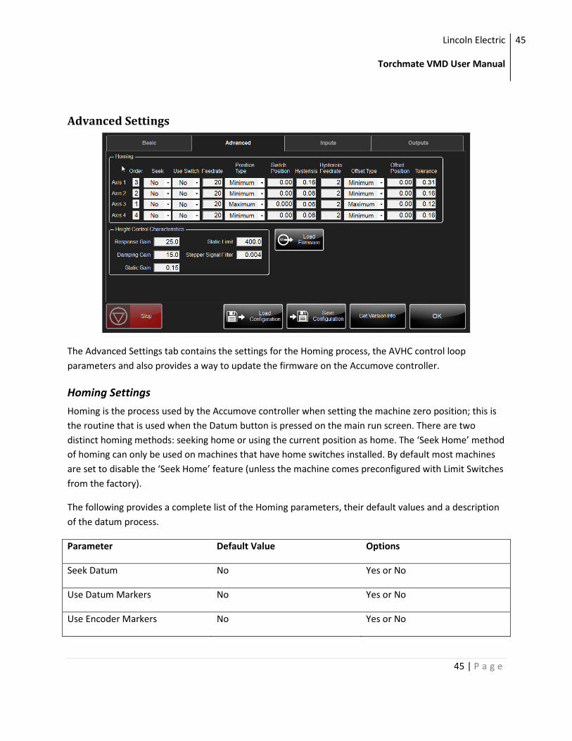
Advanced Settings
The Advanced Settings tab contains the settings for the Homing process, the AVHC control loop
parameters and also provides a way to update the firmware on the Accumove controller.
Homing Settings
Homing is the process used by the Accumove controller when setting the machine zero position; this is
the routine that is used when the Datum button is pressed on the main run screen. There are two
distinct homing methods: seeking home or using the current position as home. The ‘Seek Home’ method
of homing can only be used on machines that have home switches installed. By default most machines
are set to disable the ‘Seek Home’ feature (unless the machine comes preconfigured with Limit Switches
from the factory).
The following provides a complete list of the Homing parameters, their default values and a description
of the datum process.
Parameter Default Value Options
Seek Datum No Yes or No
Use Datum Markers No Yes or No
Use Encoder Markers No Yes or No
Lincoln Electric
Torchmate VMD User Manual
46
46 | P a g e
Datum Order X 3rd, Y 2nd , Z 1st any
Datum Position Type Minimum Maximum, minimum or position
Datum Position 0mm 0 to +/-2^31 counts
Position After Datum Type Minimum Maximum, minimum or position
Position After Datum 0mm 0 to +/-2^31
Datum Feed Rate 50% 0 to 100% of terminal velocity
Datum Hysteresis 1mm 0 to +/-2^31
Hysteresis Feed Rate 5% 0 to 100%
Seek
This parameter determines whether or not each axis needs to move to actively seek a datum target
when datuming. For each axis for which 'Seek Datum' is defined as YES a separate MVC user Input must
be assigned for the datum sensor input.
For each axis, the datuming procedure is described below. For the purpose of this description it is
assumed that the datum target moves with the axis and that the datum detectors are stationary,
however the description is equally valid if the detector moves and the target is stationary:
1. If the 'Seek Datum' parameter is defined as NO skip to step 6.
2. If the datum target is already operating the datum detector, skip to step 3.
3. Accelerate the axis moving the datum target towards the datum detector at the 'Datum Feed Rate'.
As soon as the datum target operates the datum detector, decelerate the axis to a stop.
Note
It is vital that the datum target can never totally pass over the detector or the datum process will not be
repeatable). The initial direction of axis travel is determined by the 'Datum Position Type' parameter. If
the Datum Position Type is defined as 'Position', the initial direction of axis travel, when looking for the
detector, will be positive if the datum position is in the top half of the axis travel and negative if in the
bottom half of the axis travel, as defined by the axis limits.
4. Move the datum target away from the datum detector at the 'Hysteresis Feed rate' until the target is
not operating the detector.
Lincoln Electric
Torchmate VMD User Manual
47
47 | P a g e
5. Continue moving the target away from the detector at the 'Hysteresis Feed Rate' for the 'Hysteresis
Distance', then stop the axis.
6. Move the target back towards the datum detector at the 'Hysteresis Feed Rate' and either stop the
axis immediately the target operates the detector if 'Use Encoder Marker' is set to No or, if set to Yes
the encoder marker is seen.
7. Set the axis position registers to the position defined as the 'Datum Position' parameter
8. When all axes set to 'seek datum' have datumed, simultaneously move all axes, at the maximum
speed set in by the 'Position after Datum' parameters.
Note
If this position is the same as the datum position there will be no axis movement.
Order
The MVC datums each axis in turn, one at a time, in the order specified.
Use Switch
Should always be set to ‘Yes’ if Seek Home is enabled and limit switches are used.
Feedrate
Determines the feed rate or speed that will be used by this axis when initially moving to the datum
position. The Datum Feed Rate is specified as a percentage of the maximum feed (speed) of the axis.
Position Type
Determines whether MVC will expect the datum target to be at the axis minimum, the axis maximum, or
at some position in between. If 'Position' is selected then the position as defined by the Datum Position
parameter is used.
Switch Position
Determines the datum position. If the Datum Position Type is set to be either maximum or minimum
then the relevant axis limits are displayed here automatically. If the Datum Position Type is set to be
'Position' then the datum position should be entered for this parameter.
Hysteresis
This is the distance the target moves off the detector after the detector cannot see the target. This
additional distance overcomes any machine backlash and also ensures that the target is moving at a
steady speed when it next encounters the detector.
Lincoln Electric
Torchmate VMD User Manual
48
48 | P a g e
Hysteresis Feedrate
Determines the feed rate that will be used by this axis during the final stages of datuming and is
generally set much lower than the 'Datum Feed Rate' to provide a repeatable datum position. The
Hysteresis Feed Rate is specified as a percentage of the maximum feed of the axis.
Offset Type
Determines whether MVC will move to a different position automatically at the end of the datum
sequence. The Position after Datum can be set as the minimum, the maximum or as a specified position.
Offset Position
Determines the position the axes will move to at the end of the datum sequence. If the 'Position after
Datum' is set to minimum or maximum, the position is displayed automatically. If the Position after
Datum Type is set to 'Position' then the desired position must be entered here.
Tolerance
The 'Datum Tolerance' is the distance that the axis can be away from the reference position without
MVC interrupting normal operation to display the axis and error dimension.
When MVC is first datumed after power on, it stores this position separately for each axis and uses it as
a reference for all subsequent datums. If a subsequent datum is performed and the difference between
this datum position and the initial datum position is greater than the 'Datum Tolerance' a datum error is
detected and displayed.
Height Control Characteristics
These are the control loop parameters used by the Accumove controller which determine how quickly
the Z axis will respond to changes in the arc voltage, as well as how closely the voltage should be
followed. Generally these settings should not be changed without advice from a technical support
representative. The default values can always be reset by performing a factory reset in the Basic Settings
tab of the Machine Settings window.
Load Firmware
The firmware that runs the Accumove controller is separate from the Torchmate VMD software.
Sometimes new features or improvements may require that the firmware on the Accumove controller is
upgraded. These upgrades will likely be distributed in a new version of the Torchmate VMD software.
Lincoln Electric
Torchmate VMD User Manual
49
49 | P a g e
When a new version of firmware is available
the software will display a notification that the
current firmware is out of date and
recommend that new firmware is loaded.
When this notification is presented the
firmware can be updated from the Advanced
Settings tab of the Machine Settings window.
Firmware Upgrade Instructions:
1.) Press the ‘Load Firmware’ button in the
Advanced tab of the Machine Settings panel.
2.) After pressing the Load Firmware button and
confirmation dialogue box will be shown. At
this point, be sure that you intend to load new
firmware onto the controller.
Updating the firmware takes about 15 minutes
and requires the power to the controller to be
cycled.
3.) Follow the onscreen instructions to update the
firmware. Make sure to wait a full 15 seconds
before re-applying power to the controller.
For the first 5 minutes there will be no user
feedback regarding the update progress.
However, after the existing firmware is erased
a checkmark will appear and progress will be
tracked in the progress bard.
When the update is complete the progress
window will close and the user is taken back to
the Machine Settings window.
Always restart the Torchmate VMD software
after updating the Accumove firmware.
Lincoln Electric
Torchmate VMD User Manual
50
50 | P a g e
Input Settings
The Inputs tab in the Machine Settings window provides access to the configuration of the Inputs on the
Accumove controller. There are three dedicated inputs (Ohmic Cap, Breakaway 1 and Breakaway 2) on
all Accumove controllers and four auxiliary inputs; there are also six additional inputs available on the
Accumove 3 controllers.
The inputs are preconfigured to the factory recommended settings when a configuration file is loaded. It
may be desirable to change the functionality of the machine by manipulating the behavior of the inputs.
Keep in mind that if an OK to Move signal is being used it should be connected to the Aux 1 input signal
regardless of the system being used. Further information about the different types of input lines are
shown in the table below.
The Input status section of this page shows the current status of all of the inputs on the Accumove
controller.
Type
User Inputs
Used within the part program sequence for a user specified function
External Stop
Dedicated function input used as a part program sequence STOP.
Lincoln Electric
Torchmate VMD User Manual
51
51 | P a g e
External Start
Dedicated function used as a part program sequence START or RESUME.
Datums
Dedicated function input assigning the inputs used as axis datums. Overtravels:- dedicated function
input defining the inputs used as axis overtravels.
Operation of an over-travel input stops or inhibits all axis motion and displays an axis Over-travel error
message.
Vacuum 1 and 2
Eedicated function inputs defining which inputs are to be used for monitoring up to two system
vacuums. Vacuum inputs are checked prior to and during part program execution and inhibit or stop
part program execution displaying a `Vacuum Failed' error message.
Tool Retract 1 to 4
Dedicated function input normally used in conjunction with the multiple tool heads. In a multiple tool
head system Tool Retract inputs are used in head selecting to ensure that un-selected heads are
retracted before the part program sequence can continue.
Cut Sense
Dedicated function input typically used in plasma and cutting systems. Cut sense inputs are checked
prior to and during part program execution, if at the wrong level cut sense inputs inhibit or stop machine
motion.
Prg Datum Skip
Allows an external switch to be used to override any datum commands embedded with job program.
Cap Sense
Cap Sense inputs are used with plasma cutting applications for detecting the surface of a conductive
component when setting the pierce and cut heights, for systems fitted with the automatic height
sensing option. During cutting should MVC detect that the cap is touching the material surface the torch
will automatically retract until the cap is no longer in contact with the component.
Active Level
Determines whether the input's active level is high or low effectively inverting the input sense.
Time Out
Lincoln Electric
Torchmate VMD User Manual
52
52 | P a g e
Determines the time out period for all user type inputs setting the maximum wait period for the
required input level before the part program sequence is paused and an error message displayed. The
part program block can be restarted from Visual Machine Designer.
Time Out range is 0 to 9,999ms.
Debounce Time
MVC inputs can be de-bounced to overcome electrical noise. Part program execution will not continue
until the input has been stable for the debounce period.
De-bounce Time range is 1 to 9,999ms.
Output Settings
In addition to the four tool outputs, all Accumove controllers come with four auxiliary outputs.
Accumove 3 controllers come with an additional seven auxiliary output. Each output can be controlled in
the G code (read Appendix A: Accumove G and M Code Programs), and they can also assigned specific
types which have predefined output behaviors. The output parameters are defined in the table below:
Lincoln Electric
Torchmate VMD User Manual
53
53 | P a g e
Parameter Default Value Options
Type On/Off See below
Logic State Normal Normal or Inverted
Power On State Off Off or On
Activation Block See below
Op Delay 0ms 0 to 65,000ms
Activation Time 0ms 0 to 65,000ms
Type
Determines how the output functions. The options are: ON/OFF, Momentary, Pulsed, Periodic, Contact
1, and Contact 2.
• On/OFF outputs turn on when commanded and remain on until turned off.
• Momentary outputs turn off at the start of the activation condition and on at the end of the
activation condition. Momentary outputs are primarily intended to be used as axis breaks where
the break is on when the axis is stationary and releases for axis movement.
Logic State
Each output can be set to Normal or Inverted, this effectively inverts the level of the output. An output
set to 'Normal' turns ON when the output is activated by MVC. An output set to 'Inverted' turns OFF
when the output is activated by MVC.
Power On State
This parameter determines the state of the output after MVC has completed the Power On Self Tests
which immediately follow power on.
Activation
This parameter defines when the momentary output type will be activated. Supported activation
conditions are X axis, Y axis, Z axis, U axis, V axis, W axis, Block, and any axis. If the output type is set to
anything other than momentary this parameter displays "Not Available" and can't be altered.
Lincoln Electric
Torchmate VMD User Manual
54
54 | P a g e
Op. Delay
Defines the delay between MVC turning the output on or off and executing the next programmed block.
This parameter gives time for the output to operate before the part program continues.
Activation Time
This permits the operation of the output to be advanced (- times), or retarded (+ times) to operate early
or late.
Advancing an output can reduce production times. For example in a dispensing application where it
takes 500mS for the fluid to reach the part after being turned on setting the activation time to 450mS
causes the dispense operation to begin 450mS before the machine gets to position.
Lincoln Electric
Torchmate VMD User Manual
55
55 | P a g e
Job Setup Panel
The Job Setup panel contains a host of user preferences for manipulating how the IHS sequence is
performed, as well as several tools for manipulating the job by nesting and/or scaling and rotating the
job.
Height Control Settings
The height control settings panel in the Job Setup window provides a set of user preferences that will be
used to control the behavior of the IHS sequence.
Lincoln Electric
Torchmate VMD User Manual
56
56 | P a g e
Material Thickness
The material thickness has two different uses based on whether or not Ohmic sensing is on. When
Ohmic Sensing is On, the material thickness is used to set a radius for the IHS Optimize feature. In this
instance the material thickness should be set manually by clicking the text box and typing in the
thickness of the material in inches.
When ohmic sensing is Off, the material thickness actually defines the Z axis machine position that
corresponds to the top of the material (a.k.a. material height). To properly set the material thickness in
this case, use the jog keys to jog the tool down until it is just touching the top of the material; press the
Set button under Material Thickness to assign the Z axis position to the Material Thickness.
Ohmic Sensing
Ohmic Sensing can be turned on and off by toggling this button. When ohmic sensing is on, and IHS
sequence will take place whenever a Tool On code is encountered in the G Code (unless it is bypassed
because of the IHS Optimize feature). An IHS Sequence, defined below, is when the controller finds the
top of the material by using the Ohmic Cap sensing feature.
When ohmic sensing is off the IHS sequence will not be performed. If tool has its On Z option enabled
the tool will still travel down to the pierce height before activating the tool; otherwise the tool will be
activated in its current Z axis position.
IHS Sequence
The IHS sequence, or Initial Height Sense sequence, is the process used to detect the material height by
sensing when the ohmic cap comes into contact with the grounded, conductive material. The IHS
sequence is only enabled when Ohmic Sensing is On, and the sequence occurs any time a Tool On
command is encountered in the G Code (unless commanded to be skipped by the IHS Optimize feature).
The IHS sequence behaves differently on the first pierce after a job start/resume than it does on all
pierces thereafter.
First Pierce
1.) Make a rapid travel to the retract height (If in Full Retract Mode, this step is skipped)
2.) Slow down to the detection speed (10ipm)
3.) Continue traveling until the Cap Sense input is triggered, or until the Z Axis reaches the end of its
travel.
Lincoln Electric
Torchmate VMD User Manual
57
57 | P a g e
a. If the axis reaches the end of travel before detecting the material, and IHS Failure
message is displayed. Read the Troubleshooting guide for assistance in resolving this
issue.
4.) Using the detected material height as a reference position, raise the tool to the defined Pierce
Height (this step is skipped if the On Z option for the tool is disabled).
5.) Activate the tool.
6.) If ‘Ok To Move’ is enabled for the tool, wait for the OK to move signal to be triggered on Aux
Input 1.
7.) Dwell for the time indicated in the Pierce Delay field.
8.) Lower the tool to the programmed Cut Height (this step is skipped if the On Z option for the tool
is disabled).
9.) Continue the part program.
All Other Pierces
On all pierces after the first pierce, the IHS sequence begins at the end of the previous cut.
1.) At the end of the current cut, record the material height.
2.) Make a rapid Z axis travel up to the retract height.
3.) Make a rapid X,Y axis travel to the location of the next pierce.
4.) Make a rapid Z axis travel down to a position equal to the Crossover Height above the recorded
material height (0.25” above material by default). The Crossover Height is defined in the
Machine Settings panel.
5.) Perform steps 2-9 of the First Pierce procedure above.
Retract Mode
The Retract Mode can either be in Full or Partial mode. In Full mode, the Z axis will travel all the way to
machine position Z:0 between pierces. When in Full mode, on the first pierce after pressing the Run Job
button, the Z axis will execute the entire IHS sequence at the detection speed (all other pierces after the
first pierce will rapid from Z:0 to the crossover height).
When Partial mode is selected the Z axis will only travel up to the defined Partial Retract Position
between pierces. On the first pierce after pressing the Run Job button, the Z axis will make a rapid move
Lincoln Electric
Torchmate VMD User Manual
58
58 | P a g e
to the Partial Retract Position and then transition to the detection speed for the duration of the IHS
sequence. All other pierces after the first pierce will rapid from Z:0 to the crossover height.
Partial Retract Position
If the software is in Partial Retrace Mode the Partial Retract Position is the Z axis machine position at
which the Z axis transitions from a rapid speed to the detection speed during an IHS sequence. It is also
the position to which the Z axis will raise between pierces.
IHS Mode
The IHS Mode can either be in Always or Optimize mode; toggle between modes by clicking the button.
When the IHS Mode is set to Always, the IHS sequence will occur any time a Tool On command is
encountered in the G Code. When the IHS Mode is set to Optimize, the IHS sequence may be skipped if
the next pierce point is within a radius (determines by the Material Thickness) of the end of the previous
cut. When the IHS sequence is skipped the Z axis rapidly moves the tool down to the pierce height and
activates the tool, skipping the ‘touch off’ portion of the IHS sequence.
Nesting
The nesting feature included with the Torchmate VMD software allows the selected job to be repeated
in several different row/column configurations.
Rows
The number of rows that will be repeated in the nested job. The rows will traverse in a positive direction
along the Y axis from the job origin.
Cols.
The number of columns that will be repeated in the nested job. The columns will traverse in a positive
direction along the X axis from the job origin.
Scrap
The distance between the nested job parts, in inches. At a minimum this value should be set to twice the
tool kerf (i.e. if the plasma kerf is 0.06, the scrap should be set to at least 0.12).
Lincoln Electric
Torchmate VMD User Manual
59
59 | P a g e
Type
There are two types of nesting that can used: straight and staggered (If ‘none’ is selected, no nesting will
be applied). The straight option will result in a standard array of size Row x Column. The staggered array
type will result in an array whose Rows are offset by half the width of the job, resulting in a ‘jagged’
array.
Update
Pressing the update button will create the new nested job based on the specified nesting parameters.
Any time a change is made to one of the parameters (Rows, Columns, Scrap or Type), the update button
must be pressed again to apply the changes.
Note:
Using Nesting and Transforms on the same job may give unexpected results which require manipulating
the Scrap value to achieve the expected array layout.
Transforms
The transforms feature that is included in Torchmate VMD is a tool which allows the selected job to be
scaled in any desired axis,to be rotated or to be mirrored about a selected axis.
Rotate
A value, between 0 and 360 degrees, to rotate the job. Rotations are applied about the X:0, Y:0 program
position and rotate in a counter-clockwise direction. A rotation can only be entered when a job is not in
progress (must be in a reset state). The rotation will be applied immediately after entering the desired
angle, and once it is entered the preview in the plan view will be updated to reflect the new job position.
X/Y Scale
A percentage of the programmed size to scale the selected job. A value of 100 (100%) means that the
job will be executed normally. A value of 200 would double the size of the job, while a value of 50 would
cut the size in half. Each axis must have its scale set separately. A scale can only be entered when a job is
not in progress (must be in a reset state). A scale will be applied immediately after entering the desire
size, and once it is entered the preview in the plan view will be updated to reflect the new job scale.
Lincoln Electric
Torchmate VMD User Manual
60
60 | P a g e
Mirror
The mirror feature allows the selected job to be
mirrored about the X, Y or both axis. Pressing the
Mirror button will open up the Select Mirror dialogue
box. Select the desired axis to mirror the job about. A
mirror can only be applied when a job is not in
progress (must be in a reset state). The mirror will be
applied immediately after pressing the OK button on
the Select Mirror dialogue box.
To remove a mirror, open the Select Mirror Dialogue box and select ‘None’ as the Mirror Style.
Plate Alignment
Plate alignment is a tool which allows the current job to be automatically rotated to fit the orientation of
the plate on the machine bed. This is an especially useful tool when cutting thicker plate that is difficult
to place squarely in line with the X and Y axes of the machine. To use the plate alignment tool to rotate
the job to match the material orientation follow these steps:
1.) Use the Jog keys to position the tool over the lower left corner of the material. Lowering the
tool so that it is closer to the material can help to more accurately position the tool.
2.) Once the tool is positioned over the lower left corner of the plate, press the Align Corner button.
a. After pressing the button, the Align Edge button will be enabled.
3.) Raise the torch and move the tool over any position along the left edge of the material.
Generally, the further away from the corner the tool is positioned, the more accurate the
applied rotation will be.
4.) Once the tool is located above a point along the left edge of the material, raise the tool using
the Z axis jog buttons. Then, press Align Edge to complete the plate alignment process.
CAUTION: This will cause the Z axis to retract to its highest position and then the tool will
automatically jog back to the lower left corner.
Once these steps have been completed the selected job, and any job selected thereafter, will have a
rotation applied that will align the job with the orientation of the plate. In order to remove the
alignment, the plate alignment routine must be followed again. To quickly remove all plate alignments
from the job just press the Align Corner button and then press the Align Edge button without moving
the tool.
Lincoln Electric
Torchmate VMD User Manual
61
61 | P a g e
Tool Library Panel
The Too Library Panel consists of diagnostics, configuration information and user options pertaining to
the four tools that may be used by the Accumove controller. The tool numbers in the Torchmate VMD
software correspond to the tool outputs on the Accumove controller. Though it is not mandatory,
Torchmate strongly recommends using the tools in the following configuration:
Tool
Number
Tool
Description
Tool Output
Type
1 Plasma Close Contact
2 Plate Marker 24V Output
3 Laser Crosshair 24V Output
4 Cut Oxy Gas 24V Output
If this tool configuration is not used it is imperative to ensure that the tool output type is compatible
Lincoln Electric
Torchmate VMD User Manual
62
62 | P a g e
with the selected tool. For instance, putting the plasma start signals onto a 24V output rather than
recommended close contact signal may damage the plasma cutter.
Color
The color of the line that will be drawn in the plan view for the corresponding tool. This is not
configurable.
Kerf
When using tool compensation (G41 or G42) this value defines the offset that will be applied to the
programmed toolpath. The kerf value will also affect how the job is drawn in the Plan view when
running a job; the line drawn during part execution will reflect the size of the kerf.
X/Y Offset
If the tool stations or tool heads are at different positions their position relative to tool 1 can be set
using the X and Y offset positions defined here. These offsets are used by the controller during part
program execution automatically compensating for the different tool positions making part program
generation easy.
To set the tool offset follow the steps below. It is recommended to have a piece of scrap material to use
when setting the tool offsets.
1.) Load the scrap material onto the machine bed. Position tool 1 (the plasma cutter) over the scrap
material. The tool should be positioned in a spot that can be used to pierce the material.
2.) Press ‘Set Program Zero’ after the tool is positioned.
3.) Mark the tool tip position on the scrap material. This can be done with a marker, or by actually
piercing the material.
To pierce the material just press the ‘Toggle’ tool button for tool 1. If the plasma cutter is
powered on and ohmic sensing is enabled this will cause the torch to lower to the material and
then pierce the plate. Press ‘Toggle’ again to turn the tool off.
4.) Using the jog keys, raise tool 1 and then move the machine so that tool 2 is positioned over the
pierce point (or the marked point).
5.) Once tool 2 is positioned over the pierce point, press the ‘Set’ button next to the Y Offset value
to set the tool offset. If the offset is being assigned for tools 3 or 4 the same process is used but
the corresponding ‘Set’ button should be pressed.
Lincoln Electric
Torchmate VMD User Manual
63
63 | P a g e
Length
The length value is used when the Z Axis Mode is set to 3D in the Machine Settings panel. The Length
defines a Z axis offset to be used in routing applications. When in used, all Z axis moves will be offset by
this value. To properly set the tool length, lower the selected tool so that it is touching the top of the
material. Then, press the ‘Digitize Tool’ button to set the tool length. The desired tool will need to be
selected in the ‘Select Tool’ box before digitizing the tool length.
On Dwell
The On Dwell defines the length of time, in seconds, to wait between activating the tool with a Tool On
command and continuing the G Code execution. This is useful if the tool takes a certain amount of time
before it is actually activated (i.e. letting air pressure build in the plate marker).
Note: The On Dwell and the Pierce Delay will be added together. If using a pierce delay for a plasma
cutter it is recommended to always leave the On Dwell at zero.
Off Dwell
The Off Dwell defines the length of time, in seconds, to wait between turning the tool off and continuing
with the G Code execution. This is useful is the tool takes a certain amount of time to turn off (i.e. letting
a spindle slow down).
Pierce Count
The pierce count keeps track of how many times the tool has been activated. This is a useful feature for
tracking consumable life. The count is incremented any time a Tool On command is encountered in the
G Code.
The pierce count should be reset any time the consumables are changed. To reset the pierce count press
the ‘Reset’ button next to the pierce count number. The pierce count will also be reset after a factory
reset.
Activate
The activate button toggles the tool on or off. The tool will only activate if the software is in Active Run
mode (on the main screen). If ohmic sensing is enabled, tool 1 will execute the IHS sequence when it is
toggled on. The IHS sequence can be halted by pressing the ‘Stop’ button.
Remember that the Toggle button will need to be pressed again to turn the tool off. When using a
plasma cutter, even if the torch loses the arc, the tool needs to be toggled off before exiting the panel.
Lincoln Electric
Torchmate VMD User Manual
64
64 | P a g e
OK To Move
This option is used to tell the controller if the OK To Move signal must be received before continuing
part execution after a Tool On command. The OK to Move signal is a common signal in plasma cutting,
and it must be wired to Aux Input 1 on Accumove systems.
When OK To Move is enabled, the timer used for the pierce delay will not begin until after the OK to
Move signal is received on the Input 1 line.
Z Axis
When this option is enabled, the Z axis will move the selected tool to the pierce height before activating
the tool, and then to the cut height after the tool has been activated. If the option is disabled, the tool
will be activated at its current location.
Note: If the Z axis is disabled, but the ohmic sensing is left On, this means that the controller will run the
IHS sequence and then turn the tool on while it is touching the material.
Lincoln Electric
Torchmate VMD User Manual
65
65 | P a g e
Utilities
The Utilities are a set of tools that which add to the default functionality of the Torchmate VMD
software. The currently available utilities are the shape library and the fixture offsets.
Shape Library
The shape library consists of 28 configurable shapes which can be used to create GM job files. Pressing
the Shape Library button from the Utilities screen will launch the Shape Browser.
Lincoln Electric
Torchmate VMD User Manual
66
66 | P a g e
The shape browser displays all of the
available shapes. To create a shape,
select a template by clicking the image
of the shape and then press the OK
button to open the Shape Dimensions
wizard.
The Shape Dimensions wizard contains a
host of parameters that must be defined
before creating the GM job file.
Tool
Use this menu to select the tool that the
job should be created for. If no tool is
selected, the controller will use
whatever tool is currently selected to
execute the job.
Feedrate
Enter the feedrate that the job should
be run at. If using a plasma cutter, this
value should be retrieved from the cut
chart for the plasma cutter based on the
material thickness and power settings of
the power supply.
If this field is left empty the controller will attempt to execute the job at the maximum speed.
Shape Dimensions
Lincoln Electric
Torchmate VMD User Manual
67
67 | P a g e
The main area of the Shape Dimensions wizard will show a template of the shape being created with
text boxes that correspond to each definable dimension. To set a dimension click inside the text box;
press the OK button on the numeric entry pad to confirm the dimension (pressing OK will exit the shape
wizard). As dimension are entered, the preview window in the upper right portion of the window will be
updated to reflect the input dimensions. Error messages may also be displayed in the preview window
when invalid dimensions are entered; correct the corresponding dimension to make the error message
go away.
Shape Options
The lower right corner of the shape wizard contains a handful of options that will be applied to the job;
these options change slightly depending on the shape being designed.
Hole/Pierce
Selects whether the shape will be cut as an ‘inside’ part or an ‘outside’ part. Mostly affects the travel
direction of the job.
Lead In
Defines the length of the lead in that is added to the beginning of linear cuts. This value should be
entered in inches.
Lead Out
Defines the length of the lead out that is added to all cuts. This value should be entered in inches, and
can be left at zero if no lead out is needed.
Lead In Radius
Defines the radius of the lead in to use on arc cuts. This value should be entered in inches and must be
less than the radius of the arc to be cut.
Holes
For shapes that contain an interior pattern of cuts, this field selects how many of the patterned shape
cuts will be made for the final shape.
Lead-In Wizard
Not a supported feature at this time. To be used in a future release of the software.
Fixture Offsets
Fixture offsets are list of X, Y coordinate pairs that can be saved and used as reference points. Fixture
offsets can be valuable tools when implementing jigs (or fixtures) in production environments, and for
Lincoln Electric
Torchmate VMD User Manual
68
68 | P a g e
simply saving machine locations that are important for your application. The Fixture Offset utility
provides a list of the available offsets and a method of setting the offsets for use in jobs.
When using fixture offsets it is important to remember that they are saved as machine coordinates. To
effectively use fixture offsets the machine zero location must always be consistent. The best way to
ensure that the machine zero is set consistently is to use Datum (or Home) switches with the Accumove
controller.
Torchmate VMD has five available fixture offsets that can be assigned: G57 – G61. These fixture offsets
will be saved until they are over-written with a new value or until a factory reset is performed.
Setting Fixture Offsets
1.) Set Machine Zero in a location that can be repeated any time the controller needs to be re-
datumed. This happens automatically is the machine is configured to use home switches;
otherwise, manually jog the machine to a position that you are comfortable finding again after a
machine reboot and press the ‘Datum’ button.
2.) Jog the tool to the desired location to be saved to a fixture offset.
Lincoln Electric
Torchmate VMD User Manual
69
69 | P a g e
3.) Press the ‘Set’ button next to the offset to be assigned. After pressing the button, the X and Y
offset values will be updated to reflect the current machine position.
These values can be reset any time by pressing the ‘Set’ button again. To clear all of the fixture
offsets, perform a factory reset, or go to the machine zero location and press ‘set’ for all of the
offsets.
Moving to a Fixture Offset
These steps will move the tool to the desired fixture offset position when preparing to run a job (i.e. the
job isn’t running yet).
1.) In the Fixture Offsets utility, click on the ‘Point’ tab in the Jog section of the panel.
2.) Select ‘Datum’ mode
and ‘Rapid’ for
speed.
3.) Enter the X and Y
offset positions into
the X and Y point
positions.
4.) Press the ‘Go’ button
to move the machine
to the designated
fixture offset.
Using a Fixture Offset
in a Job
Fixture offsets can be called from a job to offset all programmed positions to be offset relative to the
fixture offset position. Fixture offsets do not nest, if successive fixture offsets are called, only the most
recent offset is used to offset the programmed positions. To clear offsets a Cancel Offset G code
command must be given (G56). It is recommended to include a cancel offset command at the beginning
of all part programs if implementing fixture offsets to prevent unintended offsets from previous jobs
being used.
Syntax
G57
Lincoln Electric
Torchmate VMD User Manual
70
70 | P a g e
Result
All programmed moves after the G57 in this example would be offset by the value saved in the G57
fixture offset. This offset would continue to be applied until the controller is given another fixture offset
or until the controller is given a Cancel Offset command (G56). This will not happen automatically at the
end of a job.
Job Queue Control
Not a supported feature at this time.
Advanced Configuration
Most of the configuration options covered in this manual deal directly with the machine or the behavior
of the tool while processing a job. The Torchmate VMD software also has a set of options which can
configure the software to behave differently. The following section will demonstrate how to modify
some of the available software options to set some user preferences, however it is important to realize
that changing the settings that are not covered in this manual may cause the machine to behave
unexpectedly and should be avoided.
Torchmate VMD Options
The Torchmate VMD Options can only be accessed by the Admin
user. To get to the Torchmate VMD options panel, click the small
grey gear shaped icon in the top left corner of the software.
Lincoln Electric
Torchmate VMD User Manual
71
71 | P a g e
Changing the Default IP Addresses
The Accumove controller comes configured for a specific IP configuration. There are two IP addresses
that concern the Accumove controller: the IP address of the controller and the IP address of the
computer that is to be connected. Both of these addresses are stored in the memory of the controller
and they can be configured from the VMD Options window.
By default, the IP Addresses come preconfigured with the following values:
Accumove Controller IP Address 192.168.1.7
Local IP Address (Connecting Computer) 192.168.1.6
While this configuration will generally work fine, some Local Area Networks may require that both the IP
address of the computer and the controller be changed to follow stricter network requirements. To
change the IP addresses use the following steps:
1.) Using the supplied Ethernet Crossover cable, connect directly to the controller using the default
configuration. The computer connecting to the controller will need to be assigned with the IP
address 192.168.1.6 for this step.
2.) Launch the Torchmate VMD software, log in as the Admin User (password 1234), and open the
VMD Options Window.
Lincoln Electric
Torchmate VMD User Manual
72
72 | P a g e
3.) Click the ‘Connections’ tab to open the IP Address configuration window.
4.) The MVC IP Address field contains the IP Address of the Accumove controller. Enter the desired
IP address for the controller in this field.
5.) The Local IP Address field contains the IP Address that the Accumove will attempt to make a
connection with. Whichever IP address will be assigned to the computer should be entered into
this field.
6.) Press the ‘OK’ button to save these changes. Torchmate VMD will display a dialogue box
explaining that a network change has been detected; follow the onscreen instructions to
complete the IP Address configuration.
Lincoln Electric
Torchmate VMD User Manual
73
73 | P a g e
7.) Press OK to close the dialogue box. Press the ‘Log On’ button in the main screen, and then log
on either as the Operator or as Admin again (it doesn’t matter which one). Once logged in, press
Ctrl-Shift+F5 on the keyboard at the same time. Press ‘OK’ on the dialogue box asking if the
default settings should be overwritten. Now the settings have been saved to the controller and
to the software. Close Torchmate VMD.
8.) If changes were made to the Local IP Address, change the IP address of the computer to match
the new address before opening the VMD software again.
9.) Open the VMD software again to verify connectivity.
Configuring the ‘Select Jobs’ Default Directory
By default the ‘Select Job’ dialogue box displays jobs found in the Jobs folder of the Torchmate VMD
installation directory (C:\Torchmate Controller Data\Jobs). While the browse button can be used to find
jobs in other locations on the computer, the software can also be configured to automatically check
other locations for valid job files.
To configure Torchmate VMD to look in additional folders for job files follow these steps:
1.) Using the supplied Ethernet Crossover cable, connect directly to the controller using the default
configuration. The computer connecting to the controller will need to be assigned with the IP
address 192.168.1.6 for this step.
2.) Launch the Torchmate VMD software, log in as the Admin User (password 1234), and open the
VMD Options Window.
a. Click the ‘Directories’ tab to open the IP Address configuration window. Then select
‘Jobs’ from the drop down menu.
Lincoln Electric
Torchmate VMD User Manual
74
74 | P a g e
3.) Pressing the ‘Add’ key will open up a standard Windows directory browser. Find the folder to be
added to the default Jobs directory, click on the folder in the browser to highlight it and then
press the ‘Select’ button to add the folder.
Lincoln Electric
Torchmate VMD User Manual
75
75 | P a g e
The next time the ‘Select Job’ button is pressed from the main Run Panel, the jobs in the selected folder
will be displayed in the ‘Select Job’ browser without needing to browse the computer for them.
Troubleshooting
The following list of issues are common situations encountered when running the Accumove controller
with the Torchmate VMD software. If you don’t find your problem here, or if the recommended course
of action does not resolve your issue, please call or e-mail Technical Support.
Issue Possible Causes Recommended Course of Action
Can’t connect the Accumove
Controller
Accumove not powered on
Wrong Ethernet cable being
used
The IP Address is not configured
correctly
Torchmate VMD is being blocked
by a firewall
Make sure that power is applied
to the Accumove controller.
If using a direct connection
between the controller and the
computer, an Ethernet crossover
cable must be used (not a
regular Ethernet cable). A red
crossover cable is included with
the machine.
Ensure that the computers IP
address has been set to
192.168.1.6
Check the windows firewall
settings to ensure that
Torchmate VMD is allowed to
communicate through the
network.
Error Message-
IHS Failure: Ensure the VFC is
grounded to the material
The ground wire from the VFC
Height Control Electronics is not
properly connected
The Z Axis reaches machine
position -6.75 before the ohmic
cap detects the material
Ensure that the plasma ground
cable is connected to the
machine ground, and also ensure
that a wire has been placed
connecting the VFC height
control ground to the machine
ground.
Physically lower the torch in the
Lincoln Electric
Torchmate VMD User Manual
76
76 | P a g e
torch holder by loosening the
clamp screws and sliding the
torch further down the clamps.
Error Message-
IHS Failure: Remove ohmic cap
and clear any slag from the
consumable
There is material stuck between
the torch electrode and he
ohmic cap
Remove the shield cap from the
torch and clear out any slag that
has accumulated.
Error Message:
External Pause Detected
A pause input (i.e. the
breakaway) has been triggered
When this occurs, the breakaway
indicators in the Dashboard will
also light up. Manually set the
torch back into the torch
breakaway cradle.
The dashboard indicators will be
turned off when the torch is
properly set.
If the breakaway is ‘falsely’
triggering, consider adjusting the
magnet in the torch breakaway
to increase the magnetic force
holding the torch in position.
Alternatively this feature can be
disabled by changing the ‘Pause’
type for the Breakaway 1 and 2
peripherals to ‘User’ in the
Inputs tab of the Machine
Settings panel.
Error Message:
Overtravel Detected
An overtravel switch has been
activated.
After triggering this error the
controller assumes that the
position has been lost and
requires that the machine be re-
datumed.
To avoid this error, do not allow
the machine to be jogged to the
Lincoln Electric
Torchmate VMD User Manual
77
77 | P a g e
point at which the overtravel
switches are engaged.
In theory, these switches should
only be activated if the machine
has lost position or if it was
improperly datumed.
The overtravel switches protect
the machine from unnecessary
collisions with the hard stops,
thereby reducing the chance of
coming out of square and/or
reducing mechanical wear.
Error Message:
Limit exceeded in …
The machine is being
commanded to move outside of
the machine limits.
In the plan view, ensure that the
entire job lies within the blue
outline that defines the machine
limit. This may require resetting
the program zero and/or
repositioning the material on the
machine bed.
If the limit is being exceeded in
the Z direction, verify the
material thickness has been set
properly and reset the Z
position.
Torch Crashes Into Material
during IHS Sequence
The partial retract height has
been set too low
Ohmic sense is disabled and the
material thickness has been set
incorrectly
The Z axis has lost position
Ensure that the partial retract
height has been set to a level
that is safely above the material
height.
Reset the Z position at the top of
the Z Axis slide.
Verify that the material thickness
has been set appropriately.
Lincoln Electric
Torchmate VMD User Manual
78
78 | P a g e
Job stops executing after the
torch touches the material
The breakaway is being triggered
when the torch touches the
material.
Reduce the ‘debounce’ time for
the cap sense input
Increase the magnetic holding
force on the breakaway by
adjusting the magnet position
Disable the breakaway in the
inputs tab of the Machine
Settings windows by changing
‘Pause’ to user for breakaway 1
and 2.
Machine stops moving during a
‘Move To Hear’ jog before
reaching the final destination.
The breakaway is being triggered
during the job motion
Increase the ‘debounce’ time for
the breakaway inputs
Increase the magnetic holding
force on the breakaway by
adjusting the magnet position
Disable the breakaway in the
inputs tab of the Machine
Settings windows by changing
‘Pause’ to user for breakaway 1
and 2.
All the buttons are disabled The controller is not connected.
The software lost
communication with the
controller
Power down the Accumove
controller and close the
Torchmate VMD software. Wait
15 seconds. Power the
Accumove controller on and
then start the software again.
Machine won’t jog A Datum has not been
performed after powering the
controller on.
The software has lost connection
with the controller
Datum the machine
Power down the Accumove
controller and close the
Torchmate VMD software. Wait
15 seconds. Power the
Accumove controller on and
Lincoln Electric
Torchmate VMD User Manual
79
79 | P a g e
then start the software again.
Can’t load a job The controller is not connected.
The software lost
communication with the
controller
Power down the Accumove
controller and close the
Torchmate VMD software. Wait
15 seconds. Power the
Accumove controller on and
then start the software again.
Job is rotated automatically
when it is loaded
There is a rotation in the ‘Rotate’
field in the Job Setup panel.
A Plate Alignment has been
performed earlier
Set the Rotate value in the Job
Setup window to zero.
Clear the plate alignment by
pressing the ‘Align Corner’
button and then the ‘Align Edge’
button without moving the tool
in the Job Setup window
Torch is firing in the air The IHS Sequence was stopped
during the first pierce after the
‘Run Job’ button is pressed.
This is a known issue that occurs
in the following situation:
1.) IHS Mode is set to
Optimize
2.) The user stops the job in
the middle of the first
IHS sequence after
starting/resuming a job.
3.) The user presses ‘Run
Job’ to resume the job
This action will cause the torch
to fire in the air. If the job is
stopped in this situation, a
resume should be performed by
right clicking on the plan view
and performing a ‘Run From
Here’ operation at the point
where the job should be
Lincoln Electric
Torchmate VMD User Manual
80
80 | P a g e
restarted.
Appendix A: Accumove G&M Code Programs
A program is a sequence of instructions to be executed by the controller. The instructions need to be in
format that the controller can understand and yet be flexible enough to achieve the operator's needs. A
G&M code program will generally consist of a program name, a sequence of G codes and M codes and
and with an M02 command. The program length will vary depending upon the functions it is to achieve.
The following sub sections provide details of the types of data that can be included within a program.
Block Format
Each instruction (or command) in the program sequence needs to follow a defined "block" format if it is
to be understood correctly by the controller. Each command starts with a command identification code
followed by a sequence of characters and numbers and ending in a delimiter code.
The command identification code defines the type of command. There are a large number of different
command types supported by MVC and these are listed and described in detail further into this chapter.
The command codes are split into two, G Codes for Preparatory function and M Codes for
miscellaneous functions. The G or M code is then followed by a number. Generally the code numbers
are 2 digits long however the leading 0 can be discarded e.g. G01 or G1 are both valid codes for the
linear move command.
The sequence of characters and numbers which follow the command code are dependent upon the
command code used but generally identify a parameter by the use of a letter and a distance by the use
of a number. Again the character sequences that are to be used for each command are listed in detail
under the command name later in this chapter.
The delimiter code identifies the end of the command code sequence.
Example
G01X10Y15<CR>
The command that is defined above has the command code G01 which defines the command as a linear
move. The sequence of X10Y10 which follows the command code identifies that the X axis must move to
position 10 and the Y axis must move to position 15.
The carriage return character (<CR>) terminates the command White space characters (<SPACE>) and
(<TAB>) are ignored.
Lincoln Electric
Torchmate VMD User Manual
81
81 | P a g e
Note
Special character codes are identified in this manual within < > symbols.
Block Numbers
In order to make the program sequence easier to read and make it easier to refer to a specific command
within the program, many software packages support block numbers in the form of an "N" followed
immediately by a number. The Accumove controller ignores all block numbers.
Example
N25G01X10Y15<CR>
Our previous example has now been extended to include a block or command number showing it is at
position 25 in the program sequence.
Modal Programming
A program may be constructed with every block being prefixed with a G or M code. However to reduce
file sizes when many blocks of the same type are being streamed then the G or M code need only be
specified at the start of the sequence and the controller will assume the same code for the subsequent
commands. For example if we were to stream many vectors we could send the data using the expanded
methodology as follows:
G01X1.234 Y3.456
G01X2.32 Y45.45
G01X4.33 Y34.3
G01X6.44Y8.98
Alternative to reduce the file size it may be sent as follows:
G01X1.234 Y3.456
X2.32 Y45.45
X4.33 Y34.3
X6.44Y8.98
The key point is the last G or M code parsed will the one applied to the next block that doesn’t have a
code specifically defined.
If an axis coordinate is defined and the previous G or M codes was not a move block then an error
message indicating the last block was not a move.
Lincoln Electric
Torchmate VMD User Manual
82
82 | P a g e
Program Comments
Another tool used by programmers to make the program sequences easier to understand by a human
reader is to include comments. Comments are blocks of text which describe the actions of the command
sequences or the reason for the command sequence but which will be ignored by the controller.
Example:
The following lines of text show an example of a multiple line comment taken from the beginning of a
G&M code program.
‘The following program sequence<CR><LF>
‘is to be used on the<CR><LF>
‘gasket head assembly
G Code Commands
The following text will provide the command code title, a description of the command's function, details
of the syntax for the command, any notes highlighting issues around the command and finally an
example of the command as it would appear in a program sequence.
G00 RAPID
This G code provides the controller with a position that it must move all defined axes to, at terminal
velocity.
Syntax
G00XnYnZn
where G00 defines rapid block type and Xn defines an X axis position, Yn a y axis position and Zn a z axis
position.
G01 LINEAR
This G code provides the controller with a position that it must move all defined axes to, at the defined
axis feedrate.
Syntax
G01XnYnZnFn
where G01 defines the block type ie Linear, Xn defines an x axis co-ordinate position, Yn a y axis co-
ordinate position and so on. FXn defines the feedrate used for the X axis motion defined in percentages
of the maximum systems feedrate.
Lincoln Electric
Torchmate VMD User Manual
83
83 | P a g e
If more than one axis is defined in a move with more than one axis feedrate each axis will move at such
a rate that all axes will arrive at the desired position at the same time. The axis that will take the longest
to get to its final position due to either the distance of the speed of motion is called the controlling axis.
If a single axis move is defined, that axis will move at the axis feedrate defined for it. If no feedrate is
defined the feedrate last defined for that axis will be used.
Note
The G01 part of the command can be omitted allowing single or multiple axis linear moves to be
defined. e.g. XnZn.
G02 CLOCKWISE ARC
This G code provides the controller with the co-ordinates that it needs to produce a clockwise arc in the
XY plane. The centers define the plane the arc will execute. Other axes may be move with the arc
contouring axes for example Z to create a helical.
End-Point/Centre Arcs Absolute Centers
Syntax
G02XnYnZnFnCXxCYy
where G02 defines the block type ie clockwise arc, Xn defines the x axis coordinate position of the end
of the arc, Yn the y axis co-ordinate position of the end of the arc etc, Fn defines the feedrate used for
the x axis, as a percentage of the maximum feedrate or units per minute depending upon the setting of
the feed control parameter.
End-Point/Centre Arcs Relative Centers
Syntax
G02XnYnZnFnIcJc
where G02 defines the block type ie clockwise arc, Xn defines the x axis coordinate position of the end
of the arc, Yn the y axis co-ordinate position of the end of the arc etc, Fn defines the feedrate used for
the x axis, as a percentage of the maximum feedrate or units per minute depending upon the setting of
the feed control parameter.
In and Jn to define relative centers to the start point
The plane the arc executes is controlled by the center definition. To define an arc in the XZ plane the arc
centers should be specified for X and Z axes.
Lincoln Electric
Torchmate VMD User Manual
84
84 | P a g e
An example of an arc defined for the XZ plane is as follows.
G02XnZnCXxCZz
To define an arc in another plane for example YZ then specify the arc as follows.
G02YnZnCYyCZz
G03 COUNTER CLOCKWISE ARC
This G code provides the controller with the co-ordinates that it needs to produce a counter clockwise
arc in the xy plane. As with the Clockwise arc there are three types of arc supported by MVC. The syntax
for each of these are types is the same as for the clockwise blocks except for the use of G03 instead of
G02.
G04 DWELL
This G code provides the controller with a time that is to be used for a dwell (timed delay) in the
program sequence execution.
Syntax
G04Dn
where G04 defines the block type i.e. a dwell, and Dn defines the time in milliseconds for the execution
delay.
G05 MOVE UNTIL INPUT
This G code command allows a linear move to be programmed along with an input status command and
or torque component. The move will be executed as a linear move until the specified condition is met.
At this time the axes will decelerate to a stop. If the move completes before the input condition is
satisfied an error will be generated.
Multiple axis end points and input conditions may be defined for amove until input block.
Syntax
G05XnYnZnFnIn+Tt
Lincoln Electric
Torchmate VMD User Manual
85
85 | P a g e
G10 MIRROR X
This command reflects all following moves in the X axis about the current X axis position. Mirror X
commands are nested to 10 levels.
Syntax
G10
G11 CANCEL MIRROR X
This cancels the last Mirror X command removing it from the nest
Syntax
G11
G12 MIRROR Y
This command reflects all following moves in the Y axis about the current X axis position. Mirror Y
commands are nested to 10 levels.
Syntax
G12
G13 CANCEL MIRROR Y
This cancels the previous Mirror Y command removing it from the nest.
Syntax
G13
G14 ROTATE
This command rotates all following moves about the current position or the given center. Rotate
commands are nested to 10 levels.
Syntax
G14XcYcA<a>
Where: <a> = Angle of rotation in degrees.
Lincoln Electric
Torchmate VMD User Manual
86
86 | P a g e
Xc and Yc define the center of rotation.
G15 CANCEL ROTATE
This cancels the last Rotate command removing it from the nest.
Syntax
G15
G20 PROGRAM SCALE
This command results in all following moves being scaled by given percentage relative to the given
position. If a position is not given then the current position is used.
Program scales are accumulative, i.e. two successive scale factors of 10% will result in a scale factor of
1%.
Syntax
G20S<s>[,X<x>][,Y<y>]
Where: <s> = % scale factor. Range = 0.001% to 8000%
<x> = x position
<y> = y position
G24 CANCEL PROGRAM SCALE
This cancels the previous program scale.
Syntax
G24
G24 GENERIC MIRROR
This command allows any axis or combination of to be reflected about a given center and will nest to 10
levels.
Syntax
G24X<x>Y<y>Z<z>
Where the coordinate selects the plane and defines the reflection center.
Lincoln Electric
Torchmate VMD User Manual
87
87 | P a g e
G25 CANCEL GENERIC MIRROR
This command cancels the last generic mirror and removes it from the nest.
Syntax
G25
G40 CANCEL TOOL COMPENSATION
This G code turns off any tool compensation that is being applied to the program sequence in the
controller. This block cancels either the G41 or the G42 blocks.
Syntax
G40
Note
Tool Compensation is an extra cost option on the controller and as such will not be available on the
standard controller.
G41 TOOL COMPENSATION LEFT
This G code command allows the controller to compensate for the diameter of the cutting tool without
the programmer having to alter the program sequence for each individual tool. If the current tool's
diameter is zero then no compensation will be seen.
When this command is executed the controller will enter tool compensation mode. The controller looks
through the next few command blocks, which it is about to execute, and calculates the path to the left
of the programmed path of a distance equal to the radius of the currently selected tool.
Syntax
G41
The distance that the controller looks ahead is set within the configuration file for the controller.
For the resulting job to match the requirements the programmer will need to create the job sequence
taking into account that compensation will be used.
The usual programming format for the use of the cutter offsets is to take up a position away from the
work piece you will be creating, enable the cutter compensation and move towards and then around the
work piece. Then disable the compensation and finally move away from the work piece.
Lincoln Electric
Torchmate VMD User Manual
88
88 | P a g e
If you are milling a closed profile you should not start the profile at a corner as this will result in the
cutter path not closing properly. The position where the offsets are activated is different to the position
where the offsets are deactivated making repetition of the profile impossible. The starting point for a
closed profile should be half way along one of the sides of the profile e.g. on a square, half way along
one of the sides.
Path start and end intersection parameters allow the user to configure MVC to ignore vector intersects
up to a defined distance from the start of cut path and a preset distance away from the end of the cut
path. If badly designed geometry is presented to the control then a entire enclosed profile may be
filtered and not executed as a result of vectors at the start and end of the profile intersecting one
another given the cutter diameter.
G42 TOOL COMPENSATION RIGHT
This G code operates in the same way as G41 above however the compensation is applied to the right of
the programmed path not the left. All of the other text that applies to the G41 block also applies to this
block.
Syntax
G42
G54 PROGRAM OFFSET
This G code defines a program offset in one or more axes. The specified distance will offset all moves
following this command. Offsets will nest to a maximum level of 10.
Syntax
G54XnYnZn
G56 CANCEL OFFSET PROGRAM
This G code removes the last offset commands from the nest cancelling the last active G54 offset
command.
Syntax
G56
G70 IMPERIAL UNITS
This G code changes the units used by MVC to be Inches. Any subsequent blocks are assumed to be
defined in imperial measurements and are executed as such.
Lincoln Electric
Torchmate VMD User Manual
89
89 | P a g e
Syntax
G70
Note
MVC controller assumes that the data is in imperial units and will remain in this mode until the units are
changed using G71 block. At the start of each program the imperial units will be used no matter what
the current units setting was at the end of the last program.
G90 ABSOLUTE MODE
This G code when executed sets the mode of execution of all subsequent blocks to be Absolute.
Absolute mode is when the destination points defined by blocks are expressed as a distance from the
absolute datum position of the system. i.e. the system moves to the defined position no matter what its
current position.
Syntax
G90
Note:
MVC controller defaults to Absolute mode at the beginning of each program sequence.
G91 INCREMENTAL MODE
This G code when executed sets the mode of execution of all subsequent blocks to be Incremental.
Incremental mode is when the destination points defined by blocks are expressed as a distance from the
current position of the system. i.e. the system uses the defined movement as an offset to its current
position.
Syntax
G91
Note:
MVC controller defaults to Absolute mode at the beginning of each program sequence.
G98 ABSOLUTE DATUM
This G code when executed moves all of the axes, defined as having fixed datum positions, to their
datum detectors. If an axis is defined as not having a fixed datum position the current position is taken
as the datum position.
Lincoln Electric
Torchmate VMD User Manual
90
90 | P a g e
If a position after datum is defined as part of the configuration file then once the datum process has
been completed the system moves the axis to that defined position before executing the next block in
the sequence.
Syntax:
G98XnYnZn or G98
If no parameters are defined then the explanation above applies. If parameters are defined then only
the axes defined are datumed and the position is used as the position after datum.
This extension to the more usual datum format of no parameters being specified. This command allows
a system to datum one or more axes within a program without affecting the current positions of the
other axes.
M CODE COMMANDS
The following text will provide the command code title, a description of the command's function, details
of the syntax for the command, any notes highlighting issues around the command and finally an
example of the command as it would appear in a program sequence.
M00 PROGRAM HALT
This command pauses the program and prompts the operator to resume by pressing the start button.
Syntax
M00 or M
M02 END OF ELEMENT
This command terminates program execution.
Syntax
M02
This block should be the last command in any program sequence.
M06 TOOL CHANGE
This M code selects the next tool. Each tool on MVC has a set of tool parameters associated with it. By
changing the tool the controller picks up the new parameters such as length and diameter from the tool
library and uses these during subsequent program execution.
Lincoln Electric
Torchmate VMD User Manual
91
91 | P a g e
Syntax
M06T<n> D<d>
Where n is the number of the tool that will be used from this point on in the program sequence. At
present the number of tools on MVC is limited to 8. D is the tool diameter specified using the current
units.
M20 AUXILIARY OUTPUTS
This M code controls the status of selected auxiliary outputs.
Syntax
M20A(n)+ to turn auxiliary n on
M20A(n)- to turn auxiliary n off
where An is the auxiliary output number that is to be turned on or off.
Multiple outputs can be defined within the same block as shown below:
M20A(1)+A(2)+A(3)-
which turns the first two outputs on and the third output off in the same command block.
M21 INPUTS
This M code is used to check the status of selected input signals into the controller system and the
execution of the current program sequence is delayed until the input signals match those defined in this
block.
Syntax
M21I(n)+ to check that input n is on
M21I(n)- to check that input n is off
Where In is the input number that is to be tested to determine whether the signal is on or off.
Multiple inputs can be tested in the same block as shown below.
M21I(1)+I(2)-I(5)+
Where input 1 needs to be on, input 2 off and input 5 on before the program sequence will continue.
Lincoln Electric
Torchmate VMD User Manual
92
92 | P a g e
The controller can be configured to have time out which stops the program sequence if the specified
time elapses before all of the inputs are in the required state. Input debounce times may be assigned to
each input within the utilities s/w to protect against false triggering.
M64 TOOL DOWN
This command is used to control the activation of a cutting device for example a laser or a plasma torch.
Syntax
M64
M65 TOOL UP
This command is used to control the deactivation of a cutting device for example a laser or a plasma
torch.
Syntax
M65
Appendix B: VFC Height Control
Arc Voltage Height Control (AVHC) is a feature used by computer controlled plasma cutting systems
which improves cut quality by precisely controlling the height of the plasma torch in relation to the
material being cut by monitoring the plasma arc voltage. When a plasma cutter establishes an arc with
material, the distance between the material and the torch can be measured by reading the voltage of
the arc.
The Accumove controller reads the voltage of a plasma arc using the VFC Height Control electronics; the
VFC, or Voltage to Frequency Converter, reads the arc voltage and then converts the voltage to a
frequency before sending the value back to the Accumove controller. When the Torchmate VMD
software is configured to run a job in Auto mode, the Accumove controller moves the torch up and
down as the torch moves around the material to keep the difference between the Set Voltage (from the
Torchmate VMD Run Panel) and the actual arc voltage being read by the VFC Height Control at zero volts
when the material is either warped or otherwise deformed.
There are several common settings an operator configures when using Arc Voltage Height Control: the
pierce delay, the pierce height, the cut height and the set voltage. In most cases these values can all be
found in the user manual of the plasma power supply; but the values are used by the VMD software to
control the height of the torch in relation to the material both during the pierce as well as for the
duration of the cut. The pierce delay is the amount of time required for the plasma arc to travel through
the material; typically this time starts when the arc is established. The pierce height is the height at
Lincoln Electric
Torchmate VMD User Manual
93
93 | P a g e
which the tip of the torch should be before sending a START signal to the plasma cutter. For
conventional air plasma cutters, the pierce height is usually higher than the cut height to help prevent
material blowback from damaging the consumables during the pierce. The cut height is the ideal height
above the material at which the plasma cutter should be positioned. Cutting at the right height reduces
the bevel of the cut and may help reduce dross from forming on the part. Finally, the set voltage is the
arc voltage that corresponds to the cut height. Once the controller has moved the torch to the
programmed cut height and corner lockout has disengaged, the controller uses the set voltage to
maintain the ideal torch height.
Corner lockout is a feature used by Arc Voltage Height Control systems to help control the height of the
torch during corners and other part features that results in slower cut speeds. When a torch slows down
the plasma cutter ends up burning more material away than it does when running at the programmed
speed, this results in the arc being stretched. When the arc is stretched, the arc voltage increases. This is
problematic for an AVHC because the height control will react to the increased arc voltage by lowering
the Z axis causing the torch to dive! When the torch dives the cut quality is significantly degraded. To
compensate for this phenomena the corner lockout feature is used to prevent the torch from diving
during corners and other part features which result in slow cut speeds.
The Accumove controller uses two indicators to determine when corner lockout should be engaged:
distance to corner and corner velocity. A corner is defined as any point at which the tip speed is zero.
Any time the torch is within the distance to corner, the corner lockout is engaged. Also, any time the tip
speed drops below the corner velocity the corner lockout is engaged. The corner velocity setting is a
percentage of the programmed speed, so if the programmed speed is 100 ipm and the corner velocity is
set to 70 corner lockout will be engaged when the torch drops below 70 ipm. The reduction in speed
may happen during corners, but it may also occur while executing tight radiuses or small circles. During
corner lockout the Accumove controller stops reacting to changes in the arc voltage and instead holds
the torch at the current height.
Tips and Tricks
Searching a Job with the ‘Run From Here’ Feature
When operating any CNC machine the operator needs to start a job from somewhere other than the
start of the G code. This can be because parts of the job need to be skipped, because there was an error
cutting a part which needs to be re-cut, or because of some other unintended machine behavior. To
start a job from any position Torchmate VMD uses a feature called Run From Here.
The Run From Here feature in VMD is a graphical search tool which allows the operator to locate any
position within a job using the plan viewport. By locating a position on the job preview the operator is
Lincoln Electric
Torchmate VMD User Manual
94
94 | P a g e
able to specific point within the job at which to run the job from. To use the Run from Here feature in
VMD, follow these steps:
1.) Press the 'Zoom Job' button on the Run Panel to set the plan viewport to see the entire job. Note: A
job must be loaded before using this feature.
2.) Find the approximate location in the job where you want to start the job. This either be on a cut or
on a rapid travel between cuts. Zoom in on this location by dragging a box around the position with the
mouse.
3.) Right-click on the desired position and click the 'Run From Here' button. It is required to right click
directly on a cut line or a rapid travel 'dotted line' for this feature to work. Once 'Run From Here' is
pressed the software will search for the nearest position on the job.
a.) If a Search Failed error is displayed, zoom in further and try step 3 again.
4.) After a successful search the Accumove controller will automatically move the torch to the 'found'
location, but it won't start the job yet. In some cases the 'Search Tolerance' setting may cause the
software to find incorrect locations. In this case use the following troubleshooting steps:
a.) Try right-clicking and pressing 'Run From Here' on another spot in the job that will still satisfy
your requirements.
b.) Lower the search tolerance by going to the Machine Settings panel and changing the 'Search
Tolerance' value to 0.05. This will increase the accuracy of the search function, but it also may require
the user to zoom closer to the point where the job should be started to avoid the Search Failed error.
5.) If the torch position is accurate, press the 'Run Job' button to start the job from the current position!
If the torch position is incorrect, repeat steps 3 and 4 until the torch is in the desired location.
Note: If the torch slams into the material after a 'Run From Here,' the Z Axis likely lost position. To resolve
this, stop the job and jog the Z axis to the top of the slide and press the 'Reset Z Position' button on the
Run Panel. Press 'Run Job' again.
Configuring the Homing Sequence using Datum and Over-Travel Switches
for Accumove 3
Datum switches can improve the repeatability of a machine and also enhance the usability of the
Accumove controller by improving the Datum process. A Datum switch, also referred to as a Home
Switch, is a physical switch placed on the machine near the machine zero position which the machine
can use as a known reference point. An over-travel switch is another physical switch placed on the
machine, but this switch is usually placed near the maximum travel limits of the machine. Over-travel
Lincoln Electric
Torchmate VMD User Manual
95
95 | P a g e
switches improve the mechanical reliability of the machine by helping prevent the machine from
colliding the hard limits of the machine.
Some Torchmate machines come with these limit switches pre-installed (Torchmate X, Torchmate X Pro
and Torchmate Classic). Limit switch kits may also be added to any machine using an Accumove 3
controller. This guide will provide instructions for configuring Torchmate VMD to utilize the datum and
over-travel switches; refer to the Accumove Wiring Guide for instructions on how to physically connect
the limit switches to the Accumove controller.
To configure Torchmate VMD for datum and overtravel switches, start by installing the switches on the
machine and connecting them to the Accumove controller. Make sure to do this with the Accumove
controller powered OFF. After connecting the switches follow these steps:
1.) Log in as the Admin user and open the Machine Settings Panel. Then click on the 'Inputs' tab.
2.) Manually activate the X axis datum switch (the left-most switch on the gantry when facing the torch)
while observing the Input Status indicator LEDs on the Machine Settings panel. Take note of which input
is being triggered (the LED will turn on/off).
3.) Find the Input Type drop down for the input that was being triggered; in the drop down menu select
'Datum X.'
a.) Repeat steps 2 and 3 for the Y, U and Z datum switches. The Y Datum should be for the
switch nearest the motor that is connected to Motor Port 2 on the Accumove controller. The U Datum
switch is for the 'Slave' axis motor which is plugged in to Motor Port 4 on the Accumove controller.
4.) If using over-travel switches, manually activate the X axis over-travel switch while observing the Input
Status indicator LEDs on the Machine Settings panel. Take note of which input is being triggered (the
LED will turn on/off).
5.) Find the Input Type drop down for the input that was being triggered; in the drop down menu select
'O/T X+.'
a.) Repeat steps 4 and 5 for the Y and Z overtravel switches.
6.) Go to the 'Advanced' tab in the Machine Settings panel.
7.) In the 'Homing' section of the panel, change the 'Seek' and 'Use Switch' settings to Yes for all of the
Axes that have a datum switch installed.
8.) Change the 'Position Type' value for the X, Y and U axes to Minimum.
9.) Change the 'Position Type' value for the Z axis to Maximum.
Lincoln Electric
Torchmate VMD User Manual
96
96 | P a g e
10.) Change the 'Offset Type' value for the X, Y and U axes to Minimum.
11.) Change the 'Offset Type' value for the Z axis to Maximum.
After following these steps the machine will be configured to use the datum and over-travel switches;
the machine will need to be datumed before the changes take effect.
CAUTION: When the 'Seek Switch' values are set to Yes, pressing the Datum button will cause the
machine to start moving immediately! Pressing the Stop button will stop the machine even during the
Datum process.
Using a Router with Accumove and Torchmate VMD
To use the Accumove controller as a 3d router several changes must be made in the Torchmate VMD
settings. Before configuring the software ensure that 3D GM job files can be generated. Job files for
routing are different than job files for plasma because they require Z axis coordinates.
When using a wood router with an Accumove controller, the tool will not be turned on/off by the
controller because of electrical current limitations of the controller. Instead the router should be
manually turned on before starting a job, and manually turned off at the end of a job. When using the
machine in 3D mode, there should be no Tool On/Off (M64 or M65) commands in the g-code. You may
need to configure the post-processor for your cad software so that no tool on/off commands are
generated. If a Tool On command exists in the program the machine will not process any Z axis
movements.
To connect the router tool attachment to the Z axis slide follow the instructions in the machine assembly
guide. Once the router has been fastened to the machine, follow these steps to configure the software
for 3D routing:
1.) Log in as the Admin user and open the Machine Settings panel. Change the Z-Axis Mode' value
to '3D.'
2.) Go to the 'Job Setup' panel
a. Disable Ohmic Sensing
3.) Go to the 'Tool Library' panel.
a. Disable 'OK to Move' for Tool 1 (and all other tools)
b. Turn 'Z Axis' off for Tool 1 (and all other tools)
Lincoln Electric
Torchmate VMD User Manual
97
97 | P a g e
c. Change the number in the ‘Select Tool’ text box to the tool used in the program. Most
likely this will be 1.
d. Insert the tool that will be used into the router.
e. Using the jog keys, carefully lower the Z axis until the routing tool is touch the desired
Z:0 location (if programming from the top of the material downwards, lower the torch
to the top of the material. If programming from the bottom of the material upwards,
lower the torch all the way to the machine bed).
f. Press the 'Digitize Tool' button to capture the tool length.
g. Raise the tool up with the jog keys and close the Tool Library.
4.) Double check the job and all other settings. Manually turn the router on and press the 'Run Job'
button to start the job.
Note: When switching back to plasma mode, make sure to change the height control mode back to OP
Activated, and re-enable Ohmic Sensing, OK to Move (for Tool 1) and Z Axis (for Tool 1).
Using Accumove with a Vinyl Cutter
A vinyl drag knife is a bit that may be used in a router. While this is a router tool, using the drag knife is a
much different process than running 3D jobs with the router. When using a vinyl drag knife in a router, a
typical 2D GM file should be used for the part program (exactly the same type of job that would be used
when plasma cutting).
The router should never be turned on when a vinyl drag knife is being used; rather than router is only
used to hold the tool. Even though the tool will not be turned on and off job files should be written to
turn tool 1 on and off so that the job preview is displayed correctly and, more importantly, so that the Z
axis will raise and lower the drag knife appropriately between cuts. To connect the router tool
attachment to the Z axis slide follow the instructions in the machine assembly guide.
Once the router has been fastened to the machine, follow these steps to configure the software for drag
knife cutting:
1.) Go to the 'Tool Library' panel.
a. Disable 'OK to Move' for Tool 1 (and all other tools)
2.) Go to the 'Job Setup' panel
a. Disable Ohmic Sensing
Lincoln Electric
Torchmate VMD User Manual
98
98 | P a g e
3.) Insert the drag knife into the router.
4.) Using the jog keys, carefully lower the Z axis until the routing tool is touch the desired cut
location. Ideally the drag knife should be lowered until it is piercing through the material to be
cut.
5.) In the Material Thickness setting, press the ‘set’ button to capture the current Z axis machine
coordinate as the material thickness.
6.) Raise the tool up with the jog keys.
7.) Close the Job Setup panel. On the Run Panel, in the AVHC section, set the parameters to match
these settings:
a. MODE: Manual
b. Pierce Delay: 0
c. Pierce Height: 0
d. Cut Height: 0
e. Set Voltage: 0 (Doesn’t matter what this is set to)
8.) Double check the job and all other settings. Remember to leave the router POWERED OFF. Press
the 'Run Job' button to start the job.
Note: When switching back to plasma mode, make sure to re-enable Ohmic Sensing and OK to Move (for
Tool 1).
Lincoln Electric
Torchmate VMD User Manual
99
99 | P a g e
CUSTOMER ASSISTANCE POLICY
The business of The Lincoln Electric Company is manufacturing and selling high quality welding equipment, consumables, and cutting equipment. Our
challenge is to meet the needs of our customers and to exceed their expectations. On occasion, purchasers may ask Lincoln Electric for advice or
information about their use of our products. We respond to our customers based on the best information in our possession at that time. Lincoln Electric
is not in a position to warrant or guarantee such advice, and assumes no liability, with respect to such information or advice. We expressly disclaim any
warranty of any kind, including any warranty of fitness for any customer’s particular purpose, with respect to such information or advice. As a matter of
practical consideration, we also cannot assume any responsibility for updating or correcting any such information or advice once it has been given, nor
does the provision of information or advice create, expand or alter any warranty with respect to the sale of our products.
Lincoln Electric is a responsive manufacturer, but the selection and use of specific products sold by Lincoln Electric is solely within the control of, and
remains the sole responsibility of the customer. Many variables beyond the control of Lincoln Electric affect the results obtained in applying these types
of fabrication methods and service requirements.
Subject to Change — This information is accurate to the best of our knowledge at the time of printing. Please refer to www.lincolnelectric.com for any