74


2
CONTENTS
System Requirements ....................................................................... 3Installing Tornado .............................................................................. 3
GETTING STARTED .............................................................................. 4Options.../Exit Buttons ....................................................................... 4Preferences ....................................................................................... 4Explore ............................................................................................... 5Review ............................................................................................... 5Logs ................................................................................................... 5The Quickstart User's Guide ............................................................. 6
FLIGHT OPTIONS.................................................................................. 7Simulator ............................................................................................ 7Training .............................................................................................. 7Combat .............................................................................................. 7
THE MISSION SELECTION SCREEN .................................................. 8The Situation Menu ............................................................................ 8Other Options Available ..................................................................... 8
THE MISSION PLANNER ...................................................................... 9SECTION 1 - Using the Mission Planner - Basics ............................ 9SECTION 2 - Planning Your Own Missions ...................................... 15SECTION 2b - Level Two Campaigns ............................................... 18SECTION 3 - Command Level .......................................................... 19
DEBRIEF ................................................................................................ 22ELEMENTARY FLYING TRAINING....................................................... 23
Starting the Simulator ........................................................................ 23Flying the Autopilot and Reading the HUD. ....................................... 23Level Turns and Autotrim .................................................................. 25
The Autothrottle ................................................................................. 26Stalling ............................................................................................... 27Wing Sweep....................................................................................... 28Automated Landings .......................................................................... 29Taking Off .......................................................................................... 30
ADVANCED FLYING TRAINING ........................................................... 32Setting up your own Approach and Landing ...................................... 33Semi-automatic and Manual Landings .............................................. 35Manual Approaches ........................................................................... 36Landings and Wind Direction ............................................................. 37Landing Damaged Aircraft... .............................................................. 37Emergencies ...................................................................................... 38SPILS, Spins and Spin Recovery ...................................................... 38External Views ................................................................................... 39
WEAPONS CONVERSION.................................................................... 40Air-to-ground ...................................................................................... 40Weapons Training in the Simulator .................................................... 41Air-to-air ............................................................................................. 49
AIRCREW NOTES ................................................................................. 52Cockpit Layout ................................................................................... 52Avionics reference ............................................................................. 60
TECHNICAL SUPPLEMENT.................................................................. 65Customer support .............................................................................. 70Index .................................................................................................. 72
Copyright ©1993 Digital Integration Limited
All rights reserved. No part of this manual may be reproduced, stored in a retrievalsystem or transmitted in any form by any means, electronic, mechanical, photocopying,
recording or otherwise, without the prior written permission of Digital Integration Ltd.
NEW.PM5 10/1/96, 9:38 AM2
3
CD-ROM INSTALLATION INSTRUCTIONS
To run Tornado from the CD-ROM, log onto your CD-ROM drive and type ‘GO’R. Type ‘Readme’ R for more detailed information. Tornado CD willuse some space on your hard disc for configuration and setup files. You canspecify which hard disc it will use by typing the drive letter after ‘GO’ i.e. to usedrive E type ‘GO E:’ R at the CD-Rom drive root directory.
N.B. You will need at least 1Mb of free space on the drive that you choose.You will also need at least 600k of free conventional memory for Tornado to run.
To create a boot disc for Tornado CD-RomIf you are unable to run Tornado CD-Rom due to ‘insufficient memory’, you willneed to create a Boot Disc. Insert a blank disc to be formatted into drive A & type‘Format A:/S’ R at the C: prompt. This will create a system disc.
Having made a system disc create a CONFIG.SYS file & an AUTOEXEC.BATfile refering to the suggestions below.
To do this refer to the section in your DOS manual for details of the DOS ‘Edit’command. Remember when typing ‘EDIT CONFIG.SYS’ R make sureyou are on the A: prompt.
CONFIG.SYSDEVICE=C:\DOS\HIMEM.SYSDEVICE=C:\DOS\EMM386.EXE NOEMS I=EØØØ-EFFF
(or try I=BØØØ-B7FF)DOS=HIGH,UMBFILES=15BUFFERS=2ØDEVICEHIGH=C:\CDROM\CDROM.SYS /D:CDROMØ1 /P:34Ø DEVICEHIGH=C:\DOS\DBLSPACE.SYS /MOVE
AUTOEXEC.BATLH C:\DOS\MOUSE.COM LH C:\DOS\MSCDEX /D:CDROMØ1 LH C:\DOS\SMARTDRV.EXE D: GO
Note: Try each of these include statements in turn. Replace this line with your specific CD-Rom Driver line (check
CONFIG.SYS) You will only need this line if you use DOS 6 with Dblspace. Change this line according to where your mouse driver is. Modify this line according to your present autoexec.bat on your Hard Disc
or system Disc. Try leaving this line out if you are low on memory. This should be your CD log drive.
SYSTEM REQUIREMENTS
IBM PCAbsolute minimum system:• IBM PC or compatible • DOS 5.0• 80386 16MHz processor • 1 Mb RAM• VGA (256k memory)• Microsoft compatible mouse (not version 9)• At least 600k (615,000 bytes) of free conventional memory
Recommended system:• 80486 33Mhz or faster • 64k external cache• Two analogue joysticks • 4 Mb RAM (software disc cache)• SoundBlaster sound card • Local bus 32 bit SVGA card• Null modem cable or Hayes-compatible modem for Two Player mode• Trackball (substitute for mouse)
Tornado is compatible with DR DOS 6.Tornado will not run if you have any TSR (Terminate and Stay Resident)programs loaded into memory (e.g. DOS shells, printer spoolers etc). Removethese from your AUTOEXEC.BAT file or make yourself a separate Tornado bootdisc (see below). Tornado will not run within Windows.
NEW.PM5 10/1/96, 9:38 AM3

4
GETTING STARTED
OPTIONS.../EXIT BUTTONS
In the bottom right corner of all screens (except when flying, exploring or goingthrough a recognition review) is a pair of buttons, marked ‘Exit’ and ‘Options...’.If you click on ‘Exit’, you will go back to the previous screen, or if you are on themain screen (the first screen), you will be asked if you want to quit the program.
The upper of the two buttons, marked ‘Options...’, works in a different way. If youclick on this and hold down the mouse button, it will expand into a menu showingthe following options:
System Allows you to quit the program immediatelyPreferences For fine-tuning the program for your equipmentExplore Lets you explore any map as a disembodied eyeReview Shows all military aircraft and fighting vehiclesLog For creating, selecting or reviewing Pilot LogsCancel Does nothing - the safe option!
All the items in this menu work the same way; click on ‘Options...’ and hold downthe button, move the pointer until the item you want is highlighted, and thenrelease the button.
PREFERENCES
Simulation Preferences
Visual RangeIn your outside views, nothing will bedrawn beyond the selected VisualRange, which is given in miles. Clickon a figure to select it.
GroundThis switch will turn on or off most ofthe groups of trees and the fieldpatterns we have provided to give atrue sensation of speed and depth inlow-level flight.
HillsWhen this switch is set to ‘Textured’,the faces making up our hills willsubdivide into smaller counter-shaded faces as you approach them.
HorizonThis allows you to choose between asmoothly graduated horizon (‘Faded’)and a plain blue sky (‘Plain’). Click onthe option of your choice.
SkyThis switch allows you to turn the thinlayers of individual clouds on(textured) or off (Plain). The overcasteffect (a thick solid cloud layer) willnot be affected.
IronworkThis peculiarly-named switchcontrols whether you will see thecockpit canopy framework and thebrackets supporting the Head-upDisplay.
Control DeviceThis switch allows you to select which of a range of possible devices you will useto fly the aircraft. Click on the Cycle button repeatedly to see the range of optionsavailable, then leave the desired option showing.Keyboard 1 Pitch and roll control by numeric keypad / cursor keys. Control inputincreases the longer you hold the key down, but returns to neutral when the keyis released.Keyboard 2 Pitch and roll control by numeric keypad/cursor keys. Control inputincreases the longer you hold the key down. When you release the key the controlinput stays at its last level - if you want to stop rolling or pitching you’ve got to makean opposite input, or hit the Autotrim key (5 - numeric pad).Joystick 1 Pitch and roll control by single analogue joystick in game port 1.Joystick 2 Pitch and roll control by analogue joystick in port 1, throttle and ruddercontrol by second analogue joystick in port 2.
Recalibrate JoystickThis button is used to ensure that the computer recognises the centre positionof your joystick(s). Let the joystick spring to its centre position and then click on

5
this button. If you find that the aircraft is developing a persistent roll or a tendencyto climb or dive, it is probably because your joystick centre position is drifting overtime. You can recalibrate in flight by centring the stick and hitting the Y key.
Sound and Music Preferences
Effects‘Off’ switches off all sound effects; ‘On-Eng’ gives you all sound effects exceptthe noise of your own engines, and ‘On+Eng’ gives you all sound effects includingyour own engine noise.
MusicThis switches the front-end incidental music on or off.
Miscellaneous Preferences
Review StillsThe digitised pictures of aircraft and vehicles available in Review mode (seebelow) are high-quality images, but they do take up a lot of disc space. If you haveinstalled a working copy of Tornado on a hard disc and you want to reclaim thedisc-space used by these images you can click on the ‘Delete’ button here toremove them from the installed copy. When you have deleted these images, youcan only get them back by re-installing the program.
Panel LightingThis switch allows you to select red or green cockpit lighting for flying at night.
Curve SegmentsOn the Mission Planner map, curvesare drawn in flightplans whereveryou change course.
Contour IntervalContours are shown on the MissionPlanner map to give you an idea ofthe height and shape of hills.
WindowsOn the Mission Planner map,transparent windows let you seethrough the window to the map, butsolid windows are drawn faster.
EXPLORE
When you select the Explore option the screen changes to show you a full-screenwindow onto a map of the current Flying Area. When in Simulator or Trainingmodes, this will always be the Training Area, but when you select Combat, theMission Selection Screen provides the facility to choose any one of three differentWar Zones. If you move the mouse pointer against any screen edge, the screenwindow will be dragged across the map in the corresponding direction. Click onthe LEFT mouse button to zoom in, click RIGHT to zoom out. Note that when youdo this the point under the mouse pointer will be moved to the centre of the screen.
Click on some recognisable feature (a city or an airfield, say), and then hit thez or the e key. You will find that your view is now that of a disembodiedeye floating sixteen feet above ground level at the spot you clicked upon. Usingthe keyboard, the mouse or joystick(s) you can now move at will in threedimensions at high speed, or hover on the spot.
At any time you can flip back to the map screen, click on another point as far awayas you like, and then return to the three-dimensional world at that spot. To leaveExplore mode, hold down the c key and hit Q.
REVIEW
The Review feature allowsyou to see digitisedphotographs of the aircraftand military vehicles youwill encounter, andcompare them with the 3Dmodels representing themin Tornado. To leaveReview mode hold downthe c key and hit Q, orclick on the Eject button.
LOGS
Any time you’re flying a Tornado, you are doing so under one of these 20 possibleidentities, with a name, a nominal RAF rank and a record of flying hours andexperience. Most of these identities you create for yourself by choosing a nameand typing it in, but one is special - the default log. This log is supplied with the
diagram 1
6
software, and is automatically selected every time you start Tornado. The log isin the name of Group Captain deFault and you can use it just like any other log,but it has several interesting features.
One of Group Captain deFault’s good points is his rank - equal to the highestavailable in Tornado. Using this log identity you are automatically qualified to playthe Command wargame, which is only open to pilots who have earned thenotional rank of Wing Commander or above. The other good thing about GroupCaptain deFault is that he is indestructible.
Using the Log Screen
The left-hand half of the screen is dedicated to displaying the Roster, a list of allexisting pilots, by rank, name and status. A pilot’s status may be Active, Missing,POW (Prisoner of War), KIT (Killed in Training), KIA (Killed in Action) orDismissed. Only pilots with Active status can fly. Initially there is only GroupCaptain deFault’s name on the list. As you create identities for yourself, the listwill expand downwards to its maximum of 20 names, in descending order of rankand experience.
Creating, Deleting and Renaming Logs
Clicking on the Create button brings up the Record window with a blank name andrecord. You can now type in the name you want, using B to correctmistakes. When you are finished, click on the ‘OK’ button at the bottom of theRecord window, and your new pilot will be added to the roster. All new logs arecreated with the rank of Flying Officer.
Leaving the Log Screen
When you have selected the Log you want to use, click on the Exit button in thelower right corner to leave this Screen.
Cheating
At the end of every flight you will get a Debrief, and unless you are using thedeFault log you will be offered a choice between logging the mission or wiping itoff the record. IF you choose to log it, the hours flown and any other achievementswill be added to your record - and if you did not make it, the status of the log willchange to ‘Missing’, ‘POW’, ‘KIT’, ‘KIA’ or ‘Dismissed’. There is no way back oncethe mission result is logged, so do not do this unless you are prepared to sufferthe consequences. You cannot get killed or captured in the Simulator, or in a Two-Player engagement.
THE QUICKSTART USER’S GUIDE
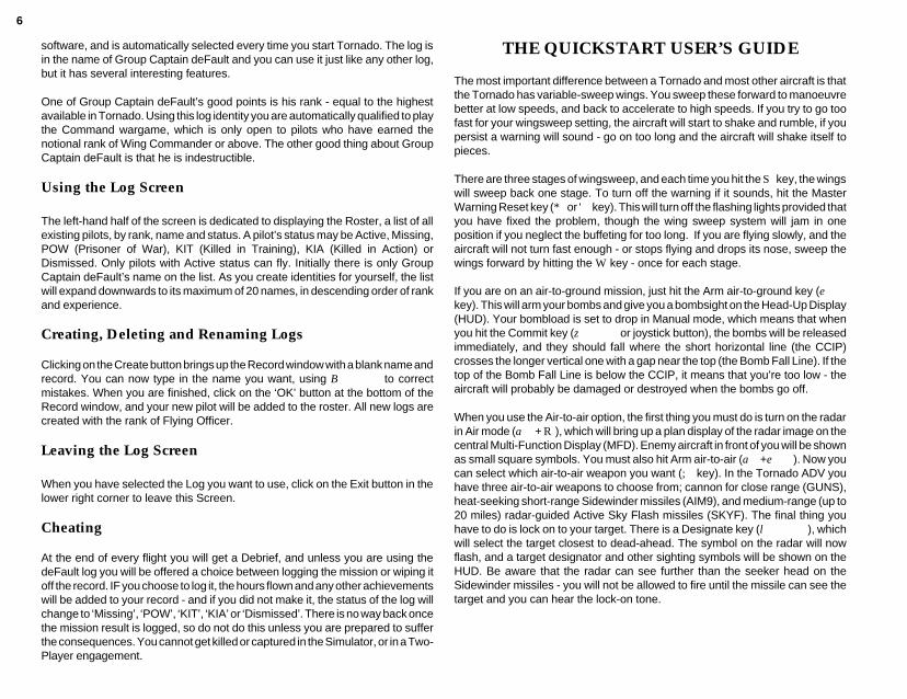
The most important difference between a Tornado and most other aircraft is thatthe Tornado has variable-sweep wings. You sweep these forward to manoeuvrebetter at low speeds, and back to accelerate to high speeds. If you try to go toofast for your wingsweep setting, the aircraft will start to shake and rumble, if youpersist a warning will sound - go on too long and the aircraft will shake itself topieces.
There are three stages of wingsweep, and each time you hit the S key, the wingswill sweep back one stage. To turn off the warning if it sounds, hit the MasterWarning Reset key (* or ' key). This will turn off the flashing lights provided thatyou have fixed the problem, though the wing sweep system will jam in oneposition if you neglect the buffeting for too long. If you are flying slowly, and theaircraft will not turn fast enough - or stops flying and drops its nose, sweep thewings forward by hitting the W key - once for each stage.
If you are on an air-to-ground mission, just hit the Arm air-to-ground key (ekey). This will arm your bombs and give you a bombsight on the Head-Up Display(HUD). Your bombload is set to drop in Manual mode, which means that whenyou hit the Commit key (z or joystick button), the bombs will be releasedimmediately, and they should fall where the short horizontal line (the CCIP)crosses the longer vertical one with a gap near the top (the Bomb Fall Line). If thetop of the Bomb Fall Line is below the CCIP, it means that you’re too low - theaircraft will probably be damaged or destroyed when the bombs go off.
When you use the Air-to-air option, the first thing you must do is turn on the radarin Air mode (a + R), which will bring up a plan display of the radar image on thecentral Multi-Function Display (MFD). Enemy aircraft in front of you will be shownas small square symbols. You must also hit Arm air-to-air (a+e). Now youcan select which air-to-air weapon you want (; key). In the Tornado ADV youhave three air-to-air weapons to choose from; cannon for close range (GUNS),heat-seeking short-range Sidewinder missiles (AIM9), and medium-range (up to20 miles) radar-guided Active Sky Flash missiles (SKYF). The final thing youhave to do is lock on to your target. There is a Designate key (l), whichwill select the target closest to dead-ahead. The symbol on the radar will nowflash, and a target designator and other sighting symbols will be shown on theHUD. Be aware that the radar can see further than the seeker head on theSidewinder missiles - you will not be allowed to fire until the missile can see thetarget and you can hear the lock-on tone.
7
FLIGHT OPTIONS
In the centre of the Main Screen is the large triangular ‘Flight’ icon. Click on thiswith the mouse pointer, and it divides to offer three choices: Simulator, Training,and Combat.
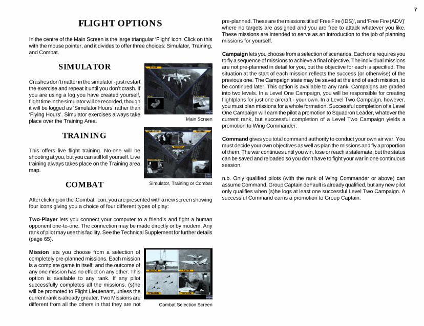
SIMULATOR
Crashes don’t matter in the simulator - just restartthe exercise and repeat it until you don’t crash. Ifyou are using a log you have created yourself,flight time in the simulator will be recorded, thoughit will be logged as ‘Simulator Hours’ rather than‘Flying Hours’. Simulator exercises always takeplace over the Training Area.
TRAINING
This offers live flight training. No-one will beshooting at you, but you can still kill yourself. Livetraining always takes place on the Training areamap.
COMBAT
After clicking on the ‘Combat’ icon, you are presented with a new screen showingfour icons giving you a choice of four different types of play:
Two-Player lets you connect your computer to a friend’s and fight a humanopponent one-to-one. The connection may be made directly or by modem. Anyrank of pilot may use this facility. See the Technical Supplement for further details(page 65).
Mission lets you choose from a selection ofcompletely pre-planned missions. Each missionis a complete game in itself, and the outcome ofany one mission has no effect on any other. Thisoption is available to any rank. If any pilotsuccessfully completes all the missions, (s)hewill be promoted to Flight Lieutenant, unless thecurrent rank is already greater. Two Missions aredifferent from all the others in that they are not
pre-planned. These are the missions titled ‘Free Fire (IDS)’, and ‘Free Fire (ADV)’where no targets are assigned and you are free to attack whatever you like.These missions are intended to serve as an introduction to the job of planningmissions for yourself.
Campaign lets you choose from a selection of scenarios. Each one requires youto fly a sequence of missions to achieve a final objective. The individual missionsare not pre-planned in detail for you, but the objective for each is specified. Thesituation at the start of each mission reflects the success (or otherwise) of theprevious one. The Campaign state may be saved at the end of each mission, tobe continued later. This option is available to any rank. Campaigns are gradedinto two levels. In a Level One Campaign, you will be responsible for creatingflightplans for just one aircraft - your own. In a Level Two Campaign, however,you must plan missions for a whole formation. Successful completion of a LevelOne Campaign will earn the pilot a promotion to Squadron Leader, whatever thecurrent rank, but successful completion of a Level Two Campaign yields apromotion to Wing Commander.
Command gives you total command authority to conduct your own air war. Youmust decide your own objectives as well as plan the missions and fly a proportionof them. The war continues until you win, lose or reach a stalemate, but the statuscan be saved and reloaded so you don’t have to fight your war in one continuoussession.
n.b. Only qualified pilots (with the rank of Wing Commander or above) canassume Command. Group Captain deFault is already qualified, but any new pilotonly qualifies when (s)he logs at least one successful Level Two Campaign. Asuccessful Command earns a promotion to Group Captain.
Main Screen
Simulator, Training or Combat
Combat Selection Screen
8
THE MISSION SELECTION SCREEN
THE SITUATION MENU
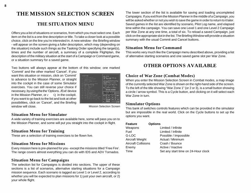
Offers you a list of situations or scenarios, from which you must select one. Eachitem on the list is a one-line description or title. To take a closer look at a possiblechoice, click on the line you’re interested in. A new window - the Briefing window- will appear on the screen giving a fuller description, which may (depending onthe situation) include such things as the Tasking Order specifying the target(s),times and the number of aircraft, a summary of a complete Flightplan, thedescription of the military situation at the start of a Campaign or Command game,or a situation summary for a saved game.
Two buttons will always appear at the bottom of this window; one marked‘Commit’ and the other marked ‘Cancel’. If youwant this situation or mission, click on ‘Commit’to advance to the Mission Planner, or straightinto the cockpit in the case of some Simulatorexercises. You can still reverse your choice ifnecessary, by using the the ‘Options../Exit’ devicein the Mission Planner, or c Q in the cockpit.If you want to go back to the list and look at otherpossibilities, click on ‘Cancel’, and the Briefingwindow will close.
Situation Menu for SimulatorA wide variety of training exercises are available here, some will pass you on tothe Mission Planner, and some will put you straight into the cockpit in flight.
Situation Menu for TrainingThese are a selection of training exercises to be flown live.
Situation Menu for MissionsEvery mission here is pre-planned for you - except the missions titled ‘Free Fire’.The range covers almost everything you can do with IDS and ADV Tornados.
Situation Menu for CampaignsThe selection list for Campaigns is divided into sections. The upper of thesesections is a list of scenarios, alternative starting situations for a Campaignmission sequence. Each scenario is tagged as Level 1 or Level 2, according towhether you will be expected to plan missions for 1) just your own aircraft, or 2)your whole flight.
The lower section of the list is available for saving and loading uncompletedCampaigns. If you exit from the Mission Planner in the middle of a Campaign, youwill be asked whether or not you wish to save the game in order to return to it later.Saved games in the list are identified by scenario, Pilot Log name, and elapsedtime within the campaign. You can save one Level 1 and one Level 2 Campaignper War Zone at any one time, a total of six. To reload a saved Campaign, justclick on the appropriate slot in the list. The Briefing Window will provide a situationsummary with the usual Commit and Cancel buttons.
Situation Menu for CommandThis works very much like the Campaign menu described above, providing a listof alternative starting scenarios and one saved game slot per War Zone.
OTHER OPTIONS AVAILABLE
Choice of War Zone (Combat Modes)When you enter the Mission Selection Screen in Combat modes, a map imageof the currently selected War Zone is shown on the right-hand side of the screen.To the left of the title showing “War Zone 1” (or 2 or 3), is a small button showinga circle / arrow symbol. This is a Cycle button, and clicking on it will select eachWar Zone in turn.
Simulator OptionsThis bank of switches controls features which can be provided in the simulatorbut are impossible in the real world. Click on the Cycle buttons to set up theoptions you want.
Feature OptionsWeapons Limited / InfiniteFuel Limited / InfiniteG-LOC Possible / ImpossibleAircraft Weight Actual / MinimumAircraft Collisions Crash / BounceEnemy Active / InactiveTime Set any start time on 24-Hour clock
Mission Selection Screen
9
THE MISSION PLANNER
SECTION 1 - USING THE MISSIONPLANNER - BASICS
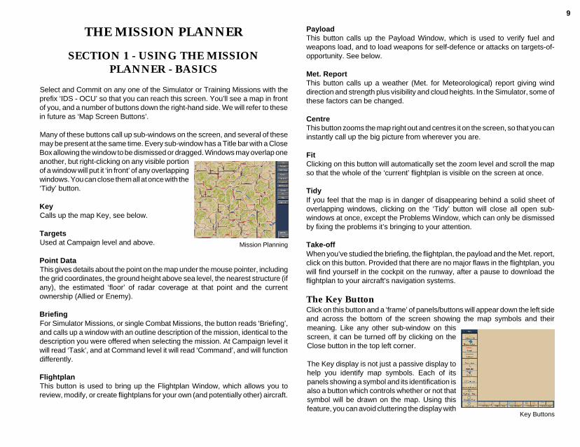
Select and Commit on any one of the Simulator or Training Missions with theprefix ‘IDS - OCU’ so that you can reach this screen. You’ll see a map in frontof you, and a number of buttons down the right-hand side. We will refer to thesein future as ‘Map Screen Buttons’.
Many of these buttons call up sub-windows on the screen, and several of thesemay be present at the same time. Every sub-window has a Title bar with a CloseBox allowing the window to be dismissed or dragged. Windows may overlap oneanother, but right-clicking on any visible portionof a window will put it ‘in front’ of any overlappingwindows. You can close them all at once with the‘Tidy’ button.
KeyCalls up the map Key, see below.
TargetsUsed at Campaign level and above.
Point DataThis gives details about the point on the map under the mouse pointer, includingthe grid coordinates, the ground height above sea level, the nearest structure (ifany), the estimated ‘floor’ of radar coverage at that point and the currentownership (Allied or Enemy).
BriefingFor Simulator Missions, or single Combat Missions, the button reads ‘Briefing’,and calls up a window with an outline description of the mission, identical to thedescription you were offered when selecting the mission. At Campaign level itwill read ‘Task’, and at Command level it will read ‘Command’, and will functiondifferently.
FlightplanThis button is used to bring up the Flightplan Window, which allows you toreview, modify, or create flightplans for your own (and potentially other) aircraft.
Mission Planning
PayloadThis button calls up the Payload Window, which is used to verify fuel andweapons load, and to load weapons for self-defence or attacks on targets-of-opportunity. See below.
Met. ReportThis button calls up a weather (Met. for Meteorological) report giving winddirection and strength plus visibility and cloud heights. In the Simulator, some ofthese factors can be changed.
CentreThis button zooms the map right out and centres it on the screen, so that you caninstantly call up the big picture from wherever you are.
FitClicking on this button will automatically set the zoom level and scroll the mapso that the whole of the ‘current’ flightplan is visible on the screen at once.
TidyIf you feel that the map is in danger of disappearing behind a solid sheet ofoverlapping windows, clicking on the ‘Tidy’ button will close all open sub-windows at once, except the Problems Window, which can only be dismissedby fixing the problems it’s bringing to your attention.
Take-offWhen you’ve studied the briefing, the flightplan, the payload and the Met. report,click on this button. Provided that there are no major flaws in the flightplan, youwill find yourself in the cockpit on the runway, after a pause to download theflightplan to your aircraft’s navigation systems.
The Key ButtonClick on this button and a ‘frame’ of panels/buttons will appear down the left sideand across the bottom of the screen showing the map symbols and their
Key Buttons
meaning. Like any other sub-window on thisscreen, it can be turned off by clicking on theClose button in the top left corner.
The Key display is not just a passive display tohelp you identify map symbols. Each of itspanels showing a symbol and its identification isalso a button which controls whether or not thatsymbol will be drawn on the map. Using thisfeature, you can avoid cluttering the display with

10
symbols you don’t need or want to see. To turn any symbol on or off, just clickon the appropriate panel of the Key window. This can also be used to speed upthe redrawing of the screen if your machine is running more slowly than you like- just turn off everything you think you can do without.
ContoursContour lines are shown for hills at variable intervals above(flat) ground level. Because drawing contours is ademanding task which can reduce a slow computer to acrawl, the vertical distance between contour lines can beset from the Preferences screen (available throughOptions...).
Rivers and LakesSelf-explanatory.
RoadsSelf-explanatory.
RailwaysSelf-explanatory.
Power LinesSelf-explanatory.
StructuresSymbol for buildings, bridges or embankments.
AirfieldsThe runway layouts of the airfields themselves are alwaysshown on the map, with the active runways distinguishedby colour. This button acts only to turn the airfield namelabel on or off.
ILS CoverageIf your aircraft is within the ILS symbol and pointing in thegeneral direction of the runway, your ILS (InstrumentLanding System) will be active, and you may use it eitherto make an automatic approach or to guide a manualapproach.
Flightplan (Current)When a preset mission is loaded, your flightplan will beshown.
Flightplan (Other)When more than one flightplan is shown on the map, theones which you are not currently reviewing or editing will beshown in a different colour.
Category FlagThis symbol is used by the Target Finder facility to highlightall potential targets in a particular category, e.g. roadbridges, control towers, stores dumps etc.
Priority FlagThis symbol is used by the Command Target Priorityfacility to highlight positions which are important targets forone reason or another. This feature is only used at Commandlevel.
The other buttons along the bottom edge of the strip, are ‘split’ buttons. Each isdivided into three areas. These comprise the allied and enemy versions of thesame symbol and the area below containing the legend text. Enemy symbols willnormally appear in orange and allied in blue (check with the Technical Supplementfor your machine if they don’t). Clicking on the symbol areas has just the effectyou would expect - display of the allied or enemy symbols is turned on or offindividually. Clicking below in the text area, however, INVERTS the selectionstate of both allied and enemy symbols at once - it gives you the exact oppositeof what you have at the moment.
AA ThreatAreas known to be covered by AAA or SAMs are shownlike this. The area shown illustrates the maximum effectiverange of the system deployed, and does not take accountof terrain masking or range variation with altitude.
EWR CoverageShows areas within theoretical range of Early WarningRadar stations. Does not take account of terrain masking- but you can get this information from the Flightplan ProfileWindow (see below), or from the Point Data Window.
CAP AreaIndicates a fighter CAP (Combat Air Patrol) area. Enemypositions are estimated, allied positions should be exact.

11
AWACS TrackShows the exact (allied) or estimated (enemy) ‘racetrack’which an AWACS aircraft flies when on station.
Ground ForcesStandard military symbology for an armoured unit, this isplaced at known locations of major ground force formationson the battlefield, in close reserve, or en route to the battlearea.
Moving and Zooming the MapMoving around the map and zooming in or out are done with the mouse,using the RIGHT button. To move a point on the map to the centre of thescreen, just point and click (right) on it. To zoom in or out, click (right)and hold down. A small strip of boxes corresponding to the zoom-levelsavailable will appear under the mouse-pointer, with the pointer on thecurrent zoom level. Keep holding the mouse button down! You may gostraight to any other zoom level you like by simply moving the mousepointer over the appropriate box in the strip and releasing the (right)mouse button.
All about WaypointsThe flightplan for the mission you loaded has already been created for you, andshould be visible on the map when zoomed out. A flightplan is composed ofWaypoints and Legs. Waypoints are fixed points, represented by the symbolsbetween the line sections, and a Leg is simply the path between one Waypointand the next. Legs usually start with a curve and terminate at the next Waypointas straight lines. Waypointscome in several flavours:
Take-off PointThe Take-off Point, which isalways Waypoint A, is obviouslyat the airfield from which youtake off.
Turning PointsTurning Points are simplyplaces where you changecourse - these are by far themost common type.
ZoomControl
diagram 2
Initial PointsInitial Points are the Turning Points from which you start the attack run on aground target.
TargetsTargets are labelled with the letters X, Y and theoretically Z, for the first, secondand (most unlikely) third planned targets of a mission.
CAP StartThis is used to set up a Combat Air Patrol station for ADV missions. The relativepositions of this point and the next waypoint (the CAP End point) define an oval‘racetrack’ for your aircraft to patrol while waiting to intercept incoming enemyaircraft.
CAP EndSee CAP Start, above. ADV flightplans only.
Approach PointThe Approach Point should be placed at the end of one ILS beam of the airfieldat which you intend to land - you can make the ILS beam coverage visible on themap using the Key.
PositionCoordinates are displayed in the title bar of a waypoint window.
Head/Tail WindOnly Take-off and Approach Points have this attribute.
Cross-windOnly for Take-off and Approach Points. This is the strength in knots of thecomponent of the wind which is blowing across the runway as you take off or land.
TimeAll waypoints show a Time and Time Status. For a Take-off point, this is the take-off time. For all other waypoints it is the time at which you expect, or plan, to passor attack this point. The Status will show ‘Free’, ‘Fixed’ or ‘Bound’.
AltitudeEvery Waypoint type except Take-off Points will also have an altitude/ride height,and an AFDS Altitude Authority attribute. If the Altitude Authority is set at ‘AltitudeHold’, the AFDS system will fly the leg to this waypoint at the given BAROMETRICaltitude, i.e. height above sea level. If the Altitude Authority setting is ‘Ride Height’,the AFDS system will fly the leg Terrain Following at the Ride Height given, i.e.clearance above the ground beneath the aircraft.
12
SpeedAll waypoint types except Take-off show a Speed and Speed Status. This is theaverage speed at which it is necessary to fly the leg approaching this waypointin order to arrive at the Time shown.
TargetTarget waypoints only. Shown on the waypoint window Title bar next to the mapcoordinates. Describes the target, e.g. road bridge, HAS, runway etc.
Package data: WeaponDeliverySalvoMinimum recommended delivery height.
Target waypoints only. These parameters specify the Package of weapons to beused in attacking this target, and how the Package is to be delivered.
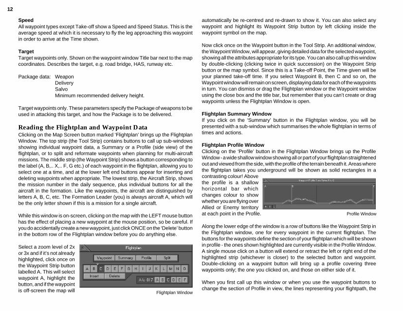
Reading the Flightplan and Waypoint DataClicking on the Map Screen button marked ‘Flightplan’ brings up the FlightplanWindow. The top strip (the Tool Strip) contains buttons to call up sub-windowsshowing individual waypoint data, a Summary or a Profile (side view) of theflightplan, or to split and reformate waypoints when planning for multi-aircraftmissions. The middle strip (the Waypoint Strip) shows a button corresponding tothe label (A, B,.. X,.. F, G etc.) of each waypoint in the flightplan, allowing you toselect one at a time, and at the lower left end buttons appear for inserting anddeleting waypoints when appropriate. The lowest strip, the Aircraft Strip, showsthe mission number in the daily sequence, plus individual buttons for all theaircraft in the formation. Like the waypoints, the aircraft are distinguished byletters A, B, C, etc. The Formation Leader (you) is always aircraft A, which willbe the only letter shown if this is a mission for a single aircraft.
While this window is on-screen, clicking on the map with the LEFT mouse buttonhas the effect of placing a new waypoint at the mouse position, so be careful. Ifyou do accidentally create a new waypoint, just click ONCE on the ‘Delete’ buttonin the bottom row of the Flightplan window before you do anything else.
Select a zoom level of 2xor 3x and if it’s not alreadyhighlighted, click once onthe Waypoint Strip buttonlabelled A. This will selectwaypoint A, highlight thebutton, and if the waypointis off-screen the map will Flightplan Window
automatically be re-centred and re-drawn to show it. You can also select anywaypoint and highlight its Waypoint Strip button by left clicking inside thewaypoint symbol on the map.
Now click once on the Waypoint button in the Tool Strip. An additional window,the Waypoint Window, will appear, giving detailed data for the selected waypoint,showing all the attributes appropriate for its type. You can also call up this windowby double-clicking (clicking twice in quick succession) on the Waypoint Stripbutton or the map symbol. Since this is a Take-off Point, the Time given will beyour planned take-off time. If you select Waypoint B, then C and so on, theWaypoint window will remain on screen, displaying data for each of the waypointsin turn. You can dismiss or drag the Flightplan window or the Waypoint windowusing the close box and the title bar, but remember that you can’t create or dragwaypoints unless the Flightplan Window is open.
Flightplan Summary WindowIf you click on the ‘Summary’ button in the Flightplan window, you will bepresented with a sub-window which summarises the whole flightplan in terms oftimes and actions.
Flightplan Profile WindowClicking on the ‘Profile’ button in the Flightplan Window brings up the ProfileWindow - a wide shallow window showing all or part of your flightplan straightenedout and viewed from the side, with the profile of the terrain beneath it. Areas wherethe flightplan takes you underground will be shown as solid rectangles in acontrasting colour! Abovethe profile is a shallowhorizontal bar whichchanges colour to showwhether you are flying overAllied or Enemy territoryat each point in the Profile.
Along the lower edge of the window is a row of buttons like the Waypoint Strip inthe Flightplan window, one for every waypoint in the current flightplan. Thebuttons for the waypoints define the section of your flightplan which will be shownin profile - the ones shown highlighted are currently visible in the Profile Window.A single mouse click on a button will extend or retract the left or right end of thehighlighted strip (whichever is closer) to the selected button and waypoint.Double-clicking on a waypoint button will bring up a profile covering threewaypoints only; the one you clicked on, and those on either side of it.
When you first call up this window or when you use the waypoint buttons tochange the section of Profile in view, the lines representing your flightpath, the
Profile Window

13
terrain below and the ‘ownership’ of that terrain will be drawn quite rapidly. Oncethese are complete, the flightplan section will be checked against known AAThreats, and vertical hatching will be shown wherever it intersects a threat circle.After this is done, another (usually broken) line will appear on the Profile display,drawn more slowly from left to right.This shows, for every point along the Profilesection, the altitude above which you will probably be visible to known enemyground radars - so obviously your flightplan should keep you below it whereverpossible. The reason why the line appears slowly is quite simple - the line-of-sightcalculations needed to show this data take a LOT of processing power, but theyare performed as a ‘background task’ and will not prevent you from moving aboutthe map, zooming in or out, dragging windows or performing any other function,though if you change the flightplan by placing, dragging or deleting waypoints theprofile will need to redraw from scratch.
Mission Rehearsal using Explore ModeIf you wish to explore a particular area, just right-click on that point to centre it onthe Mission Planner map before entering Explore Mode.
Met. ReportBefore taking off, click on the Map Screen Button marked ‘Met. Report’. This willopen a window to give you a meteorological report, telling you about windstrength/direction and visibility conditions.
diagram 3
WindShows bearing in degrees (the direction the wind is blowing FROM).
VisibilityFour visibility conditions are possible; Light Cloud Only, Overcast, Fog and ThickFog. Overcast is a thick continuous layer of cloud.
Effects of Weather on the Mission
WindThis will mainly affect the length of your take-off and landing run, and the difficultyof your approach.
CloudObviously you can’t see through thick cloud, but neither can an infra-red sensoror most lasers. This may degrade or utterly destroy the performance of heat-seeking missiles, but it will also defeat your TIALD (Thermal Imaging and LaserDesignator) cameras.
The Payload WindowThe Payload window can be called up at any time by clicking on the Map ScreenButton marked ‘Payload’.
The buttons for weapon packages loaded for planned attacks will show ‘X’, ‘Y’ or‘Z’. The contents of these packages cannot be changed except by changing themission plan. If a package is empty or loaded for targets-of-opportunity, thebutton will show a dash (“-”). The ‘Other’ button displays external stores whichare not part of any weaponPackage, like drop tanks,AIM9Ls and defensivepods, and allows you toload or unload them.
ADV aircraft do not carryground attack weapons,but can carry Sky Flash,which the IDS cannot, sothe Payload screen for anADV mission will show farfewer options, and thereis no need to distinguishbetween packages.
Payload Window
14
Stores (weapons or other external loads) are listed down the left-hand side of thePayload window, with a line running horizontally to the right from each beneaththe aircraft diagram.
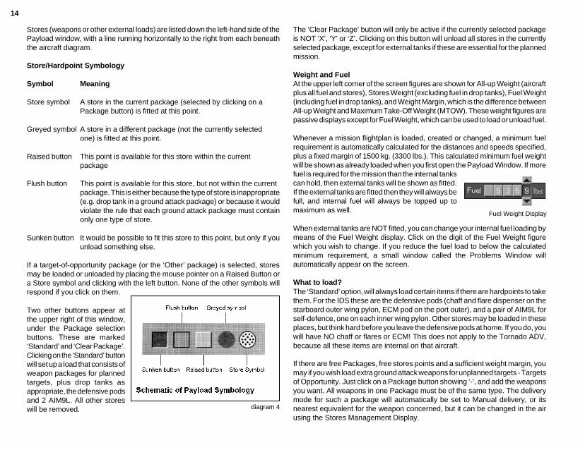
Store/Hardpoint Symbology
Symbol Meaning
Store symbol A store in the current package (selected by clicking on aPackage button) is fitted at this point.
Greyed symbol A store in a different package (not the currently selectedone) is fitted at this point.
Raised button This point is available for this store within the currentpackage
Flush button This point is available for this store, but not within the currentpackage. This is either because the type of store is inappropriate(e.g. drop tank in a ground attack package) or because it wouldviolate the rule that each ground attack package must containonly one type of store.
Sunken button It would be possible to fit this store to this point, but only if youunload something else.
If a target-of-opportunity package (or the ‘Other’ package) is selected, storesmay be loaded or unloaded by placing the mouse pointer on a Raised Button ora Store symbol and clicking with the left button. None of the other symbols willrespond if you click on them.
Two other buttons appear atthe upper right of this window,under the Package selectionbuttons. These are marked‘Standard’ and ‘Clear Package’.Clicking on the ‘Standard’ buttonwill set up a load that consists ofweapon packages for plannedtargets, plus drop tanks asappropriate, the defensive podsand 2 AIM9L. All other storeswill be removed. diagram 4
The ‘Clear Package’ button will only be active if the currently selected packageis NOT ‘X’, ‘Y’ or ‘Z’. Clicking on this button will unload all stores in the currentlyselected package, except for external tanks if these are essential for the plannedmission.
Weight and FuelAt the upper left corner of the screen figures are shown for All-up Weight (aircraftplus all fuel and stores), Stores Weight (excluding fuel in drop tanks), Fuel Weight(including fuel in drop tanks), and Weight Margin, which is the difference betweenAll-up Weight and Maximum Take-Off Weight (MTOW). These weight figures arepassive displays except for Fuel Weight, which can be used to load or unload fuel.
Whenever a mission flightplan is loaded, created or changed, a minimum fuelrequirement is automatically calculated for the distances and speeds specified,plus a fixed margin of 1500 kg. (3300 lbs.). This calculated minimum fuel weightwill be shown as already loaded when you first open the Payload Window. If morefuel is required for the mission than the internal tankscan hold, then external tanks will be shown as fitted.If the external tanks are fitted then they will always befull, and internal fuel will always be topped up tomaximum as well.
When external tanks are NOT fitted, you can change your internal fuel loading bymeans of the Fuel Weight display. Click on the digit of the Fuel Weight figurewhich you wish to change. If you reduce the fuel load to below the calculatedminimum requirement, a small window called the Problems Window willautomatically appear on the screen.
What to load?The ‘Standard’ option, will always load certain items if there are hardpoints to takethem. For the IDS these are the defensive pods (chaff and flare dispenser on thestarboard outer wing pylon, ECM pod on the port outer), and a pair of AIM9L forself-defence, one on each inner wing pylon. Other stores may be loaded in theseplaces, but think hard before you leave the defensive pods at home. If you do, youwill have NO chaff or flares or ECM! This does not apply to the Tornado ADV,because all these items are internal on that aircraft.
If there are free Packages, free stores points and a sufficient weight margin, youmay if you wish load extra ground attack weapons for unplanned targets - Targetsof Opportunity. Just click on a Package button showing ‘-’, and add the weaponsyou want. All weapons in one Package must be of the same type. The deliverymode for such a package will automatically be set to Manual delivery, or itsnearest equivalent for the weapon concerned, but it can be changed in the airusing the Stores Management Display.
Fuel Weight Display

15
Starting the MissionWhen you are satisfied that you have absorbed all the necessary information, andthat the aircraft is suitably loaded for the mission, you can click on the Map ScreenButton labelled ‘Take-off’.
SECTION 2 - PLANNING YOUR OWNMISSIONS
2a - ‘FREE FIRE’ and LEVEL 1 CAMPAIGNSWhen you arrive at the Mission Planner for a ‘Free Fire’ mission there will be nopreset mission plan at all, and it’s up to you to select a target, a patrol station orother objective and create a flightplan.
The Campaign option is the next step up, providing a connected series ofmissions set in a military situation which evolves over time. If you choose‘Campaign’ on the ‘Combat ‘ screen, and one of the Level 1 Campaign scenariosyou will see a bare outline of a mission which simply specifies an objective, ratherthan a complete flightplan. This outline is your Task for the next mission, and youmust do all the detailed planning, then fly it. When (and if) you return from thatmission your commander will present you with a new Task to plan and fly. TheCampaign will last for as many missions as it takes to accomplish the Campaignobjectives, or to lose the war, or until a stalemate is reached. When you need abreak, you can exit from the Mission Planner to the Mission Selection Screen andsave the current situation to reload and continue later.
Turning a Task into a FlightplanWhen you select a Campaign scenario on the Mission Selection Screen, insteadof the Briefing you would expect for a single mission you will see a summarydescribing the military situation at the time the Campaign starts. When youCommit and move to the Mission Planner, two differences should be seen: a)there is a flightplan laid out, but it’s just a skeleton, and b) the Map Screen Buttonwhich used to say ‘Briefing’ is now titled ‘Task’. Click on the Task button to seethe Air Tasking Message - these are your orders.
Problems, Warnings and ErrorsWhen you first see the skeleton flightplan of a new Task on the Mission Plannermap, you’ll often notice a small window without a close box, titled ‘Problems’. Thisappears because the Task outline as it stands is not a viable flightplan, and theplanning support systems are automatically alerting you to the fact.
The planning systems apply a set of rules to any flightplan to detect unreasonablesituations such as unflyable course changes, impossible or improbable timings
and speeds, or Initial Points too close to the target. When a flightplan bends orbreaks these rules, the Problems window will automatically appear with a list ofmessages. These messages will start with either 'ERROR' for a problem whichmust be fixed before you take off, or 'WARNING' when the problem is not soserious as to completely invalidate the flightplan.
Setting and Moving WaypointsIf you are planning a ‘Free Fire’ mission there will be only one waypoint on the mapwhen you enter the Mission Planner - the Take-off Point, where you and youraircraft are based. You will have to lay down all the other waypoints for the missionyourself. If you are starting a Campaign, an IDS Task outline will usually presetTarget Waypoint(s), and an ADV Task will usually preset a CAP point, dependingon the nature of the mission, plus an Approach Point. You will generally createyour flightplan by inserting extra waypoints between the ones you are given, andthen dragging them into position.
In order to start placing or moving waypoints you must first click on the MapScreen Button labelled Flightplan, thus opening the Flightplan window. Rememberthat a flightplan may have up to 15 waypoints, but no more. When the limit isreached, the system will refuse to create any more.
Placing WaypointsClicking anywhere on the map with the LEFT mouse button will place a newwaypoint at that point, adding it to the end of your current flightplan. The newwaypoint will be a Turning Point by default unless it is placed in the ILS coverageof an allied airfield, in which case it will be created as an Approach Point.
Dragging WaypointsPlace the mouse pointer crosshair on the symbol of the waypoint you wish tomove and hold down the LEFTmouse button. While you holdthe button down you may dragthe waypoint about the mapby moving the mouse. ‘RubberLines’ will be drawn to showthe new legs to and from thewaypoint affected. When yourelease the mouse button thewaypoint is ‘dropped’ in itsnew position, and the legs toand from will be redrawn,together with the curve of theturn following the waypoint.
diagram 5

16
Selecting WaypointsA waypoint must be selected before certain operations can be performed uponit. Waypoints may be selected either by clicking on the appropriate letter in theFlightplan Window, or by clicking inside the appropriate waypoint symbol on themap.
Deleting WaypointsThe Delete button is not shown in the Waypoint Strip of the Flightplan Windowunless it’s permissible to delete the selected waypoint. Waypoint A can never bedeleted. When working with a flightplan for multiple aircraft, only formationwaypoints may be deleted.
Inserting WaypointsThe Insert button is not shown in the Waypoint Strip of the Flightplan Windowunless it’s possible to insert a new waypoint BEFORE the currently selected one.New waypoints are inserted halfway between existing ones, and must bedragged to their desired positions. Waypoints cannot be inserted if all 15 availablewaypoints are already used. When working with a flightplan for multiple aircraft,insertions can only be made in legs common to all aircraft in the formation.
Turning CirclesThe radius of the curve is governed by the Speed set for the adjacent waypointand the control authority of the AFDS system: the faster the speed, the wider theturn.
For this reason, if you wish to control the precise direction of more than one legin a flightplan (e.g. for a JP.233 attack run or an approach for landing) it is bestto lay out all the waypoints first, then precisely place the Target Waypoint(s),select weapon(s) and delivery mode(s), set any fixed Speeds (and/or Times) andonly then to work through the flightplan in order from start to finish draggingwaypoints to set direction, sothat changes rippling forwardaffect only the legs which youhave not yet adjusted.
Two kinds of problem can arisewhen you place two waypointstoo close together. The first ofthese problems can affect anypair of waypoints, and happenswhen the second waypoint isINSIDE the diameter of theturning circle curve from thefirst. Diagram 6 shows that this
diagram 6
means it is quite impossible for the aircraft ever to reach the second waypoint byturning towards it - instead it will circle until you use the Next Waypoint key to skipthe offending waypoint.
The second type of problemaffects only Initial Points andTargets. The planning systemcalculates how far back fromthe target the weapon will bereleased, and demands that youmust have time to line up on astraight attack run before youreach the release point (or thepull-up point for a Loft attack).
Creating and Placing a Target Waypoint (IDS only)Assuming that you know what type of target you want to hit and roughly whereit is, centre the map on the approximate position and place a standard TurningPoint waypoint there.
Click on the Map Screen Button labelled ‘Targets’, which calls up a windowshowing two lists. Click on an item in the left list to select a category of target(Military, Transport etc.). The right list will change to display a list of individualtypes of target in the selected category (e.g. Hangar, Hardened Munitions Storeetc.). Click on the type which describes your target. Every target of that type onthe map will now be marked by the Category Flag symbol, helping you pick outyour intended target from other buildings in the same area. Category Flagsymbols will be shown on the map while the Target Finder window is open,regardless of whether or notCategory Flags are turned on inthe Key. When you close theTarget Finder window, theCategory Flag symbols willdisappear unless they areenabled by the Key.
Drag your intended Targetwaypoint (still a Turning Pointat this stage) to the target anddrop it there. Now call up theWaypoint Window. At the leftend of the line displaying thewaypoint Type is a buttonshowing a small circular symbol.
diagram 7
Target Finder Window

17
Click once on the Type Cycle button. The waypoint Type changes from TurningPoint to Target, the label changes to X, Y or Z, the Waypoint Window expandsand acquires the extra displays necessary to define the weapon Package, andthe waypoint symbol on the map changes shape and ‘snaps’ to the intendedtarget. Whenever you change a Turning Point into a Target waypoint, thewaypoint will snap to the exact position of the nearest object. If Category Flagdisplay is enabled, it will snap to the nearest flagged object. The 'snapping' featurecan be disabled by holding down the a key while dragging the Target Waypoint.The Turning Point before the Target will automatically change to an Initial Point.
The planning systems will also select a default weapon Package based on thetype of Target, but if you like you may change this. To select a Weapon type justclick on the desired button in the Weapon display. If the weapon type has morethan one possible delivery mode you may choose from the available options byclicking repeatedly on the Cycle button at the left of the Delivery display. At theright of the Delivery display is the Safety Height Button; clicking on this sets thewaypoint Altitude to the minimum safe height. Below this is the Salvo Size display,showing how many weapons there are in the Package. The Cycle button besideit can be used to select a size of 1, 2 or 4 weapons, depending on the type. Thebutton to the right shows the recommended salvo size for the recommendedweapon, and clicking on this will set that figure.
Setting up a CAP Station (ADV only)The ‘typical’ ADV Combat Air Patrol mission involves taking off, flying to a givenposition and altitude, and then flying round and round in a ‘racetrack’ patternwaiting to intercept enemy aircraft. In order to set up a CAP mission, create askeleton flightplan (if it’s not provided) and place a Turning point roughly whereyou want each end of your racetrack pattern to be. Space them fairly well apartto start with. Now select the first of these two waypoints and call up the WaypointWindow. Click on the Cycle button for the waypoint Type, and it will change to‘CAP Start’. This will automatically convert the next Turning Point into a ‘CAPEnd’, and you should see the leg between the two change into a circuit withrounded ends - your CAP pattern.
AltitudeFor normal air-to-groundoperations the AltitudeAuthority Mode shows‘Ride Height’ and the valueset is 200 (feet), so that ifthe aircraft is under AFDSTrack mode control it willfly these legs terrain-following at 200 feet.
Clicking on the Cycle button at the left of the display changes the mode from ‘RideHeight’ to ‘Altitude Hold’ or vice versa. If you have selected ‘Ride Height’ and youwant to change the actual height value, click on the button showing the valueitself. If you select ‘Altitude Hold’ as the Altitude Authority Mode, each digit of thealtitude figure will appear as a separate button. Clicking on any of these will callup arrow buttons to change one digit at a time up or down. The planning systemwill check your altitude on the Attack run against the Minimum Safe Height forweapon release, and issue a WARNING if it’s set too low.
Times and SpeedsThe system uses two default values for speed; 420 knots as a standard cruise,and 550 knots as a standard speed for attack runs; and it will normally calculatewaypoint times using these values. If you wish, however, you may set anyfeasible speed value you want for any leg, and if you do the Speed status willchange from ‘Free’ to ‘Fixed’. ‘Fixed’ status means that the planning systems willjuggle other times and speeds which have ‘Free’ status as much as necessaryin order to ensure that you can fly your attack run at this speed and still maintainyour timetable.
Time and Speed status can be changed using the Cycle buttons at the left of theirrespective display lines, but it would be more common to change the actual Timeor Speed value first, which will automatically change a ‘Free’ status to ‘Fixed’.
Time and Speed ProblemsA waypoint’s Time is theplanned time of arrival (and/ordeparture) at that waypoint. TheSpeed is the average speedover the preceding leg of theflightplan which will get youthere at that time. Speed at awaypoint is also used tocalculate the radius of the turnonto the next leg, so wait tillyou’re on the straight run to thenext waypoint before you accelerate or decelerate.
Let’s assume that we have a target (X) ten nautical miles away from its Initial Point(call it D). The Time at X is 12:00:00 Fixed, Speed is 600 Knots Fixed. If you wereto look at the Waypoint data for D, you’d find the Time at D showing as 11:59:00Bound, and you would be unable to change status or value directly, though theTime would change if you dragged D to a different position.
Target Waypoint Window
diagram 8
18
The Speed of 600 knots for the leg D-X dictates exactly how long it should taketo fly the distance from D to X: at 600 knots you’ll cover the 10 nautical miles fromD to X in 1 minute. That means that you MUST pass D at 11:59:00 - no otheranswer is possible unless you start allowing for variable speeds over the leg.That’s why the Time status at D is ‘Bound’.
There is another variant of the same problem. If you Fix the Times of two adjacentwaypoints, the Speed for the leg between them (the one given for the secondwaypoint) becomes Bound; it is dictated absolutely by the Times and the distancebetween the waypoints.
The best way to avoid creating problems for yourself is to Fix Times and Speedsonly when necessary - and most of the time it’s not necessary. Under normalcircumstances the only Time in a mission which needs to be Fixed is the Time-On-Target, and the only legs where Speed need be fixed are legs where you haveno choice but to cross defended zones.
SECTION 2B - LEVEL TWO CAMPAIGNS
At this level, you are responsible for creating flightplans for your whole formationof Tornados and setting up coordinated attacks. A Task at this level will normallyprescribe an attack on a large enemy installation - an airfield, for example - assigntargets to each aircraft and specify a Time-on-Target. It will be your responsibilityto set up the individual attacks and their precise timing. Here is a list of basicprinciples for achieving a successful coordinated attack:
1: Concentration in Time. If your entire attack is compressed into the space of afew seconds with no advance warning you may be gone almost before the enemyhas started shooting.
2: Dispersion in space. If you send the aircraft in from many different directionsat the same time, you divide the enemy’s fire and reduce his chances of scoringa hit.
3: Go for the defences first. And do it from as far away as possible.
4: Try to avoid blowing each other up. Don’t set up the attacks so that one aircraftflies through the debris hemisphere of another’s bombs. Assume that a 1000 lb.bomb has a debris hemisphere of 1000-feet (305 m) radius, and that a separationof 200 feet (61 m) is adequate for all other weapons. You can achieve separationby varying approach direction, altitude or Time-On-Target (but only within acouple of seconds either way - see next point).
5: Be on time.
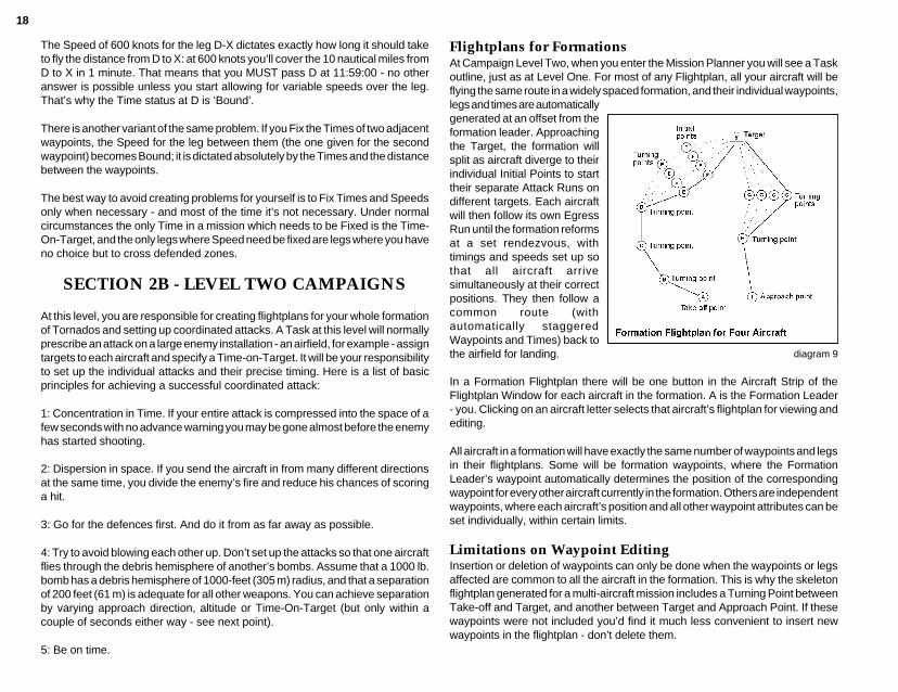
Flightplans for FormationsAt Campaign Level Two, when you enter the Mission Planner you will see a Taskoutline, just as at Level One. For most of any Flightplan, all your aircraft will beflying the same route in a widely spaced formation, and their individual waypoints,legs and times are automaticallygenerated at an offset from theformation leader. Approachingthe Target, the formation willsplit as aircraft diverge to theirindividual Initial Points to starttheir separate Attack Runs ondifferent targets. Each aircraftwill then follow its own EgressRun until the formation reformsat a set rendezvous, withtimings and speeds set up sothat all aircraft arrivesimultaneously at their correctpositions. They then follow acommon route (withautomatically staggeredWaypoints and Times) back tothe airfield for landing.
In a Formation Flightplan there will be one button in the Aircraft Strip of theFlightplan Window for each aircraft in the formation. A is the Formation Leader- you. Clicking on an aircraft letter selects that aircraft’s flightplan for viewing andediting.
All aircraft in a formation will have exactly the same number of waypoints and legsin their flightplans. Some will be formation waypoints, where the FormationLeader’s waypoint automatically determines the position of the correspondingwaypoint for every other aircraft currently in the formation. Others are independentwaypoints, where each aircraft’s position and all other waypoint attributes can beset individually, within certain limits.
Limitations on Waypoint EditingInsertion or deletion of waypoints can only be done when the waypoints or legsaffected are common to all the aircraft in the formation. This is why the skeletonflightplan generated for a multi-aircraft mission includes a Turning Point betweenTake-off and Target, and another between Target and Approach Point. If thesewaypoints were not included you’d find it much less convenient to insert newwaypoints in the flightplan - don’t delete them.
diagram 9
19
Split and FormateThe rightmost button in the Tool Strip of the Flightplan Window will show twoalternative legends according to the nature of the currently selected waypoint -‘Split’ or ‘Formate’. When the selected waypoint is a formation waypoint, it willshow ‘Split’, and clicking on the button will make this into an individual waypointfor all aircraft in the formation. You’ll be able to see the effect of this on the map,since the individual waypoints will automatically spread out from the originalposition. Each independent waypoint will be of the same Type (Turning Point orTarget) as the formation waypoint which was split to produce them. All otherwaypoint attributes except position will also be inherited.
You can now use the buttons in the Aircraft Strip of the Flightplan window to selectthe flightplan of any aircraft in the formation. Each aircraft’s independentwaypoints may be dragged about or edited in any way you like, provided that it’sphysically possible for each aircraft to fly its independent track and rejoin theformation on time at the next formation waypoint. If you’re asking for theimprobable or the impossible, you’ll see a WARNING or ERROR in the Problemswindow.
When the selected waypoint is an independent waypoint, the button will show‘Formate’. Let’s say that your currently selected waypoint is D, an independentwaypoint, and you’ve selected aircraft B’s flightplan. Clicking on ‘Formate’ willturn D into a formation waypoint at the same position. The formation waypointattributes will be inherited from the original independent waypoint.
The skeleton flightplan automatically generated from the Tasking Message willgive every aircraft an identical Time-On-Target. If the targets are closely spaced,this would result in your aircraft blowing one another up. As we suggested above,you will need to adjust direction, altitude and time of attack to ensure that thisdoesn’t happen.
SECTION 3 - COMMAND LEVEL
At this level, you have complete command authority. At Campaign level you hadthe job of turning a Task into a flightplan; at Command level you create the Taskas well. You will need to exercise all the skills you have already learnt in missionplanning and flying, but in addition you will need to make the all-importantdecisions about what targets to strike, and how to divide your resources.
In order to select ‘Command’ on the Flight Options page, the pilot whose log iscurrently selected must be Command-qualified, holding the rank of WingCommander or Group Captain. As with the ‘Campaign’ option, the MissionSelection Screen for Command level presents a selection of starting scenarios,
and allows you to select any one of the three War Zones. In addition, you can saveone Command game per War Zone to reload and continue later.
The Mission Planner in Command ModeWhen you commit to a Command scenario, you will see that the Mission PlanningScreen looks exactly as before except that the Map Screen Button which usedto read ‘Briefing’ or ‘Task’ is now titled ‘Command’. Also, if you click on theFlightplan button straight away, the Flightplan window will not appear. This isbecause you haven’t yet created any Tasks, which can only be done by callingup the Command Window.
The Command WindowThis window allows you to review intelligence data to help in selecting yourobjectives, and then issue the orders to accomplish them. It contains a strip ofbuttons at the top, and its lower portion (the Priority Target Finder) closelyresembles the Target Finder called up by the Targets button.
SituationThis calls up the Situation Report window, which provides a summary of theoverall military situation.
Air PowerThis button calls up the Air Power window, which summarises the location, natureand strength of air force units on both sides.
RelocateClick on this button to call up the Relocation window, which shows buttonscorresponding to all serviceable Allied airfields.
Your current base airfield will be highlighted - to shift your Tornados to anotherairfield, just click on the appropriate button. When you use this facility to shift yourbase, all flightplans for the tasks you generate in this round should be set up forlanding at the new base. Tornados landing elsewhere (including the old base) willincur the normal time-penalty for ferry flights.
TaskingThe Tasking window called up by this button allows you to allocate Tasks toformations of Tornados, or single aircraft. Once you have created a Task, you cancreate the flightplan(s) for that Task. The window shows the number of Tornadosavailable for operations, both IDS and ADV. When you first call up this windowin each round, one line will be displayed showing a Mission number followed bya button showing the type of Tornado assigned, with a Cycle button beside it. This
20
button will initially show ‘None’, but by clicking on the Cycle button it may bechanged to read ‘IDS’ or ‘ADV’, depending upon availability of the type.
When the type is changed to something other than ‘None’, two further buttonsappear to the right, each with a Cycle button beside it. The first shows the numberof aircraft assigned to the formation, defaulting to 1. The associated Cycle buttoncan be used to change the number of aircraft between 1 and the maximumavailable, and as this figure is changed the availability figure will fluctuateaccordingly. You can’t change the figure to 0, but the same effect can be achievedby selecting a Type of ‘None’. The rightmost button can be used to display adescription of the mission type as a reminder of your intentions.
When you create a Task by assigning aircraft to it, a mission number for a furtherTask will appear on the line below, up to a maximum of four Tasks or until allavailable aircraft are assigned. You may only modify aircraft assignments for thelatest Task in the list - if you change your mind and want to modify tasks earlierin the list, you must delete all later tasks by setting their aircraft types to ‘None’,in order from the last backwards. You should also bear in mind that you willALWAYS fly aircraft A in the first Task in the list. Once a Task has been createdby assigning aircraft to it, its flightplan may also be created in the normal way bycalling up the Flightplan window. You can select which Task’s flightplan to editby clicking on the appropriate mission number in the Tasking window.
Priority Target FinderThis system gives you easy access to processed intelligence data, showing youwhich facilities are most important to the enemy’s war effort. Which category oftarget you set out to strike should be determined by the broader view you gainfrom the Situation Report and Air Power windows. The quantity and quality ofintelligence available will govern the quantity and quality of the evaluationsprovided by the Priority Target Finder.
Like the Target Finder, the Priority Target Finder shows two columns; the leftbeing used to select a broad class of targets, and the right to display a completelist of all the individual items in this class. The items on the right are each markedwith one of three symbols, a tick, a cross or a question mark. A tick indicates thatintelligence can offer you targets of this type, whereas a cross tells you that noinformation is available - better intelligence is needed. A question mark indicatesthat intelligence is still being evaluated - targets aren’t available yet, but they willbe sometime soon. When such items are ready, the symbol will change from aquestion mark to a tick.
The Priority Flag markers work just like the Category Flags, they are automaticallyenabled when this window is open, but when it’s closed you can use the Keywindow to control whether or not they are displayed.
Class: CommandThis class selects enemy headquarters, where known, and flags the mostimportant. Destroying an HQ may have serious effects on the coordination ofenemy forces and the efficiency of the enemy supply system.
Command: Rear HQThese are permanent hardened facilities normally well behind the line of battleand very well defended.
Command: Field HQThese are the headquarters of force commanders close to the front line.
Class: CommsCommunications targets are important in themselves, and vital for the potentialeffect on intelligence.
Comms: Main NodeThese are permanent facilities, easily recognisable by the microwave relay toweron the site.
Comms: Field RelayThese are temporary camouflaged installations providing secure communicationsbetween the battlefield rear area and the main comm. net.
Class: LogisticsThis class of targets covers the enemy supply system - perhaps the mostimportant class of all. As a result of this, all roads and railways leading towardsthe battlefield will be vital channels of supply - if you can cut these channels theenemy’s fighting power will be very seriously reduced.
Logistics: POL InstallationsPOL is the standard military abbreviation for Petrol, Oil, Lubricants. If stocks ofthese are seriously depleted, all vehicles from trucks through tanks to aircraft willbe seriously affected, though airfields normally have large stocks on site in well-protected underground tankage.
Logistics: Main DepotsThese are main centres of supply - major stockpiles holding huge quantities ofeverything needed to supply armed forces.
Logistics: Forward DumpsThese are small, dispersed, camouflaged stockpiles which supply the needs oflocal forces and are replenished in turn from the major stockpiles.
21
Logistics: Choke PointsChoke points are places where transport routes can be cut with maximum effectand efficiency - in Tornado, all choke points are bridges.
Class: PoliticsThis is a miscellaneous category for targets which are not strictly military.
Politics: Power StationDepriving the enemy population of power may have a significant effect on morale- provided that it is already depressed.
Politics: SCUD LaunchersThe classical political distraction target, familiar to all Gulf War fans. If you decideto go looking for them, don’t expect to find them exactly where intelligence saidthey were.
Politics: DecapitationA Decapitation (beheading) strike is designed to take out your enemy’s politicalleadership, on the assumption that their successors will either be more willing totalk, or will paralyse the military command structure by fighting among themselvesfor power.
Politics: NBC CapabilityNBC is for Nuclear/Biological/Chemical weapons. If this category of target isoffered, they represent research and manufacturing sites rather than stockpiles.
Class: BattlefieldThese targets represent places where you might directly influence the land battle.
Battlefield: Direct SupportThese are Close Air Support targets - enemy forces in contact with allied forces.
Battlefield: ReservesAs the name suggests, these are the locations of enemy armoured units inreserve.
Battlefield: Repair CentreIf you can knock out or seriously damage these major repair centres it can havea devastating effect on enemy ground forces, because repair of anything worsethan minor breakdowns and battle damage will slow down severely or stopaltogether.
Class: Counter AirThese are all types of target which are important to the air war in different ways.
Counter Air: AirfieldsIf Allied intelligence is good enough, you can already see from the Air PowerWindow which aircraft types the enemy is operating from which airfields, and thatinformation should be a useful guide in choosing airfield targets.
Counter Air: EWRIt’s easy enough to find EWR sites using the ordinary Target Finder, but thisfacility will highlight the EWR stations which are most valuable to the enemy,taking the distribution of targets into account.
Counter Air: DefencesThis is intended to highlight the densest defences masking the most valuabletargets.
Counter Air: C³This is ‘C-cubed’ rather than ‘C-three’, and stands for Communications, Commandand Control. If intelligence can identify a coordinating centre for enemy airactivity, this is how it will be shown.
22
DEBRIEF
Ending or Aborting your FlightAt the end of your flight, you must use the key combination c Q to leave thecockpit. For any flight outside the Simulator or the 2-player option, you must landand bring the aircraft to a halt before you do this, or you will be considered to haveaborted the flight, and you will not be allowed to log it.
No matter how you started a flight, at the end of every one you’ll see the DebriefScreen. For every type of flight except when using the Quickstart option or GroupCaptain deFault’s log, or if you aborted, you’ll be presented with the choice ofwhether or not to log the flight and add the flying time and achievements to thelog record. If you died, went missing or were captured in the course of the mission,logging the flight (by clicking on the ‘OK’ button) will mean that the current log willlose its Active status, and you won’t be able to use it again.
If you decide not to log the flight, click on the ‘Cancel’ button and the mission andits outcome will completely disappear from the record.
You can’t be killed or captured in the Simulator, in a 2-Player game, or under theQuickstart option. All other types of flying involve some degree of risk, whetherfrom flying accidents or enemy action.
Bombing AccuracyThis only applies to the Bombing Range mission available in Training, where youmust drop a single weapon on the practice target. Four types of message arepossible:
Score: ’50 at 1', or ‘180 at 6’ are examples of typical scores. The first figure is yourmiss distance in feet, the second gives the miss direction in clock-face terms. Forexample; ‘180 at 6’ would mean that your bomb fell short by 180 feet, ’30 at 3'would mean that your bomb fell 30 feet to the right of the target. Note that you mustmake your attack run flying directly North (a heading of 360°), or the clock figureswon’t be meaningful. Miss distances of greater than 500 feet will not be scored.
‘Delta Hotel’ A dead hit, a perfect score.
‘No Spot’ The bomb wasn’t seen. Presumably you didn’t drop it.
‘Splash’ No score - a miss distance of over 500 feet.
Leaving the Debrief screenThis is done by clicking on one of the two buttons in the lower part of the screen.The text on these buttons will change according to the situation, but will alwaysstart with either ‘OK’, or ‘Cancel’. When you are flying under a Log identity youcreated yourself, provided that you did not abort the flight one button will show ‘OK- Log Flight’, and the other will show ‘Cancel - Do not log’. Be sure that youunderstand the consequences before you choose to log the flight.
When you leave the Debrief screen, you may find yourself on any one of a widevariety of screens, depending on the nature and the outcome of your flight.
Quickstart FlightsYou will always be returned to the Main Screen.
Simulator FlightsIf this was a ‘start airborne’ exercise, you will always return to the MissionSelection Screen. If the exercise started on the runway (which means that youreached the cockpit by way of the Mission Planner), the ‘OK’ exit will take youback to the Mission Selection Screen, while the ‘Cancel’ exit will return you to theMission Planner, giving you the opportunity to review the flight plan and try again,or leave using the Exit button.
Training (& Mission)The ‘Cancel’ exit will always return you to the Mission Planner. If you click on ‘OK’,what happens will depend on the outcome of the flight. If the pilot is still Active,you’ll find yourself on the Mission Selection Screen. If your pilot lost Active statusthrough death or dismissal, you’ll be returned to the Log screen to choose anotherpilot, and when you leave there you’ll be on the Mission Selection Screen.
Campaign (& Command)‘Cancel’ will always return you to the Mission Planner and set the clock back,regardless of the outcome of the mission. If you click on ‘OK’ with your pilot stillActive and the Campaign unfinished, the military situation will be updated to takeaccount of everything which happened during your flight, and you will be returnedto the Mission Planner to fight the next round. If your pilot lost Active status, theCampaign will end and you’ll be returned to the Log screen to choose anotherpilot.
Quitting TornadoThe most convenient way to do this is by using the ‘System’ command availablefrom the Options button. Alternatively, you can use the Exit button to step backthrough successive screens to the Main Screen. Selecting Exit from there willgive you the choice of quitting the program.
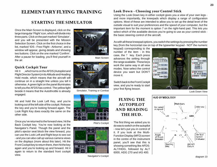
23
ELEMENTARY FLYING TRAINING
STARTING THE SIMULATOR
Once the Main Screen is displayed, click on thelarge triangular ‘Flight’ icon, which will divide intothree parts. Click on the part marked ‘Simulator’,and you will be presented with the MissionSelection Screen. Click on the first choice in thelist, marked ‘IDS - Free Flight - Airborne’, and awindow will appear, giving details and showingtwo buttons. Click on the one marked ‘Confirm’.After a pause for loading, you’ll find yourself inthe air.
Quick Cockpit TourHit 8, which turns on the AFDS (Autopilot andFlight Director System) in its Altitude and HeadingHold mode, which means that the aircraft willcontinue on in a straight line unless you tell itotherwise. A green light on the panel illuminatesto tell you the AFDS has control. The yellow lightbeside it means that the Autothrottle is alreadyengaged.
Hit and hold the Look Left Key, and you’relooking out of the left side of the cockpit. Releasethe key and you’re looking forward again. TheLook Right Key does exactly the same on theother side.
Once you’ve returned to the forward view, hit theBack Cockpit key. You’re now looking at theNavigator’s Panel. Though the panel and thepilot’s ejector seat block the view forward, youcan use the Look Left and Right keys to see out- and you can also call up various camera viewson the displays (more about this later). Hit theFront Cockpit key to return there, then hit the keyagain and you’re looking up and forward. Hit itagain to return to the standard front cockpitview.
Simulator, Training or Combat
Pilot's Cockpit
Navigator's Cockpit
Main Screen
Look Down - Choosing your Control StickUsing the Look Down key in either cockpit gives you a view of your own legs -and more importantly, the kneepads which display a range of configurationoptions. Most of these are intended to allow you to set up the detail level of theoutside visual to suit your preferences and the speed of your computer, but theimportant item for the moment is option 7 on the right-hand pad. This lets youselect which of the available devices you’re going to use as your control stick -the basic steering control of the aircraft.
As with all these kneepad options, you switch the settings by pressing the numberkey (from the horizontal row on top of the typewriter keypad - NOT the numerickeypad) corresponding to thenumber of the item - in thiscase, the 7 key. Each pressadvances the setting throughthe range available. These keyswork the same way in all viewmodes. Now select the controldevice you want but DON’Tmove it.
Switch back to the Front Cockpitview, and you’re ready to startyour first flying lesson.
FLYING THEAUTOPILOT
AND READINGTHE HUD.
The first thing we asked you todo was to switch on the autopilot- now let’s put you in control ofit. If you look at the Multi-Function Display (MFD) screenin the centre of the instrumentpanel, you’ll see that this isshowing something like AFDS:ALT/HDG, followed by ALT6000, HDG 270 and IAS 400.
Look Down View
diagram 10

24
These figures mean that the aircraft is trying to flyitself due West - a heading of 270°-at an altitudeof 6000 feet above sea level (flat ground level inthis case), and the Autothrottle has control of theengines and is trying to maintain an Indicated AirSpeed of 400 knots. This is the Altitude/HeadingAcquire and Hold mode of the AFDS. You tell itwhich way to fly and how high, and the aircraft willturn, climb or dive as necessary to fly in the rightdirection at the right height.
Look up at the Head Up Display (HUD) - diagram 10. At the top left you can seethe Indicated Air Speed figure - it should show 400 (knots). At the top right is theAltitude figure - this should read 6000 (feet). Across the bottom of the HUD is astrip of figures above a scale marked in dots, and under both is a short verticalline, which should be directly below the figure 27. This is the Heading Strip, andit’s telling you that the aircraft’s compass heading is 270°- all the figures on theheading strip represent TENS of degrees. These are the actual readings tellingyou how fast, how high and in which direction the aircraft is currently flying.
You should also take a look at the pairs of horizontal bars with turned-down innerends which appear in the wide central section of the HUD. These are called thePitch Bars (collectively the Pitch Ladder), and each is marked with an angle indegrees, at 10° intervals.
In this AFDS mode, your control stick does not fly the aircraft directly. Instead,you use it to alter the autopilot’s instructions, and the autopilot then flies theaircraft to carry them out. Let’s tell the aircraft to turn North. Move your controlstick slightly right while watching the HDG (Heading) line on the Multi-FunctionDisplay (MFD) screen. You should see the heading figure start increasingtowards 360° (at which point it snaps back to 0), and the aircraft will startmanoeuvering to follow. Set the Heading figure to somewhere between 0° and10°, moving the stick right or left to nudge the number up and down - but don’tworry about an exact value for the moment. If you’re using an analogue joystick,the further you push the stick, the faster the numbers change. If not, then thelonger you hold the stick over, or the key down, the faster the figures will change.If you hold the stick over too hard for too long and the AFDS heading figure goespast 090°, the aircraft will reverse its direction of turn because it’s now quickerto turn left than right to get there! Just set the heading figure somewhere near 0°and let the AFDS sort it out for itself.
If you look back up at the HUD and the outside world, you’ll see that the aircrafthas rolled - banked - to an angle of about 45°, and the figures on the heading stripare sliding across as the heading changes. You can also see that the bars of the
MFD in AFDS Mode
Pitch Ladder are at an angle on the HUD - they’ve stayed parallel with the horizonoutside - and they always do. Notice that the turned-down inner ends of the ladderbars point down at the ground - this, too, is always true.
When the aircraft rolls level again, youshould see that the reading on theHeading Strip is the same as theheading figure you set on the AFDSdisplay (diagram 11). Now look at theALT figure on the AFDS display. Pullingback on the stick will nudge this figureup, pushing forward will nudge it down.Set the figure to about 10000 feet. Theaircraft will raise its nose and startclimbing. On the HUD, you can see theAltitude figure changing, and the pointeron the ‘clock’ swinging clockwisearound it (diagram 12).
Half-way up on the right-hand side ofthe HUD is the VSI - the Vertical SpeedIndicator (diagram 13). This is shownas a vertical bar which rises or fallsfrom a centre position as the aircraftclimbs or dives. Its scale is calibratedwith dots at intervals of 5 feet persecond. If the rate of climb or descent isbigger than the scale allows (and itoften is), the bar extends to the end ofthe scale and stops. The precise rate ofclimb or descent is only normallyrelevant in the last stages of a landing,but the movements of the bar serve asa reminder of what the aircraft is doing.
If you look at the Pitch Ladder, you cansee that it’s showing that the aircraft’snose (represented by the circle-and-two-lines symbol in the centre of theHUD) is pointing above the horizon.Now hit the 8 key again, which willreset the Altitude Hold target to yourcurrent height. We’re about to reverseyour last action and command the
diagram 11
diagram 13
diagram 12

25
aircraft back down to its original height, but the aircraft will probably acceleratein the dive. With the wings swept forward for low-speed flight the aircraft willcomplain if asked to fly too fast. Hit the S key, pause for a second or two andthen hit S again. This will ensure that the wings are fully swept back for high-speed flight.
Now push the stick forward to set the AFDS desired altitude back to 6000 feet -no lower. You can see that the aircraft puts its nose down, the VSI changes fromshowing a climb rate to a rate of descent, and the pointer on the Altimeter ‘clock’is now swinging anticlockwise as the Altitude figure winds rapidly down. Lookingat the Pitch Ladder, you can see that whereas all the bars above the horizon aresolid, all the bars below the horizon are drawn as broken lines - another usefulreminder that your nose is pointed at the ground.
LEVEL TURNS AND AUTOTRIM
Remember the green and yellow lights near the top left of the panel? The greenlight is on when the autopilot has control, and the yellow light is on when theautothrottle is engaged.
When the aircraft is flying straight and level again, hit the q key. The green lightshould go out. Congratulations, you’ve just switched off the autopilot. If theaircraft was flying stably before you turned it off, nothing very much will changeunless you move the control stick.
During all of the following exercises feel free to use the P key to pause while youcatch up, read ahead or try to work out what’s going wrong. Hitting P again willrestart the simulation. If you end up in a situation you can’t handle, quit thesimulator by holding down c and Q simultaneously, then restart.
Move the control stick a short way to the left, and then release it to spring backto the centre. The aircraft should bank to the left and then stop rolling. If it doesn’tstop rolling, move the stick right andthen release. Try to set up a bank angleof about 45° and stop it there, but youdon’t have to be exact.
If you now look at the HUD and theoutside world, you should see that twothings are happening:
• The aircraft is turning slowly to the left.• The nose is dropping, and the aircraftis starting to dive and pick up speed.
Autopilot & Autothrottle EngageIndicators
Pull back gently on the stick, and hold it slightly back. This should produce tworesults:
• The rate of turn increases.• The nose should rise again. If it doesn’t, hold the stick back further.
When the nose is roughly level with the horizon, relax the back pressure on thestick and try to keep the nose on the horizon. The outside world and the Pitch Barson the HUD are the easiest visual references to use for this kind of manoeuvering.
If you’re trying to fly with the keyboard you won’t be able to use the stick this way.Because there is no way of reading how hard you’re pulling back, the stick forcejust increases as you hold the key down longer. There’s no way of reducing thestick force short of releasing the key altogether. All is not lost, however. Raise theaircraft’s nose until it’s level with the horizon or climbing slightly - the HUD VSIis a useful aid for this - and then quickly hit the Autotrim key (on most machinesthis will be the 5 key on the numeric keypad).
Autotrim is always available when the aircraft is upright, regardless of whetheror not you’re using the keypad as your control stick. When you engage Autotrim,you can move the control stick right or left to bank the aircraft to any angle shortof about 80°, and the Autotrim system will pull back as hard as necessary tomaintain the same rate of climb or descent. Autotrim is cancelled when you makeany pitch input (that is, when you pull back or push forward on the control stick),or when the bank angle approaches 90° and it just isn’t possible to keep the noseup any longer by simply pulling back on the stick.
At any time when the aircraft is not banked beyond 60°, you may re-engage theAFDS in Altitude and Heading Hold mode by hitting key 8, at which point it willtake the current heading and altitude as the values to hold. If you try to re-engagethe autopilot while the aircraft is rolled further than this limit all hell will appear tobreak loose as red lights start flashing and sirens sounding. It’s just the aircraft’sway of making sure that you know that the autopilot is NOT flying the aircraft foryou even though you tried to switch it on - you still have control. Cancel theWarning by hitting the * (numeric pad) or ' key and everything should returnto normal.
You can also see that the steeper the angle of bank, the harder you need to pullto maintain level flight, and the faster you turn (diagram 14). How hard can youpull? The Tornado’s wings are built to support 7.5 times the aircraft’s weight asa safe maximum, so at most you can make the Lift Vector seven and a half timeslonger than the Gravity Vector.

26
Positive G and G-LOCAs you may have realised, if you’re pulling this hard, you, the pilot, are beingpushed down into your seat with 7.5 times the force of gravity. If you keep this upfor too long, you will black out. Since thisusually means that you stop pulling, theforce becomes less, blood returns toyour brain, and you wake up again -unless you’ve crashed or been shotdown meanwhile. The situation issometimes known as G-LOC: G-inducedLoss Of Consciousness. The G-forcereading is shown on the G-meter (upperright centre) on the instrument panel.
G Meter
diagram 14
Negative GWhen you’re flying straight and level and you want to dive, the obvious way to dothis is to push the control stick forward to lower the nose. For small correctionsthis is a perfectly valid method, but pushing forward to enter a steep dive is nota good idea. The risk of red-out is one excellent reason to avoid this practice, theother is that it’s a slow way to manoeuvre - just not good enough in combat.
The reason it’s slow is because the aircraft’s negative-G limit is less than itspositive-G limit: -3 G against +7.5 G. Diagram 15 gives some idea of themaximum turn rates available by pulling +7.5 G as against pushing -3 G.
THEAUTOTHROTTLE
If you haven’t already doneso, hit 8 again for Headingand Altitude Hold, and watchthe HUD Airspeed figure untilit becomes steady. All thistime you’ve been flying withthe engines under control ofthe Autothrottle, which isthrottling the engines to tryand maintain the requestedIndicated Air Speed, which isshown on the AFDS display on the MFD. Just as the control stick (which flies theaircraft manually) is used to change the autopilot’s orders when the AFDS is flyingthe aircraft, so the throttle controls (which normally vary the engine RPMmanually) are used under Autothrottle to change the desired speed up and down.
The 0 key is used to switch Autothrottle on and off, and the yellow indicator lightnext to the green AFDS indicator turns on when the Autothrottle is engaged.When you switch from manual throttle to Autothrottle, it takes the currentIndicated Air Speed figure as its target speed. When you switch from Autothrottleto manual throttle control, the engine RPM and reheat settings stay at the lastvalue commanded by the Autothrottle.
Limits of the AutothrottleAutothrottle is an enormously useful feature, and you’ll probably want it switchedon most of the time you’re flying. For the moment, don’t set the Autothrottle targetspeed below about 250 knots - with the aircraft in its current configuration (i.e. withthe wings swept back as far as they will go), the aircraft will stop flying and stallnot far below this speed.
Other limitations exist mainly becausethe Autothrottle controls ONLY thethrottles. If it wants to accelerate theaircraft, all it can do is throttle up. If itwants to decelerate, all it can do isthrottle back. But if the aircraft is climbingat a steep angle, the engines simplycannot develop enough thrust to
diagram 15
Secondary Control SurfacesPosition Indicator

27
accelerate that much weight ‘uphill’, or even prevent the speed from dropping. Ifthe aircraft’s nose is pointed down in even a moderate dive, the aircraft willaccelerate as it coasts ‘downhill’ even though the Autothrottle has cut the enginesback to idle thrust (63% RPM).
You can cope with the first situation (the climb) either by climbing at a gentle anglewhich the engines can sustain (generally less than 20° nose-up) or by acceleratingto a high speed in level flight before pulling back into a steep climb (a ‘zoomclimb’). In this case you will lose speed in the climb, but you started with a highspeed, so you can carry on climbing for some time before the speed falls to adangerously low figure.
At ground level Indicated Air Speed is exactly the same as True Air Speed: speedthrough the air. As the aircraft climbs, however, the outside air pressure anddensity fall. The higher you go, the thinner the air. The amount of lift generatedby your wings depends largely on the speed and density of the air flowing over(and under) the wing. At higher altitudes and lower air densities you need to flyfaster just to stay in the air. The Indicated Air Speed figure takes air density intoaccount, and so for any given aircraft weight, wing sweep and flap setting theaircraft will always stall (i.e. stop flying) at the same IAS. If the pilot used a TASfigure the stall speed would increase with altitude, which would be confusing anddangerous.
At ground level an Indicated Air Speed of 200 knots means that your True AirSpeed is 200 knots. At 30000 feet, an IAS of 200 knots means that your TAS isabout 327 knots. In both cases you can look at the IAS figure and know that yourspeed is dangerously low - in fact, with wings fully swept back, the Tornado wouldquite possibly have stopped flying and started falling at 200 knots IAS.
Angle of AttackUse the AFDS in Altitude and Heading Hold mode to set the aircraft up in straightand level flight at an altitude of at least 8000 feet, with the autothrottle at about 400-
Airbrake on
Airbrake off
To handle the second situation (unwantedacceleration in a dive), use the Airbrakes. If youlook at the Airbrake Position Indicator (lower lefton the Panel) you’ll see a needle flick in and outas you deploy and close the Airbrakes. Thistechnique will work for moderate dive angles,but there is a limit to the effect.
Manoeuvre DragThere is another source of drag which can makeit impossible for the Autothrottle to maintain itstarget speed, and this is the drag caused bymanoeuvering. When you pull back hard on thestick you are forcing the wings to generate alarge amount of lift, but it is impossible to do thiswithout also generating a large amount of drag.If you set the aircraft up in level flight at aconstant speed under Autothrottle and then entera steep hard turn, you will see the Airspeed startto decay, while the Autothrottle cuts in maximumthrust and still can’t keep up.
STALLING
Indicated Air Speed - IASIndicated Air Speed (IAS) is one of four common ways of expressing an aircraft’sspeed. The others are True Air Speed (TAS), which represents the speed relativeto the air you’re flying through, Ground Speed, which is actual speed over theground, and Mach Number, which represents your speed as a multiple or afraction of the speed of sound at your current altitude.
450 knots. When you’ve donethis, turn the Autothrottle offby hitting 0, but leave theautopilot engaged. Use ‘Slamshut’ to bring the engines downto idle thrust - you should seethe RPM gauges drop to afigure of 63%.
Now watch the HUD AirspeedIndicator, the Pitch Ladder,and the vertical strip meter onthe left side of the HUD, opposite the VSI. This is the Angle-of-Attack (Alpha)meter (diagram 17). With the engines idling, the airspeed will drop, but you maywant to use the Airbrakes carefully to bring your speed down to about 250 knots- let your speed decay naturally from that point.You should see that as the speed drops, theautopilot maintains the set altitude. In order to doso it raises the nose more and more, which willshow up on the Pitch Ladder. At the same timethe Alpha meter shows a steadily rising trend.
diagram 17
diagram 16

28
Finally the stall point is reached, thenose drops uncontrollably. The AFDSsystem realises that it can’t handle thesituation and turns itself off - and tellsyou so by sounding an alarm andflashing the Attention-Getter lights. Nowit’s time for you to act: slam the throttleopen and push the control stick forward(you’re trying to accelerate to flyingspeed as fast as possible). As soon asyou see that the aircraft is actuallypitching down in response to yourcommand, pull the stick back GENTLYand level off. To cancel the Warning, hitthe * key on the numeric keypad or the' key.
WING SWEEP
• The further forward the wings areswept, the lower the stalling speed.
Engine r.p.m. Gauges
Secondary Control SurfacesPosition Indicator
45°sweep, zero flap
25° sweep, zero flap
• The further forward the wings are swept,the better the aircraft turns.• Whatever the sweep angle, the Alpha Meter isa more consistent indicator of an approachingstall than the Airspeed Indicator.
Mach NumberStarting with the aircraft flying level at about5000 feet with 25° sweep at about 400 knotsunder Autothrottle. Now set the Autothrottle forabout 480 knots and watch carefully as theaircraft accelerates. Before you’ve reached thetarget speed you’ll hear a rumbling, buffetingnoise and possibly notice some vibration. Whenyou do, sweep the wings back to the mid-sweepposition and the buffeting should stop.
You’ve just run into what are calledcompressibility effects - the fringes of what usedto be called the Sound Barrier. Though theaircraft as a whole is nowhere near the speed ofsound yet, the airflow over parts of the wings
was beginning to approach sonic speeds atdifferent places at different times. Shockwavesare constantly forming and collapsing in a chaoticpattern, causing turbulence and shaking theaircraft. If you had carried on accelerating withoutsweeping the wings back, the effect would havegrown more severe, and eventually the aircraftwould become uncontrollable and/or shake itselfto pieces. Sweeping the wings back delays theformation of the shockwaves until you reach ahigher speed.
67° sweep, zero flap
Now set the autothrottle for about 600 knots. Once again, as the aircraftaccelerates, you will hear and/or see buffeting, which will disappear if you sweepthe wings back all the way to 67°. You can now accelerate past the speed of sound(Mach 1) all the way to the limits of the aircraft’s performance at the currentaltitude before you will experience any further buffeting.
The critical Mach numbers (the numbers you shouldn’t normally exceed) are:
at 25° sweep: Mach 0.73
at 45° sweep: Mach 0.88
at 67° sweep: Mach 2.20
diagram 18
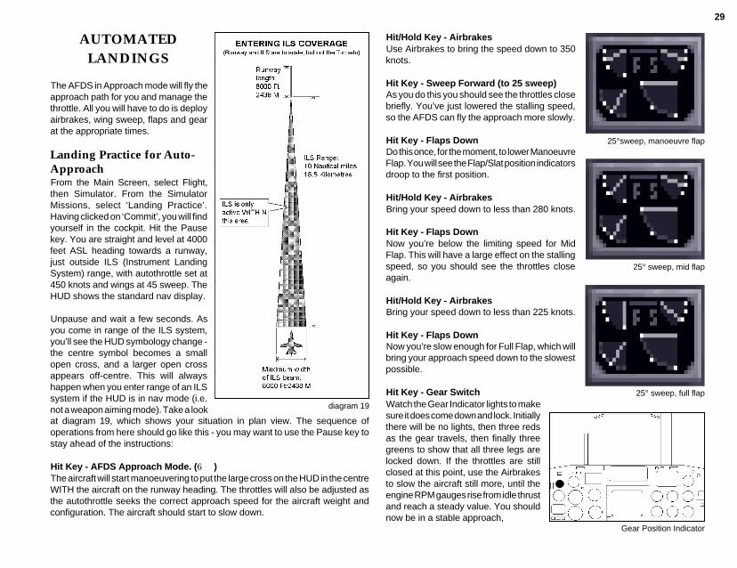
29
AUTOMATEDLANDINGS
The AFDS in Approach mode will fly theapproach path for you and manage thethrottle. All you will have to do is deployairbrakes, wing sweep, flaps and gearat the appropriate times.
Landing Practice for Auto-ApproachFrom the Main Screen, select Flight,then Simulator. From the SimulatorMissions, select ‘Landing Practice’.Having clicked on ‘Commit’, you will findyourself in the cockpit. Hit the Pausekey. You are straight and level at 4000feet ASL heading towards a runway,just outside ILS (Instrument LandingSystem) range, with autothrottle set at450 knots and wings at 45 sweep. TheHUD shows the standard nav display.
Unpause and wait a few seconds. Asyou come in range of the ILS system,you’ll see the HUD symbology change -the centre symbol becomes a smallopen cross, and a larger open crossappears off-centre. This will alwayshappen when you enter range of an ILSsystem if the HUD is in nav mode (i.e.not a weapon aiming mode). Take a lookat diagram 19, which shows your situation in plan view. The sequence ofoperations from here should go like this - you may want to use the Pause key tostay ahead of the instructions:
Hit Key - AFDS Approach Mode. (6)The aircraft will start manoeuvering to put the large cross on the HUD in the centreWITH the aircraft on the runway heading. The throttles will also be adjusted asthe autothrottle seeks the correct approach speed for the aircraft weight andconfiguration. The aircraft should start to slow down.
diagram 19
Hit/Hold Key - AirbrakesUse Airbrakes to bring the speed down to 350knots.
Hit Key - Sweep Forward (to 25 sweep)As you do this you should see the throttles closebriefly. You’ve just lowered the stalling speed,so the AFDS can fly the approach more slowly.
Hit Key - Flaps DownDo this once, for the moment, to lower ManoeuvreFlap. You will see the Flap/Slat position indicatorsdroop to the first position.
Hit/Hold Key - AirbrakesBring your speed down to less than 280 knots.
Hit Key - Flaps DownNow you’re below the limiting speed for MidFlap. This will have a large effect on the stallingspeed, so you should see the throttles closeagain.
Hit/Hold Key - AirbrakesBring your speed down to less than 225 knots.
Hit Key - Flaps DownNow you’re slow enough for Full Flap, which willbring your approach speed down to the slowestpossible.
Hit Key - Gear Switch
25°sweep, manoeuvre flap
25° sweep, mid flap
25° sweep, full flap
Gear Position Indicator
Watch the Gear Indicator lights to makesure it does come down and lock. Initiallythere will be no lights, then three redsas the gear travels, then finally threegreens to show that all three legs arelocked down. If the throttles are stillclosed at this point, use the Airbrakesto slow the aircraft still more, until theengine RPM gauges rise from idle thrustand reach a steady value. You shouldnow be in a stable approach,

30
descending smoothly toward therunway.
Now look for the Approach ProgressIndicator light (upper right on the panel),and wait for it to start flashing. When itdoes...
Hit Key - Cancel AutopilotThe aircraft should continue stably andsmoothly down the approach, hands-off, since everything is already set up.Watch the HUD Altimeter as youapproach the runway threshold, and asthe figure reaches 50 feet, start pullingback gently on the stick, until you cansee the rate of descent start to slowdown.
As the main gear touches down (youshould hear and see the thump, as wellas the 0 reading on the HUD altimeter),release the stick and...
Hit/Hold Key - Thrust ReversersThe Thrust Reverser buckets close overyour engine nozzles and divert thrustforward, slowing you down. Watch yourairspeed, and at about 70 knots..
Hit Key - Slam Throttle Shut
Release Key - Thrust Reversers
Hit Key - WheelbrakesYou must disengage the ThrustReversers before your speed dropsbelow about 50 knots, or your engineswill start re-ingesting their own exhaust,which will do them no good at all. Closethe throttle first, or you’ll just accelerateagain.
Secondary Control SurfacesPosition Indicator
Wheel Brakes
Thrust Reversers
Approach Progress Indicator
Operational ConditionsWhen you arrive at an Approach Point in Track Mode, the AFDS will automaticallyengage Approach Mode, and the aircraft will start to follow the ILS beam downto the runway. From this point on, the procedure is exactly the same as for theLanding Practice sequence.
TAKING OFF
From the Main Screen select Flight, and then the Simulator. On the MissionSelection Screen, choose the option ‘Free Flight (from runway)’. You will findyourself in the Mission Planner. If this isyour first take-off, just click on the buttonmarked ‘Take-off’, on the right-handside. You will find yourself in the cockpit,on the runway, with engines idling andMedium Flap selected, all ready to go.
Step 1. Fully open the throttle. You’llsee the Engine RPM gauges rise tillthey show 100%. At the same time, theFuel Flow gauge will show a moderaterise. Now release the Throttle control.Light up Reheat (Afterburners), by fullyopening the throttle again. The EngineRPM gauges will stay on 100%, butboth Reheat Indicators will light, and theFuel Flow gauge needle will spinclockwise and jam itself against thestop. The aircraft is now at absolutemaximum power, held only by the brakes- you may notice some vibration.
Step 2. Release the Wheelbrakes,watching the indicator to make sure itgoes out. The aircraft will start rolling.
Step 3. Watch the HUD AirspeedIndicator, and stand by with the ControlStick. When the speed reaches 140knots, pull the stick back and hold itback. If the aircraft is lightly loaded thenose will immediately start to rise, if it’sheavy this won’t happen until you have
Fuel Flow Indicator
Wheel Brake Indicator
Landing Gear Position Indicator
31
more speed. Hold the stick back until you’re pitched up about 8-12° according tothe HUD Pitch Bars, from just below to just above the first bar above the horizon.Now release the stick.
Step 4. Watch the HUD Altimeter. As soon as it leaves 0 you’re off the ground.You will also see the HUD VSI indicator rise to show that you’re climbing. Checkthe Airspeed to see that you’re still accelerating. If you are, hit the Landing GearSwitch to retract the undercarriage. Check the Gear Indicator, which shouldchange from three green lights (gear locked down) to three reds (not locked downor up), and finally go out altogether (locked up).
If you’re not accelerating, you’ve got the nose too high - push it down a little -carefully!
Step 5. Watch the HUD Airspeed Indicator. When you reach 215 knots, hit FlapsUp twice. You’ll see the Flap Position Indicator rise from Mid-Flap to ManouevreFlap to No Flap. You’re now cleaned up and ready to fly.
In short form, the drill goes like this:
Throttle OPEN, Reheat ON FULLWheelbrakes OFF (at 100% RPM and Max. Reheat)Pull back (at 140+ knots)Gear UP (at 10+ feet)Flaps UP (at 215 knots)
After Take-off, you will normally (in the Tornado IDS) be levelling off quite lowwhile you continue to accelerate to cruising speed - it should be quite safe toengage Track mode autopilot as you pass about 200'. Normal practice would beto cut Reheat as you pass 300 knots, and make the switch from 25 sweep to 45sweep at about 350 knots. Operationally, your next task will usually be to turn onthe AFDS in Track mode and watch the Time Early/Late indicator on the HUD,fine-tuning your speed with the autothrottle in order to arrive exactly on time atyour first en-route waypoint.
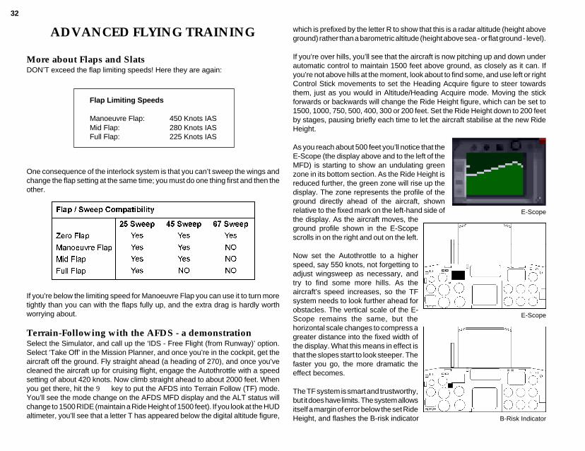
32
ADVANCED FLYING TRAINING
More about Flaps and SlatsDON’T exceed the flap limiting speeds! Here they are again:
One consequence of the interlock system is that you can’t sweep the wings andchange the flap setting at the same time; you must do one thing first and then theother.
If you’re below the limiting speed for Manoeuvre Flap you can use it to turn moretightly than you can with the flaps fully up, and the extra drag is hardly worthworrying about.
Terrain-Following with the AFDS - a demonstrationSelect the Simulator, and call up the ‘IDS - Free Flight (from Runway)’ option.Select ‘Take Off’ in the Mission Planner, and once you’re in the cockpit, get theaircraft off the ground. Fly straight ahead (a heading of 270), and once you’vecleaned the aircraft up for cruising flight, engage the Autothrottle with a speedsetting of about 420 knots. Now climb straight ahead to about 2000 feet. Whenyou get there, hit the 9 key to put the AFDS into Terrain Follow (TF) mode.You’ll see the mode change on the AFDS MFD display and the ALT status willchange to 1500 RIDE (maintain a Ride Height of 1500 feet). If you look at the HUDaltimeter, you’ll see that a letter T has appeared below the digital altitude figure,
which is prefixed by the letter R to show that this is a radar altitude (height aboveground) rather than a barometric altitude (height above sea - or flat ground - level).
If you’re over hills, you’ll see that the aircraft is now pitching up and down underautomatic control to maintain 1500 feet above ground, as closely as it can. Ifyou’re not above hills at the moment, look about to find some, and use left or rightControl Stick movements to set the Heading Acquire figure to steer towardsthem, just as you would in Altitude/Heading Acquire mode. Moving the stickforwards or backwards will change the Ride Height figure, which can be set to1500, 1000, 750, 500, 400, 300 or 200 feet. Set the Ride Height down to 200 feetby stages, pausing briefly each time to let the aircraft stabilise at the new RideHeight.
As you reach about 500 feet you’ll notice that theE-Scope (the display above and to the left of theMFD) is starting to show an undulating greenzone in its bottom section. As the Ride Height isreduced further, the green zone will rise up thedisplay. The zone represents the profile of theground directly ahead of the aircraft, shownrelative to the fixed mark on the left-hand side of
B-Risk Indicator
E-Scope
E-Scopethe display. As the aircraft moves, theground profile shown in the E-Scopescrolls in on the right and out on the left.
Now set the Autothrottle to a higherspeed, say 550 knots, not forgetting toadjust wingsweep as necessary, andtry to find some more hills. As theaircraft’s speed increases, so the TFsystem needs to look further ahead forobstacles. The vertical scale of the E-Scope remains the same, but thehorizontal scale changes to compress agreater distance into the fixed width ofthe display. What this means in effect isthat the slopes start to look steeper. Thefaster you go, the more dramatic theeffect becomes.
The TF system is smart and trustworthy,but it does have limits. The system allowsitself a margin of error below the set RideHeight, and flashes the B-risk indicator
Flap Limiting Speeds
Manoeuvre Flap: 450 Knots IASMid Flap: 280 Knots IASFull Flap: 225 Knots IAS

33
(a red light below the E-Scope) when it exceeds that margin. If the B-risk indicatoris flashing frequently, you should either slow down or increase the Ride Heightif the situation allows. There is also an absolute limit below the safety margin. Ifthe radar altitude falls this low, the system goes into panic reaction. It instantlyrolls the wings level and pulls up hard away from the ground, then automaticallydisengages itself and sounds a warning to tell you.
TEL (Time Early/Late) DisplaysOn the way to and from the target, Tornado IDS will normally fly in widely-spacedtactical formations, and it’s impossible to hold your place in the formation by eye.
When the mission flightplan is created, most of the waypoints are tagged withplanned times-of-arrival. When the aircraft is flying towards a selected waypointwhich has a set time-of-arrival, the navigation systems continuously calculate apredicted time-of-arrival on the basis of your current position and speed. Thedifference in seconds between the planned and predicted figures is shown as theTime Early/Late.
When the TEL HUD display is active, it appears as a short vertical line and threehorizontally-spaced dots just below the HUD Airpeed indicator. The vertical linemoves sideways between the centre positionand the outside dots, left for late and right forearly. If you’re right on time, the line is below thecentre dot; if it’s at the left dot you’re 30 secondslate or more; at the right dot you’re early by 30seconds or more. Smaller deflections left or rightindicate smaller deviations from the schedule.
While the TEL displays make really accurate timekeeping much easier, you'll findit difficult to achieve this in practice unless you have some idea of what speed themission plan required over each leg of the flight plan. This subject is treated inmuch more detail in the Mission Planner chapter, but in general you won't go farwrong if you assume that the flight plan expects a cruising speed of 420 knots,rising from 500-600 knots for attack and egress runs.
The drill for adjusting your speed to stay on schedule might go something like this:
1 Adjust Autothrottle setting for the nominal speed over the current leg of theflightplan.
2 Wait for the aircraft speed to adjust to the new setting and watch the TELindicator. If you’re late, adjust the speed upward, if early, reduce it. Rememberthat the adjustment won’t affect the TEL calculation until the actual aircraft speedhas changed.
When the aircraft reaches the currently selected waypoint while in AFDS Trackmode, the next waypoint in the flightplan is automatically selected and the aircraftturns towards it. If it’s a target, you’ll need to hit ‘arm air-to-ground weapons’. TheAFDS can fly most planned attacks for itself, though you’ll need to fly loft profilesmanually, and weapons cannot be released unless you hold down the Commitbutton. If the aircraft reaches an Approach Point within an allied ILS beam whileunder Track mode control, the AFDS will automatically switch to Approach modefor landing. If you want to fly parts of the flightplan manually, you’ll have toadvance the selected waypoint yourself at the end of each leg, using the SkipWaypoint command (see below).
When you reach a waypoint and the aircraft turns onto the next leg, the TELdisplays will not be active until the nose is pointing in the general direction of thenext waypoint.
Desperate Measures: Skipping WaypointsIt’s very simple to use; just move to the back seat, call up the PLN display if it’snot already visible, and hit the Skip Waypoint key (probably N) to advance thecurrently selected waypoint to the next in sequence. You can use this commandfrom the front seat if you wish, but it’s easier to see what’s going on if you watchthe PLN display.
You can repeat the comand as many times as you like, and cycle all the waythrough the list again if you overshoot, but if you leave the AFDS in Track modewhile you do it, be aware that the aircraft is going to twitch all over the place inresponse to the flurry of rapidly changing steering demands. Even moresignificantly, the altitude authority mode and height setting may change fromwaypoint to waypoint, possibly running you into a hill. To avoid this problem,disengage the AFDS and either fly the aircraft manually or re-engage in plain TFmode until you’ve selected the right waypoint.
SETTING UP YOUR OWN APPROACH ANDLANDING
Finding a runway, placing an Approach PointFinding a runway isn’t difficult if you use the map displays. The Full-screen map,zoomed well out, is probably the best one to start with. Use this to find an airfieldwhich is neither too close, nor too far away, and remember roughly which way itis from your current position (remember, the map rotates so that your aircraft isalways flying straight up the screen).
Now switch to the back cockpit and call up the Scrollable map on one of the Tabdisplays. Use a+left click to centre on your current position, zoom right out and
diagram 20

34
scroll the map in the right direction to find your target airfield. Refer back to theFull-screen map if necessary to find your way. When you bring the airfield on-screen you will be able to see that the active runway (the one you want to use)is shown in a contrasting colour.
diagram 21
diagram 22
With the airfield on screen andthe Scrollable Map zoomedright out, click the left mousebutton to place waypoint T about7 or 8 runway-lengths from theairfield, in line with the runway.You now have a home-madeapproach point. Hit T to makewaypoint T the currently-selected waypoint, and you canengage Track mode to fly youthere.
Why put theApproach Point there?As you can see from diagram22 the ILS beams cover a spike-shaped zone which is widestand highest at its furthest pointfrom the runway. This is about60000 feet (10 nautical miles or18 kilometres) from the runwaythreshold. Since all the activerunways you’ll find in Tornadoare about 8000 feet long, thismeans that the big end of thewedge is almost exactly 8runway-lengths from the middleof the runway. You’ll have to enter the ILS zone and point the aircraft in roughlythe right direction before the ILS displays will activate and AFDS Approach modecan be engaged.
You can see from diagram 23 that the beam is 8000 feet high at extreme range,and the AFDS will find it easiest to line up for the approach if you enter the beamnear the centre, so set the AFDS for Altitude hold (still under Track mode) at about4000 feet.
diagram 23
diagram 24A,B,C and D
How to line up for your ApproachDiagrams 24A,B and C illustrate a number of situations and possible ways ofdealing with them.

35
As you approach waypoint T,call up the Local Map on theMFD, select Base Origin display(aircraft at the bottom, not in themiddle) and look out for the letterT marking the position. Whenyou get close, cancel theAutothrottle and disengage theAFDS, then start your turn. Ifyou make it a tight turn you’lllose a good deal of speed aswell as staying closer to yourreference point.
Once you’re in the beam youcan engage the AFDS inApproach mode, but if you’recrossing the centreline at toogreat an angle and too high aspeed you’ll fly straight out ofthe other side of the beam beforethe AFDS can line up (seediagram 26). If this happens,the AFDS will turn itself off andsound a warning.
diagram 25
diagram 26
SEMI-AUTOMATIC AND MANUALLANDINGS
Semi-automatic Approach:- ILS and AutothrottleIn this type of approach we’ll use the ILS (Instrument Landing System) as amanual steering cue, and leave speed management to the Autothrottle. Youraircraft’s ILS displays are driven by transmitters and aerials on the ground,pointing up the approach path. There are effectively two fan-shaped radio beams;one (the Localiser) to tell you whether you are to the left or to the right of therunway centreline, and the other (the Glideslope) to tell you whether you areabove or below a steady 3° slope which meets the ground at the runwaythreshold. See diagram 22 for a full schematic.
The easiest form of the display to use is the one which automatically appears onthe HUD when you enter ILS coverage with the HUD in standard NAV mode (i.e.no weapon aiming displays). On the HUD ILS display, the aircraft datum in thecentre is shown as a cross and a second, larger cross moves left, right, up and
down to indicate which way it is to the centre ofthe ideal approach path. When you are in thecentre of the path the two crosses are exactlysuperimposed.
For comparison you can call up the MFD ILSdisplay by using the D key (MFD FunctionSelect) to cycle through the possible displays.Here the ILS display shows fixed dashedcrosshairs equivalent to the aircraft datum onthe HUD, and moving solid crosshairs whichcorrespond to the larger moving cross. Thisdisplay also shows, clockwise from top left;Aircraft Heading, Bearing to the airfield (to runwaymidpoint), Range to the airfield in nautical miles(to runway midpoint) and Time-to-go in minutesand seconds.
Reading and Reacting to the ILSdisplayOn the face of it, then, reaching the ideal approachpath is simply a question of flying the aircrafttowards the cross on the HUD. It’s not quite thatsimple - there are two other points to bear inmind. The first is that the ILS display is onlytelling you where you are relative to the idealapproach path - it is NOT telling you if you’repointed in the right direction to stay there. Tostay in the centre of the localiser beam (the left-right reference) you need to be pointing in thesame direction as the runway you’reapproaching. If you’re landing on runway 09 theaircraft’s got to be on a heading of 090° as wellas in the centre of the beam. Don’t make big,radical manoeuvres to try to reach the centre ofthe beam - the closer you get to it, the smalleryour corrections should be.
This is a highly important point, and one whichmany people find difficult to grasp: if the ILSdisplay is telling you that the runway centrelineis off to the left of your current position, it’s NOTtelling you to keep turning left until you reach it.If you’re approaching runway 09 and the ILS
diagram 27
MFD - ILS active
MFD - ILS (not active)
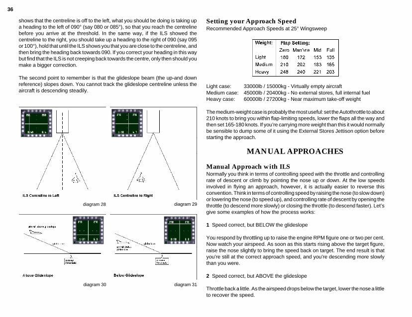
36
shows that the centreline is off to the left, what you should be doing is taking upa heading to the left of 090° (say 080 or 085°), so that you reach the centrelinebefore you arrive at the threshold. In the same way, if the ILS showed thecentreline to the right, you should take up a heading to the right of 090 (say 095or 100°), hold that until the ILS shows you that you are close to the centreline, andthen bring the heading back towards 090. If you correct your heading in this waybut find that the ILS is not creeping back towards the centre, only then should youmake a bigger correction.
The second point to remember is that the glideslope beam (the up-and downreference) slopes down. You cannot track the glideslope centreline unless theaircraft is descending steadily.
diagram 28 diagram 29
diagram 30 diagram 31
Setting your Approach SpeedRecommended Approach Speeds at 25° Wingsweep
Light case: 33000lb / 15000kg - Virtually empty aircraftMedium case: 45000lb / 20400kg - No external stores, full internal fuelHeavy case: 60000lb / 27200kg - Near maximum take-off weight
The medium-weight case is probably the most useful: set the Autothrottle to about210 knots to bring you within flap-limiting speeds, lower the flaps all the way andthen set 165-180 knots. If you’re carrying more weight than this it would normallybe sensible to dump some of it using the External Stores Jettison option beforestarting the approach.
MANUAL APPROACHES
Manual Approach with ILSNormally you think in terms of controlling speed with the throttle and controllingrate of descent or climb by pointing the nose up or down. At the low speedsinvolved in flying an approach, however, it is actually easier to reverse thisconvention. Think in terms of controlling speed by raising the nose (to slow down)or lowering the nose (to speed up), and controlling rate of descent by opening thethrottle (to descend more slowly) or closing the throttle (to descend faster). Let’sgive some examples of how the process works:
1 Speed correct, but BELOW the glideslope
You respond by throttling up to raise the engine RPM figure one or two per cent.Now watch your airspeed. As soon as this starts rising above the target figure,raise the nose slightly to bring the speed back on target. The end result is thatyou’re still at the correct approach speed, and you’re descending more slowlythan you were.
2 Speed correct, but ABOVE the glideslope
Throttle back a little. As the airspeed drops below the target, lower the nose a littleto recover the speed.
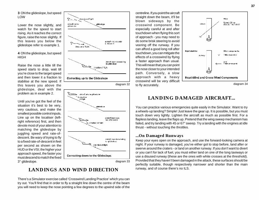
37
3 ON the glideslope, but speedLOW
Lower the nose slightly, andwatch for the speed to startrising. As it reaches the correctfigure, raise the nose slightly. Ifthis leaves you below theglideslope refer to example 1.
4 ON the glideslope, but speedHIGH
Raise the nose a little till thespeed starts to drop, wait tillyou’re close to the target speedand then lower it a fraction tostabilise at the new speed. Ifthis leaves you above theglideslope, deal with theproblem as in example 2.
Until you’ve got the feel of thesituation it’s best to be very,very cautious, and make thesmallest possible control inputs.Line up on the localiser (left-right reference) first, and thendevote most of your attention tomatching the glideslope byjuggling speed and rate-of-descent. Be wary of trying to flyto a fixed rate-of-descent in feetper second as shown on theHUD or the VSI; the higher yourapproach speed, the faster youmust descend to match the fixed3° glideslope.
diagram 32
diagram 33
LANDINGS AND WIND DIRECTION
There’s a Simulator exercise called ‘Crosswind Landing Practice’ which you cantry out. You’ll find that in order to fly a straight line down the centre of the beamyou will need to keep the nose pointing a few degrees to the upwind side of the
centreline. If you point the aircraftstraight down the beam, it’ll beblown sideways by thecrosswind component. Beespecially careful at and aftertouchdown when flying this sortof approach - you may need todo some brisk steering to avoidveering off the runway. If youcan afford a good long roll aftertouchdown, you can mitigate theeffects of a crosswind by flyinga faster approach than usual.This will mean that you can pointthe nose closer to your intendedpath. Conversely, a slowapproach with a heavycrosswind will be very difficultto fly accurately.
LANDING DAMAGED AIRCRAFT...
You can practice various emergencies quite easily in the Simulator. Want to trya wheels-up landing? Simple! Just leave the gear up. It is possible, but you musttouch down very lightly. Lighten the aircraft as much as possible first. For aflapless landing, leave the flaps up. Pretend that the wing sweep mechanism hasfailed, and try landing with 45 or 67° sweep. Try a landing with the engines at idlethrust - without touching the throttles.
...On Damaged RunwaysKeep your eyes open on the approach, and use the forward-looking camera atnight. If your runway is damaged, you’ve either got to stop before, land after orswerve around the craters - or land on another runway. If you don’t want to divertor you can’t for lack of fuel, you must either land on one of the long taxiways oruse a disused runway (these are the ones with white crosses at the threshold).Provided that they haven’t been damaged in the attack, these surfaces should beperfectly suitable, though respectively narrower and shorter than the mainrunway, and of course there’s no ILS.
diagram 34

38
EMERGENCIES
Jettison External Tanks onlyReleases the drop tanks on your inboard pylons to save weight and drag.
The green Jettison light illuminates to confirm separation.
Jettison Tanks and Offensive StoresThis is the option you need if hard-pressed by an enemy fighter in close combat,or in the event of engine damage. It dumps all external stores except AIM9L air-to-air missiles for self-defence.
The amber and green Jettison lights illuminate to confirm separation.
Jettison All External Stores and Internal Fuel down to 1000 lbs. /450 kg.This option is intended for use just before landing a damaged aircraft, if thesituation demands it. All external storesare dumped without exception, and allinternal fuel bar 1000 lbs with which tocomplete the approach, leaving you withan aircraft in its lightest possible poweredconfiguration.
The red, amber and green Jettison lightswill all illuminate to confirm that the storesare gone and the fuel dumped.
EjectionThere are two situations in which ejection is definitely the only way out. These arean engine fire, which (for our purposes) will always result in a catastrophicexplosion within a few seconds, or a loss of control with no prospect of recoverybefore the aircraft hits the ground. If and when an engine fire is detected thewarning system will go off and the condition will be flagged on the Warning Panelin the back cockpit. Loss of control can occur in many different ways, but you willprobably be in no doubt when it occurs.
SPILS, SPINS AND SPIN RECOVERY
SpinningSpinning is a hazard associated with stalling. When it is working, the SPILSsystem in the Tornado detects any incipient spin problem at the stall point andacts to correct it before the spin can become established. Like any other system
Jettison Lights
in the aircraft, however, the SPILS system may be disabled by combat damageor random failure. If this happens, any stall may develop into a spin - so you needto know how to recover once the spin has started.
Spin RecoveryThe Tornado’s spinning characteristics and recovery drill are unusual for tworeasons: first, it is a swing-wing aircraft and the nature of the spin changes withwing-sweep setting; second, it is unlike most other aircraft in that it has no aileroncontrol surfaces on the wings, moving the tail surfaces differentially instead.
Let’s set up the problem in the Simulator. Select one of the Free Flight (Airborne)exercises. When you arrive in the cockpit, turn off the SPILS system. This shouldprobably be done with the C+I key combination, but check with the ControlSummary for your machine (Secondary Flight Controls section). Be careful whendoing this: just hit the key once, because the control toggles SPILS on/off andthere’s no indicator apart from the one on the warning panel in the back, whichonly illuminates when the system fails due to damage, and NOT when you switchit off deliberately. Now sweep the wings right back to 67°, cancel Autothrottle andgo to full reheat (Slam Open twice). Let the aircraft accelerate to high speed onthe level, then cancel reheat (just Slam Shut while in reheat), leaving the throttlesat Max. Dry power (100% RPM). Pull the aircraft up into a near-vertical climb andtake your hands off the controls.
The aircraft will zoom-climb to ahigh altitude, losing speedrapidly. At about 220 knots IASyou should see the nose beginto drop in the stall. Now applyfull sideways stick - the directiondoesn’t matter. Suddenly theaircraft goes crazy - the HUDreferences and the instrumentsare all over the place and thehorizon flashes past your noseat short intervals and strangeangles. Hit 1 for an externalview and you’ll see that theaircraft is tumbling end over endin all three axes as it falls. Thisis characteristic spinningbehaviour when the wings arefully swept. diagram 35

39
Now hit the Sweep Forward key twice, to bring the wings to 25 sweep. As thewings move forward you should see the wild tumble stabilise into a rapid rotation.If you move back to the cockpit you will see that the horizon is now fairly stable,but the aircraft is twirling like a propeller. In order to recover from the spin you mustfirst identify which way the aircraft is rotating. This one excellent reason why youshould bring the wings to 25 sweep first, because it is extremely difficult to tellwhich way you’re going if the aircraft’s in a full-blooded tumble.
Having identified which way you’re turning: APPLY AND HOLD FULL BACKWARDSTICK AND PRO-SPIN AILERON! In other words, hold the stick right back andto the side you would normally use to bank in the direction you’re already turning.This is almost the exact opposite of the spin recovery drill used in most aircraft,which is classically performed by centering the stick, pushing it forward andapplying opposite rudder. This classical procedure is utterly useless in a spinningTornado.
Having applied full backward stick and pro-spin aileron, you will need to hold thestick in this position for a variable length of time, which will never be less than acouple of seconds and sometimes a good deal longer. Meanwhile watch theAltimeter and the Airspeed Indicator.
In a steady spin the Airspeed Indicator will show a very low figure, far belownormal flying speeds. One of the first signs that the recovery process is workingwill be a steady rise of speed. As the figure climbs towards the normal ranges youshould also see that the rotation rate is slowing. When it stops, the aircraft is undercontrol again, so immediately center the stick and (if you can still afford the heightloss) push the nose down to accelerate faster.
Here’s the Spin Recovery Procedure again, in short form:
Once you realise that the aircraft is spinning:
1 Eject immediately if there is insufficient height for a recovery (say 20000 feet),otherwise monitor altitude closely throughout the recovery process.
2 Command full forward sweep to 25°.
3 As soon as the direction of rotation is identified, apply and hold full backwardstick and pro-spin aileron.
4 First sign of recovery will be a sustained increase in airspeed.
5 When rotation ceases, accelerate to a safe speed as quickly as possible.
EXTERNAL VIEWS
(a) Tracking viewWhen first selected, you will be positioned immediately behind your aircraft,following at a fixed distance. If your prefer, you may use the zoom in and outfacility to adjust your perspective at either normal or fast rate.
When you’ve had enough of looking at tailpipes, try the “adjust tracking” controls.These allow you to swing your viewpoint around your aircraft in either direction,quickly or slowly, to give you a full 360° outside view. The “reset” option willposition you behind the aircraft again and for good measure we have the “togglelo/hi” feature which puts you level with your aircraft or slightly below it.
(b) Satellite viewSelect this option for a bird’s eye view looking directly down onto your aircraft.Select again and you’ll get a worm’s eye view looking up from underneath!
(c) Remote viewThis option allows you to hop outside and watch your aircraft from a fixed position.The viewpoint is fixed at the position of your aircraft at the moment of selection,and turns to follow your aircraft as you manoeuvre.
(d) Drone view“Drones” are the numerous computer-controlled aircraft and ground vehiclesmoving around the combat area simultaneously to yourself. By repeatedlypressing “drone view select” you may observe their activity and impress yourfriends. Zoom and track controls are available. You may also switch betweenallied and enemy drones, aircraft or ground vehicles.
(e) Weapon viewAgain, zoom and track adjust is available. Just prior to impact, air-to-groundweapons will switch to a plan view to help assess accuracy of delivery.
(f) Spectator viewWhen you select Spectator view, the viewpoint is ‘frozen’ in space wherever ithappens to be at that moment (unless it’s already a Spectator view), while theaction carries on.
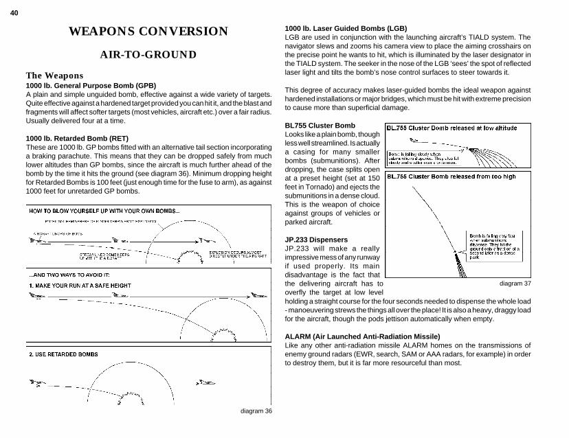
40
WEAPONS CONVERSION
AIR-TO-GROUND
The Weapons1000 lb. General Purpose Bomb (GPB)A plain and simple unguided bomb, effective against a wide variety of targets.Quite effective against a hardened target provided you can hit it, and the blast andfragments will affect softer targets (most vehicles, aircraft etc.) over a fair radius.Usually delivered four at a time.
1000 lb. Retarded Bomb (RET)These are 1000 lb. GP bombs fitted with an alternative tail section incorporatinga braking parachute. This means that they can be dropped safely from muchlower altitudes than GP bombs, since the aircraft is much further ahead of thebomb by the time it hits the ground (see diagram 36). Minimum dropping heightfor Retarded Bombs is 100 feet (just enough time for the fuse to arm), as against1000 feet for unretarded GP bombs.
diagram 36
1000 lb. Laser Guided Bombs (LGB)LGB are used in conjunction with the launching aircraft’s TIALD system. Thenavigator slews and zooms his camera view to place the aiming crosshairs onthe precise point he wants to hit, which is illuminated by the laser designator inthe TIALD system. The seeker in the nose of the LGB ‘sees’ the spot of reflectedlaser light and tilts the bomb’s nose control surfaces to steer towards it.
This degree of accuracy makes laser-guided bombs the ideal weapon againsthardened installations or major bridges, which must be hit with extreme precisionto cause more than superficial damage.
BL755 Cluster BombLooks like a plain bomb, thoughless well streamlined. Is actuallya casing for many smallerbombs (submunitions). Afterdropping, the case splits openat a preset height (set at 150feet in Tornado) and ejects thesubmunitions in a dense cloud.This is the weapon of choiceagainst groups of vehicles orparked aircraft.
JP.233 DispensersJP.233 will make a reallyimpressive mess of any runwayif used properly. Its maindisadvantage is the fact thatthe delivering aircraft has tooverfly the target at low level
diagram 37
holding a straight course for the four seconds needed to dispense the whole load- manoeuvering strews the things all over the place! It is also a heavy, draggy loadfor the aircraft, though the pods jettison automatically when empty.
ALARM (Air Launched Anti-Radiation Missile)Like any other anti-radiation missile ALARM homes on the transmissions ofenemy ground radars (EWR, search, SAM or AAA radars, for example) in orderto destroy them, but it is far more resourceful than most.
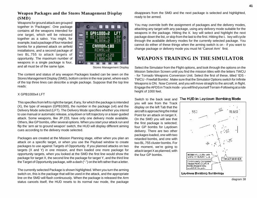
41
Weapon Packages and the Stores Management Display(SMD)Weapons for ground attack are groupedtogether in ‘Packages’. One packagecontains all the weapons intended forone target, which will be releasedtogether as a salvo. You might, forexample, load a package of four retardedbombs for a planned attack on airfieldinstallations, and a second package oftwo BL.755 to attack targets ofopportunity. The maximum number ofweapons in a single package is four,and all must be of the same type.
The content and status of any weapon Packages loaded can be seen on theStores Management Display (SMD), bottom centre in the rear panel, where eachof the top three lines can describe a single package. Suppose that the top linereads:
X GPB1000x4 LFT
This specifies from left to right the target, if any, for which the package is intended(X), the type of weapon (GPB1000), the number in the package (x4) and theDelivery Mode selected (LFT). The Delivery Mode specifies whether you intendto use manual or automatic release, a laydown or loft trajectory or a laser-guidedattack. Some weapons, like JP.233, have only one delivery mode available.Others, like GP bombs, offer several options. When you start your attack run andflip the ‘arm air to ground weapon’ switch, the HUD will display different aimingcues according to the delivery mode selected.
Packages are created at the Mission Planning stage, either when you plan anattack on a specific target, or when you use the Payload window to createpackages to use against Targets of Opportunity. If you planned attacks on twotargets (X and Y) in one mission, and then loaded one more package foropportunity targets, when you looked at the SMD the first line would show thepackage for target X, the second line the package for target Y, and the third linethe Target of Opportunity package, with a dash (“-”) on the left rather than a letter.
The currently selected Package is shown highlighted. When you turn the armingswitch on, this is the package that will be used in the attack, and the appropriateline on the SMD will flash continuously. When the package is released the Armstatus cancels itself, the HUD resets to its normal nav mode, the package
disappears from the SMD and the next package is selected and highlighted,ready to be armed.
You may override both the assignment of packages and the delivery modes,attacking any target with any package, using any delivery mode suitable for theweapons in the package. Hitting the K key will select and highlight the nextpackage down the list, or skip from the last to the first. Hitting the L key will cyclethrough the available delivery modes for the currently selected package. Youcannot do either of these things when the arming switch is on - if you want tochange package or delivery mode you must hit ‘Cancel Arm’ first.
WEAPONS TRAINING IN THE SIMULATOR
Select the Simulator from the Flight options, and look through the options on theMission Selection Screen until you find the mission titles with the letters TWCU- for Tornado Weapons Conversion Unit. Select the first of these, titled ‘IDS -TWCU - Freefall Bombs’. Make sure that the Simulator Options switch for InfiniteWeapons is ON. Now Commit, and you will move straight to the aircraft, in flight.Engage the AFDS in Track mode - you will find yourself Terrain-Following at a rideheight of 1000 feet.
Stores Management Display
Switch to the back seat andyou will see from the Trackdisplay on the left Tab that theaircraft is approaching the InitialPoint for an attack on target X.On the SMD you will see thatthe first package is selected;four GP bombs for Laydowndelivery. There are two otherpackages loaded, one with tworetarded bombs, and one withtwo BL.755 cluster bombs. Forthe moment, we’re going toattack target X as planned, withthe four GP bombs.
diagram 38
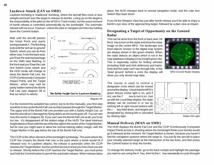
42
Laydown Attack (LAY on SMD)Laydown bombing is ‘traditional’ bombing, where the aircraft flies more or lessstraight and level over the target to release its bombs. Lining up on the target isthe responsibility of the pilot (or the AFDS in Track mode), but the exact momentof bomb release is controlled automatically by the bombsight. The automaticrelease will not occur, however, unless the pilot or navigator permits it by holdingdown the Commit button.
Wait until the aircraft passesthe Initial Point and startsturning towards X. The first thingto do is hit the ‘arm air-to-ground’Switch, which you can do fromeither seat. From the back seat,you’ll see the selected packageon the SMD start flashing. Inthe front seat you’ll see the LateArm Switch cover raised, andthe HUD mode will change toshow the Bomb Fall Line, theCCIP (Continuously ComputedImpact Point), and the TargetMarker, which may well bepartly hidden behind the BombFall Line (see diagram 38 tofind out which is which).
diagram 39
place, the HUD changes back to normal navigation mode, and the Late ArmSwitch flips back down.
If you hit the Weapon View key just after bomb release you’ll be able to enjoy abomb’s eye view of the approaching target, followed by a plan view at impact.
Designating a Target of Opportunity on the GroundRadar
MFD Ground Radar Display
This can be done from the front or back seat. Hitthe R key to turn on the radar and show the radarimage on the centre MFD. The landscape andfixed objects ‘known’ to the digital map systemare always shown in dim green shades. Whenthe radar detects an object which is not in themap database it displays it as a bright green dot.This is especially useful for finding vehicles(including SAM and AAA defences) and trains.Note that the radar can’t see through hills. In the‘dead ground’ behind a crest the display willshow you only stored map data.
The mouse is used to control adesignator cross which can be movedaround the display - check that the MFD’sgreen Mouse Active light is on, and ifnot, use the T key to turn it on. Justas with the Local Map display, the radardisplay can be zoomed in or out byclicking left or right mouse buttons withthe c key held down, and targets aredesignated by clicking left or cancelledby clicking right.
Manual Delivery (MAN on SMD)The HUD displays the Bomb Fall Line and the CCIP (Continuously ComputedImpact Point) across it, showing where the bombsight thinks your bombs wouldgo if released at this moment. No Target Marker is shown, because you haven’ttold the navigation systems where the target is. You just fly the aircraft to placeyour visually selected target at the intersection of the two lines, and then pressthe Commit button to drop the bombs.
To change the delivery mode; go to the back cockpit and highlight the packageyou want to use using the K key, then hit the L key repeatedly to cycle throught
Radar ON Light
For the moment the autopilot has control, but to do this manually, your first stepwould be to line up the Bomb Fall Line so that it passes through the Target Marker.The upper end of the Bomb Fall Line provides you with a Safety Height Cue, sothat the aircraft isn’t damaged by flying debris as the bomb goes off. You can seehow this works in diagram 39. If you can’t see the Bomb Fall Line at all, you’re fartoo low - it’s disappeared off the bottom edge of the HUD! The ideal minimumheight attack is flown with the top of the line right in the centre of the Target Marker,but for now you might want to allow the normal training safety margin, with theTarget Marker in the gap below the top of the Bomb Fall Line.
The CCIP is the other element of the bombsight symbology. The point where theCCIP line crosses the Bomb Fall Line is the point where a bomb would hit ifreleased now. In Laydown attacks, the release is automatic when the CCIPreaches the Target Marker, but the symbol serves to show you how close you areto release. Shortly before the CCIP reaches the Target Marker, you must pressand hold the Commit button to permit the automatic release. When release takes

43
the delivery mode options forthat package until you reachMAN. As with any weapondelivery mode, you must Armbefore you can drop thepackage.
Loft Delivery (LFT onSMD)A Loft attack also requires thatthe target position should beknown to the navigationsystems. A Loft attack comesin two phases: in the first yourun in at low level and fairlyhigh speed, starting a gooddistance (say 10 miles) fromthe target; you line up the BombFall Line with the Target Markerand wait for a ‘countdownclock’ on the HUD to countdown to zero. When thathappens, the second phasestarts as the HUD changes todisplay a ‘rubber triangle’steering cue and anothercountdown clock. You pull upinto a climb, trying to place thecross at the apex of the triangle(the Apex Marker) in the centreof the aircraft datum ring. Asyou do, the clock winds down.When it reaches zero thebombs are released (providedthat the Commit button is down)and you are free to get theaircraft out of the way. Thebombs fly on, rising to the topof a long arc and then curvingdown on or near the target.
diagram 40
diagram 41
target. The bombs would takeabout 20-25 seconds to reachthe target, climbing to 8-9000feet before they start todescend.
In a Loft attack, the bombstravel a very long way from therelease point with no form ofguidance, so absoluteaccuracy can’t be guaranteed.In practice, however, you’ll beamazed at how much accuracyis possible. Nonetheless, Loftbombing is not recommendedfor precision attacks. The greatadvantage of this form of attackis that the aircraft need notoverfly the target, and maynever even come within rangeof its defences.
Restart the Simulator ‘FreefallBombs’ mission, engage AFDSTrack mode and switch to theback cockpit. The first package,(four GP bombs) is alreadyselected and the delivery modeis shown as LAY. Hit the L keyto cycle round the deliveryoptions until the display showsLFT. When the aircraft turns torun in on target waypoint X, hitthe arming switch. The HUDwill now show the TargetMarker, a solid Bomb Fall Line,and a Countdown Clock slowlyunwinding anti-clockwisearound the Aircraft Datum. Use the Bomb Fall Line to line up on the Target Marker,or let the AFDS do it in Track Mode, and whether manually or under AFDS, setyour altitude to about 200 feet and your airspeed to about 550 knots. The Clockis counting down to the point where you start pulling up into a climb in order to loftthe bombs. This point, the Pull-up Point, is constantly recalculated on the basisof range to the target, speed (the faster you’re flying, the further you can throw
In a typical Loft attack, an aircraft running in at 550 knots at 200 feet would startits pull-up about five or six miles from the target and release its bombs just below1000 feet, climbing at an angle of just over 20° - still four or five miles from the
diagram 42
diagram 43

44
the bomb) and altitude (the higher you are,the further the bomb will fly). The Pull-upPoint is determined by the maximum range atwhich your lofted bombs could reach thetarget if released at your current height andspeed in a 45° climb. This is the climb angleat which you would achieve the theoreticalmaximum range.
As the Countdown Clock approaches zero,stand by. When the Pull-up Point is reached,the HUD symbology changes, to showanother Countdown Clock and a ‘RubberTriangle’ steering cue. The Clock shows thedifference between the range to the target,and the distance your bombs would be thrownif you released them now. The steering cuedirects you to pull up and steer left or right asnecessary to stay lined up with the target; thesmall cross (the Apex Marker) moves up anddown, left and right relative to the AircraftDatum, the base line of the triangle is fixedand the middle horizontal line is drawn halfwaybetween the two, skewing right or left as theApex Marker moves. The position of theApex Marker in relation to the Aircraft Datumtells you which way to steer - when you’repointed exactly the right way, the Apex Markeris in the exact centre of the ring of the AircraftDatum.
Assuming that you are still well lined up on thetarget, the Apex Marker will be directly abovethe centre of the Aircraft Datum, telling you topull straight up. If you’ve flown this far underAFDS control, now is the time to cancel it. Pullback firmly on the stick, and hold it back - thestandard practice is to pull up at about 3.5 G.As the aircraft pitches up and starts climbingyou will see the Countdown Clock run downrapidly as your bomb throw distanceincreases, and the Apex Marker will alsomove down closer to the ring centre. Both ofthese signs tell you that you’re getting closer diagram 44

45
to the release point. You may also see theApex Marker deflecting sideways. If it does,bank towards it to line up again, but don’tovershoot on the correction. When the Clockand the Apex Marker are indicating that you’renearly at release, hold down the Commit buttonand let the stick come forward to the neutralcentre position. At the moment of release, theHUD reverts to normal nav mode symbologyand the Arm status cancels, as for any otherdelivery mode. Diagram 44 shows a completesequence of HUD images for a loft attack.
Accuracy in a Loft AttackAs with any other form of attack you must lineup exactly on the target before release, butbecause the bombs travel so far in a loft attackany directional error will result in a miss by acorrespondingly large margin. If you can seeany heading error at all you must correct itbefore release or your bombs will be wasted.
The other great factor in loft accuracy is thepitch rate just before release. Remember thatthe bombs will be automatically released theinstant that the throw distance is equal to orgreater than the range to the target. Thebombsight computer repeats its calculationsfor bomb throw distance at very frequent
diagram 45A
diagram 45Bintervals, but each calculation takes time. If you are pulling up steeply, the throwdistances from successive calculations go up by leaps and bounds, and thethrow distance at release may overshoot the target by hundreds of feet. Diagram45A illustrates this problem, by showing how the predicted bomb trajectory andimpact point change at half-second intervals through a pull-up. You should beable to see that accuracy in these circumstances is a matter of blind luck. Ifinstead you let the stick come forward as the release point approaches diagram45B, the throw distance still increases as the aircraft climbs, but it increases inmuch smaller steps. The resulting release will stand a far better chance of beingaccurate in range.
Recovery and Escape after a Loft AttackThe moment the bombs are released you’re free to turn the aircraft away from thetarget and its defences, and you also want to avoid climbing so high that you’reexposed as an easy SAM or AAA target.
Delivering Laser-Guided Bombs (LGB on SMD)You can only laser-designate what the TIALD head under the aircraft can see,and the higher you are, the further you can see. We suggest an altitude of about23000 feet. As with Loft attacks, a long run-in is desirable (say 6 miles or more),but we want a moderate-to-low speed (say 250 knots IAS). An LGB attack isexecuted entirely from the navigator’s seat, with the aircraft under AFDS control.
Select and commit to the Simulator Mission ‘TWCU - LGB Attack’. This placesyou in flight at 23000 Feet, heading toward a Target Waypoint X on an airfield.Having assured yourself that the aircraft is heading in the right direction at theright speed under the AFDS, switch to the back seat. Looking at the StoresManagement Display you will see that you have one package of three LGBloaded, with the Delivery mode set to LGB. Use the ‘Right Tab Function Select’key to cycle through the right Tab display options till you see a downward-looking
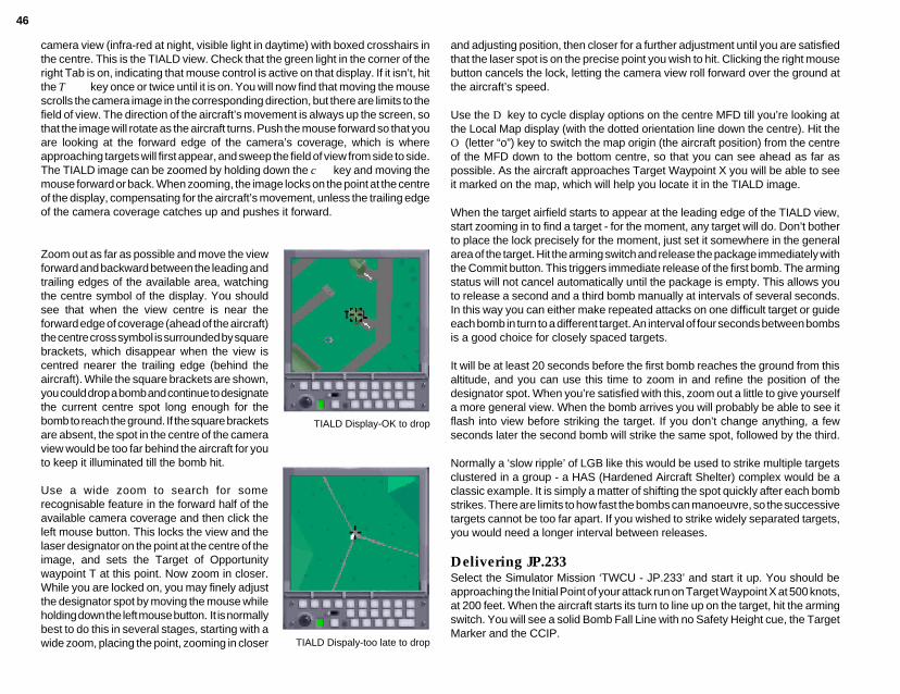
46
camera view (infra-red at night, visible light in daytime) with boxed crosshairs inthe centre. This is the TIALD view. Check that the green light in the corner of theright Tab is on, indicating that mouse control is active on that display. If it isn’t, hitthe T key once or twice until it is on. You will now find that moving the mousescrolls the camera image in the corresponding direction, but there are limits to thefield of view. The direction of the aircraft’s movement is always up the screen, sothat the image will rotate as the aircraft turns. Push the mouse forward so that youare looking at the forward edge of the camera’s coverage, which is whereapproaching targets will first appear, and sweep the field of view from side to side.The TIALD image can be zoomed by holding down the c key and moving themouse forward or back. When zooming, the image locks on the point at the centreof the display, compensating for the aircraft’s movement, unless the trailing edgeof the camera coverage catches up and pushes it forward.
Zoom out as far as possible and move the viewforward and backward between the leading andtrailing edges of the available area, watchingthe centre symbol of the display. You shouldsee that when the view centre is near theforward edge of coverage (ahead of the aircraft)the centre cross symbol is surrounded by squarebrackets, which disappear when the view iscentred nearer the trailing edge (behind theaircraft). While the square brackets are shown,you could drop a bomb and continue to designatethe current centre spot long enough for thebomb to reach the ground. If the square bracketsare absent, the spot in the centre of the cameraview would be too far behind the aircraft for youto keep it illuminated till the bomb hit.
Use a wide zoom to search for somerecognisable feature in the forward half of theavailable camera coverage and then click theleft mouse button. This locks the view and thelaser designator on the point at the centre of theimage, and sets the Target of Opportunitywaypoint T at this point. Now zoom in closer.While you are locked on, you may finely adjustthe designator spot by moving the mouse whileholding down the left mouse button. It is normallybest to do this in several stages, starting with awide zoom, placing the point, zooming in closer
TIALD Display-OK to drop
TIALD Dispaly-too late to drop
and adjusting position, then closer for a further adjustment until you are satisfiedthat the laser spot is on the precise point you wish to hit. Clicking the right mousebutton cancels the lock, letting the camera view roll forward over the ground atthe aircraft’s speed.
Use the D key to cycle display options on the centre MFD till you’re looking atthe Local Map display (with the dotted orientation line down the centre). Hit theO (letter “o”) key to switch the map origin (the aircraft position) from the centreof the MFD down to the bottom centre, so that you can see ahead as far aspossible. As the aircraft approaches Target Waypoint X you will be able to seeit marked on the map, which will help you locate it in the TIALD image.
When the target airfield starts to appear at the leading edge of the TIALD view,start zooming in to find a target - for the moment, any target will do. Don’t botherto place the lock precisely for the moment, just set it somewhere in the generalarea of the target. Hit the arming switch and release the package immediately withthe Commit button. This triggers immediate release of the first bomb. The armingstatus will not cancel automatically until the package is empty. This allows youto release a second and a third bomb manually at intervals of several seconds.In this way you can either make repeated attacks on one difficult target or guideeach bomb in turn to a different target. An interval of four seconds between bombsis a good choice for closely spaced targets.
It will be at least 20 seconds before the first bomb reaches the ground from thisaltitude, and you can use this time to zoom in and refine the position of thedesignator spot. When you’re satisfied with this, zoom out a little to give yourselfa more general view. When the bomb arrives you will probably be able to see itflash into view before striking the target. If you don’t change anything, a fewseconds later the second bomb will strike the same spot, followed by the third.
Normally a ‘slow ripple’ of LGB like this would be used to strike multiple targetsclustered in a group - a HAS (Hardened Aircraft Shelter) complex would be aclassic example. It is simply a matter of shifting the spot quickly after each bombstrikes. There are limits to how fast the bombs can manoeuvre, so the successivetargets cannot be too far apart. If you wished to strike widely separated targets,you would need a longer interval between releases.
Delivering JP.233Select the Simulator Mission ‘TWCU - JP.233’ and start it up. You should beapproaching the Initial Point of your attack run on Target Waypoint X at 500 knots,at 200 feet. When the aircraft starts its turn to line up on the target, hit the armingswitch. You will see a solid Bomb Fall Line with no Safety Height cue, the TargetMarker and the CCIP.
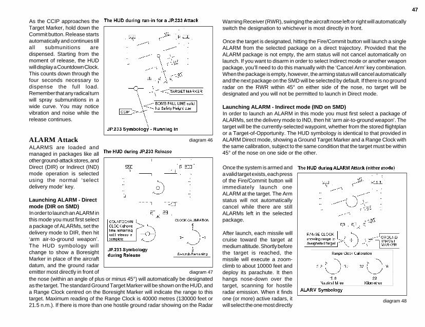
47
As the CCIP approaches theTarget Marker, hold down theCommit button. Release startsautomatically and continues tillall submunitions aredispensed. Starting from themoment of release, the HUDwill display a Countdown Clock.This counts down through thefour seconds necessary todispense the full load.Remember that any radical turnwill spray submunitions in awide curve. You may noticevibration and noise while therelease continues.
ALARM AttackALARMS are loaded andmanaged in packages like allother ground-attack stores, andDirect (DIR) or Indirect (IND)mode operation is selectedusing the normal ‘selectdelivery mode’ key.
Launching ALARM - Directmode (DIR on SMD)In order to launch an ALARM inthis mode you must first selecta package of ALARMs, set thedelivery mode to DIR, then hit‘arm air-to-ground weapon’.The HUD symbology willchange to show a BoresightMarker in place of the aircraftdatum, and the ground radaremitter most directly in front of
diagram 46
the nose (within an angle of plus or minus 45°) will automatically be designatedas the target. The standard Ground Target Marker will be shown on the HUD, anda Range Clock centred on the Boresight Marker will indicate the range to thistarget. Maximum reading of the Range Clock is 40000 metres (130000 feet or21.5 n.m.). If there is more than one hostile ground radar showing on the Radar
Warning Receiver (RWR), swinging the aircraft nose left or right will automaticallyswitch the designation to whichever is most directly in front.
Once the target is designated, hitting the Fire/Commit button will launch a singleALARM from the selected package on a direct trajectory. Provided that theALARM package is not empty, the arm status will not cancel automatically onlaunch. If you want to disarm in order to select Indirect mode or another weaponpackage, you’ll need to do this manually with the ‘Cancel Arm’ key combination.When the package is empty, however, the arming status will cancel automaticallyand the next package on the SMD will be selected by default. If there is no groundradar on the RWR within 45° on either side of the nose, no target will bedesignated and you will not be permitted to launch in Direct mode.
Launching ALARM - Indirect mode (IND on SMD)In order to launch an ALARM in this mode you must first select a package ofALARMs, set the delivery mode to IND, then hit ‘arm air-to-ground weapon’. Thetarget will be the currently-selected waypoint, whether from the stored flightplanor a Target-of-Opportunity. The HUD symbology is identical to that provided inALARM Direct mode, showing a Ground Target Marker and a Range Clock withthe same calibration, subject to the same condition that the target must be within45° of the nose on one side or the other.
diagram 48
Once the system is armed anda valid target exists, each pressof the Fire/Commit button willimmediately launch oneALARM at the target. The Armstatus will not automaticallycancel while there are stillALARMs left in the selectedpackage.
After launch, each missile willcruise toward the target atmedium altitude. Shortly beforethe target is reached, themissile will execute a zoom-climb to about 10000 feet anddeploy its parachute. It thenhangs nose-down over thetarget, scanning for hostileradar emission. When it findsone (or more) active radars, itwill select the one most directly
diagram 47
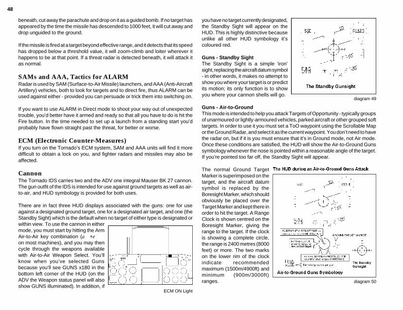
48
beneath, cut away the parachute and drop on it as a guided bomb. If no target hasappeared by the time the missile has descended to 1000 feet, it will cut away anddrop unguided to the ground.
If the missile is fired at a target beyond effective range, and it detects that its speedhas dropped below a threshold value, it will zoom-climb and loiter wherever ithappens to be at that point. If a threat radar is detected beneath, it will attack itas normal.
SAMs and AAA, Tactics for ALARMRadar is used by SAM (Surface-to-Air Missile) launchers, and AAA (Anti-AircraftArtillery) vehicles, both to look for targets and to direct fire, thus ALARM can beused against either - provided you can persuade or trick them into switching on.
If you want to use ALARM in Direct mode to shoot your way out of unexpectedtrouble, you’d better have it armed and ready so that all you have to do is hit theFire button. In the time needed to set up a launch from a standing start you’dprobably have flown straight past the threat, for better or worse.
ECM (Electronic Counter-Measures)If you turn on the Tornado’s ECM system, SAM and AAA units will find it moredifficult to obtain a lock on you, and fighter radars and missiles may also beaffected.
CannonThe Tornado IDS carries two and the ADV one integral Mauser BK 27 cannon.The gun outfit of the IDS is intended for use against ground targets as well as air-to-air, and HUD symbology is provided for both uses.
There are in fact three HUD displays associated with the guns: one for useagainst a designated ground target, one for a designated air target, and one (theStandby Sight) which is the default when no target of either type is designated orwithin view. To use the cannon in eithermode, you must start by hitting the ArmAir-to-Air key combination (a+eon most machines), and you may thencycle through the weapons availablewith Air-to-Air Weapon Select. You’llknow when you’ve selected Gunsbecause you’ll see GUNS x180 in thebottom left corner of the HUD (on theADV the Weapon status panel will alsoshow GUNS illuminated). In addition, if
ECM ON Light
you have no target currently designated,the Standby Sight will appear on theHUD. This is highly distinctive becauseunlike all other HUD symbology it’scoloured red.
Guns - Standby SightThe Standby Sight is a simple ‘iron’sight, replacing the aircraft datum symbol- in other words, it makes no attempt toshow you where your target is or predictits motion; its only function is to showyou where your cannon shells will go.
Guns - Air-to-GroundThis mode is intended to help you attack Targets of Opportunity - typically groupsof unarmoured or lightly-armoured vehicles, parked aircraft or other grouped softtargets. In order to use it you must set a ToO waypoint using the Scrollable Mapor the Ground Radar, and select it as the current waypoint. You don’t need to havethe radar on, but if it is you must ensure that it’s in Ground mode, not Air mode.Once these conditions are satisfied, the HUD will show the Air-to-Ground Gunssymbology whenever the nose is pointed within a reasonable angle of the target.If you’re pointed too far off, the Standby Sight will appear.
The normal Ground TargetMarker is superimposed on thetarget, and the aircraft datumsymbol is replaced by theBoresight Marker, which shouldobviously be placed over theTarget Marker and kept there inorder to hit the target. A RangeClock is shown centred on theBoresight Marker, giving therange to the target. If the clockis showing a complete circle,the range is 2400 metres (8000feet) or more. The two markson the lower rim of the clockindicate recommendedmaximum (1500m/4900ft) andminimum (900m/3000ft)ranges.
diagram 49
diagram 50
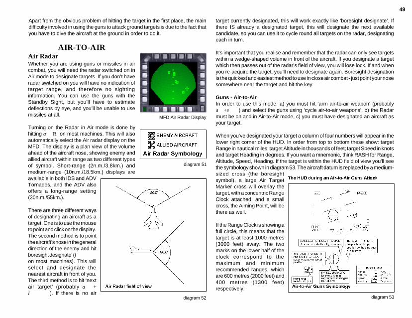
49
Apart from the obvious problem of hitting the target in the first place, the maindifficulty involved in using the guns to attack ground targets is due to the fact thatyou have to dive the aircraft at the ground in order to do it.
MFD Air Radar Display
AIR-TO-AIRAir RadarWhether you are using guns or missiles in aircombat, you will need the radar switched on inAir mode to designate targets. If you don’t haveradar switched on you will have no indication oftarget range, and therefore no sightinginformation. You can use the guns with theStandby Sight, but you’ll have to estimatedeflections by eye, and you’ll be unable to usemissiles at all.
Turning on the Radar in Air mode is done byhitting a R on most machines. This will alsoautomatically select the Air radar display on theMFD. The display is a plan view of the volumeahead of the aircraft nose, showing enemy andallied aircraft within range as two different typesof symbol. Short-range (2n.m./3.8km.) andmedium-range (10n.m./18.5km.) displays areavailable in both IDS and ADVTornados, and the ADV alsooffers a long-range setting(30n.m./55km.).
There are three different waysof designating an aircraft as atarget. One is to use the mouseto point and click on the display.The second method is to pointthe aircraft’s nose in the generaldirection of the enemy and hitboresight designate’ (lon most machines). This willselect and designate thenearest aircraft in front of you.The third method is to hit ‘nextair target’ (probably a +l). If there is no air
diagram 52
diagram 51
target currently designated, this will work exactly like ‘boresight designate’. Ifthere IS already a designated target, this will designate the next availablecandidate, so you can use it to cycle round all targets on the radar, designatingeach in turn.
It’s important that you realise and remember that the radar can only see targetswithin a wedge-shaped volume in front of the aircraft. If you designate a targetwhich then passes out of the radar’s field of view, you will lose lock. If and whenyou re-acquire the target, you’ll need to designate again. Boresight designationis the quickest and easiest method to use in close air combat - just point your nosesomewhere near the target and hit the key.
Guns - Air-to-AirIn order to use this mode: a) you must hit ‘arm air-to-air weapon’ (probablya+e) and select the guns using ‘cycle air-to-air weapons’, b) the Radarmust be on and in Air-to-Air mode, c) you must have designated an aircraft asyour target.
When you’ve designated your target a column of four numbers will appear in thelower right corner of the HUD. In order from top to bottom these show: targetRange in nautical miles; target Altitude in thousands of feet; target Speed in knotsand target Heading in degrees. If you want a mnemonic, think RASH for Range,Altitude, Speed, Heading. If the target is within the HUD field of view you’ll seethe symbology shown in diagram 53. The aircraft datum is replaced by a medium-sized cross (the boresightsymbol), a large Air TargetMarker cross will overlay thetarget, with a concentric RangeClock attached, and a smallcross, the Aiming Point, will bethere as well.
If the Range Clock is showing afull circle, this means that thetarget is at least 1000 metres(3000 feet) away. The twomarks on the lower half of theclock correspond to themaximum and minimumrecommended ranges, whichare 600 metres (2000 feet) and400 metres (1300 feet)respectively.
diagram 53
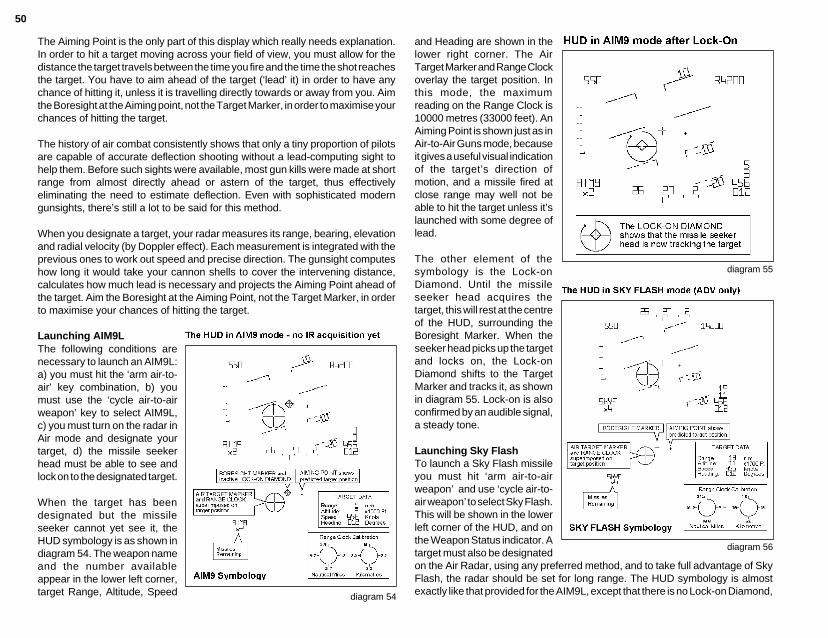
50
The Aiming Point is the only part of this display which really needs explanation.In order to hit a target moving across your field of view, you must allow for thedistance the target travels between the time you fire and the time the shot reachesthe target. You have to aim ahead of the target (‘lead’ it) in order to have anychance of hitting it, unless it is travelling directly towards or away from you. Aimthe Boresight at the Aiming point, not the Target Marker, in order to maximise yourchances of hitting the target.
The history of air combat consistently shows that only a tiny proportion of pilotsare capable of accurate deflection shooting without a lead-computing sight tohelp them. Before such sights were available, most gun kills were made at shortrange from almost directly ahead or astern of the target, thus effectivelyeliminating the need to estimate deflection. Even with sophisticated moderngunsights, there’s still a lot to be said for this method.
When you designate a target, your radar measures its range, bearing, elevationand radial velocity (by Doppler effect). Each measurement is integrated with theprevious ones to work out speed and precise direction. The gunsight computeshow long it would take your cannon shells to cover the intervening distance,calculates how much lead is necessary and projects the Aiming Point ahead ofthe target. Aim the Boresight at the Aiming Point, not the Target Marker, in orderto maximise your chances of hitting the target.
Launching AIM9LThe following conditions arenecessary to launch an AIM9L:a) you must hit the ‘arm air-to-air’ key combination, b) youmust use the ‘cycle air-to-airweapon’ key to select AIM9L,c) you must turn on the radar inAir mode and designate yourtarget, d) the missile seekerhead must be able to see andlock on to the designated target.
When the target has beendesignated but the missileseeker cannot yet see it, theHUD symbology is as shown indiagram 54. The weapon nameand the number availableappear in the lower left corner,target Range, Altitude, Speed diagram 54
and Heading are shown in thelower right corner. The AirTarget Marker and Range Clockoverlay the target position. Inthis mode, the maximumreading on the Range Clock is10000 metres (33000 feet). AnAiming Point is shown just as inAir-to-Air Guns mode, becauseit gives a useful visual indicationof the target’s direction ofmotion, and a missile fired atclose range may well not beable to hit the target unless it’slaunched with some degree oflead.
The other element of thesymbology is the Lock-onDiamond. Until the missileseeker head acquires thetarget, this will rest at the centreof the HUD, surrounding theBoresight Marker. When theseeker head picks up the targetand locks on, the Lock-onDiamond shifts to the TargetMarker and tracks it, as shownin diagram 55. Lock-on is alsoconfirmed by an audible signal,a steady tone.
Launching Sky FlashTo launch a Sky Flash missileyou must hit ‘arm air-to-airweapon’ and use ‘cycle air-to-air weapon’ to select Sky Flash.This will be shown in the lowerleft corner of the HUD, and onthe Weapon Status indicator. Atarget must also be designated
diagram 55
diagram 56
on the Air Radar, using any preferred method, and to take full advantage of SkyFlash, the radar should be set for long range. The HUD symbology is almostexactly like that provided for the AIM9L, except that there is no Lock-on Diamond,
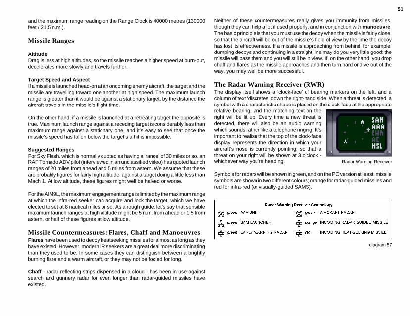
51
and the maximum range reading on the Range Clock is 40000 metres (130000feet / 21.5 n.m.).
Missile Ranges
AltitudeDrag is less at high altitudes, so the missile reaches a higher speed at burn-out,decelerates more slowly and travels further.
Target Speed and AspectIf a missile is launched head-on at an oncoming enemy aircraft, the target and themissile are travelling toward one another at high speed. The maximum launchrange is greater than it would be against a stationary target, by the distance theaircraft travels in the missile’s flight time.
On the other hand, if a missile is launched at a retreating target the opposite istrue. Maximum launch range against a receding target is considerably less thanmaximum range against a stationary one, and it’s easy to see that once themissile’s speed has fallen below the target’s a hit is impossible.
Suggested RangesFor Sky Flash, which is normally quoted as having a ‘range’ of 30 miles or so, anRAF Tornado ADV pilot (interviewed in an unclassified video) has quoted launchranges of 20 miles from ahead and 5 miles from astern. We assume that theseare probably figures for fairly high altitude, against a target doing a little less thanMach 1. At low altitude, these figures might well be halved or worse.
For the AIM9L, the maximum engagement range is limited by the maximum rangeat which the infra-red seeker can acquire and lock the target, which we haveelected to set at 8 nautical miles or so. As a rough guide, let’s say that sensiblemaximum launch ranges at high altitude might be 5 n.m. from ahead or 1.5 fromastern, or half of these figures at low altitude.
Missile Countermeasures: Flares, Chaff and ManoeuvresFlares have been used to decoy heatseeking missiles for almost as long as theyhave existed. However, modern IR seekers are a great deal more discriminatingthan they used to be. In some cases they can distinguish between a brightlyburning flare and a warm aircraft, or they may not be fooled for long.
Chaff - radar-reflecting strips dispensed in a cloud - has been in use againstsearch and gunnery radar for even longer than radar-guided missiles haveexisted.
Neither of these countermeasures really gives you immunity from missiles,though they can help a lot if used properly, and in conjunction with manoeuvre.The basic principle is that you must use the decoy when the missile is fairly close,so that the aircraft will be out of the missile’s field of view by the time the decoyhas lost its effectiveness. If a missile is approaching from behind, for example,dumping decoys and continuing in a straight line may do you very little good: themissile will pass them and you will still be in view. If, on the other hand, you dropchaff and flares as the missile approaches and then turn hard or dive out of theway, you may well be more successful.
The Radar Warning Receiver (RWR)The display itself shows a ‘clock-face’ of bearing markers on the left, and acolumn of text ‘discretes’ down the right-hand side. When a threat is detected, asymbol with a characteristic shape is placed on the clock-face at the appropriaterelative bearing, and the matching text on theright will be lit up. Every time a new threat isdetected, there will also be an audio warningwhich sounds rather like a telephone ringing. It’simportant to realise that the top of the clock-facedisplay represents the direction in which youraircraft’s nose is currently pointing, so that athreat on your right will be shown at 3 o’clock -whichever way you’re heading.
Symbols for radars will be shown in green, and on the PC version at least, missilesymbols are shown in two different colours; orange for radar-guided missiles andred for infra-red (or visually-guided SAMS).
Radar Warning Receiver
diagram 57

52
AIRCREW NOTES
COCKPIT LAYOUT
Instruments Key
1 Reverse thrust indicators
2 Attention getter
3 Autopilot engaged indicator
4 Autothrottle engaged indicator
5 Wheel brakes
6 Landing gear position indicator
7 Radar altimeter
8 “B” risk indicator
9 Vertical speed indicator (VSI)
10 Indicated airspeed / Mach number
11 Secondary control surfaces position indicator
12 Altimeter
13 Jettison all external stores + internal fuel
14 Jettison all external stores except AIM9-L
15 Jettison external fuel tanks
16 Angle of attack indicator
17 E-Scope (IDS) or weapon status (ADV)
18 Horizontal situation indicator (HSI)
19 Attitude direction indicator (ADI)
20 Head up display (HUD)
21 Late arm switch
22 Head up display control panel
23 Multi-function display (MFD)
24 Mouse active indicator
25 Radar “on” indicator
26 ECM “on” indicator
27 Radar warning receiver
28 Engine r.p.m. indicators (left & right)
29 Engine temperature indicators (left & right)
30 Approach progress indicator
31 Reheat operating lights
32 G meter
33 Fuel flow indicator
34 Fuel quantity indicator
35 Standby compass
36 Oxygen flow indicator
Pilot's Instrument Panel
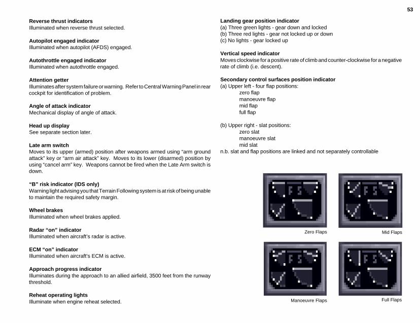
53
Reverse thrust indicatorsIlluminated when reverse thrust selected.
Autopilot engaged indicatorIlluminated when autopilot (AFDS) engaged.
Autothrottle engaged indicatorIlluminated when autothrottle engaged.
Attention getterIlluminates after system failure or warning. Refer to Central Warning Panel in rearcockpit for identification of problem.
Angle of attack indicatorMechanical display of angle of attack.
Head up displaySee separate section later.
Late arm switchMoves to its upper (armed) position after weapons armed using “arm groundattack” key or “arm air attack” key. Moves to its lower (disarmed) position byusing “cancel arm” key. Weapons cannot be fired when the Late Arm switch isdown.
“B” risk indicator (IDS only)Warning light advising you that Terrain Following system is at risk of being unableto maintain the required safety margin.
Wheel brakesIlluminated when wheel brakes applied.
Radar “on” indicatorIlluminated when aircraft’s radar is active.
ECM “on” indicatorIlluminated when aircraft’s ECM is active.
Approach progress indicatorIlluminates during the approach to an allied airfield, 3500 feet from the runwaythreshold.
Reheat operating lightsIlluminate when engine reheat selected.
Landing gear position indicator(a) Three green lights - gear down and locked(b) Three red lights - gear not locked up or down(c) No lights - gear locked up
Vertical speed indicatorMoves clockwise for a positive rate of climb and counter-clockwise for a negativerate of climb (i.e. descent).
Secondary control surfaces position indicator(a) Upper left - four flap positions:
zero flapmanoeuvre flapmid flapfull flap
(b) Upper right - slat positions:zero slatmanoeuvre slatmid slat
n.b. slat and flap positions are linked and not separately controllable
Zero Flaps Mid Flaps
Full FlapsManoeuvre Flaps

54
Airbrake offAirbrake on
(c) Lower left - airbrake position
(d) Lower right - wing sweep:
25° sweep 45°sweep
67° sweep
Jettison indicatorsThree lights to confirm successful jettison of:Left: all external stores plus internal fuel to
minimumCentre: all external stores except AIM9-LRight: external fuel tanks
Radar altimeterIndicates height above ground level when below5000 feet barometric. Non-linear scale withhighest resolution at low altitude.
Indicated Airspeed / Mach numberAnalogue dial showing Indicated Airspeed up to800 knots and digital readout of Mach number.
IAS/Mach number
AltimeterAnalogue dial showing barometric altitude.
E-scope (IDS) or Weapon status (ADV)(a) E-scope (IDS Tornado)Shows projection of terrain ahead of aircraft when flyingat low altitudes.(b) Weapon status (ADV Tornado)The weapons status indicator shows which air-to-airweapon is selected (highlighted) and armed (flashing).The pilot may select between guns, AIM9-L Sidewinderor Sky Flash. The weapon name will not highlight if it isnot available.
Altimeter
E-scope on IDSWeapon Status on ADV
Attitude direction indicatorOtherwise known as an artificial horizon, this instrument shows the pitch and rollattitude of your aircraft relative to the ground. For example, pitch up and theartificial horizon will fall, roll right and the artificial horizon rolls left. A small “bug”travels around the circumference of this instrument showing your roll orientation.This is particularly useful when your aircraft is pitched so far up or down that thehorizon is no longer visible.
Level Flight Rolled 90° right Flying Inverted Rolled 90° left

55
Horizontal situation indicator (HSI)This instrument has two functions:Firstly, it indicates your aircraft’s heading by meansof a “bug” travelling around the circumference ofthe compass rose.
examples:bug at 12 o’clock heading due Northbug at 3 o’clock heading due Eastbug at 6 o’clock heading due Southbug at 9 o’clock heading due West
Secondly, it is part of the Instrument Landing System and shows localiser andglideslope deviation during an approach to an allied airfield.
The vertical needle is linked to the runway localiser and shows deviation from therunway centreline. A small vertical scale can be seen on the left of the instrumentand this may be used to follow the correct glideslope down to the runwaythreshold.
Below GlideslopeRunway to your left
Mouse active indicatorWhen mouse control is appropriate to more than one current display e.g. with theradar on the MFD and the moving map on a TV TAB display, control may bepassed between the displays by use of the “Select active display” key. Theindicator will illuminate to confirm mouse control is active.
Engine rpm indicatorsIndividual analogue rpm indicator for eachengine (left and right). Normally shows 63% atengine idle. Full scale deflection of 100% atmaximum dry thrust (no reheat) and throughoutall reheat settings.
Engine r.p.m. Indicators
Engine temperature indicatorsIndividual analogue temperature indicator foreach engine (left and right). Normal reading of400°C at idle and 700°C at full reheat. Higherthan this probably means that you are on fire.....
Engine Temperature IndicatorsG meterShows g force due to aircraft manoeuvres. For straightand level flight the reading will be 1g with the pointer at the9 o’clock position. Maximum positive g force of 7.5,maximum negative g force of -3.
Fuel flow indicatorVery little movement is evident on this instrument unlessreheat is selected. This instrument is then particularlyuseful for assessing the extent of reheat in use.
Fuel quantity indicatorShows total quantity of fuel remaining. Fuel in externaltanks is represented by the red-bordered sector from 12to 3 o’clock on the gauge.
Standby compassShows magnetic compass heading of aircraft.
Radar warning receiverThis display shows when your aircraft is being tracked byenemy radar, both ground-based (e.g. SAM or AAA) andairborne (e.g. fighter aircraft). The display also showsincoming ground-launched or air-launched missiles, bothinfra-red and radar-guided. Discretes on the right of thedisplay will illuminate as follows:
G Meter
Fuel Flow Indicator
Fuel Quantity Indicator
Radar Warning Receiver
SAM you are being tracked by a SAMlauncher
AAA you are being tracked by anti-aircraftartillery
EWR you are being tracked by ground-basedearly warning radar
AC you are being tracked by an enemyaircraft
MSL incoming missile, infra-red or radar-guided, ground or air-launched
Bug at 12 o'clockflying north

56
Bomb fall lineLine along which the bomb willfall after release.
Countdown clockCounts down to the “pull uppoint” and the start ofstage 2.
Ground target markerPosition of designated targetas seen through the HUD.
ILS steering markerThe steering marker is linkedto the runway localiser andglideslope ILS transmitters.If you are aligned with therunway centreline andfollowing the requiredglideslope, the steeringmarker will overlay the aircraftdatum symbol in the centre ofthe HUD. If the marker is offcentre, steer towards it.
Bomb fall lineLine along which the bombwill fall after release. Safetyheight cue gives indication ofsafety margin so that pilot mayavoid flying through debrishemisphere of explodingweapon.
Continuously computedimpact point (CCIP)Marker across the bomb fallline showing the bomb’scomputed impact point ifreleased immediately.
Ground target markerPosition of designated targetas seen through the HUD.
Countdown clockShows the difference betweenthe range to the target and thedistance your bombs would bethrown if you released themimmediately. Unwinds as youraircraft approaches weaponrelease. Calibration dependentupon weapon type.
Rubber triangleA steering cue consisting of anapex point (small +), a shortmiddle line and a long baseline. The position of the baseline is fixed. The apex markermoves left,right,up and downrelative to the aircraft datum toindicate a steering demand tothe pilot. The middle line isdrawn half way between theapex marker and the base lineand moves left and right.

57
Bomb fall lineLine along which the bomb willfall after release.
Continuously computedimpact point (CCIP)Marker across the bomb fallline showing the bomb’scomputed impact point ifreleased immediately.
Ground target markerPosition of designated targetas seen through the HUD.
Countdown clockAppears when the CCIPreaches the target marker.Counts down through the fourseconds necessary todispense the full weapon load.
Bomb fall lineLine along which the bomb willfall after release. Safety heightcue gives indication of safetymargin so that pilot may avoidflying through debrishemisphere of explodingweapon.
Continuously computedimpact point (CCIP)Marker across the bomb fallline showing the bomb’scomputed impact point ifreleased immediately.
BoresightThis replaces the aircraftdatum.
Range clockDisplays range to target withmaximum range of 21.5 nm(40 km)
Ground target markerPosition of designated targetas seen through the HUD.
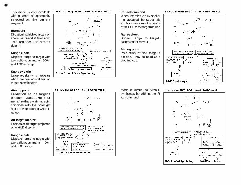
58
This mode is only availablewith a target of opportunityselected as the currentwaypoint.
BoresightDirection in which your cannonshells will travel if fired now.This replaces the aircraftdatum.
Range clockDisplays range to target withtwo calibration marks: 900mand 1500m range
Standby sightLarger red sight which appearswhen cannon armed but notarget is designated.
Aiming pointPrediction of the target’sposition. Manoeuvre youraircraft so that the aiming pointcoincides with the boresightand fire your cannon when inrange.
Air target markerPosition of air target projectedonto HUD display.
Range clockDisplays range to target withtwo calibration marks: 400mand 600m range
IR Lock diamondWhen the missile’s IR seekerhas acquired the target thissymbol moves from the centreof the HUD to the target marker.
Range clockShows range to target,calibrated for AIM9-L.
Aiming pointPrediction of the target’sposition. May be used as asteering cue.
Mode is similar to AIM9-Lsymbology but without the IRlock diamond.

59
Navigator/Weapons Officer’s seat
Instruments Key
Items common with front cockpit1 Mouse active indicator2 Landing gear position indicator3 Attitude direction indicator4 Horizontal situation indicator5 Altimeter6 Indicated airspeed / Mach number7 Multi function display8 Mouse active indicator9 Autopilot engaged indicator10 Autothrottle engaged indicator11 Radar “on” indicator12 ECM “on” indicator13 Mouse active indicator
Items unique to rear cockpit14 Left TV TAB display15 Analogue clock16 Stores management display17 Right TV TAB display18 Central warning panel
Navigator's Instrument Panel
Stores Management DisplayThis small screen is dedicated to the display ofavailable weapon packages and the selection ofweapon delivery modes. All available weaponswill be listed together with chaff and flareavailability. If necessary, prior to arming, use the“Select weapon package” key to highlight therequired weapon during your approach to thetarget and use the “Select delivery mode” key tospecify your method of attack. The highlightedname will flash once you have armed the weapon.
Central Warning PanelThe large panel to the right of theStores Management Display is usedto determine the nature of systemfailures and warnings. Refer to thispanel when the front cockpit attentiongetters are flashing. You may cancelthe attention getters by pressing“master warning reset” key.
Central Warning Panel
Stores Management Display
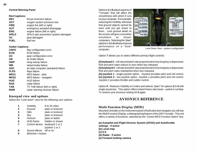
60
Options 1 to 6 adjust aspects of“Tornado” that will affect thesmoothness with which it runson your computer. For example,reducing the Visibility will meanthat ground objects cannot beseen until you get closer tothem. Less ground detail onthe screen will give a smoothersimulation on slowercomputers. Selecting the “plain”options in 2 to 5 will also improveperformance on a “slow”computer.
Option 7 allows you to select different primary flight controls:
(i) keyboard 1 - roll rate and pitch rate proportional to how long key is depressed.Roll and pitch rates reduce to zero when key released.(ii) keyboard 2 - roll rate and pitch rate proportional to how long key is depressed.Roll and pitch rates maintained when key released.(iii) joystick 1 - single joystick option. Joystick provides pitch and roll control.(iv) joystick 2 - two joystick option. Joystick 1 provides pitch and roll control.Joystick 2 provides throttle and rudder control.
Option 0 - Reduces Visibility to 6 miles and selects “plain” for options 2 to 5 withsingle keystroke. This option offers instant frame rate boost - useful in combat.To restore your previous setting hit 0 again.
AVIONICS REFERENCE
Multi Function Display (MFD)Mounted centrally on the instrument panel of both pilot and navigator you will seethe Multi Function Display, a distinguishing feature of the GR4 Tornado. This unitoffers a variety of functions, selected by the “Centre MFD Function Select” key:
(a) Autopilot and Flight Director System (AFDS) and Autothrottlesettings - if active(b) Local map(c) ILS(d) Radar - if active(e) Forward looking camera
Central Warning Panel
Red Captions:REV thrust reversers failureOXY oxygen system pressure lowFIRE engine fire (left or right)AUT emergency autopilot disengageENG engine failure (left or right)SPILS SPILS spin prevention system damagedUC gear damagedFUEL fuel low
Amber Captions:CNFG flap configuration errorECM ECM failureUC gear configuration errorAB air brake failureSWP wing sweep failureWB wheel brake failureADC air data computer (autopilot) failureFLPS flaps failureMFD1 MFD failure - pilotMFD2 MFD failure - navigatorHUD HUD failureRAD radar failureTAB TV TAB failure (left or right)RWR radar warning receiver failure
Kneepad view and optionsSelect the “Look down” view for the following user options:
1 Visibility 6 to 25 miles2 Ground plain or textured3 Hills plain or textured4 Sky plain or textured5 Horizon plain or faded6 HUD frame hidden or shown7 Control device keyboard 1 or 2
joystick 1 or 28 Sound effects off or on0 Minimise / restore
Look Down View - system configuration
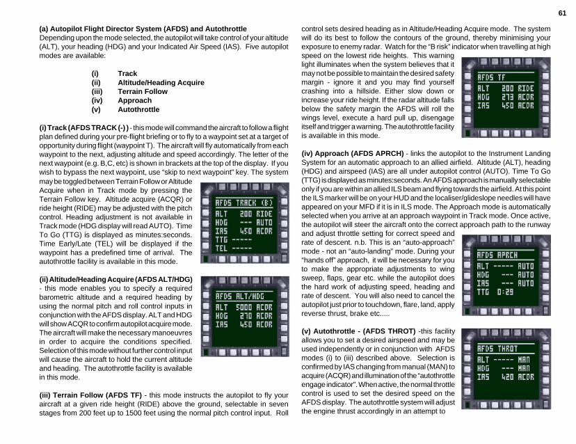
61
(a) Autopilot Flight Director System (AFDS) and AutothrottleDepending upon the mode selected, the autopilot will take control of your altitude(ALT), your heading (HDG) and your Indicated Air Speed (IAS). Five autopilotmodes are available:
(i) Track(ii) Altitude/Heading Acquire(iii) Terrain Follow(iv) Approach(v) Autothrottle
(i) Track (AFDS TRACK (-) ) - this mode will command the aircraft to follow a flightplan defined during your pre-flight briefing or to fly to a waypoint set at a target ofopportunity during flight (waypoint T). The aircraft will fly automatically from eachwaypoint to the next, adjusting altitude and speed accordingly. The letter of thenext waypoint (e.g. B,C, etc) is shown in brackets at the top of the display. If youwish to bypass the next waypoint, use “skip to next waypoint” key. The system
control sets desired heading as in Altitude/Heading Acquire mode. The systemwill do its best to follow the contours of the ground, thereby minimising yourexposure to enemy radar. Watch for the “B risk” indicator when travelling at highspeed on the lowest ride heights. This warninglight illuminates when the system believes that itmay not be possible to maintain the desired safetymargin - ignore it and you may find yourselfcrashing into a hillside. Either slow down orincrease your ride height. If the radar altitude fallsbelow the safety margin the AFDS will roll thewings level, execute a hard pull up, disengageitself and trigger a warning. The autothrottle facilityis available in this mode.
(iv) Approach (AFDS APRCH) - links the autopilot to the Instrument LandingSystem for an automatic approach to an allied airfield. Altitude (ALT), heading(HDG) and airspeed (IAS) are all under autopilot control (AUTO). Time To Go(TTG) is displayed as minutes:seconds. An AFDS approach is manually selectableonly if you are within an allied ILS beam and flying towards the airfield. At this pointthe ILS marker will be on your HUD and the localiser/glideslope needles will haveappeared on your MFD if it is in ILS mode. The Approach mode is automaticallyselected when you arrive at an approach waypoint in Track mode. Once active,the autopilot will steer the aircraft onto the correct approach path to the runwayand adjust throttle setting for correct speed andrate of descent. n.b. This is an “auto-approach”mode - not an “auto-landing” mode. During your“hands off” approach, it will be necessary for youto make the appropriate adjustments to wingsweep, flaps, gear etc. while the autopilot doesthe hard work of adjusting speed, heading andrate of descent. You will also need to cancel theautopilot just prior to touchdown, flare, land, applyreverse thrust, brake etc.....
may be toggled between Terrain Follow or AltitudeAcquire when in Track mode by pressing theTerrain Follow key. Altitude acquire (ACQR) orride height (RIDE) may be adjusted with the pitchcontrol. Heading adjustment is not available inTrack mode (HDG display will read AUTO). TimeTo Go (TTG) is displayed as minutes:seconds.Time Early/Late (TEL) will be displayed if thewaypoint has a predefined time of arrival. Theautothrottle facility is available in this mode.
(ii) Altitude/Heading Acquire (AFDS ALT/HDG)- this mode enables you to specify a requiredbarometric altitude and a required heading byusing the normal pitch and roll control inputs inconjunction with the AFDS display. ALT and HDGwill show ACQR to confirm autopilot acquire mode.The aircraft will make the necessary manoeuvresin order to acquire the conditions specified.Selection of this mode without further control inputwill cause the aircraft to hold the current altitudeand heading. The autothrottle facility is availablein this mode.
(iii) Terrain Follow (AFDS TF) - this mode instructs the autopilot to fly youraircraft at a given ride height (RIDE) above the ground, selectable in sevenstages from 200 feet up to 1500 feet using the normal pitch control input. Roll
(v) Autothrottle - (AFDS THROT) -this facilityallows you to set a desired airspeed and may beused independently or in conjunction with AFDSmodes (i) to (iii) described above. Selection isconfirmed by IAS changing from manual (MAN) toacquire (ACQR) and illumination of the “autothrottleengage indicator”. When active, the normal throttlecontrol is used to set the desired speed on theAFDS display. The autothrottle system will adjustthe engine thrust accordingly in an attempt to

62
maintain the demanded speed. However, pleasenote that this is not possible in all circumstancese.g. in a steep climb or dive or high “g” turn.
Finally, if you disengage the autopilot, pitch androll control revert to manual (MAN) and the MFDwill confirm AFDS OFF if autothrottle is not active,or AFDS THROT if autothrottle is active.
(b) Local MapThis is a moving map display orientated aboutyour present position. The display shows hills,roads, rivers, airfields (active runway in white)and waypoints (B,C,D etc). The map origin maybe toggled between the centre of the display or atthe base of the display. Your aircraft is always atthe map origin, heading along the dottedflightpath. The scale of the map is selectable (i.e.zoom in and out) from 0.5nm, 1nm, 2nm, 4nm,8nm and 16nm with a base origin.
Local Map Mode
(c) Instrument Landing System (ILS)Select this display during your final approach tosee the ILS localiser and glideslope indicators.Additional information on this screen includesaircraft heading (top left corner), bearing to therunway mid-point (top right corner), estimatedtime to touchdown (lower left corner) and distanceto runway mid-point (lower right corner).
(d) RadarThe radar has two independent modes ofoperation,each with on/off control. If the desiredradar mode does not appear as you cycle throughthe MFD functions, first check that the radar isswitched on.
(i) air mode - used for detecting, designating andtracking aircraft. The air radar is a plan viewdisplay showing target range and bearing only.Both enemy and allied aircraft are shown,differentiated by symbology. Use your mouse tomove the designator symbol to coincide with thechosen target and designate with the left mouse
ILS Mode
Air Radar Mode
button. Designation may be cancelled with theright mouse button. If the designator does notappear to respond to the mouse, check that theMFD is the active display for the mouse by pressingthe T key.
The ADV air radar has three selectable ranges: 30 nm (for use with Sky Flash),10nm (for use with AIM9-L) and 2 miles (for use with guns). The IDS radar hasonly the 10nm and 2nm range settings. It is also possible to lock on to a targetvisually through the HUD by using the boresight designate key. Please note thatuse of the radar at very low altitudes will be affected by terrain masking i.e. itcannot see through hills!
(ii) ground mode - used primarily for detecting,designating and tracking military ground vehicles.The display is a composite image of radar returnsand digital map data which are compared toidentify and highlight vehicles. Due to terrainmasking, vehicle returns may be intermittentwhereas mapped features will always be shown.Use your mouse to move the designator symbolto coincide with the chosen target position anddesignate with the left mouse button. Designationmay be cancelled with the right mouse button. Ifthe designator does not appear to respond to themouse, check that the MFD is the active displayfor the mouse by pressing the T key.
The IDS radar has six selectable ranges:0.5nm,1nm, 2nm, 4nm, 8nm and 16nm. The ADV is notfitted with a ground radar.
(e) Forward looking cameraThis display provides a daytime forward view forthe navigator and an image-intensified view forboth crew at night.
Ground Radar Mode
Forward Looking Camera
TV TAB displays (navigator’s cockpit)Both left and right TV TAB displays offer a variety of functions on a mutuallyexclusive basis. Items such as Forward Looking Camera and local map are alsoavailable on the central MFD. Functions are selected by repeatedly pressing theLeft (or Right) Tab Function Select key:
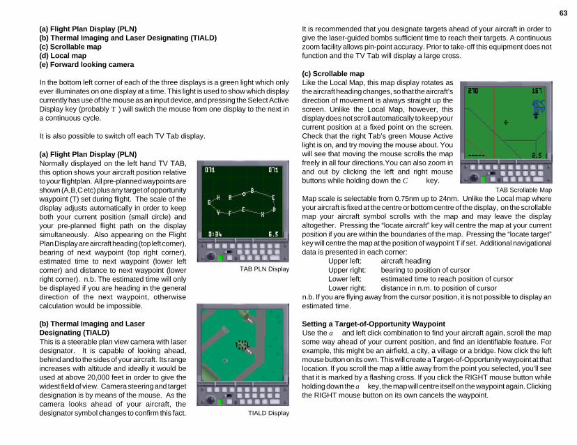
63
(a) Flight Plan Display (PLN)(b) Thermal Imaging and Laser Designating (TIALD)(c) Scrollable map(d) Local map(e) Forward looking camera
In the bottom left corner of each of the three displays is a green light which onlyever illuminates on one display at a time. This light is used to show which displaycurrently has use of the mouse as an input device, and pressing the Select ActiveDisplay key (probably T) will switch the mouse from one display to the next ina continuous cycle.
It is also possible to switch off each TV Tab display.
(a) Flight Plan Display (PLN)Normally displayed on the left hand TV TAB,this option shows your aircraft position relativeto your flightplan. All pre-planned waypoints areshown (A,B,C etc) plus any target of opportunitywaypoint (T) set during flight. The scale of thedisplay adjusts automatically in order to keepboth your current position (small circle) andyour pre-planned flight path on the displaysimultaneously. Also appearing on the FlightPlan Display are aircraft heading (top left corner),bearing of next waypoint (top right corner),estimated time to next waypoint (lower leftcorner) and distance to next waypoint (lowerright corner). n.b. The estimated time will onlybe displayed if you are heading in the generaldirection of the next waypoint, otherwisecalculation would be impossible.
(b) Thermal Imaging and LaserDesignating (TIALD)This is a steerable plan view camera with laserdesignator. It is capable of looking ahead,behind and to the sides of your aircraft. Its rangeincreases with altitude and ideally it would beused at above 20,000 feet in order to give thewidest field of view. Camera steering and targetdesignation is by means of the mouse. As thecamera looks ahead of your aircraft, thedesignator symbol changes to confirm this fact. TIALD Display
TAB PLN Display
It is recommended that you designate targets ahead of your aircraft in order togive the laser-guided bombs sufficient time to reach their targets. A continuouszoom facility allows pin-point accuracy. Prior to take-off this equipment does notfunction and the TV Tab will display a large cross.
(c) Scrollable mapLike the Local Map, this map display rotates asthe aircraft heading changes, so that the aircraft’sdirection of movement is always straight up thescreen. Unlike the Local Map, however, thisdisplay does not scroll automatically to keep yourcurrent position at a fixed point on the screen.Check that the right Tab’s green Mouse Activelight is on, and try moving the mouse about. Youwill see that moving the mouse scrolls the mapfreely in all four directions.You can also zoom inand out by clicking the left and right mousebuttons while holding down the C key.
Map scale is selectable from 0.75nm up to 24nm. Unlike the Local map whereyour aircraft is fixed at the centre or bottom centre of the display, on the scrollablemap your aircraft symbol scrolls with the map and may leave the displayaltogether. Pressing the “locate aircraft” key will centre the map at your currentposition if you are within the boundaries of the map. Pressing the “locate target”key will centre the map at the position of waypoint T if set. Additional navigationaldata is presented in each corner:
Upper left: aircraft headingUpper right: bearing to position of cursorLower left: estimated time to reach position of cursorLower right: distance in n.m. to position of cursor
n.b. If you are flying away from the cursor position, it is not possible to display anestimated time.
Setting a Target-of-Opportunity WaypointUse the a and left click combination to find your aircraft again, scroll the mapsome way ahead of your current position, and find an identifiable feature. Forexample, this might be an airfield, a city, a village or a bridge. Now click the leftmouse button on its own. This will create a Target-of-Opportunity waypoint at thatlocation. If you scroll the map a little away from the point you selected, you’ll seethat it is marked by a flashing cross. If you click the RIGHT mouse button whileholding down the a key, the map will centre itself on the waypoint again. Clickingthe RIGHT mouse button on its own cancels the waypoint.
TAB Scrollable Map
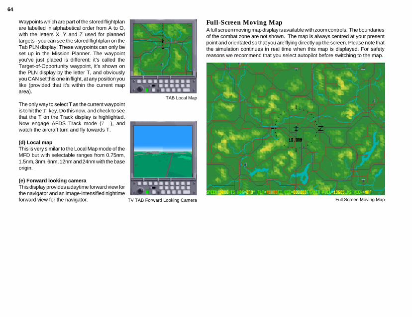
64
TAB Local Map
TV TAB Forward Looking Camera
Waypoints which are part of the stored flightplanare labelled in alphabetical order from A to O,with the letters X, Y and Z used for plannedtargets - you can see the stored flightplan on theTab PLN display. These waypoints can only beset up in the Mission Planner. The waypointyou’ve just placed is different; it’s called theTarget-of-Opportunity waypoint, it’s shown onthe PLN display by the letter T, and obviouslyyou CAN set this one in flight, at any position youlike (provided that it’s within the current maparea).
The only way to select T as the current waypointis to hit the T key. Do this now, and check to seethat the T on the Track display is highlighted.Now engage AFDS Track mode (7), andwatch the aircraft turn and fly towards T.
(d) Local mapThis is very similar to the Local Map mode of theMFD but with selectable ranges from 0.75nm,1.5nm, 3nm, 6nm, 12nm and 24nm with the baseorigin.
(e) Forward looking cameraThis display provides a daytime forward view forthe navigator and an image-intensified nightimeforward view for the navigator.
Full-Screen Moving MapA full screen moving map display is available with zoom controls. The boundariesof the combat zone are not shown. The map is always centred at your presentpoint and orientated so that you are flying directly up the screen. Please note thatthe simulation continues in real time when this map is displayed. For safetyreasons we recommend that you select autopilot before switching to the map.
Full Screen Moving Map

65
TECHNICAL SUPPLEMENT
Preferences
IBM PCBy selecting the Preferences icon on the main screen, you may:a) preset simulation preferencesb) specify sound hardware and which sound effects you wish to hearc) specify or recalibrate your joystickd) specify your preferences on several miscellaneous features.
Joystick selection and calibrationTornado will automatically detect how many analog joysticks you have connectedi.e. either one or two. If you believe that the program is not detecting a joystick,first check that the trim controls on the joystick are centred. If you have aThrustmaster FCS joystick, click the appropriate button. The program will requireyou to calibrate theThrustmaster joystick and itscoolie hat by moving it to fulltravel and then back to centre.This procedure will only benecessary once providingthat you save yourpreferences. All other typesof joystick may be calibratedat any time during thesimulation by centering thejoystick and pressing Y.Certain joysticks may needto be used on the “highsensitivity” setting in order toachieve better aircraftmanoeuvrability but pleaseremember that a Tornado isnot an F-16!
Miscellaneous preferencesWe have introduced one extra option - Night Level. When this option is “Free”,all four night levels will occur i.e. from dusk to pitch black. In normal ambientlighting conditions, the darker levels (3 and 4) can make the game difficult to play.By setting this option to “Fixed”, only levels 1 and 2 will be used by the program.
Remember to save your preferences if you decide to change any of them.
Two Player
IBM PCThis option allows you to link two computers via modem or a direct cable link andfly head-to-head combat with a friend. You will need a copy of Tornado on bothcomputers.
Access to Two Player mode is via the Combat screen:1 At the Main Screen, select Flight2 On the next screen, select Combat3 On the next screen, select Two Player
Set-upa) Connection via a modemPlease note that playing the Two Player option over a modem will be charged asa telephone call at a rate appropriate to the charge band. Please seek permissionif you are not the owner of the phone.
The modem interface supports any Hayes-compatible modem (AT commands)that is capable of at least 2400/2400 baud (V22 bis 2400).
To use a modem for two player missions, proceed as follows:1 Connect the modem to either COM1 or COM2 serial port and then select theappropriate port by clicking on COM1 or COM2 button.2 Click on the “modem” button to enable the modem controls, open the dialoguebox and initialize it. The dialogue box will display “Initialize modem” followed byOK if successful. If a problem occurs you will see a message e.g. “transmissionerror” or “no reply, reset modem and retry” - see fault finding below.3 Select the two player menu options for weather, start time, range, difficulty, andRED or BLUE leader.4 Decide which player will be the “caller”. The other player will be the “receiver”.5 For the caller to dial a number, click on the “Phone no.” button, enter the number(see your modem manual for any special command characters) followed byE.6 Select Tone or Pulse dialling and then click on the Dial button. The dialoguebox will say “dialling number” followed by “CONNECT nnnn” if successful, wherennnn is the baud rate. Possible errors are:i) “No dial tone” - check that your modem is connected to the phone lineii) “Busy” - line is engagediii) “No answer” - receiver not respondingiv) “No carrier” - receiver’s phone is answering but his modem not responding
NEW.PM5 10/1/96, 9:39 AM65

66
3 Did you dial the wrong number? Select “Hang-up” and retry.4 Have you selected the correct COM port. Check to see which port your cableor modem is plugged into.5 Are you clear about who is the “caller” and who is the “receiver”? If you bothtry to be “caller” you will get nowhere.6 If your phone has a “call waiting” facility, this may disrupt the modem connectionduring your game. It should be possible to temporarily disable this feature priorto starting your game. Check in your phone handbook.
b) Direct link using null modem cableIf you intend to use a direct cable link, a “null modem” cable must be connectedinto a serial port on each computer. For pin connections, see diagram. The plugson the end of your null modem cable must match the ports of both computers. Theports will either be 9-pin or 25-pin, and will probably be male (pins).
If you do not have a null modem cable, you may order one direct from DigitalIntegration sales on 0276 684959. Check the ports on both computers beforeordering your cable. As you can see from the diagram, there are three possibleconfigurations for your cable.
Please note that you do not need amodem in order to use a “null modem”cable. Just plug one end of the cableinto a spare serial port (e.g. COM1) onone of the computers and plug the otherend into a spare serial port (e.g. COM1)on the other computer. The length ofthe cable will limit how far apart you canphysically place the computers, for upto a maximum of several hundred feet.Proceed as follows:1 On the BAUD/PORT window, specifythe baud rate and serial port you wish touse. The same baud rate must be usedon each computer. For PC users, selectthe port in use i.e. COM1 or COM2.2 Make your menu selection (see below)3 Decide who will be Red leader andBlue Leader.4 Click on START picture.5 A dialogue box will be opened toannounce “Testing link” followed by“Transmitting menu data”. When bothsystems have been initialised with
See below for other error messages.7 The receiver may use either “auto-answer” or “manual answer”. For auto-answer, click on the “auto-answer” button and wait for the phone to ring. Thedialogue box will say “”Awaiting call”, followed by “RING” and “CONNECT nnnn”when the phone has rung and connection has been established. Alternatively,if you wish to use “manual answer”, click on the “manual answer” button when thephone rings.8 As soon as communication between the computers is established, the dialoguebox will print “Testing link”. When both systems are ready, start conditions will beconfirmed and the game will begin.9 To abort a call once connection has been made, click on the “hang up” button.The dialogue box will confirm this by printing “Hang up phone” followed by OK ifsuccessful.10 The “Command” button is provided to enable you to send commands to themodem to reconfigure it , check its status, etc. To send a command, click on thebutton, enter the command, and then press E. Clicking on the button willabort entry and the command will not be sent.11 Any commands that involve a long timeout period may be aborted by pressingany key.
Fault finding when using the modemModem messages.These are the same as the standard Hayes messages with the followingadditions:“Unexpected response” expecting OK but got a different response.“Unrecognised response” not a recognised Hayes response.“Transmission error” serial communication problem.“Timeout error” no response from modem.“Key pressed, aborted” User aborted.
All errors described for direct link operation also apply.
Problems1 If the modem is not responding:a) Check all connections and that the modem is switched on.b) The modem may be in “quiet” mode. The modem controller has been writtenwith a smart receiver which will allow the modem to be in half or full duplex mode,with short form or verbose responses, but it cannot cope with quiet mode “ATQ1”.Try cancelling this mode by sending “ATQ0” command.2 Communication errors when “Testing link”:a) Both users should try to re-establish the link by clicking on the START picture.b) Have you selected a BAUD rate that is compatible with your modem?c) Try using the lowest baud rate e.g. 2400
NEW.PM5 10/1/96, 9:39 AM66

67
common start conditions, the message “Common menu values set” is printed,followed by “Take-off” after a short delay to enable you to see the conditions.6 “Testing link” may be aborted by pressing any key.
Fault finding when using direct link1 Are the pin connections correct on your cable? Check the diagram.2 Have you both selected the same BAUD rate?
Error messages:1 Timeout - one or both computers are not receiving data. The possible causesare:i) Computers not connected to each otherii) Cable connected to the wrong serial port or incorrect serial port selectediii) Faulty cableiv) Different baud rates selectedv) More than 30 seconds had elapsed between both players selecting START2 Transmission error - this is caused by data corruption, possibly due to anexcessively long cable or an “electronically noisy” environment. Try re-routingthe cable.3 Checksum error - see Transmission error.4 Error - both RED leader or both BLUE leader. Both players have selected thesame option. One player must change.
Two player menu selectionsBoth players should select the same start conditions on the GAME window:
Weather: Light cloud orOvercast orLight fog orThick fog
Time: 8am to 6pm day6pm to 8pm night level 1 - dusk8pm to 10pm night level 210pm to 12pm night level 312pm to 2am night level 4 (darkest)2am to 4am night level 34am to 6am night level 26am to 8am night level 1 - dawn
The take-off time dictates the light level which does not change during flight.
Opponent: In visual range orBeyond visual range
Cheats: ON or OFF
This option offers infinite fuel, maximum manoeuvrability, no G-LOC, 10 SkyFlash, 10 Sidewinders and infinite cannon. If identical conditions are notselected, the computer will set both players to the more difficult condition of thetwo.
The objective of the game is simple - shoot down your opponent. As each playersucceeds, the game will pass to the Debrief screen to present the score. Eitherplayer may then elect to continue the game or quit. At this point, modem userswill be confirmed as “Off Line”. Details of Two Player operation cannot be storedin your Pilot’s Log.
Faulty items
If you purchased Tornado direct from Digital Integration and you are unhappywith the product for any reason, it is our company policy to offer a full refundproviding that the product is returned to us in a re-saleable condition within 14days of purchase. If you are having trouble with installation then please call orwrite to Customer Support. If you suspect that any of the discs are faulty, pleasereturn just the discs to Customer Support and we will exchange the items fortested replacements. We regret that it is not possible for us to offer full refundsto customers who purchased any of our products from retailers or mail ordercompanies. In these cases, your request must be addressed to the vendor.
ERRATA AND ADDITIONS
Last minute additions...• p 28 - 2nd para. - There are no keystrokes that may be substituted for mousecommands in the Review mode.• The q key may be used instead of the Exit button when in the Mission Planner.• Pressing keys S and 5 together will reverse cycle through the computercontrolled aircraft.• Explore mode in Debrief - introduced so that you can evaluate target areadamage before leaving the Debrief screen.• Only the player’s aircraft can use loft delivery mode or ALARM in direct mode.Computer-controlled allied aircraft do not have this capability.• When AA is selected on the Mission Planner KEY, the small circles representAAA threats and the larger circles represent SAM threats.• When in the Mission Planner you may notice slight delays when closingwindows. This phenomenon is due to the Mission Planner performing numerouscalculations in parallel to your planning. The effect is more noticeable on slowermachines and is quite normal. This parallel computation can also temporarilyinhibit movement of the mouse pointer.
NEW.PM5 10/1/96, 9:39 AM67
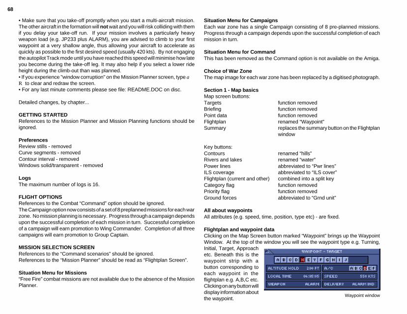
68
• Make sure that you take-off promptly when you start a multi-aircraft mission.The other aircraft in the formation will not wait and you will risk colliding with themif you delay your take-off run. If your mission involves a particularly heavyweapon load (e.g. JP233 plus ALARM), you are advised to climb to your firstwaypoint at a very shallow angle, thus allowing your aircraft to accelerate asquickly as possible to the first desired speed (usually 420 kts). By not engagingthe autopilot Track mode until you have reached this speed will minimise how lateyou become during the take-off leg. It may also help if you select a lower rideheight during the climb-out than was planned.• If you experience "window corruption" on the Mission Planner screen, type aR to clear and redraw the screen.• For any last minute comments please see file: README.DOC on disc.
Detailed changes, by chapter...
GETTING STARTEDReferences to the Mission Planner and Mission Planning functions should beignored.
PreferencesReview stills - removedCurve segments - removedContour interval - removedWindows solid/transparent - removed
LogsThe maximum number of logs is 16.
FLIGHT OPTIONSReferences to the Combat “Command” option should be ignored.The Campaign option now consists of a set of 8 preplanned missions for each warzone. No mission planning is necessary. Progress through a campaign dependsupon the successful completion of each mission in turn. Successful completionof a campaign will earn promotion to Wing Commander. Completion of all threecampaigns will earn promotion to Group Captain.
MISSION SELECTION SCREENReferences to the “Command scenarios” should be ignored.References to the “Mission Planner” should be read as “Flightplan Screen”.
Situation Menu for Missions“Free Fire” combat missions are not available due to the absence of the MissionPlanner.
Situation Menu for CampaignsEach war zone has a single Campaign consisting of 8 pre-planned missions.Progress through a campaign depends upon the successful completion of eachmission in turn.
Situation Menu for CommandThis has been removed as the Command option is not available on the Amiga.
Choice of War ZoneThe map image for each war zone has been replaced by a digitised photograph.
Section 1 - Map basicsMap screen buttons:Targets function removedBriefing function removedPoint data function removedFlightplan renamed “Waypoint”Summary replaces the summary button on the Flightplan
window
Key buttons:Contours renamed “hills”Rivers and lakes renamed “water”Power lines abbreviated to “Pwr lines”ILS coverage abbreviated to “ILS cover”Flightplan (current and other) combined into a split keyCategory flag function removedPriority flag function removedGround forces abbreviated to “Grnd unit”
All about waypointsAll attributes (e.g. speed, time, position, type etc) - are fixed.
Flightplan and waypoint dataClicking on the Map Screen button marked “Waypoint” brings up the WaypointWindow. At the top of the window you will see the waypoint type e.g. Turning,Initial, Target, Approachetc. Beneath this is thewaypoint strip with abutton corresponding toeach waypoint in theflightplan e.g. A,B,C etc.Clicking on any button willdisplay information aboutthe waypoint.
Waypoint window
NEW.PM5 10/1/96, 9:39 AM68

69
Beneath the waypoint strip are four boxes displaying autopilot mode (e.g. terrainfollowing, altitude hold), aircraft number and letter (e.g. 017 A,B,C), local time(planned time of arrival at waypoint) and speed (planned speed over the legleading to the waypoint).
Two additional boxes appear in the waypoint window for target waypoints and theapproach and take off waypoints:
Target Weapon weapon type e.g. 1000 lb GPBDelivery delivery mode e.g. loft, laydown
Approach Head wind wind component along runway when landing& take off Cross wind wind component across runway when landing
It is not possible to introduce additional waypoints or to change the flightplan inany way.
The Flightplan Profile feature is not available.
AIRCREW NOTESKneepad view5 Horizon - function not available6 HUD frame - renamed “ironwork”7 Control device (port 2) - options include digital joystick or analogue joystick orsecond mouse.
PC Trouble Shooting
1) JOYSTICKa) Keep your hand off the joystick when selecting Take-Off. Once on the runwaythe computer will have re-calibrated the joystick for you.b) If you have a joystick port on your soundcard as well as an individual joystickcard make sure that the joystick port on the sound board is disabled.c) If you are using a single joystick on a dual joystick card, then use Port 1.d) Ensure Trim Wheels are set to centre position.e) When using an intelligent games card e.g. Quickshot Smart Card, pleaseensure that the appropriate software driver is loaded. Modify your boot disc asnecessary.
2) SOUND CARDa) SoundBlaster Pro - The DMA has to be set to 1.b) SoundBlaster & SBPro - IRQ in general should be 7, however if problemsoccur try 2, 3 or 5.c) If the sound effects are intermittent when using soundBlaster, use the adliboption.
3) WARNING MESSAGESProblem message “warning***..\dataxchg\layer.in”Reason Not enough files in CONFIG.SYSAnswer Set Files = 15 and Buffers = 20 in CONFIG.SYSProblem message "warning ***..\tripleA\samdata"Reason Not enough space on hard disc.Answer Free up at least 1 MB of space (make sure Files=15 in
CONFIG.SYS)
4) MSDOS 6.0If you are using DBLSPACE with MSDOS 6.0 either with your original set up ora boot disk you will need to load DBLSPACE high. Add or adjust the followingline in your CONFIG.SYS.
devicehigh=c:\dos\dblspace.sysWhen not using the boot disc make sure Files & Buffers are set to at least Files=15and Buffers=20.
5) DRDOS 6.0If your DRDOS 6.0 version is dated 08/91 you will need to update to at least 04/92. Make sure that you have a fully DRDOS 6.0 compatible mouse driver.
When not using the boot disc make sure Files & Buffers are set to at least Files=15and Buffers=20. The Tornado boot disc does not cater for DRDOS 6.0 at themoment, so the CONFIG.SYS and AUTOEXEC.BAT should be edited for theboot disc as follows:CONFIG.SYSDevice=C:\drdos\emm386.sys
/F=none /K=auto /B=ffff /R=auto** Device=C:\sstordrv.sys /hidma** Device=C:\devswap.comHidos=onFiles=15Buffers=20** omit these lines if not usingSuperStor.
6) MICROSOFTMOUSE DRIVER V.9Tornado will not work with this Mouse driver. Use an earlier version.
AUTOEXEC.BAT*** Set mouse=C:\mouse*** C:\mouse\mouse.comC:CD C:\tornadocall tornado.bat.*** Modify according to location ofmouse driverNOTE: you will also need to edit yourtornado.bat file. Line 4 at presentreads...Loadhigh Amp. For DRDOS6.0 replace with HiLoad Amp.
NEW.PM5 10/1/96, 9:39 AM69

70
Tornado README file
Please registerSend in your pre-paid registration card to ensure that you receive details ofproduct updates and special offers.
Tips1 Enemy interceptors will have difficulty tracking you if you are terrain followingat low altitude and at high speed. This may mean breaking formation temporarilyto fly ahead and your route may no longer match the flightplan due to the widerturns at each waypoint.2 Take particular care when terrain following at high speed with 67° wing sweep.3 When landing with a high crosswind, you may find that the auto-approachsystem cannot remain centred in the ILS beam. This is when all that practice atmanual landing comes in handy…
CUSTOMER SUPPORT
If you have any questions about Tornado or any of our other products, pleasecontact Customer Support at:
write Digital Integration LtdWatchmoor Trade CentreWatchmoor RoadCamberleySurrey, GU15 3AJ
phone 0276 678806 (UK only)Between 2pm and 5pm, Monday to Friday
email address [email protected]
It helps us enormously if you have already returned your registration card butplease be prepared to provide the following information:
NameAddressProduct nameComputerDescription of problem and how it occurredError messages appearing on screen
NEW.PM5 10/1/96, 9:39 AM70

71
NEW.PM5 10/1/96, 9:39 AM71
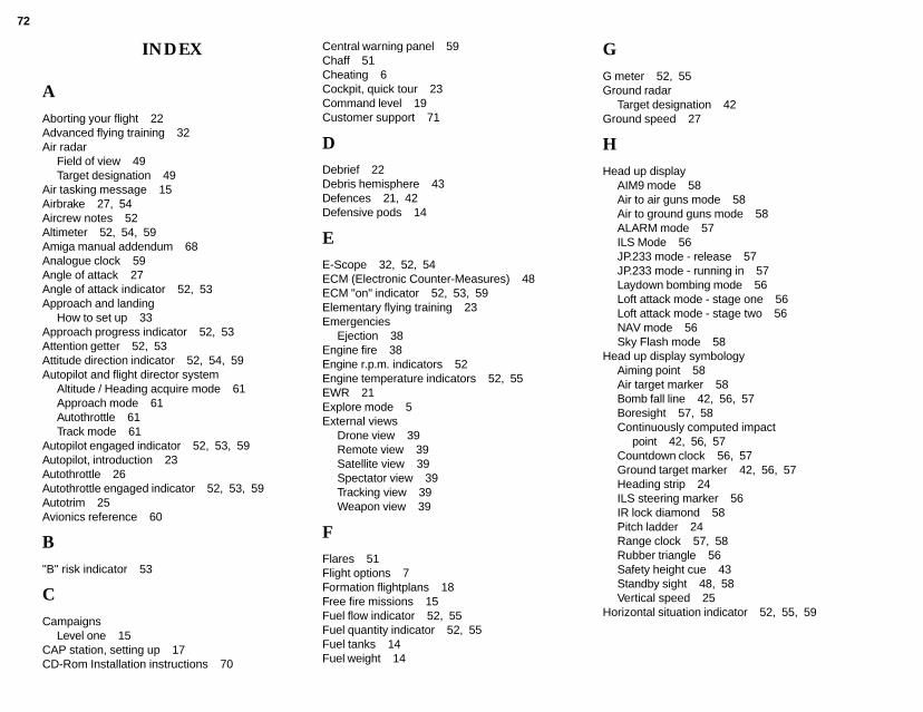
72
INDEX
AAborting your flight 22Advanced flying training 32Air radar
Field of view 49Target designation 49
Air tasking message 15Airbrake 27, 54Aircrew notes 52Altimeter 52, 54, 59Amiga manual addendum 68Analogue clock 59Angle of attack 27Angle of attack indicator 52, 53Approach and landing
How to set up 33Approach progress indicator 52, 53Attention getter 52, 53Attitude direction indicator 52, 54, 59Autopilot and flight director system
Altitude / Heading acquire mode 61Approach mode 61Autothrottle 61Track mode 61
Autopilot engaged indicator 52, 53, 59Autopilot, introduction 23Autothrottle 26Autothrottle engaged indicator 52, 53, 59Autotrim 25Avionics reference 60
B"B" risk indicator 53
CCampaigns
Level one 15CAP station, setting up 17CD-Rom Installation instructions 70
Central warning panel 59Chaff 51Cheating 6Cockpit, quick tour 23Command level 19Customer support 71
DDebrief 22Debris hemisphere 43Defences 21, 42Defensive pods 14
EE-Scope 32, 52, 54ECM (Electronic Counter-Measures) 48ECM "on" indicator 52, 53, 59Elementary flying training 23Emergencies
Ejection 38Engine fire 38Engine r.p.m. indicators 52Engine temperature indicators 52, 55EWR 21Explore mode 5External views
Drone view 39Remote view 39Satellite view 39Spectator view 39Tracking view 39Weapon view 39
FFlares 51Flight options 7Formation flightplans 18Free fire missions 15Fuel flow indicator 52, 55Fuel quantity indicator 52, 55Fuel tanks 14Fuel weight 14
GG meter 52, 55Ground radar
Target designation 42Ground speed 27
HHead up display
AIM9 mode 58Air to air guns mode 58Air to ground guns mode 58ALARM mode 57ILS Mode 56JP.233 mode - release 57JP.233 mode - running in 57Laydown bombing mode 56Loft attack mode - stage one 56Loft attack mode - stage two 56NAV mode 56Sky Flash mode 58
Head up display symbologyAiming point 58Air target marker 58Bomb fall line 42, 56, 57Boresight 57, 58Continuously computed impact
point 42, 56, 57Countdown clock 56, 57Ground target marker 42, 56, 57Heading strip 24ILS steering marker 56IR lock diamond 58Pitch ladder 24Range clock 57, 58Rubber triangle 56Safety height cue 43Standby sight 48, 58Vertical speed 25
Horizontal situation indicator 52, 55, 59
NEW.PM5 10/1/96, 9:39 AM72

73
IILS display 35Indicated airspeed / Mach
number 27, 52, 54, 59Installing and Running Tornado 3Instrument panel
Navigator 59Pilot 52
JJettison indicator lights 52, 54
KKey, mission planner 9Kneepad view 60
LLanding
Automated 29Manual 36Semi-automatic 35Wind direction 37
Landing damaged aircraft 37Landing gear position indicator 52, 59Landing practice for auto-approach 29Late arm switch 52, 53Level turns 25Look down view 60
MMach number 27, 28Manoeuvre drag 27Map screen buttons 9
Briefing 9Centre 9Fit 9Flight plan 9Key 9Met. report 9Payload 9
Point data 9Take-off 9Targets 9Tidy 9
Met. report 13Missile countermeasures 51Missiles, effective range 51Mission planner 9Mission rehearsal 13Mission selection screen 8Mouse active indicator 52, 59Multi function display
Forward looking camera 62Local map 62Radar 62
NNegative g, effects of 26
OOptions.../Exit Buttons 4Oxygen flow indicator 52
PPayload window 13PC Trouble Shooting 69Positive g, effects of 26Preferences 65
Contour interval 5Control device 4Curve segments 5Ground detail 4Hill texture 4Horizon, graduated 4Ironwork 4Panel lighting 5Review stills 5Sky, clouds 4Sound and music 5Visual range 4Windows 5
Protection (PC version) 65
RRadar
Air mode 49, 62Ground mode 62
Radar altimeter 52, 54Radar "on" indicator 52, 53, 59Radar warning receiver 51, 52, 55Recalibrate joystick 4Reheat 30Reheat operating lights 52, 53Reverse thrust indicators 52, 53Review 5
SSecondary control surfaces position indica-
tor 52, 53Simulator options 8Situation menu 8Skipping waypoints 33Speeds, fixed, free and bound 17Spin recovery 38Stalling 27Standby compass 52, 55Stores management display 41, 59System Requirements 3
TTaking off 30–31Target classes
Battlefield 21Command 20Counter air 21Logistics 20–21Politics 21
Target finder 16Target of opportunity
Designating on ground radar 42Target-of-opportunity waypoint 63Terrain following 32Terrain masking 62Thrust reversers 30
NEW.PM5 10/1/96, 9:39 AM73
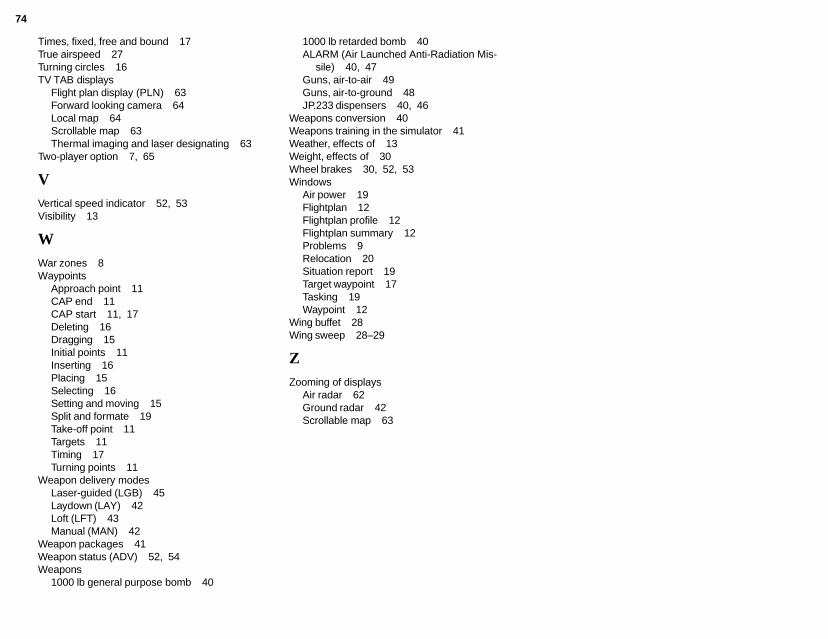
74
Times, fixed, free and bound 17True airspeed 27Turning circles 16TV TAB displays
Flight plan display (PLN) 63Forward looking camera 64Local map 64Scrollable map 63Thermal imaging and laser designating 63
Two-player option 7, 65
VVertical speed indicator 52, 53Visibility 13
WWar zones 8Waypoints
Approach point 11CAP end 11CAP start 11, 17Deleting 16Dragging 15Initial points 11Inserting 16Placing 15Selecting 16Setting and moving 15Split and formate 19Take-off point 11Targets 11Timing 17Turning points 11
Weapon delivery modesLaser-guided (LGB) 45Laydown (LAY) 42Loft (LFT) 43Manual (MAN) 42
Weapon packages 41Weapon status (ADV) 52, 54Weapons
1000 lb general purpose bomb 40
1000 lb retarded bomb 40ALARM (Air Launched Anti-Radiation Mis-
sile) 40, 47Guns, air-to-air 49Guns, air-to-ground 48JP.233 dispensers 40, 46
Weapons conversion 40Weapons training in the simulator 41Weather, effects of 13Weight, effects of 30Wheel brakes 30, 52, 53Windows
Air power 19Flightplan 12Flightplan profile 12Flightplan summary 12Problems 9Relocation 20Situation report 19Target waypoint 17Tasking 19Waypoint 12
Wing buffet 28Wing sweep 28–29
ZZooming of displays
Air radar 62Ground radar 42Scrollable map 63
NEW.PM5 10/1/96, 9:39 AM74


