104


THE UNIVERSITY
OF ILLINOIS
LIBRARY


TORQUE CHARACTERISTICS
OF VARIOUS TYPES OF ELECTRIC MOTORS
BY
HARRY FOREST GEIST
THESIS
FOR THE
DEGREE OF BACHELOR OF SCIENCE
IN
ELECTRICAL ENGINEERING
COLLEGE OF ENGINEERING
UNIVERSITY OF ILLINOIS
1912

\%\tl
i
I

UNIVERSITY OF ILLINOIS
THIS IS TO CERTIFY THAT THE THESIS PREPARED UNDER MY SUPERVISION BY
HARRY HffiEfflE 0,3 1ST „
ENTITLED TORQUE CHARACTERISTICS
QF VARIOUS. TYPES OP BfrgggRie MOTORS
IS APPROVED BY ME AS FULFILLING THIS PART OF THE REQUIREMENTS FOR THE
DEGREE OF BACHELOR OF SC I 3ITC7, TIT ^CTRTCAI ^THE^I^O
APPROVED:
Instructor in Charge
HEAD OF DEPARTMENT OF EL3CTRTCAL EJ 1 G IHM T B 6 .


TABLE 0? CONTENTS
PagesPreface 1 - 3
Purpose of thesisScope of thesis
IntroductionElectromagnetic Transformation of Electrical to
Mechanical Energy 3 - 6
Explanation of effect of current carry-ing conductors in a magnetic field
Chapter I
Direct Current Motors 6 - 12Application of Chapter I to direct cur-
rent motors, including the deriva-tion of all fundamental formulae
Chapter IIShunt D. C. Motor 12 - 23
Study of characteristics of shunt motor,especially the relations "between cur-rent, torque, and speed, with exampleand graphs.
Chapter IIISeries D. C. Motor 23 - 33
Same treatise as for shunt motor
Chapter IVCompound D. C. Motor 33 - 35
Relation of compound to series and shuntmotors
Chapter VPolyphase Induction Motor 35 - 55
Study of principles, formulae, and charac-teristics of a polyphase inductionmotor, especially those relative totorque, including example and graphs
Summary 55 - endConclusions from study in previous chap-
ters on torque relations for thedifferent types of motor considered,and comparisons and contrasts "betweenthem by graphs
I

Digitized by the Internet Archive
in 2013
http://archive.org/details/torquecharacteriOOgeis
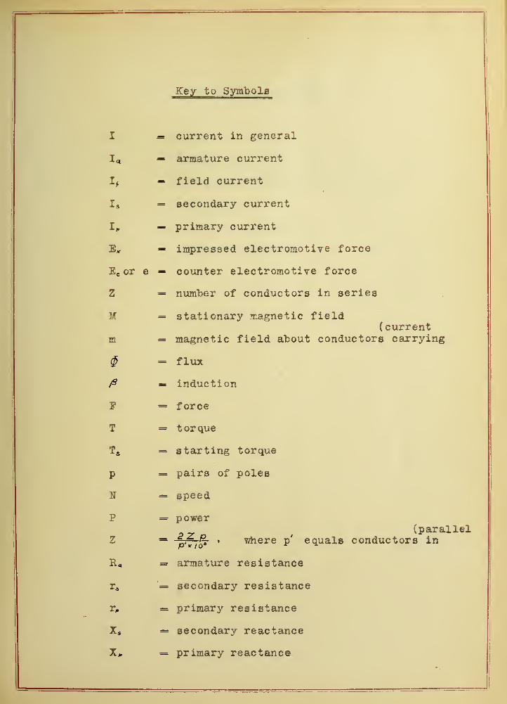
Key to Symbols
I current in general
T*>« armature currentCAX UiM> V L*X V* \J VAX A vU w
Tr field current
I--** s secondary current
primary current
Ex- imnressed electromotive force
it, or e V> W VAxx vvx v X v v v V/lli v/ vX V v X V* W v
zSii number of conductors in series
M
ill
= stationary magnetic field( current
mafriptir field about conductors carrvinerXXXCX pi 1 X *j X W j. X W X.U M W wX. W V* W X X -X. LAV V W J- V 1A«*» « X X
<$ flux
iridur "fci on
P force
T t or que
T«*s starting toraue
T) pairs of poles
N speed
P
Z
power
;
(parallel*L .fi- ' where p' equals conductors in
R- armature resistance
secondary resistance
primary resistance
•* s secondary reactance
= primary reactance
1


Key to Symbols (continued )
S = slip
g = admittance to coreloss current
b = admittance to magnetizing current
f = frequency
Z 5 = secondary impedance
Z„ = primary impedance

1
PREFACE
The purpose of this thesis is to study the torque
of the direct current shunt motor, of the direct current series
motor, and of the alternating current polyphase induction motor.
The scope of the thesis will be a complete study of
the fundamental principles of -the machines under consideration,
derivation of the fundamental formulae, and to show by calcu-
lated results and graphs the relation between load, current,
torque, speed, losses, and efficiency, with special attention
to the relations of torque and current.
Besides the true efficiency, which equals the input
minus losses divided by input, the torque efficiency will be
considered in connection with torque. True efficiency is cal-
culated from the consideration of the losses, while torque ef-
ficiency, which by definition equals starting torque times
normal speed divided by power input involved, will be calcu-
lated from torque, arid comparison made by graphs between true
efficiency and torque efficiency as well as between running
torque and starting torque.
The study of torque and its relation to speed and
power developed is a very helpful one to the electrical engi-
neer, because of the wide field in the industrial world for
electric motors. The intelligent application of motors must
be based upon a thorough knowledge of what the machine will do
under all conditions, and this behavior can best be determined


2
by a study of characteristics. A thorough knowledge of torque
and the factors that produce it and their relation to highest
perfection in motors is also of importance to the designing
engineer. It is with these things in mind that I respectfully
submit this thesis. „ / orr


3
INTRODUCTION
Electro-magne tic Transformation of Electrical
to Mechanical Energy
If a current "I" is forced through a conductor by
an electromotive force "Ex", a magnetic field "m M will "be set
up around the conductor. This field will encircle the con-
ductor in a direction depending upon the direction of the cur-
rent through the conductor. The rotation is clockwise with a
receding current, and vice versa as shown "by diagram #1.
Diagram #1
If the conductor is placed in another magnetic
field "H" , and no current forced through it, the field MM" will
not he disturbed, except for the slight difference in permea-
bility of the conductor material and that through which MM"
flows. But by forcing a current through the conductor, the
added effects of "M" and "m" cause a distorted field, as is
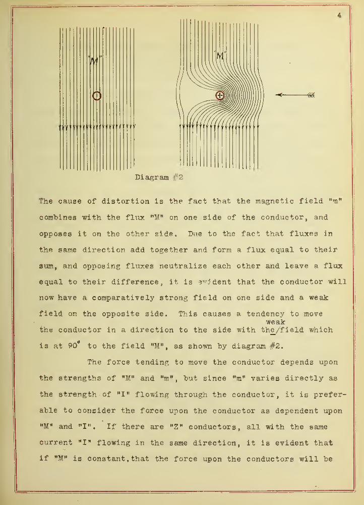
shown by diagram #2.

4
Diagram $2
The cause of distortion is the fact that the magnetic field "m"
combines with the flux MM M on one side of the conductor, and
opposes it on the other side. Due to the fact that fluxes in
the same direction add together and form a flux equal to their
sum, and opposing fluxes neutralize each other and leave a flux
equal to their difference, it is evident that the conductor will
now have a comparatively strong field on one side and a weak
field on the opposite side. This causes a tendency to moveweak
the conductor in a direction to the side with the_/field which
is at 90° to the field "M", as shown "by diagram #2.
The force tending to move the conductor depends upon
the strengths of "M" and wm", hut since "m" varies directly as
the strength of "I" flowing through the conductor, it is prefer-
able to consider the force upon the conductor as dependent upon
"M" and M I" . If there are "Z M conductors, all with the same
current "I" flowing in the same direction, it is evident that
if "M" is constant , that the force upon the conductors will be
B
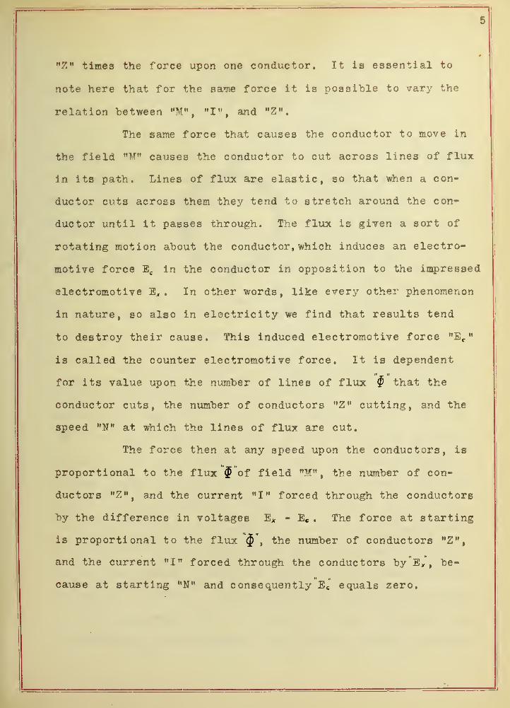
"Z" times the force upon one conductor. It is essential to
note here that for the same force it is possible to vary the
relation between "M",
"I", and "Z".
The same force that causes the conductor to move in
the field "If" causes the conductor to cut across lines of flux
in its path. Lines of flux are elastic, so that when a con-
ductor cuts across them they tend to stretch around the con-
ductor until it passes through. The flux is given a sort of
rotating motion about the conductor, which induces an electro-
motive force Ec in the conductor in opposition to the impressed
electromotive E„ . In other words, like every other phenomenon
in nature, so also in electricity we find that results tend
to destroy their cause. This induced electromotive force "E c"
is called the counter electromotive force. It is dependent
for its value upon the number of lines of flux $ that the
conductor cuts, the number of conductors "Z" cutting, and the
speed "N" at which the lines of flux are cut.
The force then at any speed upon the conductors, is
proportional to the flux $ of field "M" , the number of con-
ductors "Z", and the current "I" forced through the conductors
by the difference in voltages Ex - Ee . The force at starting
is proportional to the flux $*, the number of conductors "Z",
and the current "I" forced through the conductors by"E x", be-
cause at starting "N" and consequently E c equals zero.


6
CHAPTER I
Direct Current Motors
Diagram #3
The above diagram is a simple representation of the
practical application of the transformation of electrical to
mechanical energy as used in direct current motors. The flux
of field "M" passes from the iron core of the north pole,
through an air gap, across the armature core and conductors,
through another air gap, into the core of the south pole, and
hack to the north pole by an iron yoke not shown in diagram.
The flux is set up by a conductor wound about the field core
projections. Its strength depends upon the number of turns,
the current flowing through the turns, and the permeability of
the magnetic circuit. The armature is an iron cylinder mounted
upon an axis, about which' it is free to rotate. The conductors
are wound upon the cylinders' outer surface, usually in slots,
7
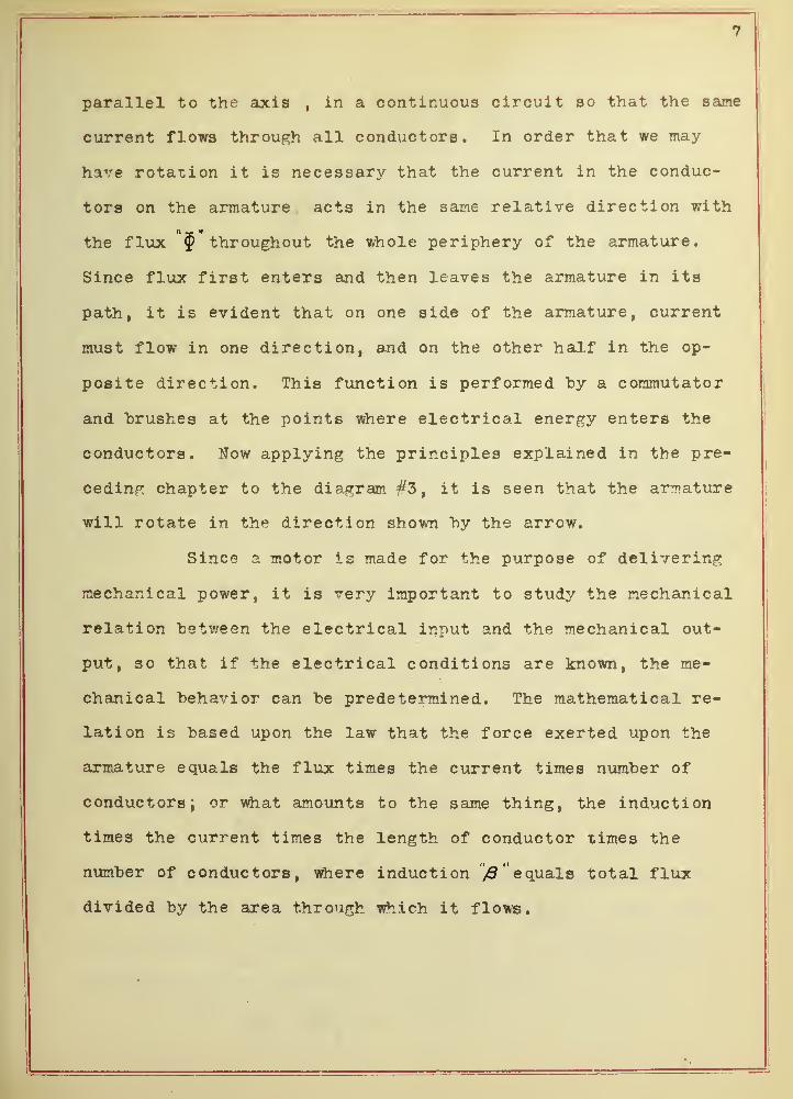
parallel to the axis , in a continuous circuit so that the same
current flows through all conductors. In order that we may-
have rotation it is necessary that the current in the conduc-
tors on the armature acts in the sane relative direction with
the flux throughout the whole periphery of the armature.
Since flux first enters and then leaves the armature in its
path, it is evident that on one side of the armature, current
must flow in one direction, and on the other half in the op-
posite direction. This function is performed by a commutator
and brushes at the points where electrical energy enters the
conductors. Now applying the principles explained in the pre-
ceding chapter to the diagram #3, it is seen that the armature
will rotate in the direction shown "by the arrow.
Since a motor is made for the purpose of delivering
mechanical power, it is very important to studjr the mechanical
relation "between the electrical input and the mechanical out-
put, so that if the electrical conditions are known, the me-
chanical behavior can be predetermined. The mathematical re-
lation is based upon the law that the force exerted upon the
armature equals the flux times the current times number of
conductors; or what amounts to the same thing, the induction
times the current times the length of conductor times the
number of conductors, where induction equals total flux
divided by the area through which it flows.

p
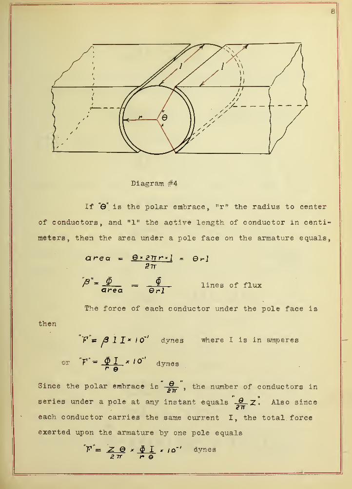
Diagram #4
If "0" is the polar embrace, Mr" the radius to center
of conductors, and "1" the active length of conductor in centi-
meters, then the area under a pole face on the armature equals,
area - Q* S7rr*l = e^JSir
area Grllines of flux
The force of each conductor under the pole face is
then
V & j3 II* 10"' dynes where I is in amperes
or "V "= $ I * 10" dynes
Since the polar embrace is -~ , the number of conductors in3 IT
'* if
series under a pole at any instant equals & ~Z . Also sinceSir
each conductor carries the same current I, the total force
exerted upon the armature by one pole equals
"V = Z 6 x $ I x 10"' dynes2 ~rr t- ©


9
or V= ^_$_L X 10''
2lr,~ dynes
This force acts at a radius of "r" centimeters, so that the
torque in dyne-centimeters equals
V"= Z$I r x iq ' m z; $1 * iq-' dvne cm.
2tt r 2 7r
For a two pole machine therefore
"T'= ^ $1 * iq-' dyne cm>
And in general for a machine with "p" pair of poles
"7"'= pz <$ I* i o'TT
.-I
dyne cm.
^26* /o a ln * f<t * starting torque
Multiplying: "by the angular velocity "w", where "w"_ PTr N60
where N equals R.P.M. , and dividing "by 550 gives power in H.P.
"V"= T 2TrN = pz $ I x 2tt n60x55O 4.26y/d« 60x5So
P = .000191 N T horse power
= .1425 N T watts
Changing N to R.P.S. and T to # inches
P = .71 NT watts
Also > pZ$I*&rN. 7+6 watts, where N= R.P.S
2 p z s a constant called z'io*


10
Equating "both values of P
l"b. inches starting torque
Kunning torque equals
T = 1.41 V rb. inchesN
The impressed electromotive force "E/ 1 opposes a
counter electromotive force "E c" generated within the motor
which equals $ Z'N and forces a current "!«, " through the
armature of resistance ,1R Q " , therefore
X" = $Z'N + I. K<
This gives directly expressions for speed and current
"N" = E^-XA
and "Jl = £ v - gZW
The power input to the armature of motor therefore equals
"EX = 0Z'NI. +
which does not include friction, windage, hysteresis, and eddy
current losses, etc.
The above are the fundamental formulae for all direct
current motors.
Since the motor consists essentially of two electri-
cal circuits and a magnetic circuit, it is evident that their


11
relation to each other can be varied with different connections;
i.e., the field circuit can be shunted across the armature cir-
cuit, or be connected in series with it, or various combina-
tions of both. This divides the direct current motor into
three distinct divisions called the shunt motor, series motor,
and the compound motor, respectively. They are all ?roverned
by the same fundamental laws, yet are widely different in their
behavior, and so will be considered under separate chapters.


12
CHAPTER II
Shunt D. C. Motor
Diagram #5
The above diagram is a simple representation of a
shunt motor. The chief characteristic of a shunt motor is
the fact that for loads within its working range, the speed
is practically constant, not falling more than a few percent.
The reason for this is as follows. As long as the field re-
sistance remains constant, and assuming that the impressed
voltage remains constant, it is evident that the field current
remains constant. Since the field turns are fixed, the mag-
netic- motive force or ampere turns remains constant, and
since the magnetic reluctance is constant, then it is evident
that by neglecting the armature reactions, that the flux can
be considered constant for all loads. Prom our speed equation
The change in speed will be due to the change in "I„ n for dif-
ferent loads, but sincewR^ is very small, the "I^R*" drop is


IT
very small.
Considering then that "N" is practically constant,
from the equation
P = .71 H T
it is evident that'P varies
directly as the torque. Also from the equation
it is evident that in a
shunt motor the torque varies directly as the current, and will
be a straight line. The limiting value of current, and there-
fore of torque, will be due to heating. It is also very plain
from the equation
that the same value of
torque can be produced by changing the relative values of $ ,
Z'' , and i' over a considerable range. This means that by in-
creasing the flux $ " and the factor Z ,1 can be decreased
and the torque "T" still remain constant, so that the specific
torque or torque per ampere is increased. This can best be
shown by considering an actual case where $ = 5*l0 6
2'' = 6 * I0~G
, and the relation between "T" and "I " is as
tabulated.
»JT» 10 25 50 75 100 125 150
wj> n 423 1058 2115 3170 4230 5300 6350
By increasing $ to I0*I06
lines, and z' to 7*/o
the following relation is obtained as tabulated.
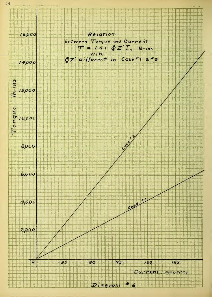
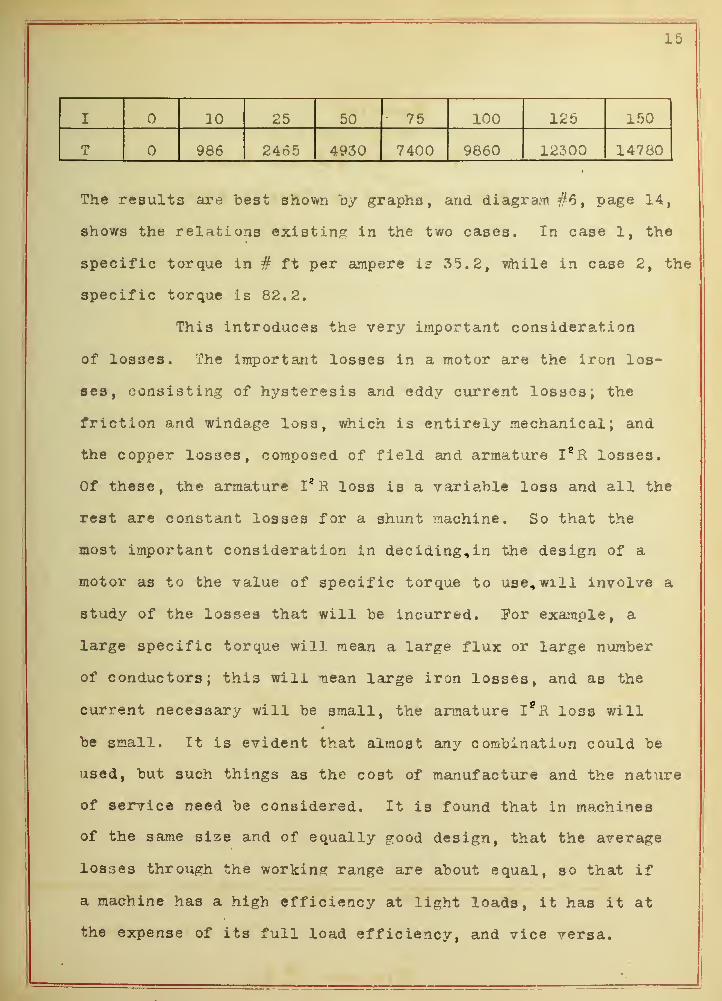
15
I 10 25 50 • 75 100 125 150
T 966 2465 4930 7400 9660 12300 14760
The results are "best shown by graphs, and diagram #6, page 14,
shows the relations existing in the two cases. In case 1, the
specific torque in # ft per ampere is 35.2, while in case 2, the
specific torque is 82.2.
This introduces the very important consideration
of losses. The important losses in a motor are the iron los-
ses, consisting of hysteresis and eddy current losses; the
friction and windage loss, which is entirely mechanical; and
the copper losses, composed of field and armature I S R losses.
Of these, the armature I* R loss is a variable loss and all the
rest are constant losses for a shunt machine. So that the
most important consideration in deciding, in the design of a
motor as to the value of specific torque to use, will involve a
study of the losses that will be incurred. For example, a
large specific torque will mean a large flux or large number
of conductors; this will mean large iron losses, and as the
current necessary will be small, the armature I*H loss will4
be small. It is evident that almost any combination could be
used, but such things as the cost of manufacture and the nature
of service need be considered. It is found that in machines
of the same size and of equally good design, that the average
losses through the working range are about equal, so that if
a machine has a high efficiency at light loads, it has it at
the expense of its full load efficiency, and vice versa.


16
The starting current will depend upon the current
necessary to "bring the machine up to normal speed under a defin-
ite load. While the machine is at rest, no counter e.m.f. is
developed, so that if "E" were impressed the current would he
limited only by "R" and would he immense; and would ruin the
machine. It is usually limited to 150^ or 200^ of normal full
load value by a starting resistance in series ?/ith the arma-
ture, which reduces the pressure across the armature. This re-
sistance is gradually cut out as the counter electromotive force
takes the place of the resistance drop.
To better consider the characteristics of a shunt
machine, take for example a 100 B.H.P. motor rated to run at
1,000 R.P.M. under full load, on a 500 volt circuit. Assume
that at full load its efficiency is 90^, and that at full load
its constant and variable losses are 60^ and A0% of total losses,
respectively. By applying the formulae derived for the direct
current motor under the assumed conditions, the following values
are obtained:


18
Percent Load 25.8 51. 75.7 100 123.3 146.
Output H.P. 25. 8 51 75.7 100 123 .
3
146
Efficiency- . 785 . 867 . 89 . 90 . 898 . 897
Input K.W. 5 . 04 C\ A A t\24. 49 i
/* *7 A A63 . 44 83
.
102. 34 121. D4
Losses { total )KW C f\ A5 . 04 5 . 25 6 . 93 D O A8. 4 10 .
3
1^ . oy
" (I R) ". 21 . 844 1.895 3 .36 5. 26 Pf CI?
7 . 55
" (Constant)KW 5.04 5.04 5.04 5.04 5. 04 5. 04 .5.04
" (field I R) . 84 .84 . 84 . 84 . 84 .84 .84
(Const. Arm) " 4.2 4.2 4.2 4,2 4.2 4.2 4.2
Input to Armature" 4 .
2
23 . 65 43 .
1
62. 6 82. 16 101 .
5
120 .
7
Ex 550 550 550 550 550 550 550
I (total) 7 .64 43 .04 78.44 113 .84 149.1 184.64 219. 64
I (light) 7.64 7.64 7.64 7. 64 7.64 7.64 7.64
I (to overcome R ) 35.4 70.8 106.2 141.46 177. 212.
R<sr
.168 .168 .168 .168 .168 .168 .168
31.4 31.4 31,4 31.4 31. 4 31.4 31. 4
$Z (effective) 30 30 30 30 30 30 30
Number of Poles 4 4 4 4 4 4 4
mm
Z 125 125 125 125 125 125 125
mm*z 5x10
-65x10 5x10
-65x10
-65x10 5x10 5x10
w 6x10*6
6x10 6x10* 6xl06
6x10 6xl06
6x10*
1.29 7.23 13. 2 19.1 25.
1
31. 36.8
Speed R.R.S. 17.45 17.27 17.08 16.9 16.66 16.5 16.3
Torque lbs.ft. 130 .
8
261 392 525 654 785


20
Plotting speed, input, output, losses, and efficiency as ordi-
nates, and percent load as abscissa, some of the characteristics
of the shunt motor are obtained as shown on diagram #7, page 17.
The starting torque of the motor under consideration
can be obtained by assuming various starting currents supplied.
The results are tabulated as follows:
Current 25 50 75 100 150 200
Starting Torque ^ft. 88.2 176.4 264.6 352.8 530 706
Ts x S„ x 2"fr j-fQ 12.5 25.1 37.6 50.2 75.3 100.4
Input .84 14.59 28.34 42.09 55.84 83.34 110.84
Torque Efficiency .857 .885 .892 .90 .904 .907
Plotting running torque from table on page 18, starting torque,
true efficiency from table on page 18, and torque efficiency
as ordinates, against current as abscissa, the relation between
running and starting torque, and the relation between true ef-
ficiency and torque efficiency axe readily seen. These charac-
teristics are shown on diagram #8, page 19.
It is seen that torque efficiency is much higher at
light loads than true efficiency, but that at full load they
are equal. It is also noted that if a value of current equal
to full load current were forced through the motor that the
running torque at full load is equal to the starting torque.
By plotting speed as ordinate, and torque as abscissa, it is
advantageous to draw in lines of constant horse power as shown
on diagram #9, page 21. From these lines, for any value of

22
horse power desired, it is possible to select any speed and the
required torque, within the limits of speed and torque. The
speed curve of the motor considered previously show3 the speed
at different power outputs.
The shunt motor has been found in this chapter to
be essentially a motor of practically constant speed, making
it desirable for driving line shafting in factories, and all
machines where a constant speed for all loads is desired. Its
speed can be changed by different methods when desired, but
that is not within the scope of this treatise. The torque
varies directly as the load and as the current, so that the
torque that a shunt motor will give is limited only by the
value of current where heating is disastrous to the machine.

23
CHAPTER III
Series D. C. Motor
Diagram #10
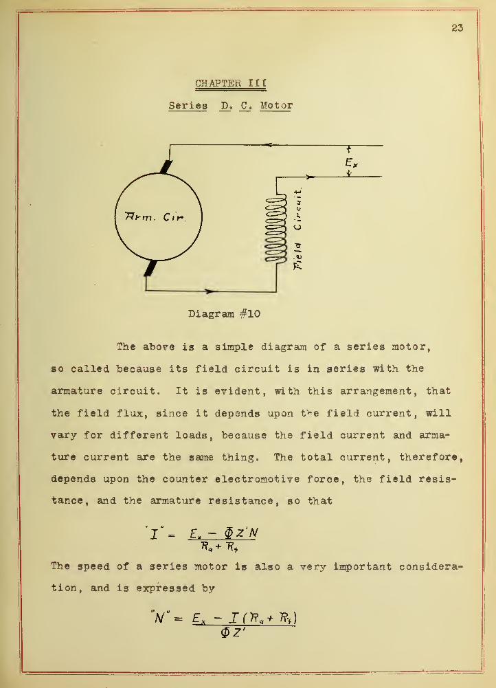
The above is a simple diagram of a series motor,
so called because its field circuit is in series with the
armature circuit. It is evident, with this arrangement, that
the field flux, since it depends upon t^e field current, will
vary for different loads, because the field current and arma-
ture current are the same thing. The total current, therefore,
depends upon the counter electromotive force, the field resis-
tance, and the armature resistance, so that
= £, - §Zjsf
The speed of a series motor is also a very important considera-
tion, and is expressed by
V- E, - ICR.* *U§2'

24-< « Cj OOV D i HD 'OD N3DZi31Q 3N39fl3 9VE ON

c
25
Theoretically §z' will be infinitely small at no load, bo that« M
the speed becomes infinitely great. As load is increased I„
it i* ti u
increases and <J)Z' increases, so that with increased load N de-
creases very rapidly. It is for this reason that a series
motor will race at light loads.
The torque equations of the direct current motors
"T"= 1.41 $Z'I9
and "T" = j±l VN
but they have a very different significance in a series motor
" x. •"
than in a shunt motor, due to the fact that <PZ increases with
I," in a manner dependent upon the saturation curve of the mag-
netic circuit. This can best be considered by taking an ex-
ample. Assume a relation between flux and current as is shown
by case #1, diagram #11, page 24; assume a value of 5 x 10 for
Z, and for various values of current "l^' the value of torque can
be calculated from
T" = I. 4/ §Z't*
as is tabulated below.

26
Case #1
40 80 120J- *J 160afcW V/ 200 240
/
5x10* 5x10* 5x10^
5xl0~* 5x10* 5x10"
*
5x10⁶
1.85x103.62x104.92x10* 5.63x10* 5 . 91x10 6x10*
9.25 18.2 24.6 28.15 29.6 30
T 522 2050 4170 6400 83 50 10150
lbs/amp. ) 1,085 2.14 2.89 3.33 3.47 3.52
The effect of changing the relation between §z' and
I," may be shown by considering another example, assuming a re-
lation between current and flux as shown on diagram #11, page
24, as case #2. Results are as follows:
Current 40 80 120 160 200 240
Z'«6
5x10 5x10"6
5x10"6
5xl0"6
5x10"* 5x10* 5x10"
§ 2.45x10* 4 . 8x10* 6.38x10* 7.1 5x10* 7 . 4x10* 7.5x10'
12.25 24 31.9 35.7 37. 37.5
"T" 692 2710 5400 8060 10450 12700
ft . lbs/amp 1.41 2.82 3.75 4.19 4.35 4.4
A study of the results and curves shows that an in-
crease of flux with current brings an increase of specific
t or que
.
The chief characteristic of a series motor is the
fact that at large loads it has a large starting torque. This
is due to the fact that at large loads the current is

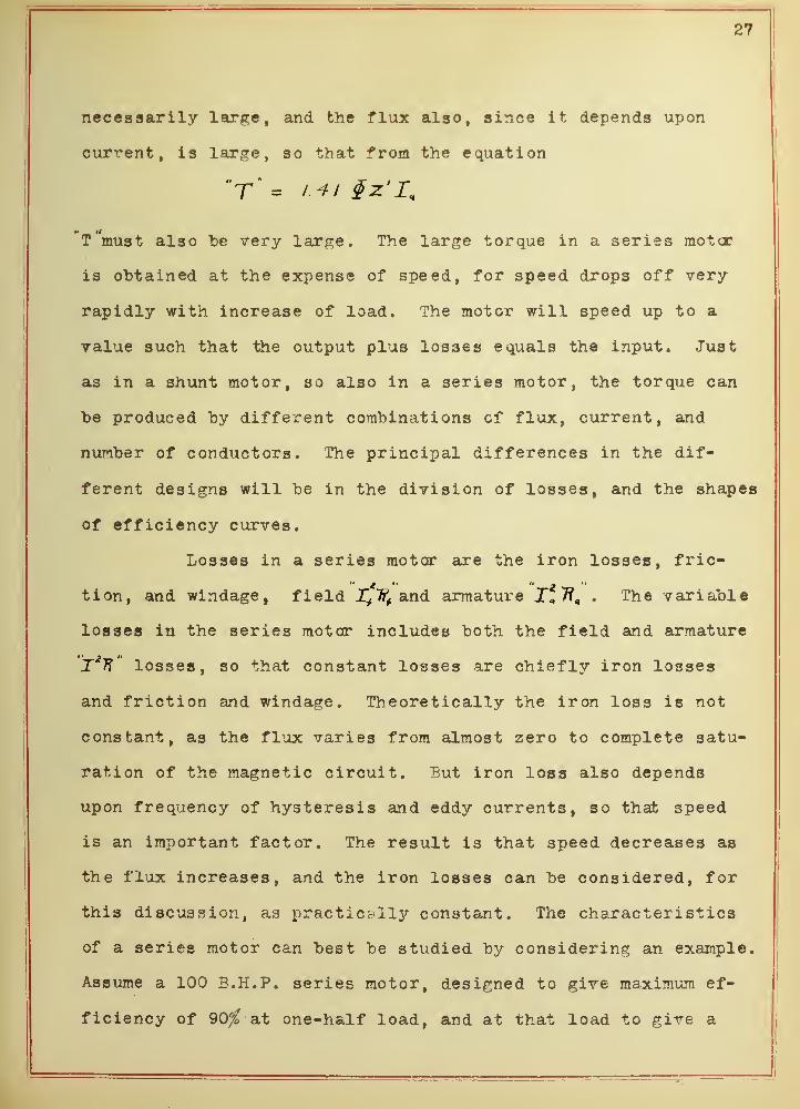
27
necessarily large, and the flux also, since it depends upon
current, is large, so that from the equation
T'must also "be very large. The large torque in a series motor
is obtained at the expense of speed, for speed drops off very
rapidly with increase of load. The motor will speed up to a
value such that the output plus losses equals the input. Just
as in a shunt motor, so also in a series motor, the torque can
be produced by different combinations of flux, current, and
number of conductors. The principal differences in the dif-
ferent designs will be in the division of losses, and the shapes
of efficiency curves.
Losses in a series motor are the iron losses, fric-
tion, and windage, field 1+% and armature X„ 7?, . The variable
losses in the series motor includes both the field and armature
jT'TF' losses, so that constant losses are chiefly iron losses
and friction and windage. Theoretically the iron loss is not
constant, as the flux varies from almost zero to complete satu-
ration of the magnetic circuit. But iron loss also depends
upon frequency of hysteresis and eddy currents, so that speed
is an important factor. The result is that speed decreases as
the flux increases, and the iron losses can be considered, for
this discussion, as practically constant. The characteristics
of a series motor can best be studied by considering an example.
Assume a 100 B.H.P. series motor, designed to give maximum ef-
ficiency of 90% at one-half load, and at that load to give a
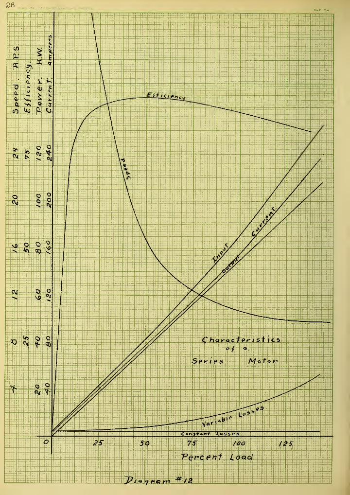
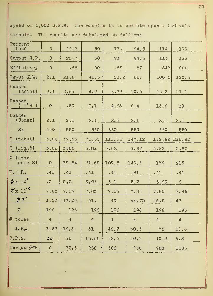
29
speed of 1,000 R.P.M. The machine is to operate upon a 550 volt
circuit. The results are tabulated as follows:
PercentLoad 25.7 50 73. 94.5 114 133
Output H.P. 25.7 50 73 94. 5 114 133
-Ciii i c i ency u D D• OO Q Q q r>
. o f . o4 rQ O OOde.
Input K.W. 2.1 21.8 41. 5 61.2 81. 100.5 120. 5
Losses< . 1 C. DO 4 . d, • ! C;
T A PL1U •T R 1 £1.1
X. cs cooJ_/US DCS( I
2 H ) . 53 2.1 4.63 8.4 13.2 19
Losses(Const) 2.1 2.1 2.1 2.1 2.1 2.1 2.1
Ex 550 550 550 550 550 550 550
I (total) 3.82 39.66 75. 50 111.32 147.12 182.82 218.82
I (light) 3.82 3.82 3.82 3.82 3.82 3.82 3.82
I ( over-come R) 3 5 . 84 71. 68 107. 5 143 .
3
179 215
"R -i, P AT• 4 J. . • 41 . 4± A 1
. 41 • 41 A T. 41
o o <z at; R T R 7. I R QTt /?
O
f • O O 7 PR 7 PR 7 PR 7 OR 7 ORr • c D
JET *» 1 57 17 ?5 uii A A 7 K d £ R A7ft r
z 196 196 196 196 196 196 196
# poles 4 4 4 4 4 4 4
I « R 4+< 1.57 16.3 31 45.7 60.5 75 89.6
R.P.S. oc 31 16.66 12.6 10.9 10.2 9.8
Torque #ft 72.5.
252 506 760 980 1185


31
Plotting speed, efficiency, input, output, current,
and losses as ordinates, against percent load as abscissa,
some of the characteristics of the series motor are obtained.
They are shown on diagram #12, page 28.
The starting torque of the series motor under con-
sideration can he obtained for different values of current
forced through the machine, since the relation between flux
set up and current is known from the above tabulation. The
values of starting torque are therefore calculated and tabu-
lated as follows:
Current 40 80 120 160 200 240
Flux f 2.2x10* 4.13x10* 5.3x10* 5 . 8x10* 5. 9 5x16
* 6x10*
Z' 7.85x10 7.85x10 7 . 85x10 7.85x10 7.85x10 7.85x16' 7.85x10
$z' 17.25 32.4 41.6 45.5 46.7 47.
Startingtorque #ft 81.2 296 587 857 1100 1325
SpeedR.P.S. cc 31 16.2 12 10.6 10 9.8
21.5 41 60 77.6 94 111
Input 22. 44 66 88 110 132
Torque Ef-ficiency .978 .932 .91 .882 .854 .84
Plotting flux, starting torque, running torque, true
efficiency, and torque efficiency, as ordinates, against cur-
rent as abscissa, the relation between starting and running
torque, and the relation between true efficiency and torque


32
efficiency are readily seen. Refer to diagram #13 ,page 30.
The fact that the series motor can exert such a large
starting torque on heavy loads makes it of great importance on
such classes of service where large starting torques are re-
quired, and speed regulation is not important. For this
reason, the series motor is used on railway cars and cranes and
that class of service. Series motors are rated at the maximum
torque they will exert, but can not be operated on more than
half load continuously, as heating would be disastrous to the
machine
.

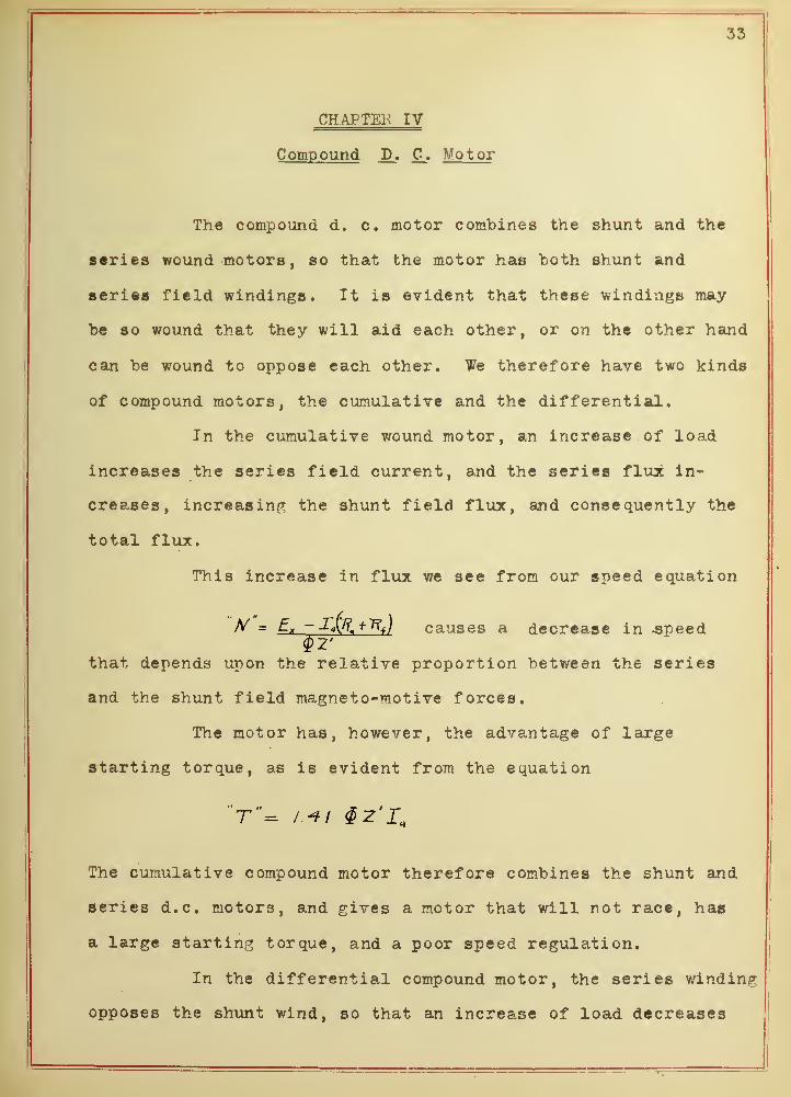
33
CHAPTEK IV
Compound D. C_. Motor
The compound d. c. motor combines the shunt and the
series wound motors, so that the motor has both shunt and
series field windings. It is evident that these windings may
be so wound that they will aid each other, or on the other hand
can be wound to oppose each other. We therefore have two kinds
of compound motors, the cumulative and the differential.
In the cumulative wound motor, an increase of load
increases the series field current, and the series flux in-
creases, increasing the shunt field flux, and consequently the
total flux.
This increase in flux we see from our speed equation
N = Ex -j^SLjlSJ causes a decrease in -speed
that depends upon the relative proportion between the series
and the shunt field magneto-motive forces.
The motor has, however, the advantage of large
starting torque, as is evident from the equation
"T"= /.-*/ gz'r.
The cumulative compound motor therefore combines the shunt and
series d.c. motors, and gives a motor that will not race, has
a large starting torque, and a poor speed regulation.
In the differential compound motor, the series winding
opposes the shunt wind, so that an increase of load decreases
34
the flux and the motor speeds up. The starting torque is de-
creased. These changes are proportional to the series and
hunt magneto-motive forces. The differential compound motor
is usually designed to give perfect speed regulation, so that
the amount of series flux opposing the shunt flux is just
enough to keep the motor speed constant.

35
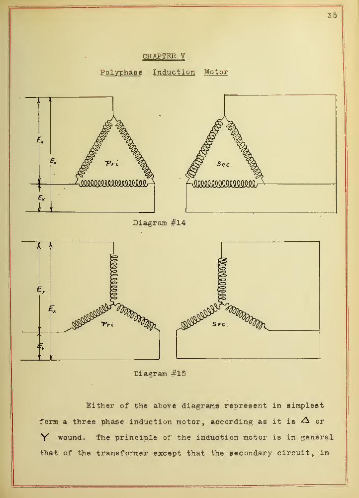
CHAPTEH V
Polyphase Induction Motor
i_J I I
Diagram #14
i t
Diagram #15
Either of the above diagrams represent in simplest
form a three phase induction motor, according as it is ^ or
V wound. The principle of the induction motor is in general
that of the transformer except that the secondary circuit, in

36

37
the case of the induction motor, is free to rotate about an
axis. If the induction motor were "blocked, it could be used
as a transformer. There are in general two types of induction
motors: the squirrel cage, and the wound rotor. The differ-
ence in them is that in the squirrel cage motor the secondary
conductors are copper bars in armature slots, all connected
electrically to a copper ring on each end of the armature,
while the wound rotor has the ordinary windings. The nature
of the primary winding in both, and the secondary of the wound
rotor, is the same as is found in a polyphase alternator.
A3 was before stated, the principle of the induction
motor is that of the transformer, except that the secondary
is free to rotate. The magnetic path is still present in the
motor, for the flux is forced across an air gap that is made
as small as possible. The flux, in streaming across the air
gap, cuts across the conductors of the rotor; an electromotive
force is induced in them that forces a current through the
conductors that is limited by the value of resistance in the
secondary. This induced current sets up a flux about the con-
ductors, and a torque is produced, as explained in the intro-
duction, and the rotor revolves. The main flux, which is set
up by the primary, is in a state of rotation, so that it really
tends to drag the rotor conductors around at as near the same
speed as possible.
The fact that the main flux rotates may be shown as
follows. In diagram #16, page 36, curves A, B, and C represent

38 Y
Y'
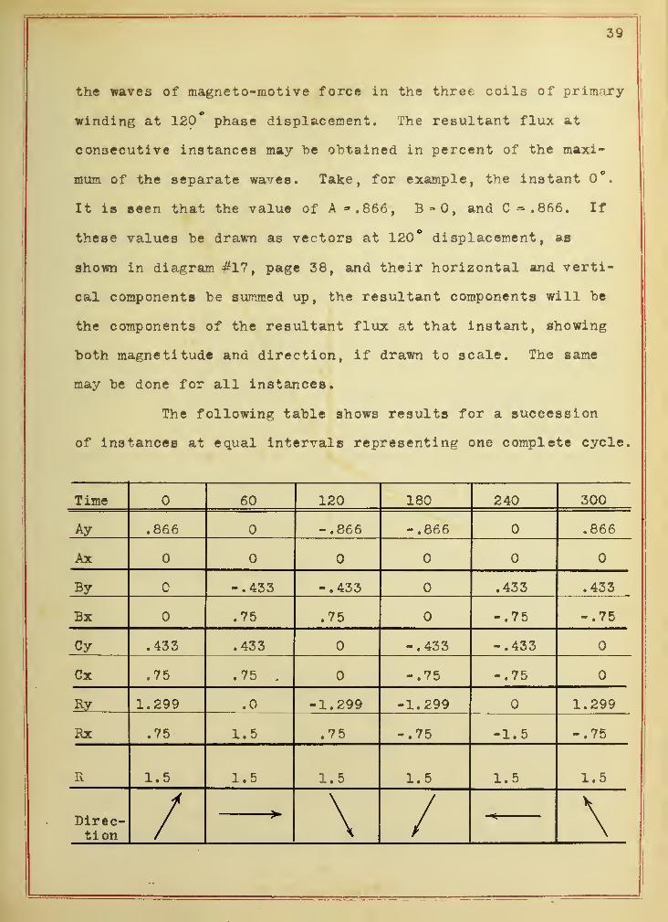
39
the waves of magneto-motive force in the three coils of primary-
winding at 120* phase displacement. The resultant flux at
consecutive instances may he obtained in percent of the maxi-
mum of the separate waves. Take, for example, the instant 0°.
It is seen that the value of A - . 866 , B = 0, and C=.866. If
these values be drawn as vectors at 120° displacement, as
shown in diagram #17, page 38, and their horizontal and verti-
cal components be summed up, the resultant components will be
the components of the resultant flux at that instant, showing
both magnetitude and direction, if drawn to scale. The same
may be done for all instances.
The following table shows results for a succession
of instances at equal intervals representing one complete cycle.
Time 60 120 180 240 300
Ay .866 -.866 -.866 .866
Ax
By c -.433 -.433 .433 .433
Bx .75 .75 -.75 -.75
Cy .433 .433 -.433 -.433
Cx .75 .75 . -.75 -.75
Ry 1.299 .0 -1.299 -1.299 1.299
Rx .75 1.5 .75 -.75 -1.5 -.75
R 1.5 1.5 1.5 1.5 1. 5 1.5
>» /Direc-tion / \ —S: \
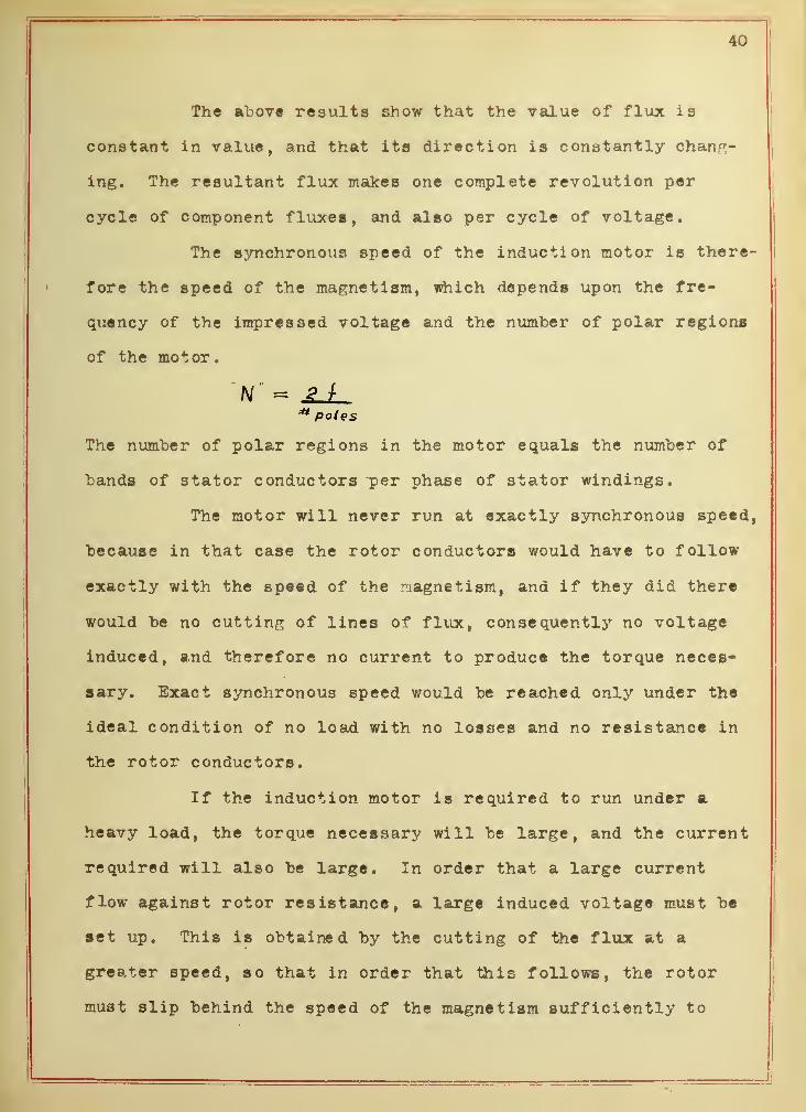
40
The above results show that the value of flux is
constant in value, and that its direction is constantly chang-
ing. The resultant flux makes one complete revolution per
cycle of component fluxes, and also per cycle of voltage.
The synchronous speed of the induction motor is there-
fore the speed of the magnetism, which depends upon the fre-
quency of the impressed voltage and the number of polar regions
of the motor.
N « .£_£_poles
The number of polar regions in the motor equals the number of
bands of stator conductors "per phase of stator windings.
The motor will never run at exactly synchronous speed,
because in that case the rotor conductors would have to follow
exactly with the speed of the magnetism, and if they did there
would be no cutting of lines of flux, consequently no voltage
induced, and therefore no current to produce the torque neces-
sary. Exact synchronous speed would be reached onljr under the
ideal condition of no load with no losses and no resistance in
the rotor conductors.
If the induction motor is required to run under a
heavy load, the torque necessary will be large, and the current
required will also be large. In order that a large current
flow against rotor resistance, a large induced voltage must be
set up. This is obtained by the cutting of the flux at a
greater speed, so that in order that this follows, the rotor
must slip behind the speed of the magnetism sufficiently to

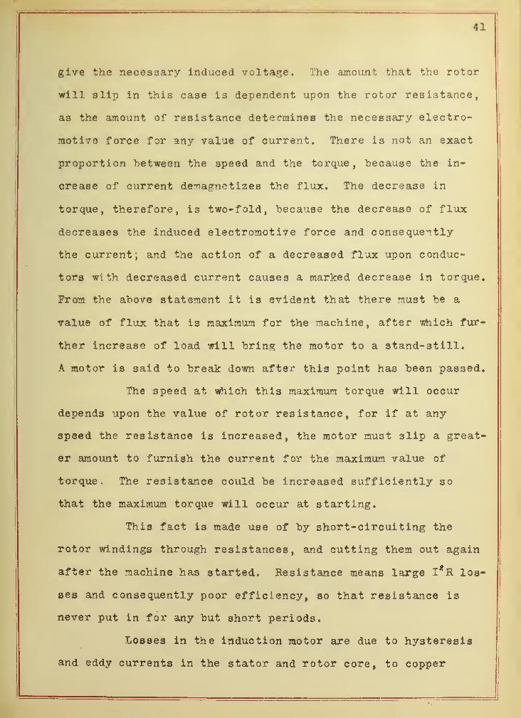
41
give the necessary induced voltage. The amount that the rotor
will slip in this case is dependent upon the rotor resistance,
as the amount of resistance determines the necessary electro-
motive force for any value of current. There is not an exact
proportion "between the speed and the torque, because the in-
crease of current demagnetizes the flux. The decrease in
torque, therefore, is two-fold, "because the decrease of flux
decreases the induced electromotive force and consequently
the current; and the action of a decreased flux upon conduc-
tors with decreased current causes a marked decrease in torque.
From the ahove statement it is evident that there must be a
value of flux that is maximum for the machine, after which fur-
ther increase of load will bring the motor to a stand-still.
A motor is said to break down after this point has been passed.
The speed at which this maximum torque will occur
depends upon the value of rotor resistance, for if at any
speed the resistance is increased, the motor must slip a great-
er amount to furnish the current for the maximum value of
torque. The resistance could be increased sufficiently so
that the maximum torque will occur at starting.
This fact is made use of by short-circuiting the
rotor windings through resistances, and cutting them out again
after the machine has started. Resistance means large Is R los-
ses and consequently poor efficiency, so that resistance is
never put in for any but short periods.
Losses in the induction motor are due to hysteresis
and eddy currents in the stator and rotor core, to copper
1 —42
losses in the windings, and to the friction and windage of the
rotor.
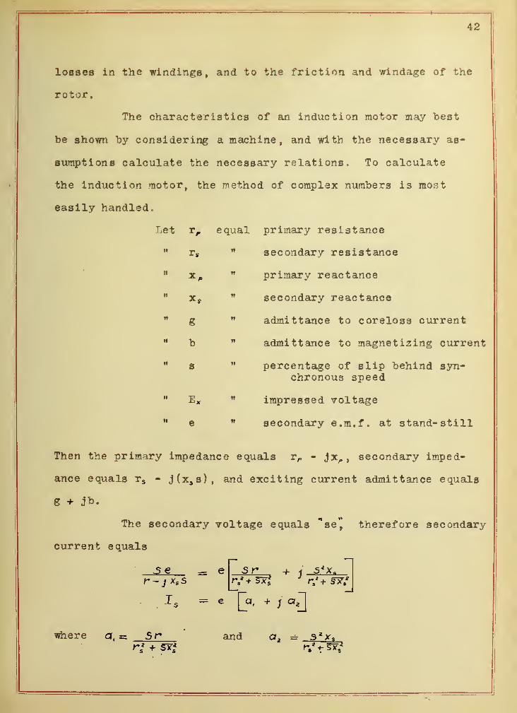
The characteristics of an induction motor may best
he shown "by considering a machine, and with the necessary as-
sumptions calculate the necessary relations. To calculate
the induction motor, the method of complex numbers is most
easily handled.
Let tp equal primary resistance
" ts" secondary resistance
" x„ M primary reactance
Xj " secondary reactance
" g " admittance to coreloss current
" b 11 admittance to magnetizing current
" s " percentage of slip behind syn-chronous speed
" Ex " impressed voltage
e secondary e.m.f . at stand- still
Then the primary impedance equals rP - Jx,, ,secondary imped-
ance equals rs - j(xs s), and exciting current admittance equals
g + jt>.
The secondary voltage equals *se" therefore secondary
current equals
5 r + j s*x*
[a, + ; af[
>S e = e
s
where a, =s Sr and az= s**?


43
The exciting current equals
I?* - e(q + 4 b)9 +1
Therefore primary current equals
J P = e[(a, + 9) + j(q z + b)]
" 1" "
/"
where b, ~ a, + cj. and fc2 3
Ex"a e+Ip2p = e + e J(Vy -/*,.)
= e ( c, + ; cJ
where "c," = (1 + b, rP + bs *J *cj = (yz rP - k x P)
and
The watts supplied to the motor by I P and"E x
equals P' = e*(b,c, -t fc,c8 )
The volt amperes supplied equals "lP E x
"
Power factor = e*(b, c, + b*c t )
The torque in the secondary in synchronous watts
equals "T synl = Q, where "T syn" would he
power in watts if motor ran at syn. speed.
Transforming to lhs.ft.
"tJ = STtNT x 746S50
hut N = _2±* poles


44
T "Stir V46
lha'
ft'per phase
~ 1,7 ^~sv lbs. ft. per phase
Mechanical P = T^x Speed
or equals 2tt T N jj psso
where T * lbs. ft. and JT = R.K.S.
Therefore efficiency = ' "P w<. c /, - |*jctu>ige*(b.c, +ba c a )
Consider as an example an induction motor, rated at 5 H.P. at
900 R.P.M. , on a 110 volt circuit, at 60 »v. Assume that the
machine is an. 8 pole machine -A wound; that
rs = .25 ohms x s = 1.00 ohms b == .058
r„ ~ .20 " x„ = 1.2 g = .0073
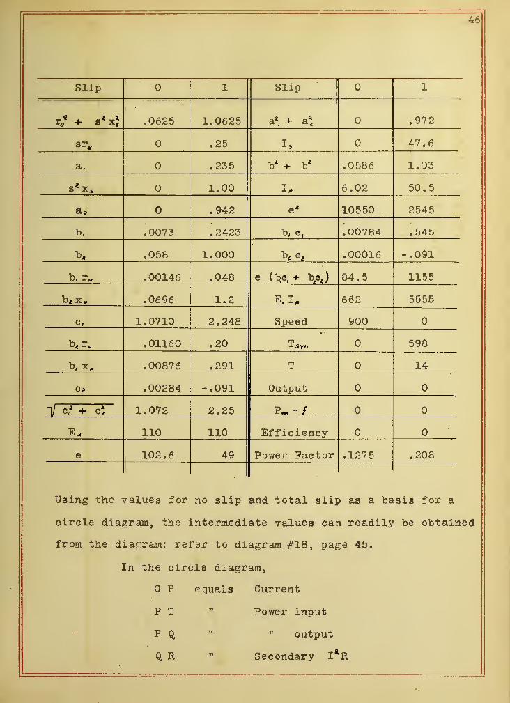
The necessary values can "be found by complex quanti-
ties for no slip and total slip as tabulated below, and other
intermediate values taken from a circle diagram. The results
are as follows.

46
Slip 1 Slip 1
r/ + x| .0625 1.0625 a2, + a* .972
.25 Is 47.6
a, .235 b* + b* .0586 1.03
S* X s 1.00 I, 6.02 50.5
.942 c 4 10550 2545
b. .0073 .2423 b, e, .00784 .545
t>* .058 1.000 b2 cz .00016 -.091
b, r„ .00146 .048 e (b.e, + b/sj 84. 5 1155
b* x„ .0696 1.2 Kip 662 5555
c, 1.0710 2.248 Speed 900
r„ .01160 .20 598
I), .00876 .291 T 14
c* .00284 -.091 Output
1/ c* -+- c\ 1.072 2.25
E x 110 110 Efficiency-
e 102.6 49 Power Factor .1275 .208
Using the values for no slip and total slip as a basis for a
circle diagram, the intermediate values can readily be obtained
from the diagram: refer to diagram #18, page 45.
In the circle diagram,
P equals Current
P T M Power input
P Q » output
Q R " Secondary I*R

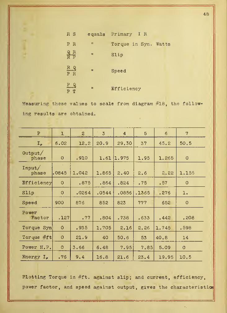
48
Primary I R
Torque in Syn. Watts
Slip
Speed
Efficiency
"Measuring these values to scale from diagram #18, the follow-
ing results are obtained.
p i pa O t R D 7
I P 6.02 12.2 20.9 29.30 37 45.2 50.5
Output/phase .910 1.61 1.975 1.95 1.265
Input/phase .0845 1.042 1.865 2.40 2.6 2.22 1.155
Efficiency .875 .864 .824 .75 .57
Slip .0264 .0544 .0856 .1365 .276 1.
Speed 900 876 852 823 777 652
PowerPact or .127 .77 .804 .738 .633 .442 .208
Torque Syn .93 5 1.705 2.16 2.26 1.745 .598
Torque #ft 21.9 40 50.6 53 40.8 14
Power H.P. 3.66 6.48 7.95 7.85 5.09
Energy I p .76 9.4 16.8 21.6 23.4 19.95 10.5
Plotting Torque in #ft. against slip; and current, efficiency,
power factor, and speed against output, gives the characteristics
R S
P R
1*R P
P R
P_£
P T
e quals


49
of the induction motor considered. Refer to diagram #19, page
47.
The starting torque of an induction motor depends
upon the current flowing in the secondary windings, the flux,
and the number of rotor conductors. The current in the secon-
dary depends upon the resistance of the conductors, and the
induced voltage.
It can he proven that "by increasing the resistance
of the rotor circuit, the maximum torque will occur at a
greater slip and the torque at total slip will increase, so
that it is evident that there will he a value of resistance
such that the maximum torque will occur at starting. This
value of resistance is found to be a value equal to the rest
of the impedance of the machine. The values of starting torque
can be found for the same machine by increasing the secondary
resistance, and the relation between current and starting
torque determined. The results are as follows.


50
.1 .25 .50 .75 1.
a
,
.099 .23 5 .40 .48 . 5
a* .99 .942 .80 . 64 . 5
b, .1063 .2423 .4073 . 4873 .5073
b< 1.048 1.000 .858 .698 . 558
c, 2.279 2.25 2.11 1.94 1.77
c* .082 -.091 -.3164 - .4454 - . 50
110 110 110 110 110
e 48.25 49 51.6 55.3 59.8
Is 48.25 47.6 46.1 44.25 42.25
50.9 50.5 49. 47 45
e* 2330 2545 2660 3060 3 580
e ( t>, c, + t3 q
)
765 1155 1565 1940 2220
5600 5555 5400 5170 4950
T.Sy/, 231 598 1063 1470 1790
T 5.4 14 24.9 34.4 42
P. P. .1365 .208 .29 .376 .448
X3(energy) 6.6 9.9 13.4 16.6 18.9

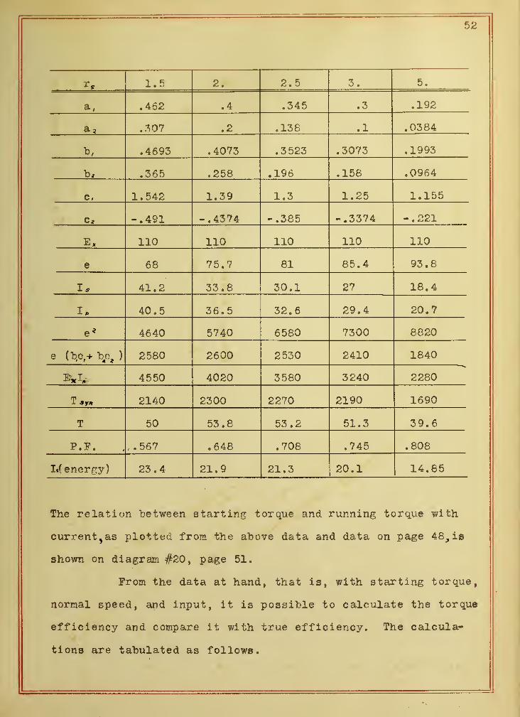
52
1.5 2. 2.5 3. 5.
a, .462 .4 .345 .3 .192
a 2 .307 .2 .138 .1 .0384
b, .4693 .4073 .3 523 .3073 .1993
b, .365 .258 .196 .158 .0964
c, 1.542 1.39 1.3 1.25 1.155
c* -.491 -.4374 -.385 -.3374 -.221
E x 110 110 110 110 110
e 68 75.7 81 85.4 93.8
Is 41.2 33.8 30.1 27 18.4
40.5 36. 5 32.6 29.4 20.7
e< 4640 5740 6580 7300 8820
e (bo,+ \o9 ) 2580 2600 2530 2410 1840
4550 4020 3580 3240 2280
2140 2300 2270 2190 1690
T 50 53.8 53.2 51.3 39.6
P.F. .567 .648 .708 .745 .808
I*( energy) 23.4 21.9 21.3 20.1 14.85
The relation between starting torque and running torque with
current>as plotted from the above data and data on page 48, is
shown on diagram #20, page 51.
Prom the data at hand, that is, with starting torque,
normal speed, and input, it is possible to calculate the torque
efficiency and compare it with true efficiency. The calcula-
tions are tabulated as follows.


54
s„ ?s* 1,1 cos e Torque Eff
22.5 15 2.87 3.174 .904 8.9
39.6 15 5.07 5. 55 .913 14.85
51.3 15 6.58 7.25 . 908 20.1
53.2 15 6.83 7.62 .897 21.3
53.8 15 6.9 7.8 .884 21.9
50 15 6.4 7.73 .83 23.4
42 15 5.38 6.66 .806 18.9
34.4 15 4.41 5.83 .756 16.6
24.9 15 3,19 4.70 .658 13.4
14 15 1.795 3.47 .518 9.9
5.4 15 .692 2.13 .325 6.6
Plotting torque efficiency, apparent efficiency,
and true efficiency against current as shown on diagram #21,
page 53, the relation between them is readily seen.
The torque characteristics and its speed character-
istic show that the induction motor is applicable to service
of a similar nature to that of the shunt d. c. motor. The in
duction motor has almost constant speed through the working
range of the machine. The speed can he varied to any desired
value but at the expense of the efficiency of operation.
The advantageousness of the induction motor is, that it is
used on alternating current circuits, and the transmission of
alternating current is always more economical than direct
current
.

T5TT


57
SUMMARY
By plotting the speed and torque curves to the same
scale as shown "by diagram #22, page 55, it is possible to com-
pare the three types of motors considered, in regard to those
characteristics. It is seen that the torque of the series motor
increases much more rapidly for a given amount of current, ex-
cept for very small values, than does the shunt or induction
motor; while a study of its speed curve shows a rapid falling
off as torque increases. The speed gradually comes to an al-
most constant value after the magnetic field becomes saturated.
After this point is reached, the motor would tend to run simi-
larly to a shunt motor, hut it occurs beyond the working range
of the machine. The torque characteristics of the shunt and
induction motors are in general similar, and their speed curves
are practically the same, so that in general they could be used
on the same class of service. But there are a good many other
considerations that determine the choice of one or the other
that do not come within the scope of this thesis, such as vari-
ous methods of speed variations, etc.
The starting torque curves as shown on diagram #23,
page 56, show the same differences as did the running torques
of the same machines.
Prom the efficiency curves as shown under each chapter,
it was seen that the torque efficiency is in all cases higher
than the true efficiency. True efficiency is based upon running
torque and speed for its output, while torque efficiency is


58
"based upon starting torque and speed. Since starting torque is
in general higher for any value of current than running torque,
the torque efficiency therefore must he higher.
The practical application of these types of motors
depends upon their torque and speed relations. The shunt motor,
due to its constant speed, is used for such service as driving
shafting or individual machines in manufacturing establishments
where constant speed is required. The induction motor is also
coming into this class of service, hut its chief advantage is
due to the fact that the induction motor operates on alternating
current, which is more economically transmitted any distance to
a factory than is the direct current, The series motor is used
in all classes of service where torque rather than speed is of
importance. This class of service is found in cranes and elec-
tric railway cars. It is essential that the load be rigidly
attached to the series motor, for on light loads the series
motor will race.


f


