David Rollinson, Kalyan Vasudev Alwala, Nico Zevallos and Howie Choset
Abstract— We present three methods of achieving compliantmotion with a snake robot by controlling the torques exerted bythe joints of the robot. Two strategies command joint torquesbased solely on the robot’s local curvature (i.e. joint angles). Athird strategy commands joint angles, velocities, and torquesbased on the recorded feedback from the robot while executinga previously defined motion under position control. The threecontrol strategies are implemented and compared on a snakerobot that includes series elastic actuation (SEA) and torquesensing at each joint, and demonstrate compliant locomotionthat adapts automatically to the robot’s surrounding terrain.
I. INTRODUCTION
Snake robots, sometimes referred to as hyper-redundantmechanisms [1], consist of actuated links chained togetherin series. A snake robot’s many degrees of freedom give itthe potential to navigate a wide range of environments byactively changing its overall shape. However, this same traitmakes snake robots difficult to control. Strategies to simplifytheir control include undulating the robot’s joint anglesaccording to parameterized sine waves [2], [3], follow-the-leader controllers [4], and central pattern generators [5].
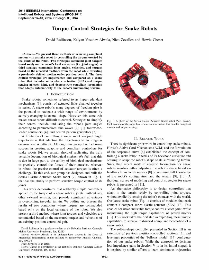
A limitation of controlling a snake robot via joint angletrajectories is that adapting the trajectories to an irregularenvironment is difficult. Although our group has had somesuccess in creating adaptive and compliant controllers forsnake robots [6], we remain short of replicating the trulyversatile locomotion of biological snakes. We feel that thisis due in large part to the ability of biological mechanismsto precisely control the forces of their muscles, whereasin robots the precise control of actuator torques is often achallenge. To this end, our group has designed and built theSeries Elastic Actuated Snake robot [7], shown in Fig. 1,that has the ability to perform sensitive torque control of itsjoints.
This work demonstrates that relatively simple controllersapplied to the torque of a snake robot’s joints, without anyother external sensing, can provide significant advantagesin overcoming irregular terrain. We outline and present theresults of two controllers where torques are commandedbased only on the local curvature of the robot. We alsopresent a third method where joint torques and velocities arecommanded based on the measured torques and velocities ofan existing position-controlled gait.
David Rollinson is a graduate student at the Robotics Institute, CarnegieMellon University, Pittsburgh, PA, 15213
Kalyan Vasudev Alwala is an undergraduate student in the Dept. ofMechanical Engineering, Indian Institute of Technology Madras, Chennai,TN, 600036
Nico Zevallos is an artist.Howie Choset is a professor at the Robotics Institute, Carnegie Mellon
University, Pittsburgh, PA, 15213
Fig. 1: A photo of the Series Elastic Actuated Snake robot (SEA Snake).Each module of the robot has series elastic actuation that enables compliantmotion and torque sensing.
II. RELATED WORK
There is significant prior work in controlling snake robots.Hirose’s Active Cord Mechanism (ACM) and the formulationof the serpenoid curve [4] established the concept of con-trolling a snake robot in terms of its backbone curvature andseeking to adapt the robot’s shape to its surrounding terrain.Since then recent work in adaptive locomotion for snakerobots involves either adjusting the robot’s shape based onfeedback from tactile sensors [8] or assuming full knowledgeof the robot’s configuration and the terrain [9], [10]. Athorough survey of modeling and control strategies for snakerobots is presented in [11].
An alternative philosophy is to design controllers thatadapt to the terrain solely by controlling joint torques,without explicitly sensing the robot’s contacts with the world.Our latest snake robot (Fig. 1) consists of modules that eachcontain a compact series elastic actuator (SEA) [12]. Thisenables sensitive and stable torque control at each joint, whilemaintaining the high torque capabilities of geared motors[13]. This work takes the first step in exploiting these uniquecapabilities to achieve real-world compliant locomotion of asnake robot.
The roll-in-shape controller presented in Section III is anextension of previous position-controlled motions [3], andleverages properties of the ‘bellows model’ [14] configura-tion of our snake robots. While the approach to derivinglow-impedance gaits in Section V is in its initial stages, itis inspired by similar efforts to learn continuous trajectories
2014 IEEE/RSJ International Conference onIntelligent Robots and Systems (IROS 2014)September 14-18, 2014, Chicago, IL, USA
Fig. 2: A visual representation of the roll-in-shape controller. The com-manded torque τ is commanded based on the local curvature κ. Thecommanded torque of the joint is the x or y component of total torque,depending on how the joint is oriented in the robot.
from demonstration for humans and humanoid robotics [15],[16]. The low-impedance sliding controller in Section IVbuilds on the work of Date et al. [17] and others [18], whodemonstrate that a simple torque law based on the derivativeof the robot’s backbone curvature can propel a wheeled snakeover obstacles and through corridors. Kamegawa et al. [19]further extended this approach in simulation for a robot withtorque controlled joints and tactile sensing.
III. COMPLIANT ROLL-IN-SHAPE
Perhaps the simplest torque-based behavior is one thatallows the robot to roll compliantly over the terrain. Theability to roll around the backbone without changing theoverall shape is a property of having joints oriented in thelateral and dorsal planes of the robot. Yamada and Hirosediscuss this configuration in detail in [14] and refer to thecorresponding convention of lateral and dorsal curvatures asa bellows model. In particular, they note the relationshipbetween the lateral and dorsal curvatures of the robot κxand κy and the Frenet-Serret curvature κ to be
κ2 = κ2x + κ2y. (1)
Intuitively, equation (1) represents how the total localcurvature of the of the robot is expressed in terms of itslocal lateral and dorsal curvatures. If we want to increaseor decrease the curvature, the ideal torque to commandwould be aligned with the curvature. However, if we wantto rotate the curvature around the backbone, while changingthe curvature as little as possible, the ideal torque commandwould be orthogonal to the curvature, as visually illustratedin Fig. 2.
As a control law, this results in torques that are a π2 rotation
from the curvature,
τx(s) = −νκy(s)τy(s) = νκx(s).
(2)
In (2), s is the position along the robot’s backbone, and νis a scaling parameter that linearly maps curvature to torqueand serves as the torque gain of the controller. The sign of νcan be used to control whether the robot twists clockwise or
Fig. 3: Diagram of the axes of the snake robot, showing alignment of therobot’s joints with the lateral and dorsal planes. The solid and dashed axesindicate actual joints of the robot.
counterclockwise around its backbone shape. For our initialwork we hand-tuned this parameter, and used a value of ν =1.0 in the results presented in Section VI-A.
If the robot’s joints are evenly spaced along the backbone,this controller can be equivalently written in terms of jointangles, with the parameter ν now scaling between jointangles and torques,
τx(s) = −νθy(s)τy(s) = νθx(s).
(3)
On our snake robots, joints are alternately oriented in thelateral and dorsal planes of the robot, as illustrated in Fig. 3.Because of this, at a given joint we have either a measuredθx or θy , but not both. Since the control law (3) requiresknowledge of the joint angle orthogonal to the joint thatis being torque-controlled, we linearly interpolate the anglebased on the angles of adjacent joints. This interpolationalso has the effect of smoothing out the robot’s measuredcurvature.
IV. EMPIRICAL GAIT CONSTRUCTION
It could be argued that the reason our snake robots moveacross the ground when executing a gait is less of a resultof its shape changes and more of a result of its torques thatare applied to cause those shape changes. Since position-controlled gaits are cyclic, when designing them we tend toexploit geometric regularity of the terrain, like flat groundand cylindrical pipes. However with torque-controlled gaitsit may be possible that a similar force-based regularity existsthat can be exploited for gait design.
Our group, as well as others, have developed a wide rangeof position-controlled gaits and motions [2], [3] that areuseful in the field. While we have had some success inmaking these gaits adapt to the robot’s environment [6], ingeneral the tuning and control of various gaits for a widerange environments is difficult. Therefore, we are interestedin methods that could endow our existing library of motionswith the low-impedance characteristics that might be enabledby torque control, without starting gait development overfrom scratch.
To generate low-impedance versions of our existing gaits,we can execute a normal position-controlled gait on the SEASnake and record the robot’s feedback, including joint angles,velocities, and torques. By executing the gait on the nominal
1094
terrain for which the gait was designed (e.g. level ground),we hope to find cyclic velocities and torques that correspondto ‘nominal’ locomotion. By playing back these positions,velocities, and torques as reference trajectories, and closingthe loop primarily on the torques and velocities, we shouldexpect to get a gait that closely mimics the original position-controlled gait on the original terrain and at the same timeis more compliant to variations and obstacles.
V. LOW-IMPEDANCE SLIDING
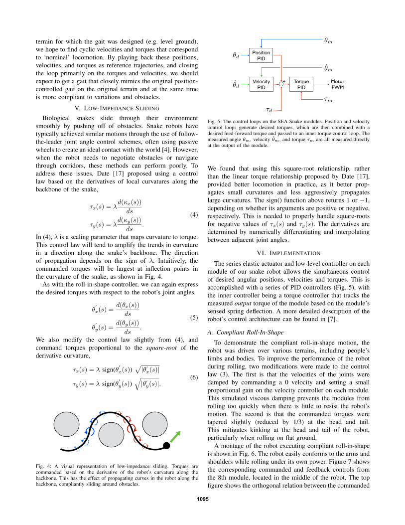
Biological snakes slide through their environmentsmoothly by pushing off of obstacles. Snake robots havetypically achieved similar motions through the use of follow-the-leader joint angle control schemes, often using passivewheels to create an ideal contact with the world [4]. However,when the robot needs to negotiate obstacles or navigatethrough corridors, these methods can perform poorly. Toaddress these issues, Date [17] proposed using a controllaw based on the derivatives of local curvatures along thebackbone of the snake,
τx(s) = λd(κx(s))
ds
τy(s) = λd(κy(s))
ds.
(4)
In (4), λ is a scaling parameter that maps curvature to torque.This control law will tend to amplify the trends in curvaturein a direction along the snake’s backbone. The directionof propagation depends on the sign of λ. Intuitively, thecommanded torques will be largest at inflection points inthe curvature of the snake, as shown in Fig. 4.
As with the roll-in-shape controller, we can again expressthe desired torques with respect to the robot’s joint angles.
θ′
x(s) =d(θx(s))
ds
θ′
y(s) =d(θy(s))
ds.
(5)
We also modify the control law slightly from (4), andcommand torques proportional to the square-root of thederivative curvature,
τx(s) = λ sign(θ′
x(s))√|θ′x(s)|
τy(s) = λ sign(θ′
y(s))√|θ′y(s)|.
(6)
Fig. 4: A visual representation of low-impedance sliding. Torques arecommanded based on the derivative of the robot’s curvature along thebackbone. This has the effect of propagating curves in the robot along thebackbone, compliantly sliding around obstacles.
Position PID
Velocity PID
Torque PID
Motor!PWM
+
✓d
✓d
⌧d
⌧m
✓m
✓m
Fig. 5: The control loops on the SEA Snake modules. Position and velocitycontrol loops generate desired torques, which are then combined with adesired feed-forward torque and passed to an inner torque control loop. Themeasured angle θm, velocity θm, and torque τm are all measured directlyat the output of the module.
We found that using this square-root relationship, ratherthan the linear torque relationship proposed by Date [17],provided better locomotion in practice, as it better prop-agates small curvatures and less aggressively propagateslarge curvatures. The sign() function above returns 1 or −1,depending on whether its arguments are positive or negative,respectively. This is needed to properly handle square-rootsfor negative values of τx(s) and τy(s). The derivatives aredetermined by numerically differentiating and interpolatingbetween adjacent joint angles.
VI. IMPLEMENTATION
The series elastic actuator and low-level controller on eachmodule of our snake robot allows the simultaneous controlof desired angular positions, velocities and torques. This isaccomplished with a series of PID controllers (Fig. 5), withthe inner controller being a torque controller that tracks themeasured output torque of the module based on the module’ssensed spring deflection. A more detailed description of therobot’s control architecture can be found in [7].
A. Compliant Roll-In-Shape
To demonstrate the compliant roll-in-shape motion, therobot was driven over various terrains, including people’slimbs and bodies. To improve the performance of the robotduring rolling, two modifications were made to the controllaw (3). The first is that the velocities of the joints weredamped by commanding a 0 velocity and setting a smallproportional gain on the velocity controller on each module.This simulated viscous damping prevents the modules fromrolling too quickly when there is little to resist the robot’smotion. The second is that the commanded torques weretapered slightly (reduced by 1/3) at the head and tail.This mitigates kinking at the head and tail of the robot,particularly when rolling on flat ground.
A montage of the robot executing compliant roll-in-shapeis shown in Fig. 6. The robot easily conforms to the arms andshoulders while rolling under its own power. Figure 7 showsthe corresponding commanded and feedback controls fromthe 8th module, located in the middle of the robot. The topfigure shows the orthogonal relation between the commanded
1095
Fig. 6: A montage of the robot undergoing the compliant roll-in-shape motion. The robot actively rolls along while compliantly adapting its shape to matchits surroundings.
0 5 10 15 20 25 30−2
−1
0
1
2
time (sec)
torq
ue (
Nm
)angle
(ra
d)
Actual Angle
Commanded Torque
0 5 10 15 20 25 30−2
−1
0
1
2
time (sec)
torq
ue (
Nm
)
Commanded Torque
Actual Torque
0 5 10 15 20 25 30−4
−2
0
2
4
time (sec)
velo
city (
rad/s
)
Commanded Velocity
Actual Velocity
Fig. 7: Commanded and feedback data from one of the robot’s doing the motions shown in Fig. 6. The top plot shows the relationship of the commandedtorque to the joint angle. The middle plot shows the commanded vs. measured torque output of the module. The bottom plot shows the module’s commandedand measured velocity. Note that the robot’s cyclic rolling motion tends to speed up and slow down over time, since the shape changes result solely fromthe commanded joint torques interacting with the surrounding terrain.
torque and the robot’s joint angle, indicated by the π2 phase
shift between the two, as well as the slight smoothing effectfrom interpolating joint angles for the controller. The middleplot shows the module’s tracking of commanded torque,where the effect of the viscous damping due to a commandedzero velocity can be observed.
B. Empirical Gait Construction
We demonstrated the empirical construction of low-impedance gaits with the slithering gait [3]. This motion isdesigned for flat ground, and is a modified version of sinus-lifting [2] where the motion gradually tapers at the head ofthe robot so that the camera image remains steady duringlocomotion.
The gait was executed on the SEA snake and the feedbackfrom each of the robot’s modules was recorded at 100Hz. Before using the feedback as a reference trajectory,the torque and velocity trajectories for each module were
smoothed with a forward-back rolling window (Matlab’ssmooth function) to remove high-frequency noise withoutintroducing lag into the trajectory. The gains on the modulecontrollers were set such that the position gains were muchlower compared to the velocity and torque gains.
During the execution of low-impedance slithering, therobot was able to navigate an abrupt bend using only thenominal feedforward motion, as shown in Fig. 8 and theaccompanying video. Figure 9 shows the feedback fromthe 6th module in the robot as it negotiated the bend.Note the significant deviation in the measured joint angleaway from the commanded trajectory, designed to move therobot in a straight line. Instead of generating large torquesto maintain the commanded joint angle, the joint trackedprimarily the torque and velocity trajectories, enabling therobot to accept the deformations and gradually return to itsreference trajectory afterwards.
1096
Fig. 8: A montage of the robot undergoing the a low-impedance slithering gait. The robot executes the gait cycle and progress forward, but can be easilydeformed form the nominal shape. This allows the robot to progress around a bend that would not have been possible with a standard position-controlledgait.
0 5 10 15 20 25 30−1.5
−1
−0.5
0
0.5
1
1.5
time (sec)
an
gle
(ra
d)
Commanded Angle
Actual Angle
0 5 10 15 20 25 30−4
−2
0
2
4
time (sec)
ve
locity (
rad
/s)
Commanded Velocity
Actual Velocity
0 5 10 15 20 25 30−3
−2
−1
0
1
2
3
time (sec)
torq
ue
(N
m)
Commanded Torque
Actual Torque
Fig. 9: Commanded and feedback data from robot’s 6th module for the above trial of low-impedance slithering. The robot primarily tracks the commandedtorque and velocity. This allows the joint angle to deviate significantly from its commanded value without introducing large torques or corrections. Unlikecompliant roll-in-shape, the cyclic motions of the commands remains steady throughout the trial, due to the feedforward gait controller.
Also of note in Fig. 9 (and Fig. 7) is the noise in thevelocity feedback from the snake robot. This is becausethe joint’s velocity measurement is derived by numericallydifferentiating the module’s absolute magnetic encoders. Thisnoise presents a practical upper limit on the gain that can beset for tracking velocity, but for gain levels used for theselow-impedance controllers it is not problematic.
C. Low-Impedance Sliding
To initially demonstrate low-impedance sliding, the robotprogressed through a set of rounded obstacles in a corridor.As with the roll-in-shape controller, the velocities of thejoints were damped, and commanded torques were taperedslightly towards the head and tail. To decrease the coefficientof friction and smooth out the robot’s shape, we covered thebody with nylon cable braid.
In order to initiate curvature to propagate down the back-bone, the torque of first joint was oscillated with a fixed
frequency,
τhead = A sin(ωt). (7)
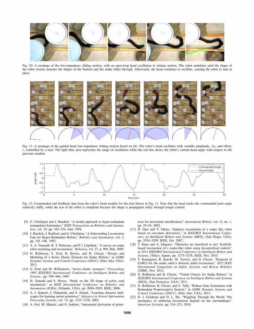
This allowed for compliance similar to the rest of themodules while propagating high amplitude waves throughthe backbone curvature. Even with the implementation of thissimple controller, the robot was able to successfully negotiatethe obstacles in a surprisingly life-like manner, as shown inFig. 10 and the supporting video. Although this method ofblindly oscillating the torque of the head module is compliantto the surrounding environment, it should be noted that itis an extremely naive way of setting and propagating thesliding motion. It often results in erratic behavior, like therobot turning around at the end of Fig. 10.
In order to steer heading direction and the overall motionof the robot, we can instead control the head module’s jointangle,
1097
θhead = Aθ sin(ωt) + ε. (8)
In (8) Aθ is the amplitude, ε is offset and ω is a fixedfrequency of oscillation. ε is used to steer the head moduleand thereby control the direction of the robot. Aθ is usedto begin and sustain oscillations in the robot in the casesof low backbone curvature as well as maintain some of theopen-loop controller’s ability to wriggle past obstacles.
This controller was tested in a random field of 5 cm (2 in)peg obstacles, shown in Fig. 11. The parameters Aθ and εwere controlled by an operator in real time using a joystick.The resulting head joint angles and the values of Aθ andε are shown in Fig. 12. Using this manual controller, weinferred that the head angle offset, ε, is by itself sufficientto control the heading direction of the robot, but that somebaseline oscillation, Aθ > 0, was needed to reliably propelthe robot forward. We have also intuitively inferred that Aθand ε together can be used to control the radius of turningduring locomotion.
VII. CONCLUSIONS AND FUTURE WORK
Torque control is a vital component to achieving adaptiveand compliant motions with any robot. For snake robots wehave presented three different torque control strategies thathave been implemented on a physical snake robot. With allof the controllers, the robot was able to actively adapt to itssurrounding environment, even without tactile sensing or anyother form of exteroceptive sensing. With a simple manualcontroller, we were able to intuitively steer the robot throughan irregular test environment. That said, this work is in a verypreliminary stage, and future work is continuing on all threemethods.
A. Compliant Roll-In-Shape
The controller presented in Section III depends solely onthe curvature of the robot along its backbone and serves asa general starting point for creating more complex motions.One interesting avenue of future work will involve tuning thecommanded torque based on the overall shape of the robot.For example, a useful motion could be rolling along theground but being compliant to small obstacles like rocks andgaps. The controller presented here tends to wrap the robotaround obstacles, rather than roll over them. One strategyto address this issue could involve adjusting the desiredtorques to allow tighter curvatures in one dimension and stiffcurvatures in an orthogonal dimension, based on the robot’soverall shape [20]. Alternatively, the torques could also beadjusted based on the estimated pose of the robot [21].
B. Empirical Gait Construction
We presented initial results in constructing a low-impedance version of the slithering gait. Although limited,this identical approach can be applied to other position-controlled gaits or motions. Future work will involve general-izing and parameterizing these new low-impedance motions,so that they can be easily adjusted online, like traditionalposition-controlled gaits the we currently use. To do this, we
intend to draw on existing work that has focused on learningcontinuous trajectories and controllers from demonstrationfor humans and humanoid robots [15], [16].
C. Low-Impedance Sliding
This control strategy is extremely interesting because itseems to closely mimic the motions of biological snakes [22].The simple controller presented in Section V works well inconfined spaces, but tends to perform poorly when the shapeis not well-constrained. One possible solution could be todevelop schemes that shift from executing the sliding motionto executing feedforward gaits like those in Section IV, de-pending on the presence of obstacles. Work is also underwayto incorporate other sensor data such as IMUs and encodersto automatically adjust the head steering parameters. Finally,we are working on combining the commanded torque (7)and position (8) functions for steering the head module intoa unified function which controls the direction of the robot,while at the same time allowing head of the robot to becompliant.
The characteristics of the skin of the snake also play anextremely important role during sliding motion [22]. Weare investigating other low-friction, or possibly directional-friction, skins to aid in sliding over a wider range of surfaces.If coupled with forms of active propulsion along the spine ofthe robot, like tracks or small wheels, it is possible that thissliding control strategy could provide exceptional mobilityover rough terrain.
VIII. ACKNOWLEDGEMENTS
The authors would like to thank Leif Jentoft and GillPratt for their work in simulating low-impedance torquecontrol for snake robots, which laid the groundwork for mostof Section IV. This work was funded by the DARPA M3program.
REFERENCES
[1] G. Chirikjian and J. Burdick, “The kinematics of hyper-redundantrobot locomotion,” IEEE Transactions on Robotics and Automation,vol. 11, no. 6, pp. 781–793, 1995.
[2] H. Ohno and S. Hirose, “Design of slim slime robot and its gait oflocomotion,” Proceedings 2001 IEEE/RSJ International Conference onIntelligent Robots and Systems., pp. 707–715, 2001.
[3] M. Tesch, K. Lipkin, I. Brown, R. L. Hatton, A. Peck, J. Rembisz,and H. Choset, “Parameterized and Scripted Gaits for Modular SnakeRobots,” Advanced Robotics, vol. 23, pp. 1131–1158, June 2009.
[4] S. Hirose, Biologically Inspired Robots. Oxford University Press,1993.
[5] A. J. Ijspeert, “Central pattern generators for locomotion control inanimals and robots: a review.,” Neural Networks, vol. 21, pp. 642–53,May 2008.
[6] D. Rollinson and H. Choset, “Gait-Based Compliant Control forSnake Robots,” in IEEE International Conference on Robotics andAutomation (ICRA), (Karlsruhe, Germany), pp. 5123–5128, 2013.
[7] D. Rollinson, Y. Bilgen, B. Brown, F. Enner, S. Ford, C. Layton,J. Rembisz, M. Schwerin, P. Velagapudi, A. Willig, and H. Choset,“Design and Architecture of a Series Elastic Snake Robot,” inIEEE/RSJ International Conference on Intelligent Robots and Systems(IROS), (Chicago, USA), IEEE/RSJ, 2014.
[8] P. Liljeback, K. Pettersen, O. Stavdahl, and J. Gravdahl, “ExperimentalInvestigation of Obstacle-Aided Locomotion With a Snake Robot,”Robotics, IEEE Transactions on Robotics, vol. 27, no. 4, pp. 792–800, 2011.
1098
Fig. 10: A montage of the low-impedance sliding motion, with an open-loop head oscillation to initiate motion. The robot undulates until the shape ofthe robot closely matches the shapes of the buckets and the snake slides through. Afterwards, the head continues to oscillate, causing the robot to turn inplace.
Fig. 11: A montage of the guided head low-impedance sliding motion based on (8). The robot’s head oscillates with variable amplitude, Aθ , and offset,ε, controlled by a user. The light blue area represents the range of oscillation while the red line shows the robot’s current head angle with respect to theprevious module.
0 5 10 15 20 25 30−1.5
−1
−0.5
0
0.5
1
1.5
time (sec)
angl
e (r
ad)
Commanded AngleActual Angle
Fig. 12: Commanded and feedback data from the robot’s head module for the trial shown in Fig. 11. Note that the head tracks the commanded joint anglerelatively stiffly, while the rest of the robot is compliant because the shape is propagated solely through torque control.
[9] G. Chirikjian and J. Burdick, “A modal approach to hyper-redundantmanipulator kinematics,” IEEE Transactions on Robotics and Automa-tion, vol. 10, pp. 343–354, June 1994.
[10] J. Burdick, J. Radford, and G. Chirikjian, “A Sidewinding LocomotionGait for Hyper-Redundant Robots,” Robotics and Automation, vol. 3,pp. 101–106, 1993.
[11] A. A. Transeth, K. Y. Pettersen, and P. l. Liljeback, “A survey on snakerobot modeling and locomotion,” Robotica, vol. 27, p. 999, Mar. 2009.
[12] D. Rollinson, S. Ford, B. Brown, and H. Choset, “Design andModeling of a Series Elastic Element for Snake Robots,” in ASMEDynamic Systems and Control Conference (DSCC), (Palo Alto, USA),2013.
[13] G. Pratt and M. Williamson, “Series elastic actuators,” Proceedings1995 IEEE/RSJ International Conference on Intelligent Robots andSystems., pp. 399–406, 1995.
[14] H. Yamada and S. Hirose, “Study on the 3D shape of active cordmechanism,” in IEEE International Conference on Robotics andAutomation (ICRA), (Orlando, USA), pp. 2890–2895, IEEE, 2006.
[15] A. J. Ijspeert, J. Nakanishi, and S. Schaal, “Learning attractor land-scapes for learning motor primitives,” Advances in Neural InformationProcessing Systems, vol. 15, pp. 1523–1530, 2002.
[16] A. Fod, M. Mataric, and O. Jenkins, “Automated derivation of primi-
tives for movement classification,” Autonomous Robots, vol. 12, no. 1,pp. 39–54, 2002.
[17] H. Date and Y. Takita, “Adaptive locomotion of a snake like robotbased on curvature derivatives,” in IEEE/RSJ International Confer-ence on Intelligent Robots and Systems (IROS), (San Diego, USA),pp. 3554–3559, IEEE, Oct. 2007.
[18] T. Kano and A. Ishiguro, “Obstacles are beneficial to me! Scaffold-based locomotion of a snake-like robot using decentralized control,”in 2013 IEEE/RSJ International Conference on Intelligent Robots andSystems, (Tokyo, Japan), pp. 3273–3278, IEEE, Nov. 2013.
[19] T. Kamegawa, R. Kuroki, M. Travers, and H. Choset, “Proposal ofEARLI for the snake robot’s obstacle aided locomotion,” 2012 IEEEInternational Symposium on Safety, Security, and Rescue Robotics(SSRR), Nov. 2012.
[20] D. Rollinson and H. Choset, “Virtual Chassis for Snake Robots,” inIEEE/RSJ International Conference on Intelligent Robots and Systems(IROS), (San Francisco, USA), 2011.
[21] D. Rollinson, H. Choset, and S. Tully, “Robust State Estimation withRedundant Proprioceptive Sensors,” in ASME Dynamic Systems andControl Conference (DSCC), (Palo Alto, USA), 2013.
[22] D. I. Goldman and D. L. Hu, “Wiggling Through the World: Themechanics of slithering locomotion depend on the surroundings,”American Scientist, pp. 314–323, 2010.