157
GOOD MORNING
| Date post: | 24-Dec-2015 |
| Category: |
Documents |
| Upload: | vasundhra-mittal |
| View: | 622 times |
| Download: | 79 times |

GOOD MORNING

TORQUE IN ORTHODONTICS
Introduction
Proper buccolingual inclination of anterior and posterior teeth is essential to provide better esthetic, stability and functional occlusal relationship. With Edgewise appliance Torque or buccolingual inclination was achieved by third order bends placed in arch wire. With Begg appliance inclination was achieved with auxiliaries. But today, majority of orthodontic brackets are pretorqued, so there is no need to give third order bend in the arch wire.

But in reality it is not so. So many factors affects the torque expression. It may be biological factors or mechanical factors. Moreover if the orthodontist does not have an understanding of torque, many adverse tooth movements will result, making orthodontic treatment more difficult and treatment results less desirable

Definition Torque being more related to engineering
terms is defined as
“The force system transmitted by and through a structural or machine member, capable of producing pure rotational displacement about the longitudinal axis”.

In Orthodontics, as stated by Dr. EARMAN D. RAUCH:
“Torque is the force that enable the orthodontist to control the axial inclination of the teeth and to place them in the harmonizing positions that are so desirable for a nicely finished results. Torque is the force that gives the operator control over the movement of the roots of the teeth”.
Torque is a force that assists him to bring about a desirable change of point A & B which in turn helps to bring about desirable facial changes in his patients.
BIOMECHANICS OF TORQUE Torque or root movement of a tooth is achieved by
keeping the crowns stationary and applying a moment to force only to the root.
This basic concept is better understood if the role of moment to force ratio is known.
The centre of rotation of a tooth is at the incisal edge in case of root movement.
The M/F ratio should at least be 12:1 to achieve root movement.
According to Dr. Ravindra Nanda M/F ratio of 5:1 causes UNCONTROLLED TIPPING M/F ratio of 7:1 causes CONTROLLED TIPPING M/F ratio of 10:1 causes TRANSLATION M/F ratio of 12:1 causes ROOT MOVEMET

Proffit has stated that the perhaps simplest way to determine how a tooth will move is to consider the ratio between moment created when force is applied to crown (MF) and counterbalancing moment generated by a couple within the bracket (MC).
MC/MF = 0 results in PURE TIPPING
MC/MF < 1 results in CONTROLLED TIPPING
MC/MF = 1 results in TRANSLATION
MC/MF >1 results in TORQUE
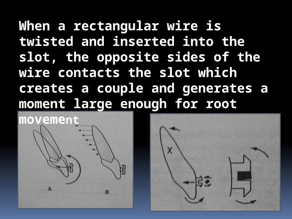
When a rectangular wire is twisted and inserted into the slot, the opposite sides of the wire contacts the slot which creates a couple and generates a moment large enough for root movement

Torque
WHY……….?
WHEN…………….?
& HOW…………?

why torque is necessary ……? To bring about labiolingual movement of
the teeth To retain the teeth in the cortical bone To avoid relapse To give a natural finish to the dentition

When.....?
When there is uncontrolled tipping of the crown
In third order bends of finishing and artistic positioning in a pre adjusted edgewise system.
In pre surgical and post surgical phases for the precise placement for axial inclination of teeth
As a device to augment anchorage demands of that particular situation.
How…..? Torque can be done both in fixed and removable
machanotherapies Torque in fixed appliance can be employed in
different ways 1. By giving a twist in an arch wire
– commonly used in edgewise techniques 2. Torque exerted by the bracket itself
– Pre adjusted edgewise appliance 3. By use of torquing auxiliary
- widely used in Beggs technique and edgewise technique.

ARMAMENTARIUM:
METHODS OF TORQUING IN
VARIOUS APPLIANCE MECHANICS
EDGEWISE MACHANOTHERAPY :
The edgewise arch appliance is the last of many contributions of Dr.EDWARD H. ANGLE and was introduced to the profession by one of his last students, Dr.ALLAN G. BROADIE in 1929. It is an exacting appliance requiring the thorough understanding and skill manipulation. This technique offers excellent controls in the labiolingual, mesiodistal and vertical dimension

The classification of tooth movement associated with edgewise appliance seem to be based upon the type of movements rather than direction. i. Movement of the First orderii. Movement of the Second orderiii. Movement of the third order
We will see here movement of the Third Order
Before we go into it we will have quick view over glossary

Passive torque – torque for proper placement of the wire
Active torque – for active tooth movement Progressive torque- increase of the torque value
progressively as we go posteriorly in the dentition
Torque force is named according to the action upon the tooth crown. 1. Lingual torque –
2. Labial or buccal torque –
19
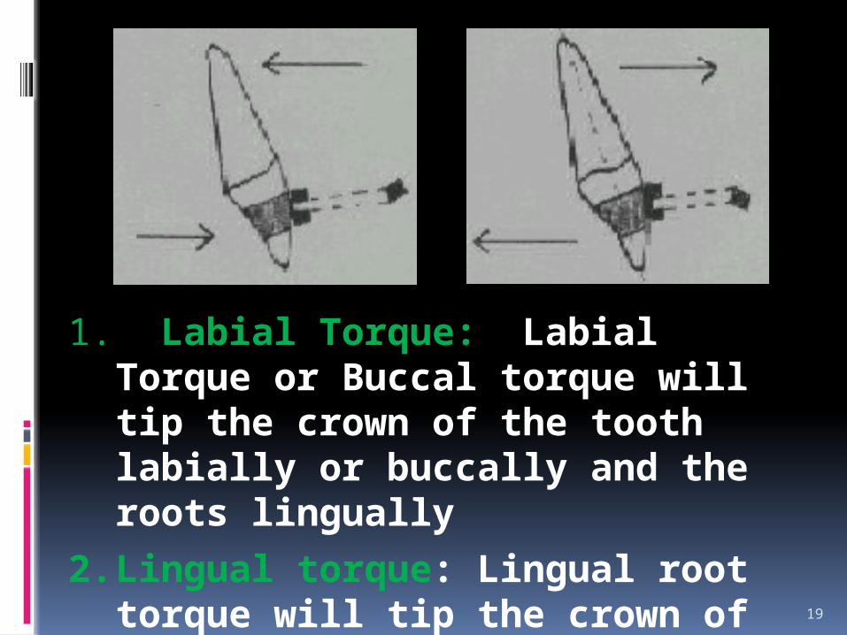
1. Labial Torque: Labial Torque or Buccal torque will tip the crown of the tooth labially or buccally and the roots lingually
2. Lingual torque: Lingual root torque will tip the crown of the tooth lingually and the roots labially or buccally
THIRD ORDER MOVEMENTS :
It is defined as the difference in inclination of the facial plane of crown at its mid point in an ideal occlusion.
The third order bends better known as torque are placed in the arch wire to effect buccolingual or labiolingual root and crown movements in a single tooth or a group of teeth

Torque requirements in maxillary and mandibular arch wire
For ideal axial inclinations, there should be lingual root torque in both maxillary and mandibular anterior teeth.
The arch wire should have lingual crown torque in the mandibular posterior teeth and to ensure good occlusion canine do not require any torque.

Anterior torque The basic criteria is
that the wire must fill the bracket i.e.. the diagonal dimensions of the wire must exceed the occlusogingival width of the bracket slot in order to maintain the twist activation.
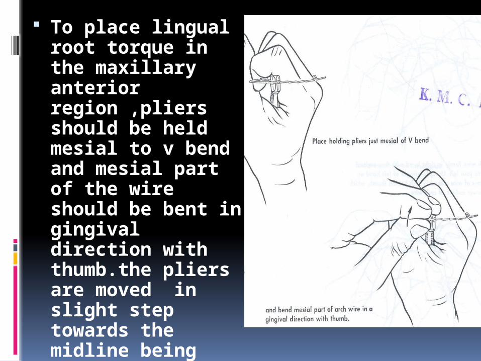
To place lingual root torque in the maxillary anterior region ,pliers should be held mesial to v bend and mesial part of the wire should be bent in gingival direction with thumb.the pliers are moved in slight step towards the midline being bent in a gingival direction with thumb.the entire arch has a lingual root torque now.


To remove lingual root torque from posterior legs the arch wire should be held just distal to v bend with another plier mesial to v bend the distal leg should be twisted in incisal direction until the omega loop or stop is again vertical.

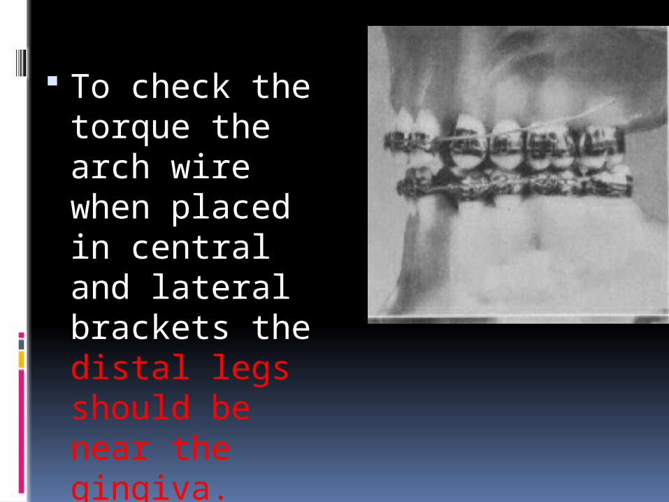
To check the torque the arch wire when placed in central and lateral brackets the distal legs should be near the gingiva.
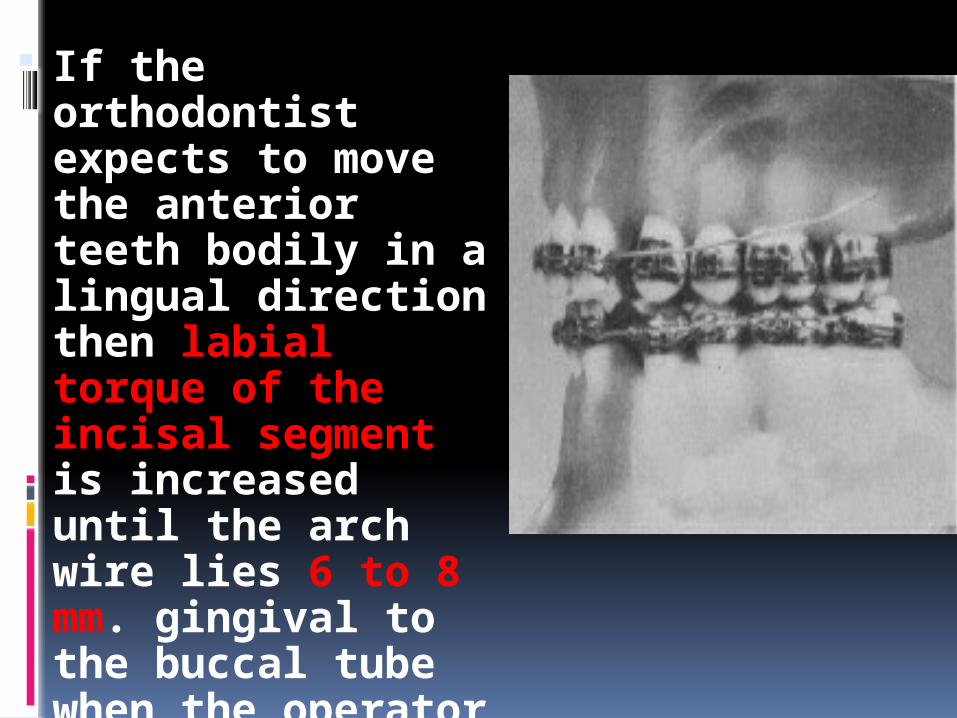
If the orthodontist expects to move the anterior teeth bodily in a lingual direction then labial torque of the incisal segment is increased until the arch wire lies 6 to 8 mm. gingival to the buccal tube when the operator tests for labial torque by placing the wire in the brackets of the anterior teeth.

Posterior torque
Continuous Progressive

Continuous posterior torque


Progressive Posterior Root Torque
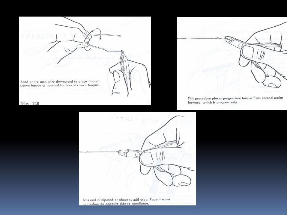

Brodie first called attention to the fact that, in order to have mass torque action in the buccal segment, progressive torque is necessary; otherwise, when the wire is inserted in the bracket of the cuspid tooth, the bracket removes the torque action from the teeth distal to the cuspid tooth, and the wire lies passive in the brackets of each succeeding tooth until the cuspid tooth movement has been accomplished.

TORQUE IN THE
PRE ADJUSTED EDGEWISE APPLIANCE
PRE ADJUSTED EDGEWISE APPLIANCE:
Until the mind 1970’s most fixed appliance therapy was carried out using the standard Edgewise bracket, either in a single or twin from having a 900 bracket base and brackets slot angulation.
The Major disadvantage resulted from this treatment are; 1. Arch wire bending is time consuming and tedious.
The short comings of the bracket system and the extreme skill required of the orthodontists resulted in many under treated cases and the results are appeared artificial
Molars were not in true CL-I relationship. Upper incisor are under torqued . So the resulting occlusion had the appearance of a ‘nice orthodontic result’ rather that a pleasing natural dentition. And also the long term stability of tooth adjustment was compromised by failing to establish ideal tooth relationships.
Against this background Dr.Lawrence
F.Andrews developed the straight wire appliance which became widely available in the mid 1970’s. It was hailed by the clinician’s as a radical step forward offering the dual advantages of less wire bending, coupled with an improved quality of the finished cases

TORQUE IN FACE VS TORQUE IN BASETorque in base was an important issue with the 1st and 2nd generation PEA brackets because level slot line up was not possible with brackets designed with torque in the face.Torque in base ,as said by Andrews, is a pre requisite for a fully programmed appliance.Albert H Owen (1980) conducted a study comparing Roth prescription and Vari Simplex Discipline. He concluded that while torque in base had a strong theoretical basis, its effectiveness is greatly influenced by clinician’s success in accurately placing brackets.

Torque in base means that bracket stem is parallel and coincides with long axis of bracket slotThe torque in face, slot is cut at an angle to the bracket stem. The long axis of slot does not coincide with bracket system.
UNDESIRABLE EFFECTS OF HAVING TORQUE IN THE FACE:
i) Bracket having torque in the face affects the final vertical positioning of tooth. ii) Level slot line up is not possible. iii) Bracket wings could bend or distort under various forces of ligation.
Torque in the bracket base allows flexibility of design. It enhances bracket strength and other features such as depth of the wing and labio lingual profile.
Modern bracket systems including MBT system have been developed using CAD CAM tech. Brackets may be finished with torque in the base ( full size or clear) or combination of torque in base or face ( mid size) with absolutely no difference in slot position.

43
Crown inclination is determined by the resulting angle between a line 90 degrees to the occlusal plane and a line tangent to the middle of the labial or buccal clinical crown.

TORQUE NORMS IN VARIOUS PRESCRIPTIONS
ANDREWS STRAIGHT WIRE APPLIANCE (SWA)Considered as the first generation of PEAThis appliance was constructed on the basis of a
collection of 120 non orthodontic models selected on the basis of occlusions that could not be anatomically improved upon with orthodontic therapy.
The average values from the non orthodontic normal sample were used to construct a hybrid edgewise appliance in which all three dimensions for tooth positioning for each tooth was built directly into the bracket.
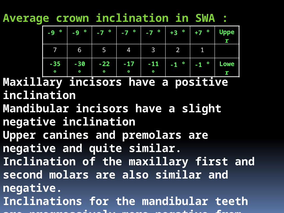
Average crown inclination in SWA :-9 ° -9 ° -7 ° -7 ° -7 ° +3 ° +7 ° Upper
7 6 5 4 3 2 1
-35 ° -30 ° -22 ° -17 ° -11 ° -1 ° -1 ° Lower
Maxillary incisors have a positive inclinationMandibular incisors have a slight negative inclinationUpper canines and premolars are negative and quite similar. Inclination of the maxillary first and second molars are also similar and negative.Inclinations for the mandibular teeth are progressively more negative from the incisors to the molars.

ROTH PHILOSOPHYRoth selected brackets from Andrews SWA set up and developed the Roth treatment and prescription.These were made available in 1976 and they are considered as the second generation of PEA.The three main reasons for the Roth prescription were as follows:
To reduce the need for a large and expensive inventory where one set of brackets could be used for a wide variety of cases
Anchorage Loss: Roth believed that mesially angulated brackets on posterior teeth tend to tip the teeth mesially and let them migrate forward resulting in possible anchor loss.
Over Correction : Roth propagated a therapy goal in which at the end of treatment all teeth were positioned slightly overcorrected and from which the would most likely settle into a non orthodontic normal position.
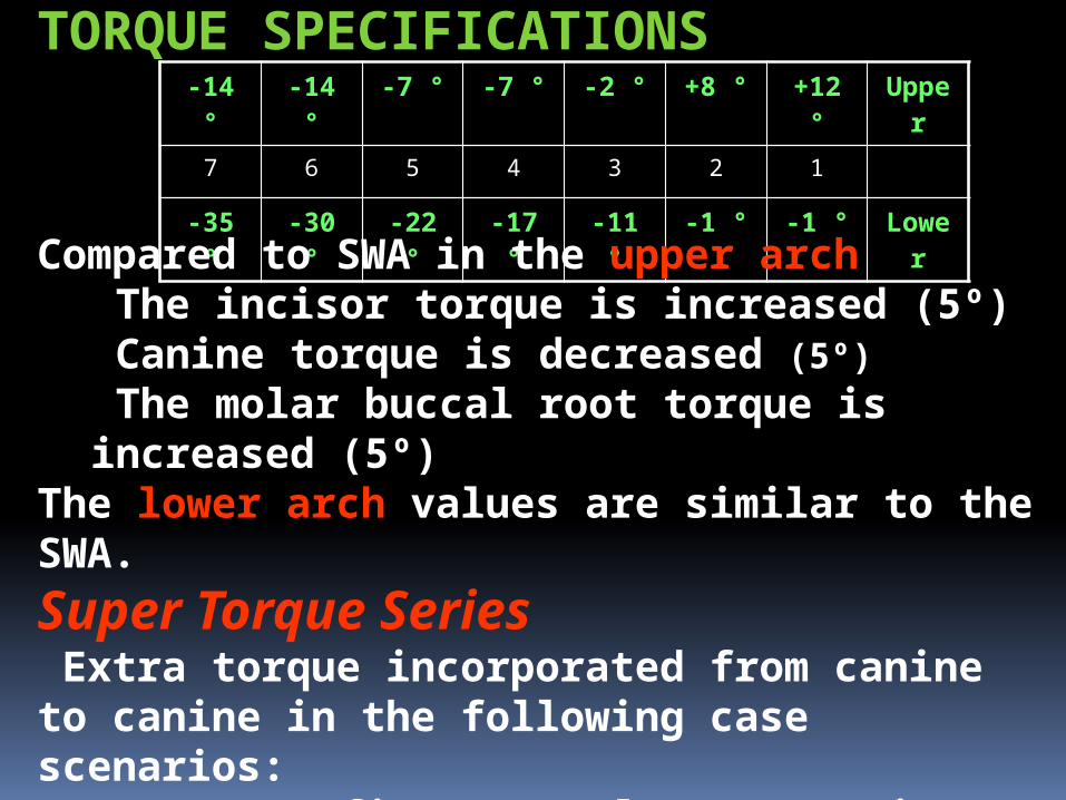
-14 ° -14 ° -7 ° -7 ° -2 ° +8 ° +12 ° Upper
7 6 5 4 3 2 1
-35 ° -30 ° -22 ° -17 ° -11 ° -1 ° -1 ° Lower
TORQUE SPECIFICATIONS
Compared to SWA in the upper arch The incisor torque is increased (5º) Canine torque is decreased (5º)
The molar buccal root torque is increased (5º)The lower arch values are similar to the SWA.
Super Torque Series Extra torque incorporated from canine to canine in the following case scenarios:
Two upper first premolar extraction casesAlso used in Class II div 2 cases and in any cases that require 6mm or more upper anterior retraction

MBT PHILOSOPHYMclaughlin, Bennett and Trevisi redesigned the entire standard bracket system to complement their proven treatment philosophy and to overcome the inadequacies of SWA.They re-examined Andrew’s original findings and took into account of additional research input from Japanese sourcesThis 3rd generation bracket system is designed for use with light continuous forces, lacebacks,bendbacks and sliding mechanics.
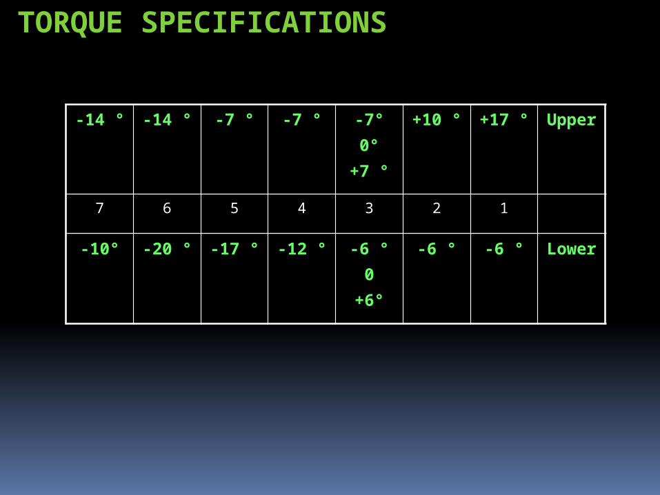
TORQUE SPECIFICATIONS
-14 ° -14 ° -7 ° -7 ° -7°0°
+7 °
+10 ° +17 ° Upper
7 6 5 4 3 2 1
-10°
-20 ° -17 ° -12 ° -6 °0
+6°
-6 ° -6 ° Lower
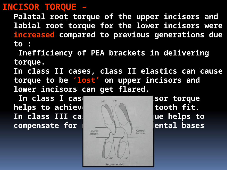
INCISOR TORQUE – Palatal root torque of the upper incisors and labial root torque for the lower incisors were increased compared to previous generations due to : Inefficiency of PEA brackets in delivering torque.In class II cases, class II elastics can cause torque to be ‘lost’ on upper incisors and lower incisors can get flared. In class I cases, correct incisor torque helps to achieve good anterior tooth fit.In class III cases correct torque helps to compensate for mild class III dental bases

CANINE TORQUEUpper canines: Torque in the upper canines are necessary because they are key elements in a mutually protected occlusion. The goal is to deliver ideal tip and torque to the canines so that they can fulfill their role in lateral excursions and have a small amount of freedom in maximum intercuspation.MBT uses two canine brackets for three torque options ( +7°, 0°, -7 °)Lower Canines: Original SWA torque in canine is not satisfactory because -11 ° tends to leave lower canine roots too prominent in some cases.MBT uses two canine brackets for three options (+6 °, 0 °,-6 °)

SELECTION OF CANINE TORQUE OPTIONS1. ARCH FORMSWell developed arches and substantial tooth
movement not requiredUpper Canine: -7 °Lower Canine: -6 °In cases of ovoid arch formsUpper Canine: 0 °Lower Canine: 0 °In cases of narrow (tapered) archUpper Canine: +7 °Lower Canine: +6 °2. CANINE PROMINENCE-7 ° in the upper arch or -6 ° in lower arch canine torques are normally not correct if the patient has prominent canines or canine gingival recession at start of treatment, in these cases bracket with 0 ° or +7 °/+6 ° should be used.

3. EXTRACTION DECISION: 0 ° brackets tend to maintain canine roots in the cancellous bone making tip control of roots easier.4. OVERBITE:In some Class II div 2cases, there is a requirement to move lower canine roots labially and also centre the roots in bone. This is more easily achieved if 0 ° or +6 ° lower canine torque is used.5. RAPID PALATAL EXPANSION CASESRPE of upper arch creates a secondary widening of the lower arch. There are torque changes associated with this. Values of 0 ° or +6 ° brackets are recommended to assist in the favourable change.6. AGENESIS OF UPPER LATERAL INCISORS If one or both lateral incisors are missing, a decision may be made to close spaces and bring canines mesially. It is helpful to invert -7 ° upper canine 180 °, thus changing the torque to +7 ° with the tip remaining the same.

UPPER PREMOLAR AND MOLAR TORQUEUpper premolar value of -7 ° has proven to be satisfactory in clinical use and the authors continue to work with it.For upper molars, -9 ° of original SWA has proven to be inadequate. They prefer -14 ° as it gives better control on palatal cusps and prevents the cusps from hanging down

LOWER PREMOLAR AND MOLAR TORQUEMany orthodontic cases have narrow maxillary arches with lower arches showing compensatory narrowing. These cases normally require buccal crown torque of lower premolars and molars. The original SWA first molar torque (-30 °) and 2nd molar torque (-35 °) allowed ‘rolling in’ of the lower molars.
WHY SO MUCH OF VARIATION IN TORQUE IN PEA???

VARIABILITY OF TORQUE IN PEATorque prescription varies from 7° for the maxillary central incisor in the SWA to 17° in MBT and 22 ° in Bioprogressive Rx.This lack of uniformity may be attributed to :The value that the developer chose as the
average normal inclination of the tooth surface.The expected ‘play’ in the bracket between the
arch wire and the slot.Position of the bracket on tooth surface. The
appliance meant to be placed rather gingivally have different torque values than one placed incisally.
AJO DO 2004; 125:323-28
VARIABLES AFFECTING TORQUE IN PEA:
•Variation in the shape of individual tooth• ‘Play’ of the arch wire•Variations in bracket placement•Manufacture errors in brackets and wires•Mode of ligation
AJO DO 2004; 125:323-28

1.VARIATION IN THE SHAPE OF INDIVIDUAL TEETH:
Theoretically for these brackets to apply torque implied by prescription, they should be positioned at the same point at which average torque values were first obtained - L.A point.With basic morphologic differences in the individual tooth shape and different recommended bracket placement charts of various prescriptions, clinicians donot use the L.A. point and therefore torque applied to tooth varies from prescription. AJO DO 1989; 96:312-09

2.PLAY OF THE ARCH WIRE
Filling the bracket slot by incrementally increasing the wire cross section has been the basic sequence of therapeutic protocols. Inevitably, a fraction of torque that is built into the bracket remains unexpressed owing to ‘play’ or ‘3rd order clearance’ or ‘slop’. Inability in full expression of built in torque in PEA is perhaps one of its biggest shortcomings. The average ‘play’ values vary with different clinicians and researchers.


3. VARIATIONS IN BRACKET PLACEMENT With PEA brackets, the position of brackets on crown
determines the tooth’s final tip, torque, height and rotation. Poorly positioned brackets result in poorly positioned teeth
and necessitate many more arch wire adjustments. This can lead to an increase in treatment time or final
occlusion that is less than ideal. Errors in the vertical dimension can alter the torque values
built into the appliance Meyer and Nelson stated that the mandibular 1st premolar
has the greatest occlusogingival curvature of any tooth and that a 3 mm displacement of the bracket results in a 10 ° alteration in applied torque
In addition thickness of composite and cement material under brackets and tubes may be another factor that changes the effective torque AJO DO 2001; 119:76-80AJO DO 1978; 73:485-90

4. VARIABILITY OF ACTUAL vs REPORTED TORQUE Manufacturing of brackets allows for an acceptable variation in their size and characteristics including dimensional accuracy and torque consistency.Wires and slots cannot be made precisely every time. Manufacturing tolerances result in 0.018” slots ranging from 0.017” to 0.019” whereas 0.022” slots ranging from 0.021” to 0.023”Bracket manufacturing process involving casting, injection moulding etc. can affect the accuracy of prescribed torque values.Various bracket slot manufacturing defects such as incorporation of metal particles in the slot, enlargement of the slot or decrease in the wire cross section can prevent the full engagement of the wire into the bracket slot which affects the torque expression. AJO DO 1993; 104:8-20

Other means taken to prevent the undesirable event is the rounding and bevelling the edges of both arch wire and slot. This makes insertion of wire easier In a study done by William Brantley et al (1984), it was found that in 0.022 slot the 0.019” x 0.025” β Titanium wire produced a play of 22 ° as compared to 12 ° in stainless steel. They concluded that edge bevel is expected to be a critical factor for actual torque expression by specific round or rectangular wire. So increase in edge bevel means increase in play.

5. MODE OF LIGATION A source of torque control loss is force relaxation in elastomeric ligatures. Elastomeric ligatures have shown a force degradation pattern characterized by initial decrease of nearly 40 % in the first 24 hrs. Thus the engagement of the wire to slot is flexible and incomplete resulting in further reduced expression of the already compromised torque.The use of steel ligatures has been found to diminish slot wire clearance.
So as a bottom line, a clinician might actually require more torque than incorporated into the currently available PEA and alternatively sufficient activation should be applied to arch wires to compensate for play, various manufacturing defects and clinical procedures which counteract the expression of torque built into the bracket.

TORQUE CONTROL IN VARIOUS TREATMENT STEPS
LEVELING AND ALIGNINGContrary to popular belief torque is not expressed only in rectangular SS wires.
Flexibility of the rectangular HANT wires allows early placement and this allows easier torque control than was possible when only steel wires were available

BITE OPENING CURVES AND TORQUEIn majority of the cases after rectangular stainless steel wires have been in place for 4-6 weeks, arches are normally aligned and adequate bite opening would have taken place if 2nd molars were banded , if this is not so then bite opening curves can be placed in rectangular steel wiresPlacing bite opening curves in the upper arch wire increases palatal root torque to upper incisors. This is beneficial in majority of cases and it is usually unnecessary to add any additional torque bends. When a reverse curve is placed in the lower rectangular wire result is proclination of lower incisors. This generally is not indicated. Thus before placement of bite opening curves in lower wire approximately 10 ° to 15 ° of labial root torque can be added
SPACE CLOSURE AND TORQUEAll research evidence shows the de merits of using Ni Ti coil springs for more rapid space closure. If space is closed too rapidly, incisor torque is lost and requires several months to regain the lost torque.Loss of torque control results in upper incisors being too upright at the end of space closure with spaces distal to the canines and a consequent unaesthetic appearance. Also rapid mesial movement of the upper molars can allow the palatal cusps to hang down resulting in functional interferences. Rapid movement of the lower molars causes ‘Rolling in’ of molars.

According to Raymond Siatkowski (1999) there is an average torque loss of 5 ° in the retraction of 1.3mm in maxillary arch and 1.2mm in the mandibular arch. This means that there is an average of 15 ° torque loss for 4mm of retraction.

TORQUE IN FINISHING AND DETAILINGTorque in maxillary incisors is critical in establishing an aesthetic smile line, proper anterior guidance and a solid Class I relationship. Under torqued incisors deprive the dental arch of space. It has been shown that for every 5 ° of anterior inclination 1mm of arch length is generated.Under torqued posterior segment has a constricting effect on the maxillary arch. (BJO 1999;26:97-102)A major finishing consideration in the horizontal plane is co ordination of tooth fit in the anterior and posterior areas. Any discrepancy in the tip, torque or tooth size can affect tooth fit.

Providing adequate incisor torqueTorque control is the weakness of PEA . Three factors
responsible are.1. Area of torque application
Approximately 1mm segment of rectangular steel wire is placed in a bracket slot of about the same dimension.
This segment is required to carry out rather difficult tooth movement which involves moving an entire portion of root through alveolar bone.
2. ‘Play’ between arch wire and slot.3. Upper and Lower anterior torque need of different
patients vary greatly.So,there is a need to place additional palatal root torque in
upper incisors and labial root torque in the lower incisors.

Providing adequate posterior torqueThough the MBT bracket system has been provided with additional buccal root torque compared to SWA, extra buccal root torque needs to be added to posterior segments of upper arch wire in certain cases.To provide adequate buccal root torque in the upper arch, it is also important to have a wide enough maxilla.If the maxilla is not wide enough, then buccal cortical plates will not allow for incorporation of appropriate amount of buccal root torque. This in turn leads to palatal cusps that create interferences during labial excursions and compromises to functional occlusion.This need to be evaluated carefully at the beginning of treatment
.
The earliest slotted bracket appliances relied on precious metal wires for activation. Gold wires were efficient and resilient in the first standardized slot size : the 0.022 inch.In the 1930’s stainless steel alloys were introduced and orthodontists soon replaced gold alloys with cheaper SS wires despite the realization that steel wires were less flexible than the equivalent sizes in gold.Clinicians in the 1950’s began employing smaller sized wires in the 0.022 inch slot. The mood was now right for a downsizing of edgewise slot dimension from 0.022 to 0.018 to allow light forces with SS.Some edgewise folks switched, some did not! Indeed the slot size dichotomy persists even today: 0.018 or 0.022!?
0.018 or 0.022 slot?

TORQUE EXPRESSION : 0.018” Vs 0.022” SLOT
The 0.018” brackets usually has 0.017” x 0.025” as working wire which has a slop of 6°. Thus theoretically torque expression in the 0.018” slot maybe better than in an 0.022” slot.
But the 0.018” slot has a host of other short comings: i)Torque prescription for the 0.018” slot tends to be more
conservative.ii) There is an obvious limitation in choice of wires and
treatment mechanics employed.iii) They are not efficient in sliding mechanics since the
0.017” x 0.025” wire does not have sufficient clearance and can be deflected . Loop mechanics has its own side effects of excessive forces and operator errors.

In the 0.022” slot, the slop of 10 ° with a 0.019”x0.025” arch wire must be counteracted by adding torque (10 °- 15 °) into the arch wire for utilizing complete built in prescription.In PEA the 0.022” slot is preferred because of the following advantages:
During leveling and aligning, these slots have definite advantage in choice of alignment wires.
0.022” slots are designed for sliding mechanics which is proven to be more efficient in space closure.
As adjunct with PEA, ( fixed functional, orthopedic forces, surgical cases) we require stiff, full size arch wires to avoid deflection. Thus 0.022” slots are more efficient.
DOES ONE PRESCRIPTION APPLY TO ALL? Factors such as age, sex, ethnic group are important in making a proper orthodontic treatment plan. Another important factor is the facial growth pattern and its general clinical characteristics.Faciolingual inclinations in PEA are relative to the occlusal plane. Occlusal planes are oriented differently in head when extreme variations in vertical growth proportionally occurs.Use of any PEA will orient the dentition to an occlusal plane that is different in different growth patternsHigh angle skeletal patterns: upright maxillary incisors and increased buccal inclination of posterior teeth Low angle skeletal pattern: More proclined maxillary incisors related to the SN plane and increased lingual inclination of the posterior teeth.
AJO DO 1993; 104:8-20
AJO DO 1990; 98:422-9
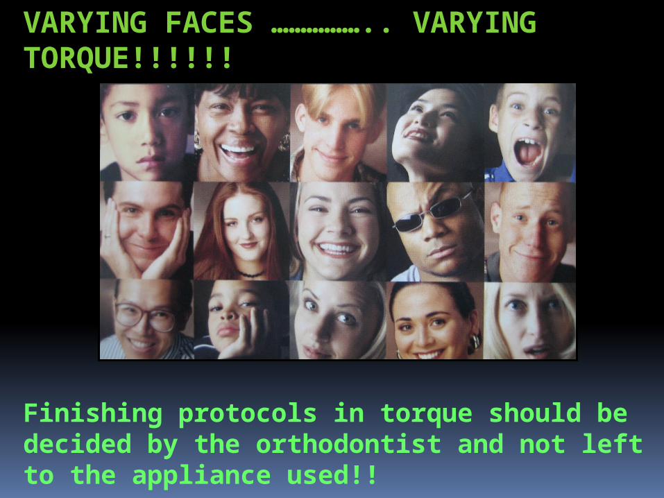
VARYING FACES …………….. VARYING TORQUE!!!!!!
Finishing protocols in torque should be decided by the orthodontist and not left to the appliance used!!

Torque in BEGGS MECHANOTHERAPY

BEGGS MECHANOTHERAPY : The torquing in BEGG is testimonial to the
genius Dr.BEGG, both with regards to its concept and the designs. The special feature of BEGG appliance in separating the tooth moving forces from the arch wire forces gives at a unique advantage. Various torquing auxiliaries developed Dr.BEGG the
1. Spur design having 2,4 and 6 pairs 2. Mouse-strap for lingual root torque 3. Udder arch for labial root torque4. Reciprocal lateral torquing auxiliary 5. Reverse torquing auxiliary6. KITCHTON torquing auxiliary
Single root torquing auxiliary developed Dr.Kesling
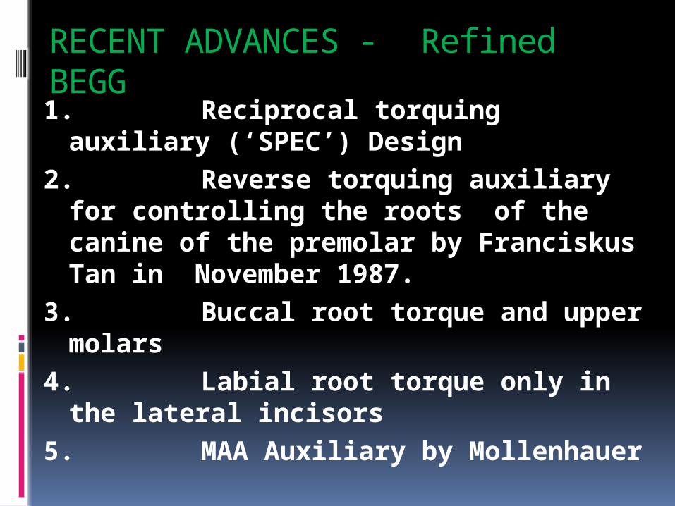
RECENT ADVANCES - Refined BEGG
1. Reciprocal torquing auxiliary (‘SPEC’) Design
2. Reverse torquing auxiliary for controlling the roots of the canine of the premolar by Franciskus Tan in November 1987.
3. Buccal root torque and upper molars
4. Labial root torque only in the lateral incisors
5. MAA Auxiliary by Mollenhauer

TORQUING AUXILIARY WITH SPURS
Action of the torquing auxiliary1. The auxiliary bent into a small circle,
when fixed in the mouth, is spread out along the wider anterior curvature of the arch wire. The lingual torquing effect is an account of two factors.
a. Firstly, the vertical plane in which the torquing auxiliary orients when fitted on two central incisors, is changed to a horizontal plane of arch wire when fully tied to it.

b. Secondly, when the torquing auxiliary is opened to a larger arc of anterior portion of the arch wire it rolls inwards.
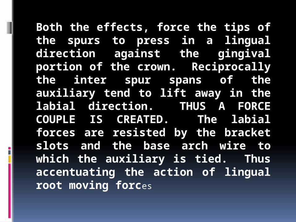
Both the effects, force the tips of the spurs to press in a lingual direction against the gingival portion of the crown. Reciprocally the inter spur spans of the auxiliary tend to lift away in the labial direction. THUS A FORCE COUPLE IS CREATED. The labial forces are resisted by the bracket slots and the base arch wire to which the auxiliary is tied. Thus accentuating the action of lingual root moving forces

ABOUT “THE SPUR”
1. The Auxiliary should be constructed in 0.012 premium plus wire (preferable pulse straightened) unlike in 0.014 or 0.016 special plus wire which were previously used.
2. The length of the spur does affect the force produced. A short spur will produce much greater force that will drop rapidly when the teeth start getting torqued, as against a longer spur that produces a gentler and more constant force.

The length of the spur should be kept at about 5 mm; but it should be varied depending on the clinical crown height, leaving it about 1 mm short of the gum to facilitate proper hygiene

3. Inclination of the spurs to the horizontal (occlusal) plane is kept 00. In other words, the activation is 100%.
4. The distal leg of every spur is kept slightly shorter by about 0.5 mm, so that the distal leg does not project incisally to the main arch wire on tying
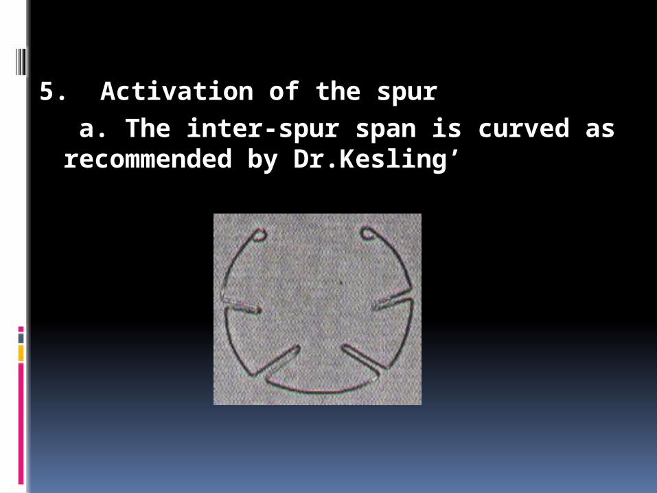
5. Activation of the spur
a. The inter-spur span is curved as recommended by Dr.Kesling’

b. Kept straight as shown in Swain’s chapter

c. Angulated midway as in BEGG

d. As recommended by Dr.Jayade – normally size of the old 50 paise coin
The force generated by the auxiliary increase with decrease in the diameter in the circle and vice-versa

Two of the modification commonly required in the spur design torquing auxiliary are as follows.
a. Reverse labial torque on one or both the lateral incisors : Boxes at right angle to the plane of the spurs are made to lie at the incisal area of the lateral incisor(s). Crossover bends are made on either side of the lateral incisor bracket to permit the auxiliary to pass over the base wire, similar to the bends described in the section on the MAA
Torquing boxes on the canines for lingual root torque : Instead of making spurs for the canines, boxes can be provided. The ends of this auxiliary need not extend beyond the canine area

MAA auxiliary was developed by Dr.
MOLLENHAUER and it was given the name as “An Aligning Auxiliary for Ribbon Arch Brackets”. The MAA, attempts root control from the very beginning, of the treatment without significantly affecting the anchorage and overbite correction. This has become possible by using a combination of a stiff base arch wire made from 0.018” Premium plus, and ultra light root moving forces from the MAA made from the 0.009” Supreme grade wire
MOLLENHAUER’S ALIGNING AUXILIARY (MAA) AND ITS MODIFICATIONS

Requirements for use of the MAA
Mollenhauer has enumerated the requirements as
1. It must generate very light root moving forces. Therefore, the wire size must not exceed 0.009”.
2. For the same reason, when reciprocal torque is required on adjacent teeth, the adjacent rectangles must not diverge by more than 45 degrees.
3. At the same time, the auxiliary must be able to resist deformation. Hence, it must be made in a highly resilient wire viz. Supreme grade (preferable pulse straightened)

4. The base wire should be able to resist the vertical and transverse reactive forces from the MAA. Therefore, it must be made in 0.018” Premium Plus wire.
5. In Mollenhauer’s application, the MAA is always engaged first and the main wire is engaged piggyback. The rectangles for lingual root torque lift away from the tooth surface, which are held down with the help of pins, thus indirectly transmitting the torquing action through the pins to the brackets onto the teeth.
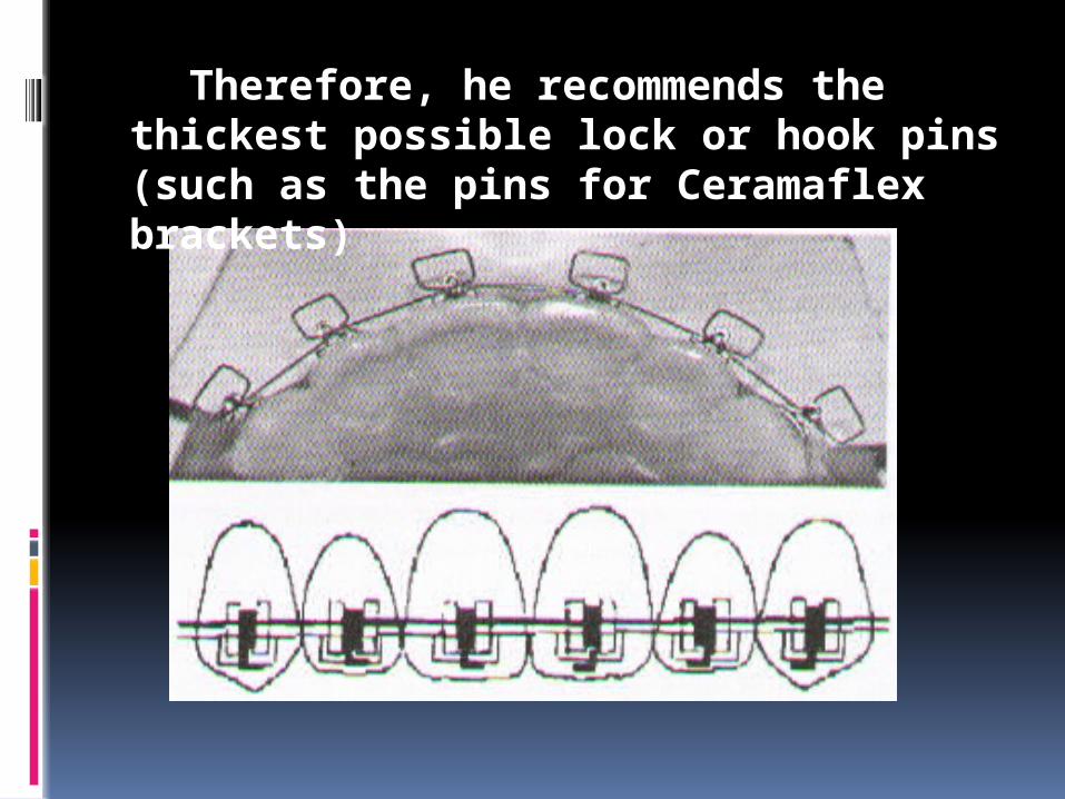
Therefore, he recommends the thickest possible lock or hook pins (such as the pins for Ceramaflex brackets)
Advantages of the MAA
According to Molenhauer, the advantages of MAA are :
1. Efficacy in intrusion and advantages retraction of the anterior teeth,
2. Efficiency in rapid bodily alignment of the anterior teeth
using gentle forces
3. Stable results.
4. Reciprocability of torquing forces on the in standing laterals or palatally placed canines.

5. Periodontal advantages in such cases, because the gingival dehiscence associated with prolonged labial root torquing of such teeth during the 3rd stage is eliminated.
6. A short stage III, because the early root control minimizes (uncontrolled) root tipping in the opposite direction
7. Possibility of growing cortical bone at the A and B points

VARIOUS APPLICATIONS OF THE MAA
1. Originally, the MAA was introduced for bodily alignment of crowded teeth. The looped arch wire like effect (expansion + de rotation + vertical leveling) was combined with lingual and / or labial root torque

VARIOUS APPLICATIONS OF THE MAA
2. By bending more positive torque into the MAA, it can be used after the stage I as a braking mechanism.
Mollenhauer strongly recommends applying labial root torque on the lower incisors in growing brachyfacial cases, to prevent their roots from lingualizing (which can happen due to intrusive forces and due to contraction of trans-septal fibers in extraction cases). This helps in a better profile control. The MAA can be used for labial root torque on the upper incisors in Class III cases
3. In later writings, Mollenhauer described use of the same auxiliary for controlling the mesio-distal root positions from the beginning. He called this application ‘MAA-tip. A ligature wire tied to the auxiliary and to the pin transfers the tipping effect to the tooth.

4. Modification can be used for reciprocal root torque

Other boxed Auxiliaries
Mini versions of MAA ranging from 0.009” to 0.012” and curvatures facing incisally facing incisally or gingivally, for labial or lingual root control respectively. They are employed on two or more number of anterior teeth in either or both the arches. The force exerted by the boxes is varied, as per the individual requirement, by varying the diameter of the wire from which the auxiliary is made, size of the boxes and acuteness of the curvature.

Obviously, the auxiliaries generating lighter forces are employed in the first and second stages of treatment, while those generating higher forces are meant for the third stage and sometimes in the second stage as a breaking mechanics
a. Two boxes on the upper central incisors for lingual root torque after the teeth are aligned
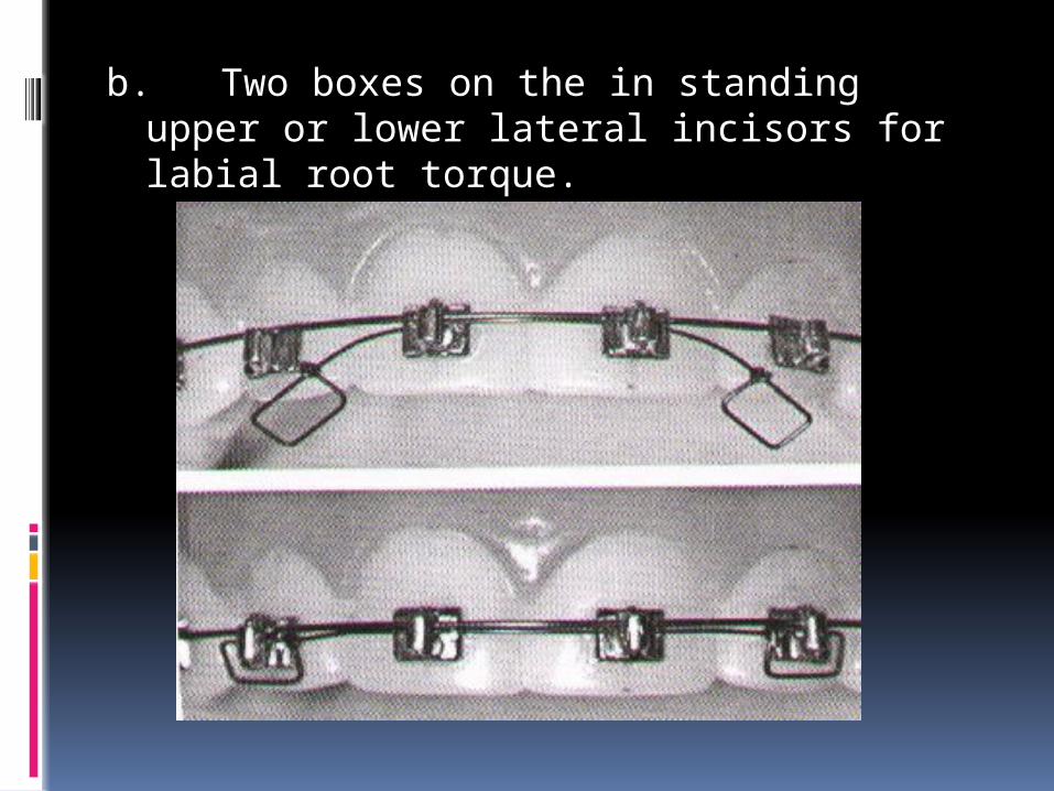
b. Two boxes on the in standing upper or lower lateral incisors for labial root torque.

‘Jenner’ auxiliary two boxes on the upper or lower canines with very prominent roots. That is made up of 0.012” wire. Lingual root torque exerted by the boxes reduces the prominence to facilitate anterior retraction

d. ‘SPEC’ design – Reciprocal torquing auxiliary – it is employed when two adjacent teeth require root torque in opposite directions. One such example is an in standing lateral incisor needing labial root torque and the adjacent canine needing lingual root torque. This auxiliary is made of lighter 0.009 or 0.010 could be used for controlling the root movements during the first and second stages.
If needed in stage three it should be made of 0.012.The box on the tooth requiring labial root torque is placed incisal to main wire, while the box on the other tooth requiring lingual root torque sits piggyback on the main wire .hence a crossover bend is required between the two adjacent teeth because the auxiliary has to cross over the main wire.varying the angulation between the planes of two boxes can control the force generated by the auxiliary


Some other torquing auxiliary designs
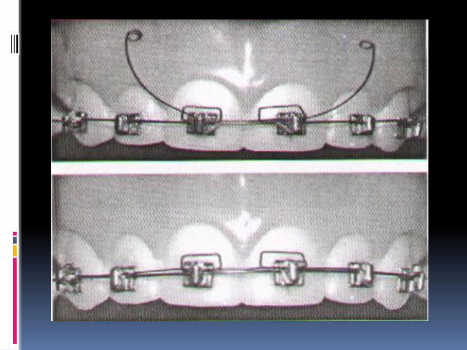
a.Single root torquing auxiliary proposed by Dr.Kesling’. This is a very useful design for any tooth (excepting the molars) requiring torque in the labial or the lingual direction. It is particularly indicated on an UPPER PREMOLAR , which needs buccal root torque. To eliminate the cuspal interference from its hanging palatal cusp. It is convenient to place the long arm of the auxiliary piggy back over the main arch wire. Since the main arch wire may not be untied it could also lie occlusal to the base arch wire in the slot as well. The long arm should extend to three to four adjacent teeth when engaged in the brackets.
The long arm always faces mesially for the premolar teeth. Depending on how the curvature is pointing before the auxiliary is tied, the torque generated will have lingual (palatal) or buccal root moving effect.
For example, the auxiliary fitted with its convexity facing upwards will have a buccal root torquing effect on the upper premolars, but the effect will be for lingual root torque on the lowers, and vice-versa. The effect is transmitted by the vertical extension of the auxiliary through the bracket pillar onto the tooth; The long arm could face either mesially or distally on the anterior teeth, and action will depend on how the curvature of the long arm relates to the base arch wire. This auxiliary is made up of 0.012 size Premium Plus wire. The force generated by it can be varied by changing acuity of the curvature. More acute greater is the force generated.

b. Reverse torquing auxiliary for controlling the roots of canines or premolars proposed by Dr.Franciskus Tan - It was described for the labial root movement of a palatally impacted maxillary canine, whose crown has been aligned but the root is still placed palatally and needs labial root torque. If required for lingual root torque in other situations it is simply inverted well on the premolars made up of 0.012” P+ wire conjunction with a 0.018” or 0.020” inserted in the molar tube from the distal end. An offset is placed in the auxiliary to bypass the main wire rotated by 1800 for activating it


c. Buccal root torque on the molars – When the upper molar crowns roll buccally because of a lack of control during the third stage, their roots must be torqued buccally to lift their palatal hanging cusps. It is made in 0.014” size and is fitted in the round molar tubes alongside the main arch wire. It has ‘boot’ design occlusal extensions on the molars, and it is inserted from the mesial end of the molar tubes. The boot portion is twisted lingually and given a toe in, and the whole auxiliary is suitable contracted. The auxiliary need not be engaged in other brackets. It can be ligated to the main wire at 2-3 places on either side
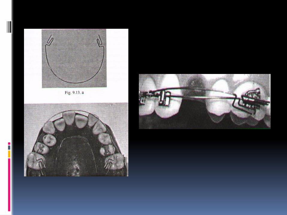
d. Labial root torque only on the lateral incisors – This is made up of 0.012” size wire, and is placed with the convexity of the auxiliary facing gingivally. The auxiliary is engaged first in the incisor brackets, and the main wire is then engaged piggyback. The boxes extend labially on the incisal area of the crowns. This design is often required on the lower incisors in those cases where the central incisors and the canines are placed normally, and hence do not require reciprocal lingual root torque

e. UDDER ARCH - The udder arch is made up of 0.16 S.S.wire. The vertical loops of the auxiliary can be opened or closed as needed to assume accurate fit. The distal ends of the auxiliary is tied to the lower cuspid bracket. The vertical loops are slipped behind the main arch wire and the auxiliary is tided to one or two brackets to prevent dislodgement. It is very easy to insert and remove. This is used for the reverse torquing of the mandibular incisors.

f. Kitchton torquing auxiliary - It is used for applying torque force on the anterior teeth. Kitchton auxiliary can be used with Begg, edgewise and removable appliances. It is made up of 0.016 Australian wire. Coils in the midline assume gentle, and continuous torque force and also provide means of attachment to the main arch wire.
It is of two types :
1) Small 2) Large
* Small auxiliary delivers gentle lingual root torque to the central incisors only. It can be used with the Hawley’s retainer for additional root torque.
Large auxiliary can deliver greater force to the central incisor and can be adjusted to deliver torquing force to the central and lateral incisors. It an also be used with Hawley retainer for additional root torque

Mouse trap
Mouse trap design is very efficient but involves more time patience and skill

Torque in Tip-Edge Appliance

123
Tip-Edge Appliance: Kesling introduced these concepts in 1986. Tip edge brackets are produced by removal of diagonally opposed corners from edgewise slot to permit either mesial or distal tip.
This was a preadjusted bracket slot. MAX Torque 12 8 -4 -7 -7 MAD Torque -1 -1 -11 –20 -20

124
In Tip Edge concepts, inclination of teeth except anchor tooth are normally not controlled until the final finishing stage. But exception for earlier axial control would be To correct Midline Discrepancy.For effective Anchorage controlTo prevent excess Tipping During stageIII depends upon the necessity of torquing action, Round wire ( 0.022 inch ) or Rectangular wires ( 0.0215 * 0.028 inch ) are used.

125
Round wire approach: (0.022 inch wire) Patients who doesnot requires molar torque Selective labiolingual root position of the tooth In severe AP discrepancy to maintain the compensating labiolingual inclinations.
Side-winder springs

126
They are invisible when placed in the slot because it lies behind the main arch wire.Characteristic of Tip edge bracket was presence of Deep groove in the slot. During Stage 1 and 2 a cap fills the deep groove. At the beginning of stage 3, the cap is removed and torquing bar is ligated tightly in to the deep groove under the round wire.
Niti torquing Bars: They are formed in 18*22 with 30 torque.

Standard Tip Edge Grooved Edgewise Cap closed Cap opened in stage 3
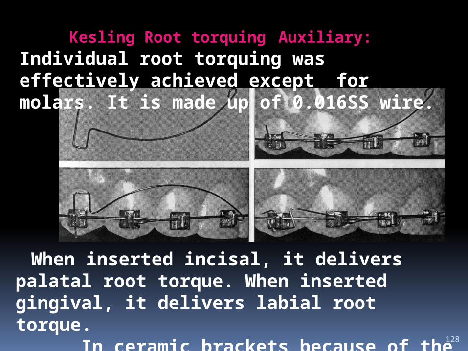
128
When inserted incisal, it delivers palatal root torque. When inserted gingival, it delivers labial root torque. In ceramic brackets because of the lack of Deep groove in the slot, this auxiliary is effectively used.
Kesling Root torquing Auxiliary: Individual root torquing was effectively achieved except for molars. It is made up of 0.016SS wire.
Rectangular wire approach: (0.0215*0.028 ) Patients who required molar torque, canine and mandibular incisor are candidate for rectangular wire approach. Deep bite During stageI and stageII, as crowns are tipped to the final position of the dental arches, Slot size will also get increased. This permits passive engagement of full size rectangular arch wire. Each tooth will have either one point or no contact with the arch wire. So the interbracket distance is from molar to molar which yields light and long lasting torquing forces

130
Torquing Features of Tip edge:
SELECTIVITY LIMITATION PHYSIOLOGIC
Advantages of this system: AJO 1998 Parkhouse
Independent torquing: Because the Side-Winder springs do not cause clinically detectable twisting of the heavy base arch wire, unwanted secondary torque reactions to adjacent teeth are eliminated.
Light forces: An auxiliary spring is less likely to generate excessive torque forces than an activated rectangular arch wire.
131
. Long activation span: Reactivation of the Side-Winder spring is not normally found to be necessary. However, additional activation may be required near the completion of treatment, for a precise definition of finishing torque angulation.
Single arch wire: All torquing can be accomplished using one rectangular arch wire in each arch. Adjustment of the arch wire is normally not required.
No lost torque: Because the bracket closes into complete approximation with the arch wire, the exact prescription is expressed without compensation being necessary for free play.
132
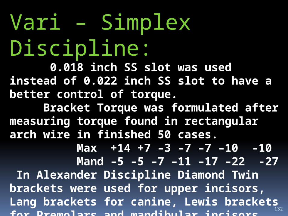
Vari – Simplex Discipline: 0.018 inch SS slot was used instead of 0.022 inch SS slot to have a better control of torque. Bracket Torque was formulated after measuring torque found in rectangular arch wire in finished 50 cases. Max +14 +7 –3 –7 –7 –10 -10 Mand –5 –5 –7 –11 –17 –22 -27 In Alexander Discipline Diamond Twin brackets were used for upper incisors, Lang brackets for canine, Lewis brackets for Premolars and mandibular incisors which adds advantage of increased interbracket distance.

133
Diamond Twin Bracket
Lang Bracket
Lewis Bracket

134
Rectangular multistranded arch wire was used from initial point of treatment itself.-3 Torque in maxillary canine compared to –7 to +7 in Andrews’s prescription eliminate the need for adjusting torque through wire bending during treatment. -5 Lower incisors torque prevents labial flaring of incisors. When omega loop was used in mandibular 2nd molar, to prevent gingival impingement bend was placed in the wire which automatically incorporates torque. So additional torque was
not necessary in 2nd molar. .

135
Bio-progressive therapy The Standard Bioprogressive appliance was introduced in 1962.
Dental reaction to continuous arch wire Max 22 14 7 0 0 -10 -10 Mand 0 0 7 0 -14 -22 -32
136
This system was based on sectional arch treatment in which the buccal segments are handled separately from the incisors for better torque control. It includes all cases whether non-extraction, or extraction treatment. Torque control throughout treatment is one of the basic principle of this technique. The Full Torque Bioprogressive appliance adds additional torque to the original Standard Bioprogressive setup to over torque the tooth at the time of band removal to settle in to functional occlusion.
137
In this technique the lower first molar is rotated disto-lingually, tipped distally, expanded, and torqued (buccal root torque) so that the roots come to lie beneath the adjacent buccal cortical bone. This is called as “cortical anchorage.” This is an area that exhibits a greater bone density because of the external oblique line of the mandible and decreased vascularity. By placing the roots of the lower first molar adjacent to the more dense cortical bone, anchorage is believed to be enhanced, thereby minimizing movement of the molar teeth. So Torque value of –27 in molar is used.

138
Upper buccal segment should have 10° of buccal root torque to compensate for the occlusogingival curvature of the crowns of these teeth. The lower molar cannot differentiate between buccal root and lingual crown torque ,when a 45° buccal root torque is placed on the distal legs of the utility arch. The only way that buccal root torque can be expressed by buccal movement of the root and stabilization of the crown is by expansion of the arch. This is not only for cortical bone support to the lower molar (anchorage) but also for regulating or allowing normal arch width.

139
Utility arch is designed to avoid contact on cortical bone on the lingual surface of the lower incisor roots during their intrusion by placing 15°-20° buccal root torque Cuspid Torque: +70 There is a mechanical tendency to detorque the upper cuspids as they are retracted in extraction cases. Because the dense cortical plate surrounding the upper cuspids is particularly corrugated (especially in adults), it is difficult to retract the cuspids without impacting the root on the labial plate. It is mechanically more efficient to keep the root of the cuspid in the cortical trough when moving it distally when using +70 torque. .

140
Parkhouse in AJO 1998 evaluated bioproggresive therapy and tweed appliance result and stability after 5 years of post retention. The result showed both cause molar extrusion and are stable. Incisor intrusion was more and clinically significant in bioprogressive theraphy Elizabeth and Bernard AJO 1998 done a comparative study of anchorage in bioprogressive versus standard edgewise treatment in Class II correction with Class II Elastics and showed cortical anchorage did not resist the side effects of Class II elastics more effectively than standard edgewise anchorage preparation.

Torque control in lingual orthodontics

Torque control in lingual orthodontics Decreased arch radius, decreased interbracket
distance, compound lingual geometry, highly variable tooth morphology, and limited access and visibility all combine to make accurate torque control exceedingly difficult with a lingual appliance.
Early torque control becomes more important with lingual brackets, because minor differences in labiolingual long axis inclinations of the incisors will show up as apparent height differences.
It can be disconcerting when a patient complains that incisor alignment is getting worse,

The TARG (Torque and Angulation Reference Guide) instrumentation is designed to transfer bracket prescriptions from the more reliable labial surfaces of each tooth to the lingual at a given bracket height.
This is in effect a method of doing a diagnostic set-up without sectioning the model, and it allows the laboratory technician to set customized torque and angulations for each individual prescription.
.

For example, a Class II, division 2 case requiring additional torque in the maxillary anteriors is so noted on the prescription.
The technician then "dials" in the prescribed torque on the TARG, locating the lingual bracket at an increased torque angle from the averaged bracket values. The fit of the lingual bracket base is then compensated for with the Advance adhesive.
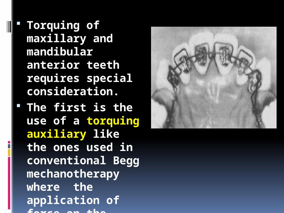
Torquing of maxillary and mandibular anterior teeth requires special consideration.
The first is the use of a torquing auxiliary like the ones used in conventional Begg mechanotherapy where the application of force on the tooth is at the incisal edge.

The second is the use of a torqued ribbon arch. It provides approximately 45 degrees of torque for the mandibular anterior teeth and 30 degrees for the maxillary anterior teeth.
When the ribbon arch passes the cuspid-bicuspid inset, it will naturally transition to approximately 90 degrees for the buccal segments.
Beta titanium, stainless steel, and Elgiloy rectangular wire may also be very useful for this purpose.
Hocevar has stated that the use of the ribbon arch is effective for torquing of maxillary anterior teeth, and it has the advantage of being more gentle in the buccolingual directions, a very important advantage with lingual orthodontic treatment.

Torquing With Removable Appliances

Torquing With Removable Appliances Many simple malocclusions can be treated with
removable appliances; but, since removable appliances are only capable of tipping crowns, it has not been possible to torque roots, particularly in cases with spacing of anterior teeth. In these cases, spaces can be closed effectively with removable appliances, but the anterior teeth have labial root prominence at the end of treatment.
To avoid this problem and the need for a fixed appliance to correct it, a new technique was developed for root tipping of anterior teeth with removable appliances
A removable appliance is constructed in a conventional manner, with Adams clasps on first permanent molars and triangular clasps between first and second premolars, for additional anchorage and to combat leverage in the anterior region.
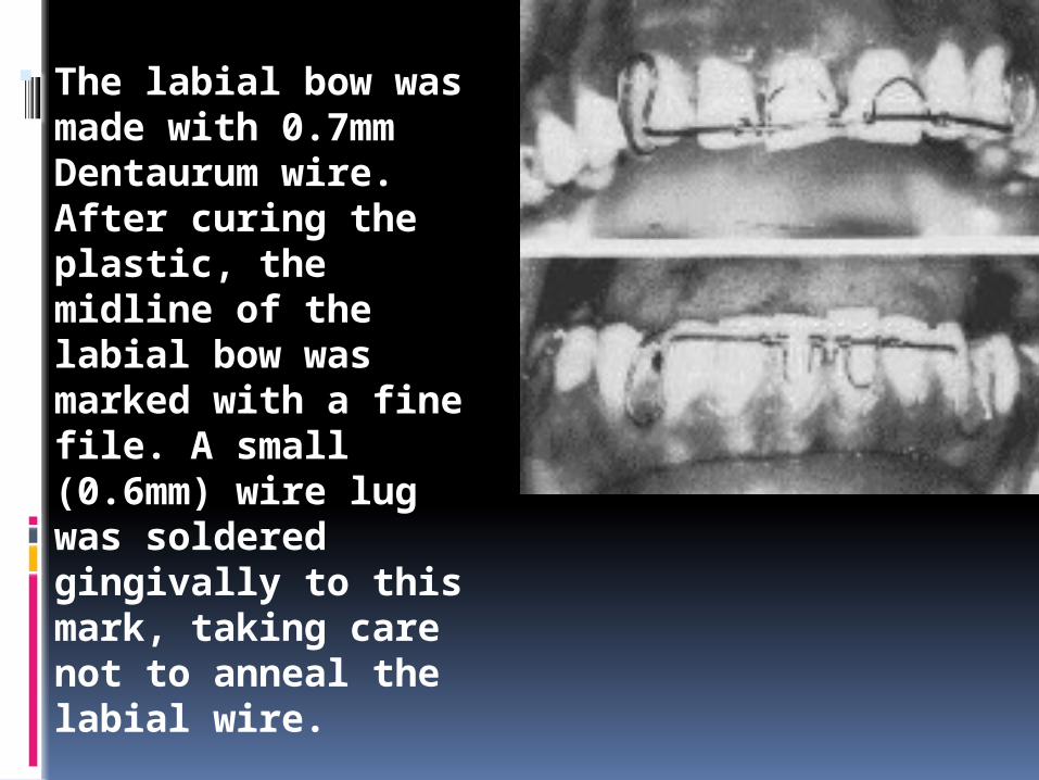
The labial bow was made with 0.7mm Dentaurum wire. After curing the plastic, the midline of the labial bow was marked with a fine file. A small (0.6mm) wire lug was soldered gingivally to this mark, taking care not to anneal the labial wire.

A torquing spring of 0.4mm spring wire was constructed by winding the wire
Winding must be started from the central lug. The finished loops are lingually inclined. The distal ends of the loops are not soldered or welded to the labial bow. Force is generated from the central lug, which resists the activation of the loops.
When the appliance is placed in the mouth, the loops exert pressure on the cervical third of the crown. The tip of the crown is prevented from coming labially by the labial bow. Thus, movement is restricted to lingual root tipping.
Torque considerations in adults
A routine torque by conventional edgewise arches is not always the recommended method.
In the anterior region of the adult teeth the lingual and labial cortical plates are frequently thin and dense. if the movement of the teeth is not performed carefully the apices of the teeth may be forced against the dense alveolar bone with the shortening of the root as result of resorption.
A second important point is that the center of resistance varies with alveolar bone height. The movement of teeth in adults with alveolar bone loss will be different than in adolescents.
A thin arch is preferable for torque movement in adults.
Light wire torque may also lead to root resorption if the force is acting for a long period.
In order to avoid root resorption the best technical solution would be to apply light torquing forces that acts interruptedly over a fairly short distance.
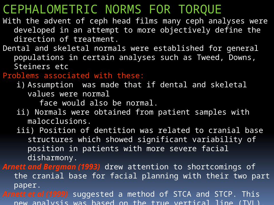
CEPHALOMETRIC NORMS FOR TORQUEWith the advent of ceph head films many ceph analyses were
developed in an attempt to more objectively define the direction of treatment.
Dental and skeletal normals were established for general populations in certain analyses such as Tweed, Downs, Steiners etc
Problems associated with these:i) Assumption was made that if dental and skeletal values were
normal face would also be normal.ii) Normals were obtained from patient samples with
malocclusions.iii) Position of dentition was related to cranial base structures
which showed significant variability of position in patients with more severe facial disharmony.
Arnett and Bergman (1993) drew attention to shortcomings of the cranial base for facial planning with their two part paper.
Arnett et al (1999) suggested a method of STCA and STCP. This new analysis was based on the true vertical line (TVL).

Incisor torque norms acc. To Dr ArnettUpper Incisor Lower IncisorF: 57º ± 2.5° M: 58º ± 3° F: 64º ± 3.2° M: 64 ± 4°
Why use maxillary and mandibular OP??Incisor measurements to distant landmarks such an Sella Nasion, FH plane , A-Po line may produce misleading measurements. Mandibular and palatal planes themselves are altered by surgical procedures so these are not good references for surgical cases.