Torsional rigidity in beams with arbitrary cross-sections A Thesis Submitted in Partial Fulfilment of the Requirements for the Degree of Bachelor of Technology in Mechanical Engineering by Sudeep Nayak Roll No: 110ME0317 Under the supervision of Dr. M. K. Moharana DEPARTMENT OF MECHANICAL ENGINEERING NATIONAL INSTITUTE OF TECHNOLOGY ROURKELA May 2014
Transcript
Torsional rigidity in beams with arbitrary
cross-sections
A Thesis Submitted in Partial Fulfilment of the Requirements for
the Degree of
Bachelor of Technology
in
Mechanical Engineering
by
Sudeep Nayak
Roll No: 110ME0317
Under the supervision of
Dr. M. K. Moharana
DEPARTMENT OF MECHANICAL ENGINEERING
NATIONAL INSTITUTE OF TECHNOLOGY ROURKELA
May 2014
i
This is to certify that the research work that has been presented in this thesis entitled
“Torsional rigidity in beams with arbitrary cross-sections” by Sudeep Nayak, has
been carried out under my supervision in partial fulfilment of the requirements for
the degree of Bachelor of Technology in Mechanical Engineering during session
2013-2014 in the Department of Mechanical Engineering, National Institute of
Technology Rourkela.
As per my knowledge this dissertation work has not been submitted in any
other college or university at any time prior to this, for the award of any degree or
diploma.
Dr. Manoj Kumar Moharana
(Supervisor)
Assistant Professor
Department of Mechanical Engineering
Date: 12/05/2014 National Institute of Technology Rourkela
NATIONAL INSTITUTE OF TECHNOLOGY ROURKELA
ii
ACKNOWLEDGEMENT
I would like to take this golden opportunity as a privilege to thank all individuals without whose
support and guidance I could not have completed our project in this stipulated period of time. I,
wholeheartedly, acknowledge the intellectual stimulation of my esteemed guide Dr. Manoj Kumar
Moharana, (Assistant Professor, Mechanical Engineering Department) for his continuous help and
guidance throughout the project in spite of his busy work schedule. He helped me out in
understanding the subject well & he always stood beside me whenever I needed his help. It is the
result of his sincere of co-operation that I finished my project in stipulated time
I am highly indebted to Department of Mechanical Engineering for providing necessary
information and guidance regarding the project and also for their support in completing the project.
And last but not the least, I would like to thank my friends and my family for their support.
Sudeep Nayak
Roll No:110ME0317
Department of Mechanical Engineering National Institute of Technology Rourkela
iii
Index
Item Page No.
Certificate i
Acknowledgement ii
Index iii
Abstract iv
1. Introduction 01
2. Motivation behind the present work 02
3. Literature survey 03
4. Generalization of stress function equations
i. Case 1 : Solid arbitrary cross-section 04
ii. Case 2 : Arbitrary cross-section with circular hole 09
iii. Case3 : Circular cross-section with arbitrary hole 12
5. Results and discussion 16
6. Conclusion 21
References 22
Appendix A : MATLAB code for calculating stress function in a bar with square
cross section 23
Appendix B : MATLAB code for calculating stress function in bar with square cross
section with cylindrical hole 24
Appendix C : MATLAB code for calculation of stress function in a bar cylindrical bar
with arbitrary shaped hole. 25
Appendix D : Variable declaration for MATLAB codes
26
iv
Abstract:
In solid mechanics, when a torque is applied on a body, the body twists. This is called torsion.
In those sections which are perpendicular to the torque axis, the resultant shear stress is in a
direction, perpendicular to that of the radius. Almost all the rotating parts of a machine
experience torsion and an accurate study of torsional study is essential for proper designing
of machine components so as to have desired physical properties . Structures with different
kind of cross-sections have different values of torsional rigidity. But currently, work has been
done to accurately find out the torsional rigidity of only standard beam structures (like
hexagonal etc.). In the present work, a semi analytical boundary collocation method has been
used to predict the torsional rigidity of any arbitrary shaped cross-sectional beams.
1
Introduction:
In the designing of structural elements, studying torsion is very important and quite basic. We may
formulate the problem in Laplace equation involving boundary values in case of a wrapping
function, or Poisson equation involving boundary value in the Prandtl’s stress function. There
exists exact solutions for standard cross sectional shapes like circular, triangular, elliptical, annular
and regular polygonal. With developments in computational capabilities, numerical techniques can
be used as an alternate for both standard cross-sectional as well as complicated shapes. The
boundary element method, the finite element method or finite differences method are the most
widely used methods. In the last two of the methods, complete cross-section needs to be discretized
to elements or grids. In order to make it accurate, it would require a large number of nodes and
elements for a complicated shape. Here, boundary collocation method comes into picture. In this
method, only the boundary needs to be discretized instead of the whole cross-section. A fast
development in the mesh free methods have been seen in the recent years. There are many of these
mesh free methods.
One of these mesh free methods is the Trefftz method. In this method, the solution of the partial
differential equation is expanded in respect of T-functions or the trial functions of the equation, as
a result, that equation is identically satisfied by the proposed approximate formula. We now apply
the boundary conditions in an approximate manner in order to determine the included expansion
parameters. Boundary collocation method is one of the simpler versions of the aforementioned
procedure. In this method boundary conditions are satisfied only at finite points along the
boundary. Hence it is considered as a semi analytical method as it provides analytical expressions
which are accurate in nature, which provide solutions through simple numerical calculations.
Boundary collocation method (BCM) has been applied by many authors for solving torsion
problems. There has been extensive work on such problems for solid bars having regular cross
sections like circular or polygonal. But relatively less work has been done on torsion problems in
complicated cross sections and even if some studies have been done, they take up the problems
individually. So there needs to be a generalization of such solutions.
2
This work involves the torsion in rods whose cross-section is arbitrary in nature. The objective of
this work is to present a generalized solution that can be applied to bars having any kind of cross-
section, with or without holes of any arbitrary shape, provided that, it has at least one plane of
symmetry. The theoretical analysis results in a situation where one requires to solve a set of linear
equations with a set of unknowns, thus requires use of numerical methods such as Gauss Seidel
technique. In the present work, MATLAB is used as a tool for this purpose.
Motivation behind the current work:
It was seen that the governing differential equation for stress functions are very similar to that of
the heat conduction as well as the fluid flow equations. Hence the stress equations can be
efficiently worked on parallel lines with the heat flow or the fluid flow equations, and that is what
has been done. The work includes:
Studying the heat diffusion equations and the application of boundary collocation technique
for solving them
Analyzing the BCM technique in lines with fluid flow problems
Studying the generalization of this technique for any arbitrary cross section
Generating governing differential equations for various cases viz. solid arbitrary cross-
section, arbitrary cross-section with cylindrical hole and cylindrical bars with arbitrary hole.
Using different boundary conditions to simplify and solve them using MATLAB.
Using MATLAB to generate coordinates of the profile and calculate stress function values.
Generating a contour plot from those values.
3
Literature survey:
Boundary collocation method has been used many a times in previous works, quite efficiently.
This method has been used in finding non dimensional torsional rigidity, in heat and fluid
equations as well. Kołodziej and Strek [1] worked on the shape factor concept in regular polygons.
For solving relevant boundary value related problems, they used the boundary collocation
technique involving least square approximation. They also presented elementary analytical
formulas which gives shape factors for the geometries that they have considered. Kolodziej and
Fraska [2] found out the non-dimensional torsional rigidity in regular polygonal beams by
integrating the equations of stress functions analytically for the several cases that have been taken
into account, the non-dimensional stiffness of rods were calculated using an analytical formula.
Numerical results were also shown for various cross-sectional shapes so as to show the accuracy
as well as the efficiency of the BCM. Moharana and Das [3] analyzed conduction through shaped
tubes with circular inner surface and hydrodynamically shaped outer surface by two different
techniques. They made a two-dimensional analysis by a semi analytical technique using boundary
collocation at the outer periphery. Moharana and Das [4] used boundary collocation technique to
find the heat flow through an eccentric insulation surrounding a circular cylinder. Moharana and
Khandekar [5] presented a generalized form for finding pressure drop in any arbitrary shaped
channel which may be singly or doubly connected using the boundary collocation method.
4
Generalization of stress function equations:
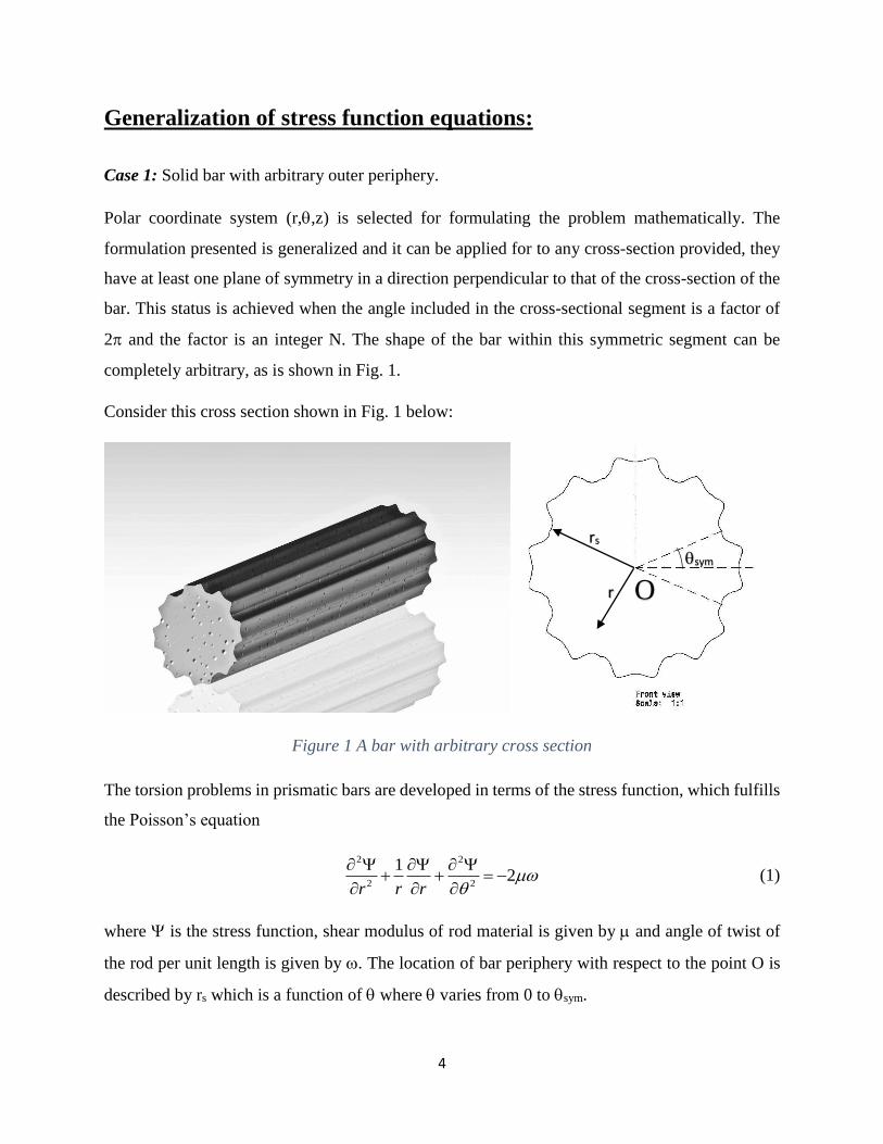
Case 1: Solid bar with arbitrary outer periphery.
Polar coordinate system (r,,z) is selected for formulating the problem mathematically. The
formulation presented is generalized and it can be applied for to any cross-section provided, they
have at least one plane of symmetry in a direction perpendicular to that of the cross-section of the
bar. This status is achieved when the angle included in the cross-sectional segment is a factor of
2 and the factor is an integer N. The shape of the bar within this symmetric segment can be
completely arbitrary, as is shown in Fig. 1.
Consider this cross section shown in Fig. 1 below:
Figure 1 A bar with arbitrary cross section
The torsion problems in prismatic bars are developed in terms of the stress function, which fulfills
the Poisson’s equation
2 2
2 2
12
r r r
(1)
where is the stress function, shear modulus of rod material is given by and angle of twist of
the rod per unit length is given by . The location of bar periphery with respect to the point O is
described by rs which is a function of where varies from 0 to sym.
sym rs
r O
5
Now we introduce non dimensional variables which are of the form:
2
, ,2
ss
rrR R
(2)
where ‘ℓ’ is any length scale that is required so as to non-dimensionalize. Length scales to be
considered based on the geometry i.e. varying from one geometry to another geometry; this has to
be fixed beforehand by inspection. Now the governing equation has the form:
2 2
2 2
11
R R R
(3)
The general solution for this governing equation is of the form:
2
1
1
( , ) ln ln4
(A )cos( )
(C )sin( )
k k
k k
k k k
k
k k k
k
RR B R C D R
R B R
R D R
(4)
Figure 2 Symmetric segment of the arbitrary cross section.
The sym Shown in the Fig. 2 is the angle of symmetry and a symmetric segment has also been
shown. The Fig. 2 shows a bar of arbitrary cross section and the figure alongside show one of its
sym Rs
sym R
Rs
O
6
symmetric angular segment ranging from = 0 to = sym. The boundary conditions in this case
are:
0
at = 0 (5)
0
at = sym = /N (6)
0 at R = Rs (7)
The solution of the above equation when subjected to boundary conditions as in Eq. (5) and Eq.
(6), we get an equation similar to:
2
( 1)
1
( , ) cos[ ( 1) ]4
N k
k
k
RR Y R N k
(8)
where Yk are the unknown coefficients.
Now, this Yk can be found by using the boundary condition as in Eq. (7).
At R = Rs, Eq. (8) becomes:
2
( 1)
1
cos[ ( 1) ]4
N ksk s
k
RY R N k
(9)
In this equation, the unknowns are Yk,where k varies from 0 to ∞. Nonetheless, the Eq. (9) cannot
be assessed certainly because of uniqueness in geometry of the outer surface which has any
arbitrary cross-section (rs is a function of ). In order to solve this problem, the BCM is applied at
a finite number of collocation points which are equidistant to each other and are present on the
arbitrary boundary. This arbitrarily shaped surface is defined uniquely by rs() within the limits
= 0 and = /N. Now, the infinite series which is represented in Eq. (9) is cut short to the first M
number of terms and Eq. (9) is satisfied at the collocation points considered on the non-circular
boundary. Hence we get M number of unknowns (Yk, k = 1 to M) and an equivalent number of
linear equations. So we may write Eq. (9) as a set of linear equations, the unknown constants being
represented by Yk, given by,
7
1
( )M
jk k j
k
G Y F
j=1,2,3… M (10)
where,
( 1) cos[ ( 1) ]N k
jk sG R N k (11)
2
4
sj
RF (12)
Now M values of have to be chosen and the selection of the values which again depends on the
problem. Angles were take such that the points are equidistant from each other. The system of
linear equations mentioned above, which is shown in Eq. (10), may be evaluated to determine the
values of the constants that are unknown i.e. Yk. Hence the complete stress function profile is
obtained and it is given by Eq. (8). After applying the BCM, we find out the values of coefficients
Y1, Y2, . . . ,YM and hence we get the formula for the stress function 𝜓 explicitly, i.e.
2
( 1)
1
( , ) cos[ ( 1) ]4
MN k
k
k
RR Y R N k
(13)
In order to arrive at a reasonably accurate solution, the number of points that has to be taken
depends on the complicacy of the arbitrary shape. Now, in order to find non-dimensional stiffness
of rods, we have to evaluate twisting moment in rods. Then the stress functions are integrated
analytically and a formula for the same is also found analytically for all the cases. Hence, torsion
in prismatic rods is given by:
2A
M dA (14)
where A is area of cross-section of the rod. The non-dimensional torsional stiffness of the rods
have the form:
4
MD
a (15)
8
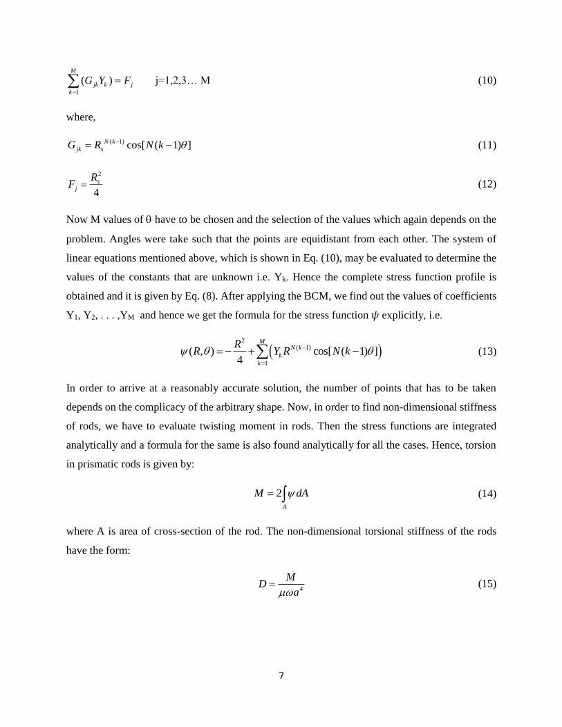
For the case 1, i.e. a solid arbitrary cross section, two such examples have been considered.
Example 1: Cross-section of the bar is a square. The bar of square cross section is shown below:
Figure 3 Bar of square cross section and its symmetric segment.
Now the equation of outer periphery in its angular symmetric segment ranging from = 0 to =
sym is given by: Rs = 1/cos(). No of symmetric segments N = 4.
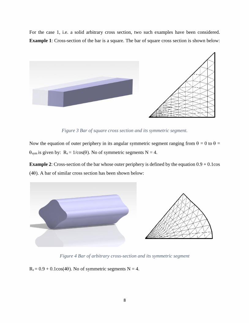
Example 2: Cross-section of the bar whose outer periphery is defined by the equation 0.9 + 0.1cos
(4). A bar of similar cross section has been shown below:
Figure 4 Bar of arbitrary cross-section and its symmetric segment
Rs = 0.9 + 0.1cos(4). No of symmetric segments N = 4.
9
The variation of stress function throughout the cross section was found out by incorporating the
method explained earlier in a MATLAB program (refer Appendix A). The coordinates were
obtained and the corresponding value of the stress function was obtained. A contour plot was made
and plot has been shown later.
Case 2: Bars with arbitrary outer periphery and a circular centered holes.
A bar of arbitrary cross-sectional shape having a circular centered hole is shown in Fig. 5 along
with the front view of the bar.
The non-dimensional variables required for the geometry (taking ℓ = ri) are as given as:
R = r/ri ; /s s iR r r (16)
Figure 6 Symmetric segment of the bar
Rs
R
sym
sym
Figure 5 Bar of arbitrary outer periphery with cylindrical hole and its front view
O
10
such that for the current geometry, 1 R Rs. A symmetric segment of this kind of cross section
has been shown in the Fig. 6.
The boundary conditions in a non-dimensional form are as given by:
0
at = 0 (17)
0
at = sym = /N (18)
0 at R = Rs (19)
0 at r = ri or R = 1 (20)
where, the value of 𝜓0 is chosen such that it satisfies the following condition:
2
0 1R
d
(21)
If we consider the same approach as in case 1, we get the stress function as:
2
( 1)
1 ( 1)2
( 1) 1( , ) cos[ ( 1) ]
4
N k
k N kk
RR Y Y R N k
R
(22)
where the unknown coefficients are Yk.
Now, this Yk can be found by using the boundary condition as in Eq. (19).
At R = Rs, Eq. (22) becomes:
2
( 1)
1 ( 1)2
( 1) 1cos[ ( 1) ]
4
N ksk s N k
k s
RY Y R N k
R
(23)
Now M values of have to be chosen and the selection of the values which again depends on the
problem. Angles were taken such that the points are equidistant from each other. After obtaining
the values of , and dropping the values for k>M the infinite series to first M terms, we get a set
of linear equations which helps in determining the values of Yk,
11
1( )
M
jk k jkG Y F
j=1,2,3… M (24)
where,
1 1,jG (25)
( 1)
( 1)
1cos[ ( 1) ]N k
jk s N k
s
G R N kR
(26)
2 1
4
sj
RF
(27)
Putting the values of Yk in Eq. (22), we find the value of stress function throughout the cross
section.
For the case 2, i.e. bars with arbitrary outer periphery and a circular centered holes, two such
examples have been taken.
Example 3: Outer periphery of the bar is a square with a circular centered hole. The bar of square
cross section is shown below:
Figure 7 Bar of square cross section with circular hole and its symmetric segment
Now the equation of outer periphery in its angular symmetric segment ranging from = 0 to =
sym is given by
Rs = 2/cos().
No of symmetric segments N = 4.
12
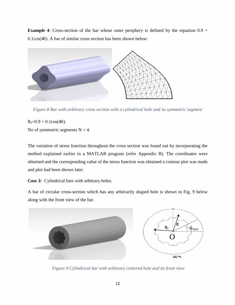
Example 4: Cross-section of the bar whose outer periphery is defined by the equation 0.9 +
0.1cos(4). A bar of similar cross section has been shown below:
Figure 8 Bar with arbitrary cross section with a cylindrical hole and its symmetric segment
Rs=0.9 + 0.1cos(4).
No of symmetric segments N = 4.
The variation of stress function throughout the cross section was found out by incorporating the
method explained earlier in a MATLAB program (refer Appendix B). The coordinates were
obtained and the corresponding value of the stress function was obtained a contour plot was made
and plot had been shown later.
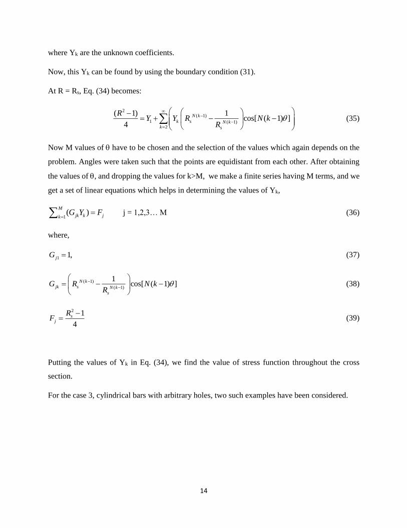
Case 3: Cylindrical bars with arbitrary holes.
A bar of circular cross-section which has any arbitrarily shaped hole is shown in Fig. 9 below
along with the front view of the bar.
Figure 9 Cylindrical bar with arbitrary centered hole and its front view
R sym Rs
O
13
The non-dimensional variables required for the above geometry (taking ℓ = ri) are as follows:
/ ; / ri s s iR r r R r (28)
such that for the current geometry, 1 R Rs. A symmetric segment of this kind of cross section
has been shown in the Fig. 10
The boundary conditions in a non-dimensional form are given by:
0
at = 0 (29)
0
at = sym = /N (30)
0 at R = Rs (31)
0 at r = ri or R = 1 (32)
where, the value of 𝜓0 is chosen such that it satisfies the following condition:
2
0sR R
d
(33)
If we consider the same approach as in case 1, we get the stress function as:
2
( 1)
1 ( 1)2
( 1) 1( , ) cos[ ( 1) ]
4
N k
k N kk
RR Y Y R N k
R
(34)
Figure 10 Symmetric segment of the bar
sym
14
where Yk are the unknown coefficients.
Now, this Yk can be found by using the boundary condition (31).
At R = Rs, Eq. (34) becomes:
2
( 1)
1 ( 1)2
( 1) 1cos[ ( 1) ]
4
N k
k s N kk s
RY Y R N k
R
(35)
Now M values of have to be chosen and the selection of the values which again depends on the
problem. Angles were taken such that the points are equidistant from each other. After obtaining
the values of , and dropping the values for k>M, we make a finite series having M terms, and we
get a set of linear equations which helps in determining the values of Yk,
1( )
M
jk k jkG Y F
j = 1,2,3… M (36)
where,
1 1,jG (37)
( 1)
( 1)
1cos[ ( 1) ]N k
jk s N k
s
G R N kR
(38)
2 1
4
sj
RF
(39)
Putting the values of Yk in Eq. (34), we find the value of stress function throughout the cross
section.
For the case 3, cylindrical bars with arbitrary holes, two such examples have been considered.
15
Example 5: Outer periphery of the bar is circular with a square centered hole. The bar of this kind
of cross section is shown below:
Figure 11 Bar of square cross section with circular hole and its symmetric segment
Now the equation of outer periphery in its angular symmetric segment ranging from = 0 to =
sym is given by
Rs = 1/cos().
No of symmetric segments N = 4.
Example 6: Cross-section of a cylindrical bar whose hole is defined by the equation (0.9/2) +
(0.1/2)cos(4). A bar of similar cross section has been shown below:
Rs = 0.9 + 0.1cos(4).
No of symmetric segments N = 4.
Figure 12 Bar of arbitrary cross section with circular hole and its symmetric segment
16
The variation of stress function throughout the cross section was found out by incorporating the
method explained earlier in a MATLAB program (refer Appendix C). The coordinates were
obtained and the corresponding value of the stress function was obtained and a contour plot was
made and plot had been shown later.
Results and discussion:
In the first case where we had taken a solid cross section, two examples were taken to illustrate
the working of the MATLAB code. Using MATLAB, (x,y) coordinates were obtained for the
profile and stress function values of various points were calculated and a contour plot was made,
and it was observed that at the periphery, because of absence of any force, stress function value is
minimum (theoretically zero) which is shown by the smaller values in stress function. As we
approach towards the center, that value increases. The value is maximum at the center.
Example 1:
R = 1/cos().
sym = 45.
No of symmetric segments = 4
Figure 13 Stress function for bar of square cross-section
Stress Function
17
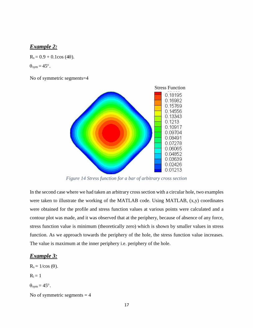
Example 2:
Rs = 0.9 + 0.1cos (4).
sym = 45.
No of symmetric segments=4
In the second case where we had taken an arbitrary cross section with a circular hole, two examples
were taken to illustrate the working of the MATLAB code. Using MATLAB, (x,y) coordinates
were obtained for the profile and stress function values at various points were calculated and a
contour plot was made, and it was observed that at the periphery, because of absence of any force,
stress function value is minimum (theoretically zero) which is shown by smaller values in stress
function. As we approach towards the periphery of the hole, the stress function value increases.
The value is maximum at the inner periphery i.e. periphery of the hole.
Example 3:
Rs = 1/cos ().
Ri = 1
sym = 45.
No of symmetric segments = 4
Figure 14 Stress function for a bar of arbitrary cross section
Stress Function
18
Example 4:
Rs = 0.9 + 0.1cos (4).
Ri = 1.
sym = 45.
No of symmetric segments = 4
Figure 15 Stress function for square bar with cylindrical hole
Figure 16 Stress function for arbitrary bar with cylindrical hole
Stress Function
Stress Function
19
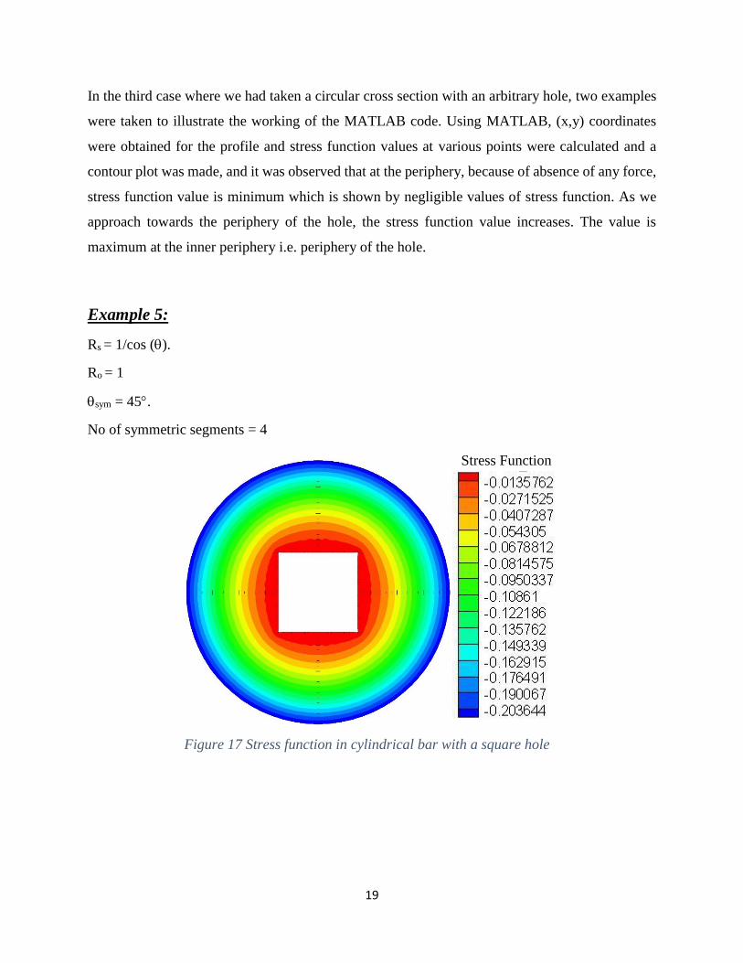
In the third case where we had taken a circular cross section with an arbitrary hole, two examples
were taken to illustrate the working of the MATLAB code. Using MATLAB, (x,y) coordinates
were obtained for the profile and stress function values at various points were calculated and a
contour plot was made, and it was observed that at the periphery, because of absence of any force,
stress function value is minimum which is shown by negligible values of stress function. As we
approach towards the periphery of the hole, the stress function value increases. The value is
maximum at the inner periphery i.e. periphery of the hole.
Example 5:
Rs = 1/cos ().
Ro = 1
sym = 45.
No of symmetric segments = 4
Figure 17 Stress function in cylindrical bar with a square hole
Stress Function
20
Example 6:
Rs= (0.9/2) + (0.1/2)cos(4)
Ro = 1
sym = 45.
No of symmetric segments = 4
Figure 18 Stress function in cylindrical bar with arbitrary hole
Stress Function
21
Conclusion:
This work involves torsion in rods whose cross-section is arbitrary in nature. The objective of this
work was to generalize a solution that can be applied for bars having any kind of cross-section,
with or without holes of any arbitrary shape, provided that, it has at least one line of symmetry.
The solution was to be incorporated in a MATLAB code, which would take basic inputs like
equations defining cross-sectional shape, and the results were to be plotted.
In this paper, the governing differential equations were solved in MATLAB after simplification
by using boundary conditions. Hence a code has been written that is generalized for any arbitrary
shape. All that needs to be done is to edit the code only where the boundary defining equation is
written, rest of the code remains the same. Using the code, we find out the cartesian coordinates
of the cross section as well as the corresponding values of the stress function, those values can be
represented in a contour plot to visualize the way the stress function varies across the cross section.
22
References:
1. Kolodziej, J. A., and Strek, T., 2001, “Analytical approximations of the shape factors for
conductive heat flow in circular and regular polygonal cross-sections,” Int. J. Heat Mass
Transfer, 44(5), pp. 999–1012.
2. Kolodziej, J. A., and Fraska, A., 2005, “Elastic torsion of bars possessing regular polygon
in cross-section using BCM”, Computers and Structures, 84(1-2), 78–91.
3. Moharana, M. K., and Das, P. K, 2008 “Heat conduction through heat exchanger tubes of
noncircular cross section,” J. Heat Transfer 130(1), pp. 1-6.
4. Moharana, M. K., and Das, P. K, 2012, “Heat conduction through eccentric annuli: an
appraisal of analytical, semi-analytical, and approximate techniques,” J. Heat Transfer
134(9), pp. 1-6.
5. Moharana, M. K., and Khandekar, S, 2013, “Generalized formulation for estimating
pressure drop in fully-developed laminar flow in singly and doubly connected channels of
non-circular cross-sections,” Computer Methods in Applied Mechanics and Engineering,
259(1), pp. 64-76.
23
Appendix A
MATLAB code for calculation of stress function of the bar with square cross section:
prompt='enter no of points';
M=input(prompt); %no of collocation points
L=4;
N=M; %no of linear divisions
Th=0;
for j=1:M
Rs=1/cos(Th); % boundary coordinates that depends on
arbitrariness of function
for k=1:M
X(j,k)=(Rs^(L*(k-1)))* cos(L*Th*(k-1));
Z(j,1)=(Rs^2)/4;
end
Th=Th+(pi/L)/(M-1);
end
Y=X\Z;
Th=0;
for i=1:M
r=0;
for j=1:N
Rs=1/cos(Th);
O=-(r^2)/4;
for k=1:M
O=O+(Y(k)*(r^(L*(k-1)))* cos(L*Th*(k-1)));
end
a=r*cos(Th);
b=r*sin(Th);
X=[num2str(a),' ',num2str(b),'
',num2str(O)];
disp(X);
r=r+Rs/(N-1);
end;
Th=Th+(pi/L)/(M-1);
end
24
Appendix B
MATLAB code for bar with square cross section with cylindrical hole:
prompt='enter no of points';
M=input(prompt);
L=4; % number of symmetry elements
N=M; %no of linear divisions
Th=0;
for j=1:M
Rs=2/cos(Th); %enter Boundary equation as a function of Theta
X(j,1)=1;
for k=2:M
X(j,k)=(((Rs^(L*(k-1))))-1/((Rs^(L*(k-
1)))))*cos(L*Th*(k-1));
Z(j,1)=(Rs^2-1)/4;
end
Th=Th+(pi/L)/(M-1);
end
Y=X\Z;
Th=0;
for i=1:M
r=1;
for j=1:N
Rs=2/cos(Th); %enter Boundary equation as a function of
Theta
O=-(r^2-1)/4+Y(1);
for k=2:M
O=O+(Y(k)*(((r^(L*(k-1))))-1/((r^(L*(k-
1)))))*cos(L*Th*(k-1)));
end
a=r*cos(Th);
b=r*sin(Th);
X=[num2str(a),' ',num2str(b),'
',num2str(O)];
disp(X);
r=r+(Rs-1)/(N-1);
end
Th=Th+(pi/L)/(M-1);
end
25
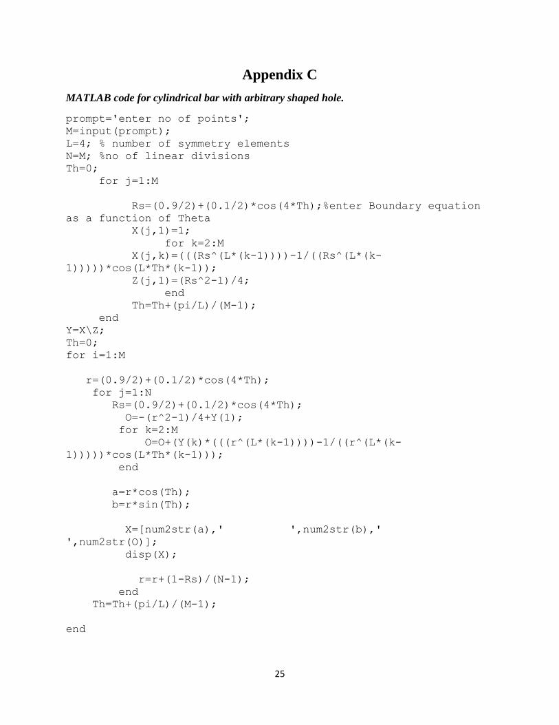
Appendix C
MATLAB code for cylindrical bar with arbitrary shaped hole.