® Section 61180019L1-5A Issue 1, May 2004 CLEI Code: VAM5500F_ _ 61180019L1-5A 1 Trademarks: Any brand names and product names included in this document are trademarks, registered trademarks, or trade names of their respective holders. Figure 1. Total Access 1500 19-Inch Chassis CONTENTS 1. General .................................................................... 1 2. Installation ............................................................... 3 3. Maintenance .......................................................... 13 4. Specifications ........................................................ 13 5. Warranty and Customer Service ........................... 14 FIGURES Figure 1. Total Access 1500 19-Inch Chassis ............. 1 Figure 2. Flush-Mount Bracket Orientation ................ 4 Figure 3. Mid-Mount Bracket Orientation .................. 4 Figure 4. Power and Ground Connectors .................... 5 Figure 5. Backplane and Pinouts ................................. 6 Figure 6. Ring Generator Terminal ............................. 7 Figure 7. Daisy-Chained Composite Clock Wiring .... 8 Figure 8. Alarm Contacts .......................................... 10 Figure 9. RS-485 Wiring ........................................... 12 TABLES Table 1. Compliance Codes ........................................ 2 Table 2. Specifications .............................................. 13 1. GENERAL This practice is an installation and maintenance guide for the ADTRAN Total Access 1500 ® 19-Inch Chassis (P/N 1180019L1). Figure 1 illustrates the a populated 19-Inch Chassis. Revision History This is the initial issue of this practice. Future changes to this documentation will be explained in this subsection. Features The basic features of the Total Access 1500 19-Inch Chassis include the following: • Rackmount design • Scalable network connectivity • 1-5 T1 capacity (4 T1s and a Protect T1 for TR-08 applications utilizing a Quad LIU) • Three common modules: – Power Supply/Ring Generator Unit (PSU/RGU) – System Controller Unit (SCU) – Line Interface Unit (LIU) • T1 Network Interface • 18 slots for combination of voice and data services • Variety of access module units • Network management capabilities (TL1, SNMP) • Multiple configuration arrangements • TR-08 compatible (Modes 1, 2, and 3) • Supports Mechanized Loop Testing (MLT) • NRTL Safety Listed and FCC compliant • Meets NEBS Level 3 requirements Description The Total Access 1500 19-Inch Chassis is designed to meet a variety of operating configurations and services, such as POTS and Special Services. The Total Access 1500 19-Inch Chassis is intended for use in Central Office (CO), Remote Terminal (RT), and customer premises applications. The Total Access 1500 System is comprised of the chassis, common modules, and access modules. Total Access 1500 19-Inch Chassis Installation and Maintenance Practice PSU-A PSU-A PSU-B SCU 1 2 3 4 5 6 7 8 9 10 11 12 14 13 15 16 17 18 LIU-B 1180008L2 POTS RT POTS RT POTS RT POTS RT POTS RT POTS RT POTS RT POTS RT POTS RT POTS RT POTS RT POTS RT POTS RT POTS RT POTS RT POTS RT POTS RT POTS RT 1180007L3 1180007L3
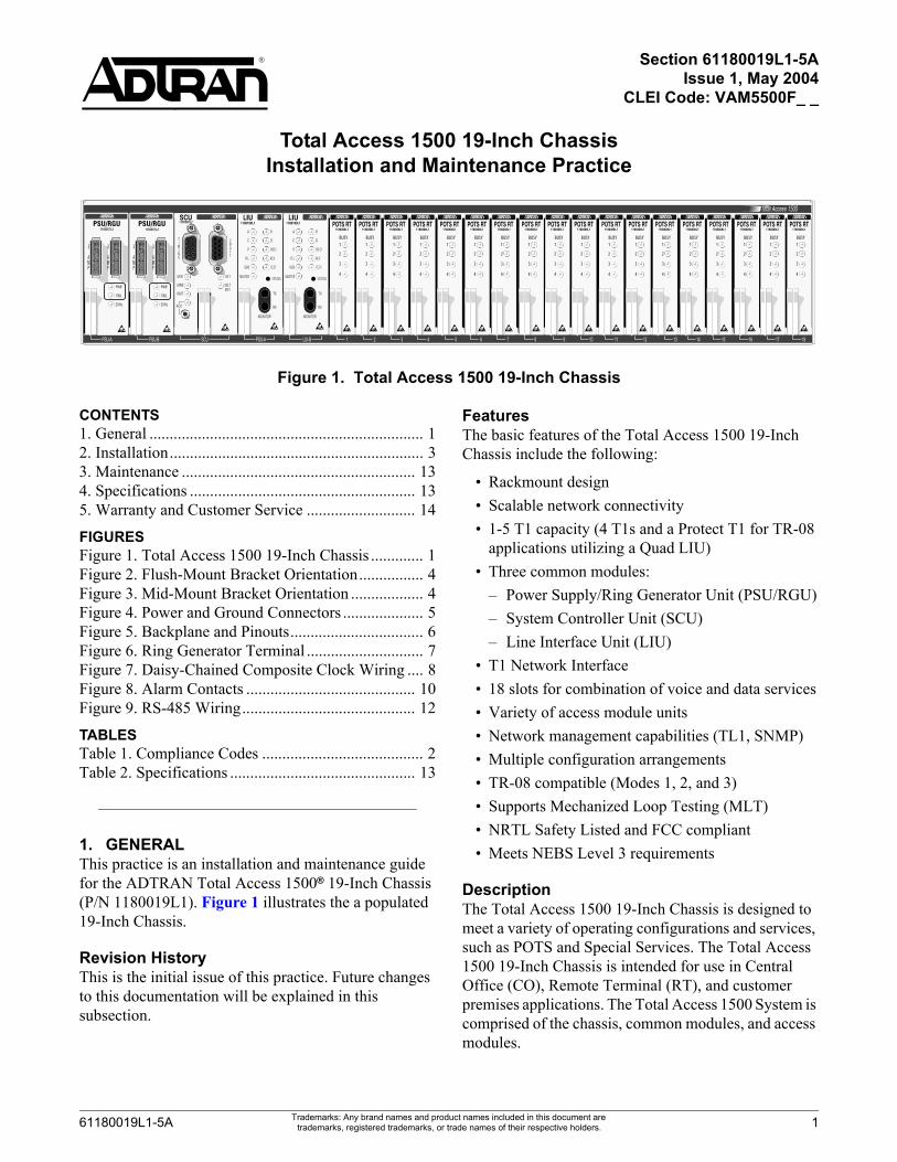
1. GENERALThis practice is an installation and maintenance guide for the ADTRAN Total Access 1500® 19-Inch Chassis (P/N 1180019L1). Figure 1 illustrates the a populated 19-Inch Chassis.
Revision HistoryThis is the initial issue of this practice. Future changes to this documentation will be explained in this subsection.
61180019L1-5A Trademarks: Any brand names and produtrademarks, registered trademarks, or t
FeaturesThe basic features of the Total Access 1500 19-Inch Chassis include the following:
• Rackmount design• Scalable network connectivity • 1-5 T1 capacity (4 T1s and a Protect T1 for TR-08
applications utilizing a Quad LIU)• Three common modules:
– Power Supply/Ring Generator Unit (PSU/RGU)– System Controller Unit (SCU)– Line Interface Unit (LIU)
• T1 Network Interface• 18 slots for combination of voice and data services• Variety of access module units• Network management capabilities (TL1, SNMP)• Multiple configuration arrangements• TR-08 compatible (Modes 1, 2, and 3)• Supports Mechanized Loop Testing (MLT)• NRTL Safety Listed and FCC compliant• Meets NEBS Level 3 requirements
DescriptionThe Total Access 1500 19-Inch Chassis is designed to meet a variety of operating configurations and services, such as POTS and Special Services. The Total Access 1500 19-Inch Chassis is intended for use in Central Office (CO), Remote Terminal (RT), and customer premises applications. The Total Access 1500 System is comprised of the chassis, common modules, and access modules.
Total Access 1500 19-Inch ChassisInstallation and Maintenance Practice
1ct names included in this document are rade names of their respective holders.
The Total Access 1500 19-Inch Chassis is 19-inches wide by 3.50-inches high by 10.75 inches deep, and the chassis mounts in a standard 19 or 23-inch wide rack. The Total Access 1500 19-Inch Chassis and is made of heavy gauge metal.
Common ModulesThe common modules supported by the Total Access 1500 19-Inch Chassis are described below.
PSU/RGUThe Power Supply Unit/Ring Generator Unit (PSU/RGU) receives –48 VDC from an external source to provide all necessary voltages required by the other common modules and channel units. Two PSU/RGUs may be installed to provide fully redundant operation. Through switch mode operation, either PSU converts the incoming –48 VDC to regulated +3.3 VDC, +5 VDC, and unregulated –7.5 VDC, –24 VDC, and –48 VDC for distribution to the other modules. Ring voltage circuitry within the PSU generates 105 Vrms nominal, 20 Hz ring voltage for distribution to the channel bank’s voice modules. Ring voltage is disabled by removing the 5-amp GMT front panel fuse labeled 20Hz. The PSU/RGU does not require provisioning prior to insertion into the channel bank.
CAUTIONThe Total Access 1500 19-Inch Chassisrequires the use of the List 3 and List 4 PSUs(P/N 1180007L3, 1180007L4).
SCUThe System Controller Unit (SCU) provides network management capability for the channel bank. The SCU is used to provision, test, and determine status for any module in the channel bank. It is also available in Central Office Terminal (COT) and Remote Terminal (RT) versions with Mechanized Loop Testing. The front panel has craft interface, test equipment timing output, alarm and status indicators, plus an Alarm Cut-Off (ACO) switch.
LIUThe Line Interface Unit (LIU) terminates up to four T1 lines, with a separate T1 that is included for protection switching with the Quad LIU or two T1 lines with the Dual LIU. The LIU generates control signals and clocks used by the channel units, and controls both manual and remotely initiated T1 loopbacks. It detects alarm condi-tions and reports the alarm status to the SCU.
2 Issue 1, M
The LIU front panel has a dual bantam jack for T1 test access, status LEDs, and a STATUS pushbutton.
WARNINGIf two (redundant mode) List 2 Quad LIUs (P/N 1180109L2) are utilized in the TotalAccess 1500 19-Inch Chassis, the T1 (DSX-1)interfaces must not be metallically connectedto interfaces that connect to the Outside Plantor its wiring. These interfaces are designed foruse as intra-building interfaces only. Theaddition of Primary Protectors is not sufficientprotection in order to connect these interfacesmetallically to OSP wiring.
It is permissible to connect the T1 (DS-1)interface metallically to the OSP if only oneLIU (non-redundant mode) is to be used at anytime in the Total Access 1500 19-Inch Chassis.
Access ModulesThe Total Access 1500 System incorporates a complete array of local loop access technologies into an integrated intelligence system. Most access modules occupy one slot in the Total Access 1500 19-Inch Chassis.
The access modules supported by Total Access 1500 System are listed in the Total Access 1500 System Manual (P/N 61180001L1-1). Refer to individual the Installation and Maintenance Practices and Job Aids for detailed information on installation, testing, operation, maintenance, and troubleshooting.
ComplianceTable 1 shows the compliance codes for the Total Access 1500 19-Inch Chassis. The 19-Inch Chassis is NRTL listed to the applicable UL standards. The 19-Inch Chassis is to be installed in a restricted access location and in a Type “B” or “E” enclosure only.
Table 1. Compliance Codes
Code Input Output
Power Code (PC) F C
Telecommunication Code (TC) X X
Installation Code (IC) B –
ay 2004 61180019L1-5A
This device complies with Part 15 of the FCC rules. Operation is subject to the following two conditions:
1. This device may not cause harmful interference.2. This device must accept any interference received,
including interference that may cause undesired operation.
Changes or modifications not expressly approved by ADTRAN could void the user’s authority to operate this equipment.
2. INSTALLATION
After unpacking the Total Access 1500 19-Inch Chassis, inspect it for damage. If damage has occurred, file a claim with the carrier, then contact ADTRAN Customer Service. Refer to the Warranty and Customer Service section for further information. If possible, keep the original shipping container for returning the 19-Inch Chassis for repair or for verification of shipping damage.
NOTEThis product is intended for installation inrestricted access locations only.
CAUTIONElectronic modules can be damaged by ESD.When handling modules, wear an antistaticdischarge wrist strap to prevent damage toelectronic components. Place modules inantistatic packing material when transportingor storing. When working on modules, alwaysplace them on an approved antistatic mat that iselectrically grounded.
WARNINGTo prevent electrical shock, do not installequipment in a wet location or during alightning storm.
C A U T I O N ! SUBJECT TO ELECTROSTATIC DAMAGE
OR DECREASE IN RELIABILITY.
HANDLING PRECAUTIONS REQUIRED.
61180019L1-5A Issue 1, M
Tools RequiredThe required tools for the Total Access 1500 19-Inch Chassis installation are as follows:
• Wire-wrap tool• #2 phillips-head screwdriver• #1 phillips-head screwdriver• Straight-slot-head screwdriver• Multimeter• Crimping tool for power lugs• Wire strippers• Side cutters• 3/16-inch wrench
Material that should be on hand includes the following:
• Four screws for mounting each Total Access 1500 19-Inch Chassis to the rack
• Shielded 2-wire, twisted pair cross-connect wire with drain, such as AT&T P7 wire
• Insulated wire for power connections• Insulated wire for frame ground• Lugs for the power wire and Frame Ground
connection
Unpack and Inspect the ChassisEach Total Access 1500 19-Inch Chassis is shipped in its own cardboard shipping carton unless it was ordered as a fully racked cabinet or wall mount system. Open each carton carefully and avoid cutting too deep into the carton with sharp objects.
Mounting the ChassisThe Total Access 1500 19-Inch Chassis can be flush-mounted or mid-mounted.
Mounting Bracket Orientation The Total Access 1500 19-Inch Chassis comes with mounting brackets that can be mounted with the flanges facing forward or backward in two different locations on the chassis sides. This allows the chassis to be flush-mounted or mid-mounted. Attaching the mounting brackets to the chassis requires three screws on each side that are supplied with the unit.
The mounting brackets can be used for 19 or 23-inch rack applications:
• The narrow side should be screwed to the chassis for a 23-inch rack.
• The wide side should be screwed to the chassis for a 19-inch rack
ay 2004 3
The recommended ways to mount the chassis are as follows:
• Flush-mount: To flush-mount a Total Access 1500 19-Inch Chassis in the rack, use a #2 phillips-head screwdriver and attach the mounting brackets (see Figure 2) with the flanges containing the slotted rack-mounting holes facing the front of the Total Access 1500 19-Inch Chassis. The mounting brack-ets should be attached using the set of mounting bracket holes closest to the rear of the Total Access 1500 19-Inch Chassis.
Figure 2. Flush-Mount Bracket Orientation
• Mid-mount: To mid-mount a Total Access 1500 19-Inch Chassis in the rack, use a #2 phillips-head screwdriver and attach the mounting brackets (see Figure 3) with the flanges containing the slotted rack-mounting holes facing the rear of the Total Access 1500 19-Inch Chassis. The mounting brack-ets should be attached using the set of mounting bracket holes closest to the front of the Total Access 1500 19-Inch Chassis.
Figure 3. Mid-Mount Bracket Orientation
18
17
16
15
18
17
16
15
4 Issue 1, M
Installing the ChassisAfter attaching the mounting brackets to the Total Access 1500 19-Inch Chassis sides, use the appropriate screws for the CO rack type and mount the chassis in the rack as follows:
1. Flush-mount: For flush-mount systems, the Total Access 1500 19-Inch Chassis must be mounted from the rear of the rack, with mounting bracket flanges facing rearward.
2. Mid-mount: For mid-mount systems, the Total Access 1500 19-Inch Chassis must be mounted from the front of the rack, with the mounting bracket flanges facing forward.
NOTEOther orientations will require either mountingfrom the front or rear, and depend on the racktype installed in the CO and the standardoperating procedures established by the CO.
Once the orientation of the chassis has been determined, use the four appropriate screws for the CO rack and an appropriate screwdriver and secure the Total Access 1500 19-Inch Chassis in place on the rack.
ConnectionsInterconnections between the common modules and channel units are accomplished through the backplane PCB. All external connections to the Total Access 1500 19-Inch Chassis are through connectors and wire-wrap headers located on the backplane.
NOTEWhen connecting power and ground wiring, besure to follow all local, national, and companycodes.
CAUTIONPer GR-1089-CORE October 2002, section 9,this system is designed and intended only forinstallation in a DC-C (common) Bonding andGrounding System. It is not intended ordesigned for installation in a DC-I (isolated)Bonding and Grounding system.
ay 2004 61180019L1-5A
All permanent connections to the Total Access 1500 19-Inch Chassis are made on the backplane. Figure 4 is a detailed diagram of the power and ground connectors, and Figure 5 is an illustration of the backplane and pinouts.
Figure 4. Power and Ground Connectors
Frame Ground ConnectionThe frame ground terminal, located on the upper right corner of the backplane (see Figure 4 and Figure 5), should be connected using appropriately sized wire. Use a wire gauge that is at least the same gauge as the power wiring.
To make the frame ground connection to the Total Access 1500 19-Inch Chassis, perform the following steps:
1. Using the crimping tool, connect an appropriate lug to each end of the appropriately sized wire.
2. Connect the ground wire from Total Access 1500 19-Inch Chassis ground terminal on TB1 to the equipment rack grounding screw.
3. Tighten the ground connection securely with a straight-slot screwdriver.
Test Frame Ground ConnectionTo ensure a good ground, use a multimeter to check continuity between the frame grounding lug and the rack grounding strap at the top of the rack. Using an ohmmeter set to its the lowest resistance range, place one lead on the rack’s ground strap and the other lead on the Total Access 1500 19-Inch Chassis ground terminal on TB1. The reading should be 1 or 2 ohms. Greater readings should be investigated.
TB1Pin Number Description
� ���� �� �
� ���� �� �
���� �� ���
� ���� �� ���
� ����� ������
TB1
IN IN
RTN
RTN
IN RTN
-48V PRI
IN RTN
-48V SEC
61180019L1-5A Issue 1, M
Power Connection
NOTEConnect to a reliably grounded –48 VDCsource, which is electrically isolated from theAC source.
NOTEA readily accessible disconnect device, such asa rackmount fuse and alarm panel that issuitably approved and rated, should be incor-porated in the fixed wiring.
Power connections use a block, labeled TB1, located on the upper right side of the backplane (see Figure 4 and Figure 5). The terminals are on 0.375 inch centers and allow for wire gauges up to 12 AWG. The frame ground terminal routes to mechanical contact points and provides an electrical connection to the chassis metalwork. The power bus and frame ground route to all the modules in the chassis.
The number of Total Access 1500 19-Inch Chassis that can be placed in a 7-foot CO rack depends on the type of service deployed and the number of access modules in the chassis.
After connecting and checking the ground to the Total Access 1500 19-Inch Chassis, connect power to the chassis. Check to make sure the power source is providing the correct power and polarity to the Total Access 1500 19-Inch Chassis. The following steps provide instructions on how to connect power to the chassis.
1. Determine which fuse pairs are to supply power to the Total Access 1500 19-Inch Chassis.
2. Remove the fuses from the A and B slots for the pair.
3. The power terminal is labeled TB1. Cut four lengths of appropriately sized wire to reach from the terminals on the fuse and alarm panel to the power terminals on the Total Access 1500 19-Inch Chassis.
4. Using the crimping tool, connect an appropriate lug to each end of the wires.
ay 2004 5
Figure 5. Backplane and Pinouts
RS
-232
(J3
4)
Pin
Nu
mb
er
D
escr
ipti
on
1
Fr
ame
Gro
und
2
T
xD
3
RxD
4
R
TS
5
C
TS
6
D
SR
7
G
ND
8
D
CD
9
N
o C
onne
ct
10
No
Con
nect
1
1
N
o C
onne
ct
1
2
N
o C
onne
ct
13
No
Con
nect
1
4
N
o C
onne
ct
15
TX
C
16
No
Con
nect
1
7
R
XC
1
8
N
o C
onne
ct
19
No
Con
nect
2
0
D
TR
2
1
N
o C
onne
ct
2
2
N
o C
onne
ct
23
No
Con
nect
2
4
E
XT
C
25
No
Con
nect
E
ther
net
(J3
3)P
in N
um
ber
Des
crip
tio
n
1
ET
HR
TX
+
2
ET
HR
TX
-
3
ET
HR
RX
+
4
X
5
X
6
ET
HR
RX
-
7
X
8
X
Ala
rm (
P13
)P
in N
um
ber
D
escr
ipti
on
1
AU
X1
A
2
A
UX
1 B
3
AU
X2
A
4
A
UX
2 B
5
V
MJ(
T1A
)NO
6
V
MJ(
T1A
)CO
M
7
VM
J(T
1A)N
C
8
VM
N(T
1B)N
O
9
VM
N(T
1B)C
OM
1
0
VM
N(T
1B)N
C
11
A
MJ(
T1C
)NO
1
2
AM
J(T
1C)C
OM
1
3
AM
J(T
1C)N
C
14
A
MN
(T1D
)NO
1
5
AM
N(T
1D)C
OM
1
6
AM
N(T
1D)N
C
17
A
UX
(BA
NK
)NO
1
8
AU
X(B
AN
K)N
O
19
A
UX
(BA
NK
)NC
2
0
PW
RC
OM
2
1
PW
RN
O
Co
mp
osi
te C
lock
(P
14)
Pin
Nu
mb
er
Des
crip
tio
n
1
CLK
INS
+
2
CLK
INS
-
3
Fra
me
Gro
und
4
C
LKO
UT
S+
5
CLK
OU
TS
-
6
Fra
me
Gro
und
7
C
LKIN
P+
8
CLK
INP
-
9
Fra
me
Gro
und
1
0
C
LKO
UT
P+
1
1
C
LKO
UT
P-
1
2
F
ram
e G
roun
d
TB
1P
in N
um
ber
D
escr
ipti
on
1
-4
8V IN
SE
C
2
-4
8V R
TN
SE
C
3
-48V
IN P
RI
4
-48V
RT
N P
RI
5
Fra
me
Gro
und
LO
CC
K/R
S-4
85 (
P12
)P
in N
um
ber
D
escr
ipti
on
1
L
OC
CK
+
2
L
OC
CK
-
3
RS
-485
A
4
RS
-485
B
5
Fra
me
Gro
und
TB
2P
in N
um
ber
Des
crip
tio
n
1
F
ram
e G
roun
d
2
2
0 H
Z R
TN
3
20
HZ
EX
T
Met
allic
Lo
op
Tes
t B
ypas
s P
air
(P6)
P
in N
um
ber
D
escr
ipti
on
1
B
YPA
SS
TIP
2
B
YPA
SS
RIN
G
3
INH
IBIT
4
F
ram
e G
roun
d
T1
Co
nn
ecti
on
sP
in N
um
ber
P7
– P
rote
ctP
8 –
T1
DP
9 –
T1
CP
10 –
T1
BP
11 –
T1
A
1T
Pro
tect
T D
T C
T B
T A
2R
Pro
tect
R D
R C
R B
R A
3T
1 P
rote
ctT
1T
1 C
T1
BT
1 A
4R
1 P
rote
ctR
1 D
R1
CR
1 B
R1
A
5
Fram
eFr
ame
Fram
eFr
ame
Fram
eG
roun
dG
roun
dG
roun
dG
roun
dG
roun
d
T/R
= T
rans
mit
= O
UT
T1/
R1
= R
ecei
ve =
IN
PGTC
Am
phen
ol C
onne
ctor
P5Pi
nDe
scrip
tion
Pin
Desc
ri ptio
n1
MLT
RA
26M
LT T
A2
MLT
RB
27M
LT T
B3
MLT
RC
28M
LT T
C4
MLT
RD
29M
LT T
D5
SLV
B30
SLV
A6
SLV
D31
SLV
C7
OH
B32
OH
A8
OH
D33
OH
C9
PRO
C B
34PR
OC
A10
PRO
C D
35PR
OC
C11
LOCK
B36
LOC
K A
12LO
CK D
37LO
CK
C13
SM
AS
RA
38S
MA
S TA
14S
MA
S R
B39
SM
AS
TB15
SM
AS
RC
40S
MA
S TC
16S
MA
S R
D41
SM
AS
TD17
TMA
J42
TSTA
LM18
No
Conn
ect
43N
o Co
nnec
t19
No
Conn
ect
44N
o Co
nnec
t20
No
Conn
ect
45N
o Co
nnec
t21
No
Conn
ect
46N
o Co
nnec
t22
SEZB
Y47
SEIZ
E23
No
Conn
ect
48N
o Co
nnec
t24
No
Conn
ect
49N
o Co
nnec
t25
No
Conn
ect
50N
o Co
nnec
t
Cust
omer
Am
phen
ol C
onne
ctor
sP1
P2P3
Pin
Slot
/Por
tSl
ot/P
ort
Slot
/Por
t26
/1 (T
/R)
1/1
7/1
13/1
27/2
(T/R
)1/
27/
213
/228
/3 (T
/R)
1/3
7/3
13/3
29/4
(T/R
)1/
47/
413
/430
/5 (T
/R)
2/1
8/1
14/1
31/6
(T/R
)2/
28/
214
/232
/7 (T
/R)
2/3
8/3
14/3
33/8
(T/R
)2/
48/
414
/434
/9 (T
/R)
3/1
9/1
15/1
35/1
0 (T
/R)
3/2
9/2
15/2
36/1
1 (T
/R)
3/3
9/3
15/3
37/1
2 (T
/R)
3/4
9/4
15/4
38/1
3 (T
/R)
4/1
10/1
16/1
39/1
4 (T
/R)
4/2
10/2
16/2
40/1
5 (T
/R)
4/3
10/3
16/3
41/1
6 (T
/R)
4/4
10/4
16/4
42/1
7 (T
/R)
5/1
11/1
17/1
43/1
8 (T
/R)
5/2
11/2
17/2
44/1
9 (T
/R)
5/3
11/3
17/3
45/2
0 (T
/R)
5/4
11/4
17/4
46/2
1 (T
/R)
6/1
12/1
18/1
47/2
2 (T
/R)
6/2
12/2
18/2
48/2
3 (T
/R)
6/3
12/3
18/3
49/2
4 (T
/R)
6/4
12/4
18/4
50/2
5No
Con
nect
21
J17
30
40
1 10
20
21
J1630
40
1 10
20
21
J15
30
40
1 10
20
21
J14
30
40
1 10
20
21
J13
30
40
1 10
20
21
J12
30
40
1 10
20
21
J11
30
40
1 10
20
21
J10
30
40
1 10
20
21
J9
30
40
1 10
20
21
J8
30
40
1 10
20
21
J7
30
40
1 10
20
21
J6
30
40
1 10
20
21
J5
J34
MGMT
30
40
1 10
20
21
J4
30
40
1 10
20
21
J3
30
40
1 10
20
21
J2
30
40
1 10
20
21
J1
30
40
1 10
20
21
J32 30
40
1
10
20
21
J30
30
40
1
1
10
20
J27
IN
RTN
IN
RTN
30
40
10 20
J26 30
40
10
20
21
J25 30
40
1
10
20
EDCBA
1
10
20
EDCBA
10
20
24
24
E
D
C
B
A
10
20
E
D
C
B
A
21
1
P18P12
P14C
P14B
P14A
P13
A
TR
T1R1
1
1P11
51
P10
51
P9
51
P8
51
P7
5
J31
J29
J28
BYPASS
E-N
ET
B
TR
T1R1
C
TR
T1R1
D
TR
T1R1
P
TR
T1R1
TR
I
P6
D2
D1
5
TB
3TB2
SMAS
MLT
-48V
SEC
-48V
SEC
MLT
T1/R1
P2
PAIR2
E/SG
P3
PAIR3
M/SB
PAIR4
P4
PGTC
P5
I N R T N
RN1
RN2
SW1
SW3
SW2
OUT
CLKTERMS
INOUT
CLKTERMP
RS485
INOU
T
ON
ON
ON
SLOTS
13-18
SLOTS
7-12
SLOTS
1-6
PGTC
WARNING
20HZFUSE
MUST
BEREM
OVEDBEFORE
REARCO
VER
Aux
1A
B Clk
inS
ec
+
-C
lk o
utS
ec
+
-
Aux
2A
B
Vis
Maj
(T1A
)N
O
C
NC
Clk
inP
ri
+
-C
lk o
utP
ri
+
-A
ux3
A
ux4
Vis
Min
(T1B
)N
O
C
NC
Aud
Maj
(T1C
)N
O
C
NC
(T1D
)N
O
C
NC
Aux
(Ban
k)N
O
C
NC
PW
R
+
-Lo
cal
Clk
RS
485
A
B
A
BA
B
P14
CP
14B
P14
A
P18
P12
P13
Aux
1A
B Clk
inS
ec
+
-C
lk o
utS
ec
+
-
Aux
2A
B
Vis
Maj
(T1A
)N
O
C
NC
Clk
inP
ri
+
-C
lk o
utP
ri
+
-A
ux3
A
ux4
(T1B
)N
O
C
NC
(T1C
)N
O
C
NC
Aud
Min
(T1D
)N
O
C
NC
Aux
(Ban
k)N
O
C
NC
CO
MP
WR
NO
+
-Lo
cal
Clk
RS
485
A
B
A
BA
B
P14
CP
14B
P14
A
P18
P12
P13
6 Issue 1, May 2004 61180019L1-5A
5. Using a screwdriver appropriate for the fuse and alarm panel terminals, and a straight slot or phillips screwdriver for the Total Access 1500 19-Inch Chassis power terminal, connect the ends of one wire between the “A” CO –48 VDC supply and the –48V PRI IN terminal on the Total Access 1500 19-Inch Chassis backplane.
6. Connect three more power wires, connecting the “A” CO –48 VDC return with –48V PRI RTN; “B” CO –48 VDC supply with –48V SEC IN; and “B” CO –48 VDC RTN with –48V SEC RTN.
Apply Power and Check VoltageBefore proceeding further, ensure that power has been correctly applied to the Total Access 1500 19-Inch Chassis. The proper voltage to the Total Access 1500 19-Inch Chassis is –48 VDC, with an operating range of –42 VDC to –56 VDC.
WARNINGInstalling fuses in the fuse alarm panel at thisstage will provide power to the Total Access1500 19-Inch Chassis. There will be power topins on the backplane and inside the TotalAccess 1500 19-Inch Chassis. Exercise cautionto avoid electric shock.
NOTEThe Total Access 1500 19-Inch Chassis maybe powered by multiple power sources.Disconnect all sources prior to servicing.
NOTEThe branch circuit over-current protectionshall be a fuse or circuit breaker rated for amaximum of –48 VDC @ 5.0 A. Include theappropriate input current rating for theproduct.
1. Install appropriate fuses (5 amp max) in the slots in the fuse and alarm panel that services the Total Access 1500 19-Inch Chassis.
2. Using a voltmeter, place the common (normally black) lead on the TB1 –48V PRI RTN terminal and the DC volts (normally red) lead on the TB1 –48V PRI IN terminal. The reading should be in the
61180019L1-5A Issue 1, M
operating range of –42 VDC to –56 VDC, with a nominal value of –48 VDC. Note the “negative” polarity.
3. Using a voltmeter, test the connection using the TB1 –48V SEC RTN terminal and the TB1 –48V SEC IN terminal.
4. Remove the fuses from the fuse and alarm panel slots that provide power to the Total Access 1500 19-Inch Chassis.
Ring Generator The Total Access 1500 System operates with either an internal or external ring generator. For external ring generator applications, TB2 (see Figure 6) provides terminal connections for ringing voltage, ringing return, and frame ground.
Figure 6. Ring Generator Terminal
Composite Clock ConnectionsAn external composite clock input is required in the COT when deploying digital services from the Total Access 1500 System. The following steps provide instruction on how to connect primary and secondary external composite clock signals to a single Total Access 1500 19-Inch Chassis.
1. Determine the “+”, “–” and drain or ground wires from the CO clock source.
2. Using wire strippers, strip 1 to 1-1/2 inches of the insulation from the end of the clock source twisted pair, shielded, drop wire.
3. Using the wire-wrap tool, wire wrap the “+” wire from the clock source to the pin marked + on connector P14, Clk in Pri.
4. Wire wrap the “–” wire from the clock source to the pin marked – on connector P14, Clk in Pri.
5. Wire wrap the drain or shield wire from the clock source to the pin marked as ground on connector P14, Clk in Pri.
TB2
20HZ
RTN
1
3
ay 2004 7
6. Tie the clock source wire neatly to the frame.7. Set SW3 to the IN position (SW3 is the center
switch in the three switch cluster located to the right of P14).
8. Repeat steps 1 through 6 for secondary clock to connector P14, Clk in Sec (optional).
8 Issue 1, M
9. Set SW1 to the IN position (SW1 is the left-most switch in the three switch cluster located to the right of P14).
Figure 7 illustrates the connections to a Total Access 1500 19-Inch Chassis utilizing external redundant timing.
Figure 7. Daisy-Chained Composite Clock Wiring
Clk inSec
+ -Clk out
Sec
+ -Clk in
Pri
+ -Clk out
Pri
+ -Aux3 Aux4
+ -Local Clk
RS485A B A B A B
P14CP14BP14A
P18P12
Clk inSec
+ -Clk out
Sec
+ -Clk in
Pri
+ -Clk out
Pri
+ -Aux3 Aux4
+ -Local Clk
RS485A B A B A B
P14CP14BP14A
P18P12
Clk inSec
+ -Clk out
Sec
+ -Clk in
Pri
+ -Clk out
Pri
+ -Aux3 Aux4
+ -Local Clk
RS485A B A B A B
P14CP14BP14A
P18P12
Clk inSec
+ -Clk out
Sec
+ -Clk in
Pri
+ -Clk out
Pri
+ -Aux3 Aux4
+ -Local Clk
RS485A B A B A B
P14CP14BP14A
P18P12
Clk inSec
+ -Clk out
Sec
+ -Clk in
Pri
+ -Clk out
Pri
+ -Aux3 Aux4
+ -Local Clk
RS485A B A B A B
P14CP14BP14A
P18P12
Clk inSec
+ -Clk out
Sec
+ -Clk in
Pri
+ -Clk out
Pri
+ -Aux3 Aux4
+ -Local Clk
RS485A B A B A B
P14CP14BP14A
P18P12
21
J17
30
40
1
10
20
21
J16
30
40
1
10
20
21
J15
30
40
1
10
20
21
J14
30
40
1
10
20
21
J13
30
40
1
10
20
21
J12
30
40
1
10
20
21
J11
30
40
1
10
20
21
J10
30
40
1
10
20
21
J9
30
40
1
10
20
21
J8
30
40
1
10
20
21
J7
30
40
1
10
20
21
J6
30
40
1
10
20
21
J5
J34
MGMT
30
40
1
10
20
21
J4
30
40
1
10
20
21
J3
30
40
1
10
20
21
J2
30
40
1
10
20
21
J1
30
40
1
10
20
21
J32
30
40
1
10
20
21
J30
30
40
1
1
10
20
J27
IN
RTN IN
RTN
30
40
10
20
J26
30
40
10
20
21
J25
30
40
1
10
20
E D C B A
1
10
20
E D C B A
10
20
24
24
E D C B A
10
20
E D C B A
211
P18
P12
P14C
P14B
P14A
P13
A
T R T1 R1
1
1 P11 5 1 P10 5 1 P9 5 1 P8 5 1 P7 5
J31
J29
J28
BY PA SS
E - N ET
B
T R T1 R1
C
T R T1 R1
D
T R T1 R1
P
T R T1 R1T R I
P6
D2
D1
5
TB
3 TB2
SMAS
MLT
-48V
SEC
-48V
SEC
MLT
T1 / R1P2 PAIR 2 E / SGP3 PAIR 3 M / SBPAIR 4P4 PGTC
P5
I
N
R
T
N
RN1
RN2
SW1 SW3 SW2
OUT
CLK TERMS
IN OUT
CLK TERMP RS485
IN OUT
O NO NO N
SLOTS 13-18
SLOTS
7-12
SLOTS
1-6 PGTC
W ARNING20 HZ FUSE MUST
BE REMOVED BEFORE
REAR COVER
Aux1A B
Clk inSec
+ -Clk out
Sec
+ -
Aux2A B
Vis Maj(T1A)
NO C NC
Clk inPri
+ -Clk out
Pri
+ -Aux3 Aux4
Vis Min(T1B)
NO C NC
Aud Maj(T1C)
NO C NC(T1D)
NO C NC
Aux(Bank)
NO C NCPWR
+ -Local Clk
RS485A B A B A B
P14CP14BP14A
P18P12
P13
Aux1A B
Clk inSec
+ -Clk out
Sec
+ -
Aux2A B
Vis Maj(T1A)
NO C NC
Clk inPri
+ -Clk out
Pri
+ -Aux3 Aux4
(T1B)NO C NC
(T1C)NO C NC
Aud Min(T1D)
NO C NC
Aux(Bank)
NO C NC COMPWRNO
+ -Local Clk
RS485A B A B A B
P14CP14BP14A
P18P12
P13
21
J17
30
40
1
10
20
21
J16
30
40
1
10
20
21
J15
30
40
1
10
20
21
J14
30
40
1
10
20
21
J13
30
40
1
10
20
21
J12
30
40
1
10
20
21
J11
30
40
1
10
20
21
J10
30
40
1
10
20
21
J9
30
40
1
10
20
21
J8
30
40
1
10
20
21
J7
30
40
1
10
20
21
J6
30
40
1
10
20
21
J5
J34
MGMT
30
40
1
10
20
21
J4
30
40
1
10
20
21
J3
30
40
1
10
20
21
J2
30
40
1
10
20
21
J1
30
40
1
10
20
21
J32
30
40
1
10
20
21
J30
30
40
1
1
10
20
J27
IN
RTN IN
RTN
30
40
10
20
J26
30
40
10
20
21
J25
30
40
1
10
20
E D C B A
1
10
20
E D C B A
10
20
24
24
E D C B A
10
20
E D C B A
211
P18
P12
P14C
P14B
P14A
P13
A
T R T1 R1
1
1 P11 5 1 P10 5 1 P9 5 1 P8 5 1 P7 5
J31
J29
J28
BY PA SS
E - N ET
B
T R T1 R1
C
T R T1 R1
D
T R T1 R1
P
T R T1 R1T R I
P6
D2
D1
5
TB
3 TB2
SMAS
MLT
-48V
SEC
-48V
SEC
MLT
T1 / R1P2 PAIR 2 E / SGP3 PAIR 3 M / SBPAIR 4P4 PGTC
P5
I
N
R
T
N
RN1
RN2
SW1 SW3 SW2
OUT
CLK TERMS
IN OUT
CLK TERMP RS485
IN OUT
O NO NO N
SLOTS 13-18
SLOTS
7-12
SLOTS
1-6 PGTC
W ARNING20 HZ FUSE MUST
BE REMOVED BEFORE
REAR COVER
Aux1A B
Clk inSec
+ -Clk out
Sec
+ -
Aux2A B
Vis Maj(T1A)
NO C NC
Clk inPri
+ -Clk out
Pri
+ -Aux3 Aux4
Vis Min(T1B)
NO C NC
Aud Maj(T1C)
NO C NC(T1D)
NO C NC
Aux(Bank)
NO C NCPWR
+ -Local Clk
RS485A B A B A B
P14CP14BP14A
P18P12
P13
Aux1A B
Clk inSec
+ -Clk out
Sec
+ -
Aux2A B
Vis Maj(T1A)
NO C NC
Clk inPri
+ -Clk out
Pri
+ -Aux3 Aux4
(T1B)NO C NC
(T1C)NO C NC
Aud Min(T1D)
NO C NC
Aux(Bank)
NO C NC COMPWRNO
+ -Local Clk
RS485A B A B A B
P14CP14BP14A
P18P12
P13
SW1 SW3
OUT
CLK TERMS
ININ OUT
CLK TERMP
O NO N
SW1 SW3
OUT
CLK TERMS
ININ OUT
CLK TERMP
O NO N
SW1 SW3
OUT
CLK TERMS
ININ OUT
CLK TERMP
O NO N
CO TIMING
+ – + –
ay 2004 61180019L1-5A
Up to 14 dual LIU systems or 28 single LIU systems may be daisy chained to a single output from the timing source. This results in a requirement for only one wire run from the timing source for an installation of up to 14 or 28 Total Access 1500 shelves. Use wire of the same type as the wire run from the CO clock source to the Total Access 1500 19-Inch Chassis. The following steps provide instructions for connecting multiple Total Access 1500 shelves to a single external timing source.
1. Determine the length of wire required to run from the first chassis, connector P14, to the second chas-sis, connector P14. Leave approximately 1 to 1-1/2 inches for wire wrapping.
2. Using wire strippers, strip approximately 1 to 1-1/2 inches from both ends of the wire run.
3. Using a wire-wrap tool, wire wrap the “+”, “–” and drain wires to the “+”, “–” and ground terminal pins of connector P14, Clk out Pri, on the top of the backplane.
4. Run the wire from P14 on the “source” chassis to connector P14, Clk in Pri, on the “receiving” chassis.
5. Wire wrap the “+”, “–” of the wire run to the “+”, “–” terminals of P14 on the “receiving” chassis.
6. Set SW3 on the “source” chassis to the IN position, and Set SW3 on the “receiving” chassis to the OUT position.
NOTEIn any daisy chain of Total Access 1500shelves using a single timing source, only thefirst chassis in the chain should have switchSW3 set to IN. All the remaining chassis in thechain should have SW3 set to OUT.
7. Repeat steps 1 through 6 for each Total Access 1500 shelf that is to be connected to the single CO timing source.
8. Repeat steps 1 through 7 for secondary clock.
NOTEIf connecting the secondary clock source, setSW1 to the SW3 settings.
Figure 7 illustrates a daisy-chained composite clock configuration.
61180019L1-5A Issue 1, M
Composite Clock OutputBecause some applications may require the Total Access 1500 System to provide source timing, an additional connection is provided on P12 labeled Local Clk (+, -) to provide a 64 kHz composite clock output. This output clock can be used as a timing source for up to 14 dual LIU systems or 28 single LIU systems.
Mechanized Loop Testing ConnectionsA four-lead (T, R, I, and drain) common test access bus is provided for mechanized loop test access to all customer loops, labeled P6 on the backplane. Instruc-tions for connecting the Total Access 1500 19-Inch Chassis for mechanized loop test access are as follows:
1. After locating the test loops and running them to the Total Access 1500 19-Inch Chassis, use wire strippers to strip approximately 1 to 1-1/2 inches from the test leads.
2. Using the wire-wrap tool, wire wrap the central office “T” and “R” leads to the Total Access 1500 19-Inch Chassis R and T pins, respectively, on terminal P6.
3. Wire wrap the inhibit wire of the cable to the pin labeled I on P6.
4. Wire wrap the drain wire of the cable to the pin labeled ground on P6.
5. Neatly tie down the test cable pair.
Alarm Output ConnectionsAlarm interpretation is dependent on how the Total Access 1500 System is configured. When the system is deployed in a single or dual T1 feed, the SCU should be provisioned for D4 Conventional Alarm Relay Mapping. The alarm outputs will be designated as follows:
• VIS MAJ (Visual Major)• VIS MIN (Visual Minor) • AUD MAJ (Audible Major) • AUD MIN (Audible Minor) • AUX (Auxiliary) • PWR
When deployed in a DLC configuration using a quad T1 feed, the SCU can be provisioned for T1 Mapping which provides the following alarm outputs:
In the T1 Mapping mode, the Total Access 1500 separately monitors the performance of each digroup (A, B, C and D) and the bank. The T1 Mapping mode assures that an alarm at the digroup level provides appropriate central office and remote information.
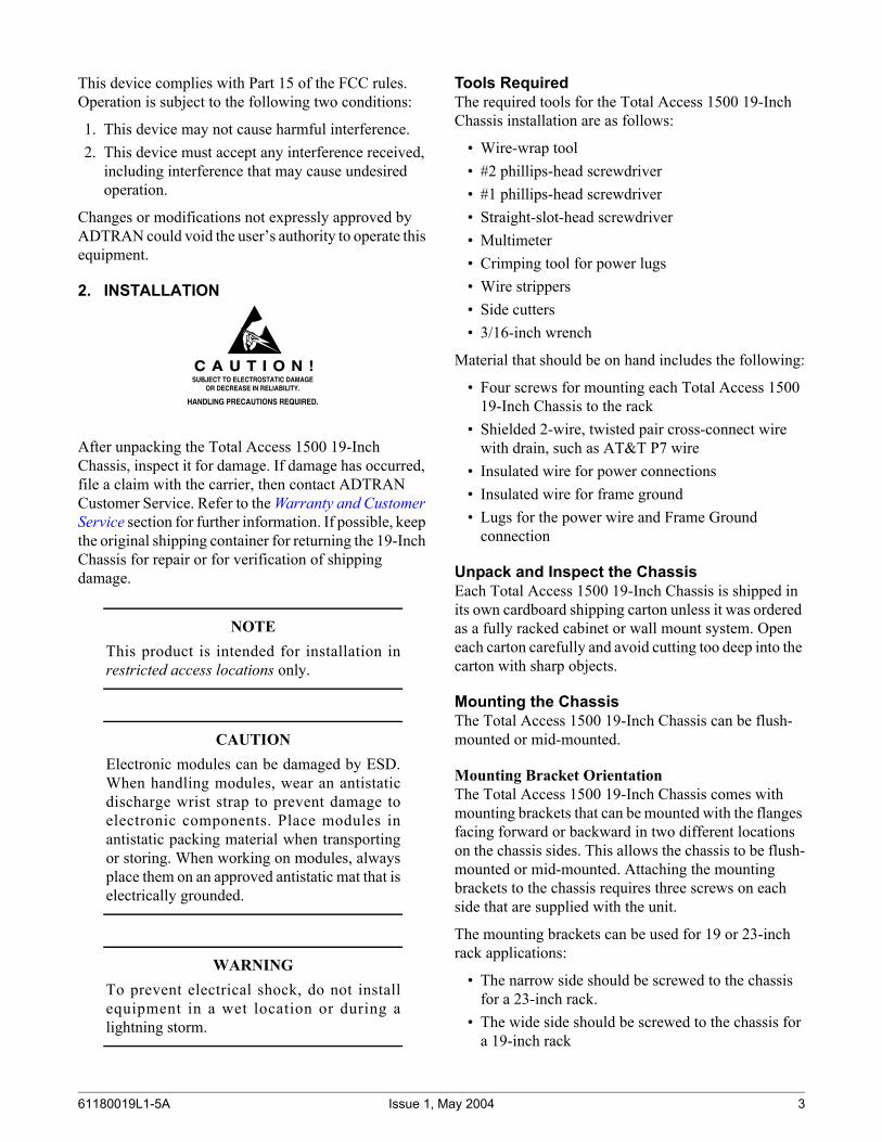
The Total Access 1500 19-Inch Chassis provides standard bank alarm outputs. Each of the alarms listed below consists of a three-pin wire-wrap header that connects to the SCU for alarm management. The SCU provides the necessary electronic circuits for a NO/COM/NC contact arrangement. The alarms are as follows:
The alarm configuration is selected as an SCU option through the VT100 craft interface.
Connecting Alarm OutputsDepending on the vendor equipment employed at the CO, wiring external alarms from the Total Access 1500 19-Inch Chassis will vary slightly. The important consideration is whether the external alarm equipment requires a Normally Open (NO) or Normally Closed (NC) circuit to pass an alarm. After determining what the CO equipment requires, connection can be made to the equipment from the Total Access 1500 19-Inch Chassis, see Figure 8 for the location of alarm contacts.
NOTEEach three-pin alarm header is wired the sameway for the specified alarm.
To connect alarm outputs to the Total Access 1500 19-Inch Chassis, perform the following steps:
1. Determine whether the external alarm reporting device uses a normally open or normally closed circuit for alarm relay.
2. Using standard telco cross-connect wire, determine and cut the length required to reach from the alarm headers to the alarm-reporting device.
3. Using wire strippers, strip 1 to 1-1/2 inches from both ends of the wire.
10 Issue 1, M
Figure 8. Alarm Contacts
4. Using a wire-wrap gun, wire wrap one strand to the center pin (common) of the Total Access alarm relay header, and the other strand to either the “NO” (normally open) or “NC” (normally closed) pin on the relay header.
5. Connect the two wires to the appropriate terminals on the external alarm relay device being used.
Connecting Miscellaneous Alarm InputsThere are four external alarm inputs that can be reported to the SCU on the Total Access 1500 19-Inch Chassis: Aux1 and Aux2 located on P13 and Aux3 and Aux4 located on P18. Terminal A expects –48 VDC if an alarm condition exists on the alarmed equipment. Terminal B supplies a –48 VDC source.
To connect an external alarm input to the Total Access 1500 19-Inch Chassis, perform the following steps:
1. Choose an alarm header set from P13 or P18 on the Total Access 1500 19-Inch Chassis backplane.
2. Using standard telco cross-connect wire, determine and cut the length required to reach from the alarmed piece of equipment to the chosen header.
3. Using wire strippers, strip 1 to 1-1/2 inches of insulation from both ends of the wire.
Alarm Outputs (P1 3 )Pin Number Description 1 AUX 1 A 2 AUX 1 B 3 AUX 2 A 4 AUX 2 B 5 Vis Maj (T1A) NO 6 Vis Maj (T1A) C 7 Vis Maj (T1A) NC 8 Vis Man (T1B) NO 9 Vis Man (T1B) C 10 Vis Man (T1B) NC 11 Aud Maj (T1C) NO 12 Aud Maj (T1C) C 13 Aud Maj (T1C) NC 14 Aud Min (T1D) NO 15 Aud Min (T1D) C 16 Aud Min (T1D) NC 17 AUX (BANK) NO 18 AUX (BANK) C 19 AUX (BANK) NC 20 PWR COM 21 PWR NO
Aux1A B
Aux2A B
Vis Maj(T1A)
NO C NC
Vis Min(T1B )
NO C NC
Aud Maj(T1C)
NO C NC(T1D)
NO C NC
Aux(Bank)
NO C NCPWR
P13
Aux1A B
Aux2A B
Vis Maj(
NO C NC(
NO C NC(
NO C NC
Aud Min(
NO C NC
Aux(B
NO C NC COMPWRNO
P13
ay 2004 61180019L1-5A
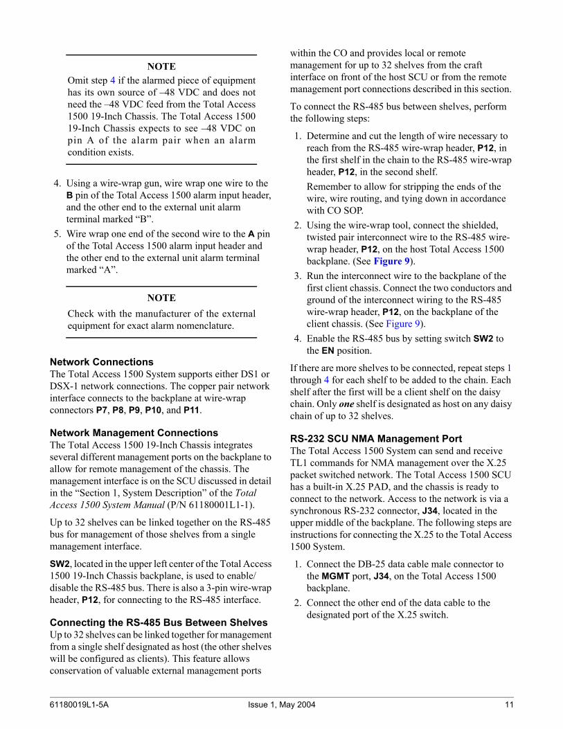
NOTEOmit step 4 if the alarmed piece of equipmenthas its own source of –48 VDC and does notneed the –48 VDC feed from the Total Access1500 19-Inch Chassis. The Total Access 150019-Inch Chassis expects to see –48 VDC onpin A of the alarm pair when an alarmcondition exists.
4. Using a wire-wrap gun, wire wrap one wire to the B pin of the Total Access 1500 alarm input header, and the other end to the external unit alarm terminal marked “B”.
5. Wire wrap one end of the second wire to the A pin of the Total Access 1500 alarm input header and the other end to the external unit alarm terminal marked “A”.
NOTECheck with the manufacturer of the externalequipment for exact alarm nomenclature.
Network ConnectionsThe Total Access 1500 System supports either DS1 or DSX-1 network connections. The copper pair network interface connects to the backplane at wire-wrap connectors P7, P8, P9, P10, and P11.
Network Management ConnectionsThe Total Access 1500 19-Inch Chassis integrates several different management ports on the backplane to allow for remote management of the chassis. The management interface is on the SCU discussed in detail in the “Section 1, System Description” of the Total Access 1500 System Manual (P/N 61180001L1-1).
Up to 32 shelves can be linked together on the RS-485 bus for management of those shelves from a single management interface.
SW2, located in the upper left center of the Total Access 1500 19-Inch Chassis backplane, is used to enable/disable the RS-485 bus. There is also a 3-pin wire-wrap header, P12, for connecting to the RS-485 interface.
Connecting the RS-485 Bus Between ShelvesUp to 32 shelves can be linked together for management from a single shelf designated as host (the other shelves will be configured as clients). This feature allows conservation of valuable external management ports
61180019L1-5A Issue 1, M
within the CO and provides local or remote management for up to 32 shelves from the craft interface on front of the host SCU or from the remote management port connections described in this section.
To connect the RS-485 bus between shelves, perform the following steps:
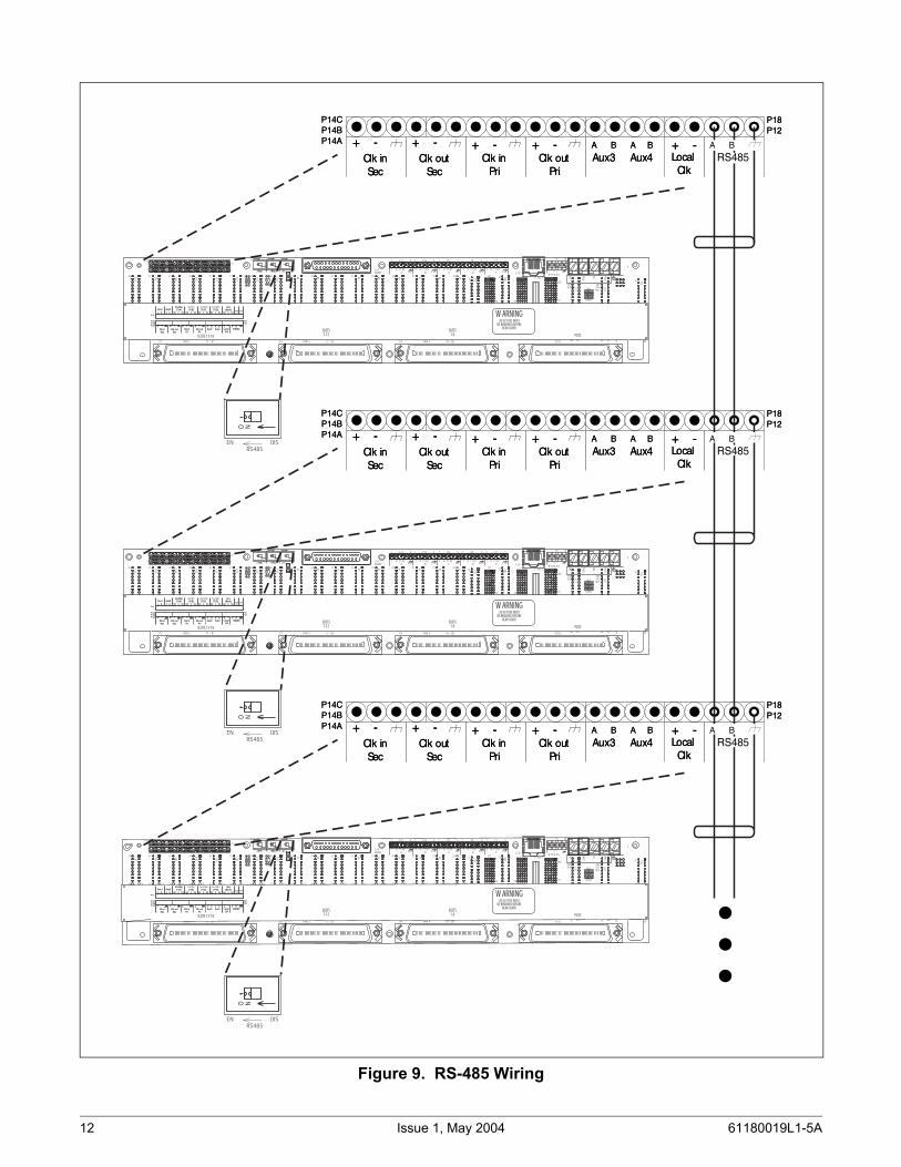
1. Determine and cut the length of wire necessary to reach from the RS-485 wire-wrap header, P12, in the first shelf in the chain to the RS-485 wire-wrap header, P12, in the second shelf. Remember to allow for stripping the ends of the wire, wire routing, and tying down in accordance with CO SOP.
2. Using the wire-wrap tool, connect the shielded, twisted pair interconnect wire to the RS-485 wire-wrap header, P12, on the host Total Access 1500 backplane. (See Figure 9).
3. Run the interconnect wire to the backplane of the first client chassis. Connect the two conductors and ground of the interconnect wiring to the RS-485 wire-wrap header, P12, on the backplane of the client chassis. (See Figure 9).
4. Enable the RS-485 bus by setting switch SW2 to the EN position.
If there are more shelves to be connected, repeat steps 1 through 4 for each shelf to be added to the chain. Each shelf after the first will be a client shelf on the daisy chain. Only one shelf is designated as host on any daisy chain of up to 32 shelves.
RS-232 SCU NMA Management PortThe Total Access 1500 System can send and receive TL1 commands for NMA management over the X.25 packet switched network. The Total Access 1500 SCU has a built-in X.25 PAD, and the chassis is ready to connect to the network. Access to the network is via a synchronous RS-232 connector, J34, located in the upper middle of the backplane. The following steps are instructions for connecting the X.25 to the Total Access 1500 System.
1. Connect the DB-25 data cable male connector to the MGMT port, J34, on the Total Access 1500 backplane.
2. Connect the other end of the data cable to the designated port of the X.25 switch.
ay 2004 11
Figure 9. RS-485 Wiring
Clk inSec
+ -Clk out
Sec
+ -Clk in
Pri
+ -Clk out
Pri
+ -Aux3 Aux4
+ -Local Clk
RS485A B A B A B
P14CP14BP14A
P18P12
Clk inSec
+ -Clk out
Sec
+ -Clk in
Pri
+ -Clk out
Pri
+ -Aux3 Aux4
+ -Local Clk
A B A B
P14CP14BP14A
P18P12
Clk inSec
+ -Clk out
Sec
+ -Clk in
Pri
+ -Clk out
Pri
+ -Aux3 Aux4
+ -Local Clk
RS485A B A B A B
P14CP14BP14A
P18P12
Clk inSec
+ -Clk out
Sec
+ -Clk in
Pri
+ -Clk out
Pri
+ -Aux3 Aux4
+ -Local Clk
A B A B
P14CP14BP14A
P18P12
Clk inSec
+ -Clk out
Sec
+ -Clk in
Pri
+ -Clk out
Pri
+ -Aux3 Aux4
+ -Local Clk
RS485A B A B A B
P14CP14BP14A
P18P12
Clk inSec
+ -Clk out
Sec
+ -Clk in
Pri
+ -Clk out
Pri
+ -Aux3 Aux4
+ -Local Clk
A B A B
P14CP14BP14A
P18P12
21
J17
30
40
1
10
20
21
J16
30
40
1
10
20
21
J15
30
40
1
10
20
21
J14
30
40
1
10
20
21
J13
30
40
1
10
20
21
J12
30
40
1
10
20
21
J11
30
40
1
10
20
21
J10
30
40
1
10
20
21
J9
30
40
1
10
20
21
J8
30
40
1
10
20
21
J7
30
40
1
10
20
21
J6
30
40
1
10
20
21
J5
J34
MGMT
30
40
1
10
20
21
J4
30
40
1
10
20
21
J3
30
40
1
10
20
21
J2
30
40
1
10
20
21
J1
30
40
1
10
20
21
J32
30
40
1
10
20
21
J30
30
40
1
1
10
20
J27
IN
RTN IN
RTN
30
40
10
20
J26
30
40
10
20
21
J25
30
40
1
10
20
E D C B A
1
10
20
E D C B A
10
20
24
24
E D C B A
10
20
E D C B A
211
P18
P12
P14C
P14B
P14A
P13
A
T R T1 R1
1
1 P11 5 1 P10 5 1 P9 5 1 P8 5 1 P7 5
J31
J29
J28
BY PA SS
E - N ET
B
T R T1 R1
C
T R T1 R1
D
T R T1 R1
P
T R T1 R1T R I
P6
D2
D1
5
TB
3 TB2
SMAS
MLT
-48V
SEC
-48V
SEC
MLT
T1 / R1P2 PAIR 2 E / SGP3 PAIR 3 M / SBPAIR 4P4 PGTC
P5
I
N
R
T
N
RN1
RN2
SW1 SW3 SW2
OUT
CLK TERMS
IN OUT
CLK TERMP RS485
IN OUT
O NO NO N
SLOTS 13-18
SLOTS
7-12
SLOTS
1-6 PGTC
W ARNING20 HZ FUSE MUST
BE REMOVED BEFORE
REAR COVER
Aux1A B
Clk inSec
+ -Clk out
Sec
+ -
Aux2A B
Vis Maj(T1A)
NO C NC
Clk inPri
+ -Clk out
Pri
+ -Aux3 Aux4
Vis Min(T1B)
NO C NC
Aud Maj(T1C)
NO C NC(T1D)
NO C NC
Aux(Bank)
NO C NCPWR
+ -Local Clk
RS485A B A B A B
P14CP14BP14A
P18P12
P13
Aux1A B
Clk inSec
+ -Clk out
Sec
+ -
Aux2A B
Vis Maj(T1A)
NO C NC
Clk inPri
+ -Clk out
Pri
+ -Aux3 Aux4
(T1B)NO C NC
(T1C)NO C NC
Aud Min(T1D)
NO C NC
Aux(Bank)
NO C NC COMPWRNO
+ -Local Clk
RS485A B A B A B
P14CP14BP14A
P18P12
P13
21
J17
30
40
1
10
20
21
J16
30
40
1
10
20
21
J15
30
40
1
10
20
21
J14
30
40
1
10
20
21
J13
30
40
1
10
20
21
J12
30
40
1
10
20
21
J11
30
40
1
10
20
21
J10
30
40
1
10
20
21
J9
30
40
1
10
20
21
J8
30
40
1
10
20
21
J7
30
40
1
10
20
21
J6
30
40
1
10
20
21
J5
J34
MGMT
30
40
1
10
20
21
J4
30
40
1
10
20
21
J3
30
40
1
10
20
21
J2
30
40
1
10
20
21
J1
30
40
1
10
20
21
J32
30
40
1
10
20
21
J30
30
40
1
1
10
20
J27
IN
RTN IN
RTN
30
40
10
20
J26
30
40
10
20
21
J25
30
40
1
10
20
E D C B A
1
10
20
E D C B A
10
20
24
24
E D C B A
10
20
E D C B A211
P18
P12
P14C
P14B
P14A
P13
A
T R T1 R1
1
1 P11 5 1 P10 5 1 P9 5 1 P8 5 1 P7 5
J31
J29
J28
BY PA SS
E - N ET
B
T R T1 R1
C
T R T1 R1
D
T R T1 R1
P
T R T1 R1T R I
P6
D2
D1
5
TB
3 TB2
SMAS
MLT
-48V
SEC
-48V
SEC
MLT
T1 / R1P2 PAIR 2 E / SGP3 PAIR 3 M / SBPAIR 4P4 PGTC
P5
I
N
R
T
N
RN1
RN2
SW1 SW3 SW2
OUT
CLK TERMS
IN OUT
CLK TERMP RS485
IN OUT
O NO NO N
SLOTS 13-18
SLOTS
7-12
SLOTS
1-6 PGTC
W ARNING20 HZ FUSE MUST
BE REMOVED BEFORE
REAR COVER
Aux1A B
Clk inSec
+ -Clk out
Sec
+ -
Aux2A B
Vis Maj(T1A)
NO C NC
Clk inPri
+ -Clk out
Pri
+ -Aux3 Aux4
Vis Min(T1B)
NO C NC
Aud Maj(T1C)
NO C NC(T1D)
NO C NC
Aux(Bank)
NO C NCPWR
+ -Local Clk
RS485A B A B A B
P14CP14BP14A
P18P12
P13
Aux1A B
Clk inSec
+ -Clk out
Sec
+ -
Aux2A B
Vis Maj(T1A)
NO C NC
Clk inPri
+ -Clk out
Pri
+ -Aux3 Aux4
(T1B)NO C NC
(T1C)NO C NC
Aud Min(T1D)
NO C NC
Aux(Bank)
NO C NC COMPWRNO
+ -Local Clk
RS485A B A B A B
P14CP14BP14A
P18P12
P13
21
J17
30
40
1
10
20
21
J16
30
40
1
10
20
21
J15
30
40
1
10
20
21
J14
30
40
1
10
20
21
J13
30
40
1
10
20
21
J12
30
40
1
10
20
21
J11
30
40
1
10
20
21J10
30
40
1
10
20
21
J9
30
40
1
10
20
21
J8
30
40
1
10
20
21
J7
30
40
1
10
20
21
J6
30
40
1
10
20
21
J5
J34
MGMT
30
40
1
10
20
21
J4
30
40
1
10
20
21
J3
30
40
1
10
20
21
J2
30
40
1
10
20
21
J1
30
40
1
10
20
21
J32
30
40
1
10
20
21
J30
30
40
1
1
10
20
J27
IN
RTN IN
RTN
30
40
10
20
J26
30
40
10
20
21
J25
30
40
1
10
20
E D C B A
1
10
20
E D C B A
10
20
24
24
E D C B A
10
20
E D C B A
211
P18
P12
P14C
P14B
P14A
P13
A
T R T1 R1
1
1 P11 5 1 P10 5 1 P9 5 1 P8 5 1 P7 5
J31
J29
J28
BY PA SS
E - N ET
B
T R T1 R1
C
T R T1 R1
D
T R T1 R1
P
T R T1 R1T R I
P6
D2
D1
5
TB
3 TB2
SMAS
MLT
-48V
SEC
-48V
SEC
MLT
T1 / R1P2 PAIR 2 E / SGP3 PAIR 3 M / SBPAIR 4P4 PGTC
P5
I
N
R
T
N
RN1
RN2
SW1 SW3 SW2
OUT
CLK TERMS
IN OUT
CLK TERMP RS485
IN OUT
O NO NO N
SLOTS 13-18
SLOTS
7-12
SLOTS
1-6 PGTC
W ARNING20 HZ FUSE MUST
BE REMOVED BEFORE
REAR COVER
Aux1A B
Clk inSec
+ -Clk out
Sec
+ -
Aux2A B
Vis Maj(T1A)
NO C NC
Clk inPri
+ -Clk out
Pri
+ -Aux3 Aux4
Vis Min(T1B)
NO C NC
Aud Maj(T1C)
NO C NC(T1D)
NO C NC
Aux(Bank)
NO C NCPWR
+ -Local Clk
RS485A B A B A B
P14CP14BP14A
P18P12
P13
Aux1A B
Clk inSec
+ -Clk out
Sec
+ -
Aux2A B
Vis Maj(T1A)
NO C NC
Clk inPri
+ -Clk out
Pri
+ -Aux3 Aux4
(T1B)NO C NC
(T1C)NO C NC
Aud Min(T1D)
NO C NC
Aux(Bank)
NO C NC COMPWRNO
+ -Local Clk
RS485A B A B A B
P14CP14BP14A
P18P12
P13
EN DIS
RS485
O N
EN DIS
RS485
O N
EN DIS
RS485
O N
RS485 BA
RS485A B
RS485A B
12 Issue 1, May 2004 61180019L1-5A
NOTEThe CO X.25 network administrator mustconfigure the X.25 switch for the Total Access1500 19-Inch Chassis, accomplishing taskssuch as assignment of an LDN number for thechassis.
Connect 10Base-TThe Total Access 1500 System can provide SNMP management capability over an Ethernet. Access to the network is via the RJ-45 10Base-T connector, J33, located on the upper right side of the backplane.
WARNINGThe 10Base-T Ethernet interface MUST NOTbe metallically connected to interfaces whichconnect to the Outside Plant (OSP) or itswiring. This interface is designed for use inintra-building interfaces only. The addition ofPrimary Protectors is not sufficient protectionin order to connect these interfaces metallicallyto OSP wiring.
To connect the Total Access 1500 19-Inch Chassis to the Ethernet ring, simply plug the male RJ-45 modular connector into the female RJ-45 port, J33, on the Total Access 1500 19-Inch Chassis backplane. When planning the cable run to the Total Access 1500 19-Inch Chassis, be sure to allow enough cable for routing the cable to the right from the backplane connector to the frame and for tie off in accordance with CO SOP.
There are two provisional items in the SCU: Telnet port and TCP/IP port. Specify the Telnet port to access menus over the Ethernet, and specify the TCP/IP port to issue TL1 commands.
Connect to PairGain Test Controller (PGTC)Use a straight through 50-pin amp cable to connect the PairGain Test Controller to the PGTC interface (P5) of the Total Access 1500 19-Inch Chassis. P5 accepts a female connector.
61180019L1-5A Issue 1, M
3. MAINTENANCEThe Total Access 1500 19-Inch Chassis does not require routine maintenance for normal operation.
ADTRAN does not recommend that repairs be attempted in the field. Repair services may be obtained by returning the defective unit to ADTRAN. Refer to the Warranty and Customer Service section for further information.
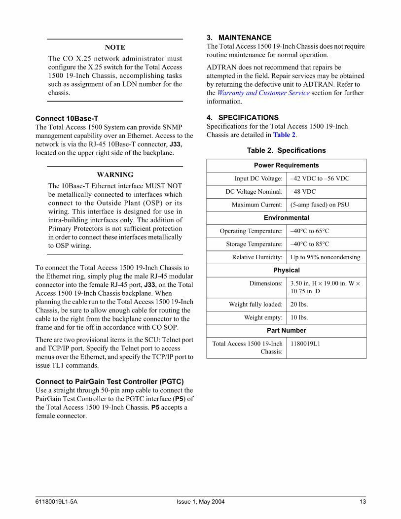
4. SPECIFICATIONSSpecifications for the Total Access 1500 19-Inch Chassis are detailed in Table 2.
Table 2. Specifications
Power Requirements
Input DC Voltage: –42 VDC to –56 VDC
DC Voltage Nominal: –48 VDC
Maximum Current: (5-amp fused) on PSU
Environmental
Operating Temperature: –40°C to 65°C
Storage Temperature: –40°C to 85°C
Relative Humidity: Up to 95% noncondensing
Physical
Dimensions: 3.50 in. H × 19.00 in. W × 10.75 in. D
Weight fully loaded: 20 lbs.
Weight empty: 10 lbs.
Part Number
Total Access 1500 19-InchChassis:
1180019L1
ay 2004 13
5. WARRANTY AND CUSTOMER SERVICEADTRAN will replace or repair this product within the warranty period if it does not meet its published specifi-cations or fails while in service. Warranty information can be found at www.adtran.com/warranty.
U.S. and Canada customers can also receive a copy of the warranty via ADTRAN’s toll-free faxback server at 877-457-5007.
• Request document 414 for the U.S. and Canada Carrier Networks Equipment Warranty.
• Request document 901 for the U.S. and Canada Enterprise Networks Equipment Warranty.
Refer to the following subsections for sales, support, CAPS requests, or further information.