FR Vous trouverez la traduction de cette notice sur le CD, avec d'autres informations
NL Vertaling van deze handleiding, als ook meer gegevens kan men terugvinden op de CD.
UK The translation of this manual and all other information can be found on the CD.
D Dieübersetzung dieser anleitung und alle anderen Informationen finden Sie auf der CD.
S Svensk Bruksanvisning och annan information finns på medföljande CD.
SF Tämän käyttöohjeen sekä muun informaation suomenkielinen käännös on oheisella CD:llä.
I La traduzione di questo manuale e tutte le informazioni concernenti l'unità possono essere trovate sul CD.
DK Oversættelsen af denne manual, samt alle øvrige informationer vedrørende enhederne, kan findes på CD'en.
SP La traducción de este manual de instrucciones y toda otra información sobre los dispositivos se encuentran en el CD
P A tradução deste Manual e toda a informação referente às unidades pode ser encontrada no CD
This device complies with Part 15 of the FCC Rules provided the enclosed instructions are followed to the letter. Use of the device is subject to the following conditions: (1) this device must not cause harmful interference and (2) the operation of this device should not be influenced by unwanted interference.
More information about FCC can be look at http://www.fcc.gov
3
Features:
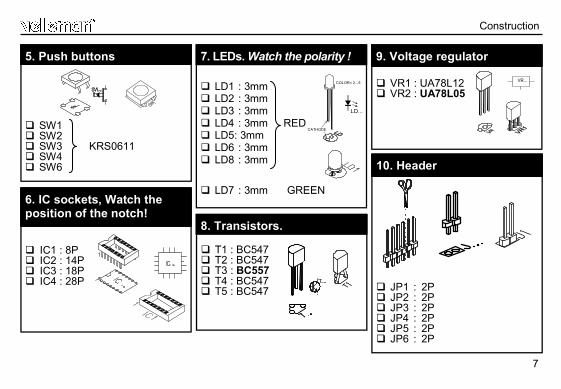
Suitable for programming Microchip® FLASH PIC(tm) microcontrollers Supports 4 different 300 mil. PICs: 8p, 14p, 18p and 28p Test buttons and LED indicators to carry out educational experiments, such as the enclosed programming examples Easy connection to a PC through the serial port Enclosed is a Flash Microcontroller (PIC16F627) that can be reprogrammed up to 1000 times for experimenting at will Software to compile and program your source code is included
Specifications:
Power supply: 12 or 15V DC, min. 300mA, non-regulated adapter (PS1205/PS1208/PS1508 5230Vac); PS1208USA (115Vac))
IBM Compatible PC, Pentium or better Windows™ 95/98/ME/NT/2000/XP CDROM free serial RS232 port
4
Assembly hints
1. Assembly (Skipping this can lead to troubles ! ) Ok, so we have your attention. These hints will help you to make this project successful. Read them carefully. 1.1 Make sure you have the right tools: • A good quality soldering iron (25-40W) with a small tip.
• Wipe it often on a wet sponge or cloth, to keep it clean; then apply solder to the tip, to give it a wet look. This is called ‘thinning’ and will protect the tip, and enables you to make good connections. When solder rolls off the tip, it needs cleaning.
• Thin raisin-core solder. Do not use any flux or grease.
• A diagonal cutter to trim excess wires. To avoid injury when cutting excess leads, hold the lead so they cannot fly towards the eyes.
• Needle nose pliers, for bending leads, or to hold components in place.
• Small blade and Phillips screwdrivers. A basic range is fine.
For some projects, a basic multi-meter is required, or might be handy
1.2 Assembly Hints :
⇒ Make sure the skill level matches your experience, to avoid disappointments. ⇒ Follow the instructions carefully. Read and understand the entire step before you perform each operation. ⇒ Perform the assembly in the correct order as stated in this manual ⇒ Position all parts on the PCB (Printed Circuit Board) as shown on the drawings. ⇒ Values on the circuit diagram are subject to changes. ⇒ Values in this assembly guide are correct* ⇒ Use the check-boxes to mark your progress. ⇒ Please read the included information on safety and customer service
* Typographical inaccuracies excluded. Always look for possible last minute manual updates, indicated as ‘NOTE’ on a separate leaflet.
0.000
5
Assembly hints
1.3 Soldering Hints :
1- Mount the component against the PCB surface and carefully solder the leads
2- Make sure the solder joints are cone-shaped and shiny
3- Trim excess leads as close as possible to the solder joint
REMOVE THEM FROM THE TAPE ONE AT A TIME !
AXIAL COMPONENTS ARE TAPED IN THE COR-RECT MOUNTING SEQUENCE !
6
R1 : 15K (1 - 5 - 3 - B) R2 : 220K (2 - 2 - 4 - B) R3 : 4K7 (4 - 7 - 2 - B) R4 : 1K (1 - 0 - 2 - B) R5 : 15K (1 - 5 - 3 - B) R6 : 220K (2 - 2 - 4 - B) R7 : 4K7 (4 - 7 - 2 - B) R8 : 1K (1 - 0 - 2 - B) R9 : 4K7 (4 - 7 - 2 - B) R10 : 3K3 (3 - 3 - 2 - B) R11 : 4K7 (4 - 7 - 2 - B) R12 : 330 (3 - 3 - 1 - B) R13 : 15K (1 - 5 - 3 - B) R14 : 1K (1 - 0 - 2 - B) R15 : 3K3 (3 - 3 - 2 - B) R16 : 1K (1 - 0 - 2 - B) R17 : 10K (1 - 0 - 3 - B) R18 : 10K (1 - 0 - 3 - B) R19 : 680 (6 - 8 - 1 - B) R20 : 680 (6 - 8 - 1 - B)
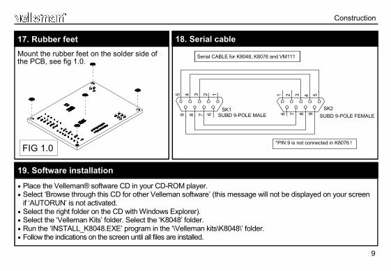
Mount the rubber feet on the solder side of the PCB, see fig 1.0.
17. Rubber feet
Construction
• Place the Velleman® software CD in your CD-ROM player. • Select ‘Browse through this CD for other Velleman software’ (this message will not be displayed on your screen
if ‘AUTORUN’ is not activated. • Select the right folder on the CD with Windows Explorer). • Select the ‘Velleman Kits’ folder. Select the ‘K8048’ folder. • Run the ‘INSTALL_K8048.EXE’ program in the ‘\Velleman kits\K8048\’ folder. • Follow the indications on the screen until all files are installed.


![274-824-6 EINECS - MASTER INVENTORY 274-850-8 274-824-6 ... · 274-824-6 EINECS - MASTER INVENTORY 274-850-8 1 EC_2748246_2759237 274-824-6 70729-60-1 etyl-[2-[etyl(3-metylfenyl)amino]fenyl]karbamát](https://static.documents.pub/doc/80x56/5e39c5c3e9db7d2db32094c4/274-824-6-einecs-master-inventory-274-850-8-274-824-6-274-824-6-einecs-master.jpg)


