Total Station A total station is an electronic/optical instrument used in modern surveying. The total station is an electronic theodolite (transit) integrated with an electronic distance meter (EDM) to read distances from the instrument to a particular point. In the 1950s optical theodolites were invented. This instrument was equipped with optical scales permitting directly digital readout or micrometer assissted readouts.Electronic theodolites first appeared in the 1960s. This instrument used photo electric converters capable of sensing horizontal and vertical angles and displaying those in degrees minutes and seconds. In 1980s total station appeared. This instrument combines electronic distance measurement (EDM) which was developed in 1950s with an electronic theodolite. This instrument is also equipped with cntral processor which enables the computation of horizontal and vertical positions. The central processor also monitors instrument status and perform wide variety of surveying applications. The total staion measure the horizontan and vertical angles and positions. All the data is then captued in the on board data sotorae or an external data storage Total Station DTM-302 Series
Transcript
Total Station
A total station is an electronic/optical instrument used in modern surveying. The total station is an electronic theodolite (transit) integrated with an electronic distance meter (EDM) to read distances from the instrument to a particular point.
In the 1950s optical theodolites were invented. This instrument was equipped with optical scales permitting directly digital readout or micrometer assissted readouts.Electronic theodolites first appeared in the 1960s. This instrument used photo electric converters capable of sensing horizontal and vertical angles and displaying those in degrees minutes and seconds.
In 1980s total station appeared. This instrument combines electronic distance measurement (EDM) which was developed in 1950s with an electronic theodolite. This instrument is also equipped with cntral processor which enables the computation of horizontal and vertical positions. The central processor also monitors instrument status and perform wide variety of surveying applications. The total staion measure the horizontan and vertical angles and positions. All the data is then captued in the on board data sotorae or an external data storage
Total Station DTM-302 SeriesThis series contains three models
1. DTM-3322. DTM-3523. DTM-362
The above one has single face LCD to display measurement while the other two have two displays to display the reading. Following are the parts of total station
Turning the Instrument On and Off 3.1
Turning on the instrument 31.1
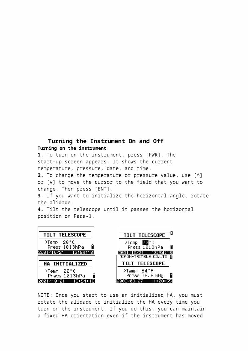
1. To turn on the instrument, press [PWR]. Thestart-up screen appears. It shows the current temperature, pressure, date, and time.2. To change the temperature or pressure value, use [^] or [v] to move the cursor to the field that you want to change. Then press [ENT].3. If you want to initialize the horizontal angle, rotate the alidade.4. Tilt the telescope until it passes the horizontal position on Face-1.
NOTE: Once you start to use an initialized HA, you must rotate the alidade to initialize the HA every time you turn on the instrument. If you do this, you can maintain a fixed HA orientation even if the instrument has moved while it is turned off. If you tilt the telescope before you rotate the alidade, the horizontal angle is not initialized, and the instrument uses the previous HA reading.
Turning off the instrument 30.1
To turn the instrument off, press [PWR] and [ENT]
BMS Basic measurement screen
DIFFERENT KEYS AND ITS FUNCTIONS
Switching between display screensWhen several display screens are available, the DSP indicator appears at the top left of the screen, and the screen indicator (for example, 1/4) appears at the top right.
Changing input mode while entering points or codesWhen the cursor is in a point (PT) or code (CD) field, press [MODE] to change the input mode between alphanumeric (A) and numeric (1).
Setting the horizontal angle to 0 41.1
To reset the horizontal angle to 0, press [1] or select 0-Set in the Angle menu. The display returns to the Basic Measurement Screen (BMS).
Entering the horizontal angle 41.2To display the HA Input screen, press [2] or select Input in the Angle menu. Use the numeric keys to enter the horizontal angle. Then press [ENT].
Recording a foresight point after repeat angle measurement 41.3
1. To activate repeat angle measurement, press [3] or select Rept. in the Angle menu.HR=0 appears.2. Sight the backsight and press [ENT].3. Sight the foresight and press [ENT].The horizontal angle is accumulated and thevalue is held again.
4. To end repeat angle measurement, press [ESC].
Horizontal angle hold 40.2
To hold the horizontal angle to the current value, press [5] or select Hold in the Angle menu. To set the horizontal angle to the displayed value, press [ENT] or the Set softkey. To cancel the process and return to the Basic Measurement Screen (BMS), press [ESC] or the Abrt softkey.
Jobs 3.3
To record data on the instrument, you must create or open a job. A job is a file that is use to store data.
Creating a new job 33.1
1. Press [MENU] to open the MENU screen.2. Press [1] to open the Job Manager.3. Press the Creat softkey to open the Create Job screen.4. Enter the job name.5. Press the Sett softkey to check the job settings. You cannot change a job’s settings once you have created the job.6. Press [ENT] in the last field of the Job Sett screen to create the new job.
Note : Before you use the instrument for the first time, check the job settings.Measuring Distances 3.1
Sighting a prism reflectorSight the telescope to see crosshairs at the center of theprism reflector. When a reflected lightwave is detected, the signal level isindicated.Measuring distances 31.2
To take a distance measurement, press [MSR1] or [MSR2] in the Basic Measurement Screen (BMS) orin any observation screen. While the instrument is taking a measurement, the prism constant appears in a small font. If the average count is set to 0, measurements are taken continuously until you press [MSR1], [MSR2], or [ESC]. Each time a measurement is taken, the distance is updated.If the average count is set to a value from 1 to 99, the averaged distance appears after the last shot. The field name SD changes to SDx to indicate the averaged data.Station Setup
There are seven procedures to setup a station in DTM 302 seriesTo open the Stn Setup menu, press [STN] in the BMS. To select a command from this menu, press the corresponding number key. Alternatively, press [<] or [>] to highlight the command and then press [ENT]. The last function used is highlighted.
(1)Setting up a station with known coordinates or azimuth 41.11. Press [1] or select Known in the Stn Setup menu.2. Enter a point name or number in the ST field.– If the input point number or name is anexisting point, its coordinates are displayed and the cursor moves to the HI (Height of instrument) field.– If the point is new, a coordinate input screen appears. Enter the coordinates for the point. Press [ENT] after each field. When you press [ENT] in the CD field, the new point is stored.– If the specified point has a code, the code appears in the CD field.3. Enter the instrument height in the HI field andthen press [ENT]. The Backsight screen appears.4. Select an input method for defining the backsight point.– To sight the backsight by entering coordinatesTo sight the backsight by entering the azimuth and angle,
(2) Setting up a station using multiple point resectionA resection sets up the station using angle/distance measurements to known points.You can use a maximum of 10 points in a resection. Measurements can be distance and angle, or angle only. Calculation starts automatically when enough measurements are taken.You can delete poor observations and recalculate if necessary. You can also select the BS point.If the angle between known point 1 and known point 2 (measured from the station point) is extremely acute or extremely oblique, the resulting solution will be less reliable geometrically. For geometric reliability, select known point locations (or station point locations) that are widely spaced.
(3) Setting up the station quickly without coordinates
The station point (ST) in this function defaults to a new point number. For the new point, MP (0, 0, 0) is stored as the coordinates. When the ST is manually changed to a known point name, the station is set up on the coordinates of the known point.To enter Quick Station setup, press [3] or select Quick in the Stn Setup menu.ST Station point (defaults to the last recorded PT + 1, or ST + 1, depending on the Split ST setting)HI Height of instrumentBS Backsight point (blank)AZ Backsight azimuth (defaults to zero)
(4) Determining station elevation 40.11. Press [4] or select Remote BM in the Stn Setup menu.2. Enter the BM point and press [ENT]. When the point is found, it appears briefly. The cursor then moves to the HT field.3. Enter the HT and press [ENT].4. Sight the BM point and press [MSR1] or [MSR2].
(5) BS Check (6) Base XYZ function:
(7) Two-point resection along a known line 40.11. To enter the Known Line function, press [7] orselect Known Line in the Stn Setup menu.2. Enter a known point as P1.If you enter a new point name, a coordinateinput screen appears.Sight P1 and press [MSR1] or [MSR2] to take ameasurement. Press [ENT].3. Choose how you want to define a known line:– To define the line by entering P2coordinates, press [1] or select By Coord.– To define the line by entering the azimuth,press [2] or select By Angle.
StakeoutFrom the practice by surveyors of using stakes to measure out an area before the main building project is commenced here it means to stake the points on the grounds that are derived after modeling in a software or so.To display the Stakeout menu, press [S-O]. There are four procedure for stakeout function
(1) Specifying the stakeout point by angle and distance1. To display the input screen for the distance and angle to the target, press [1] or select HA-HD in the Stakeout menu.2. Enter the values and press [ENT]. HD Horizontal distance from station point to stakeout point dVD Vertical distance from station point to stakeout point HA Horizontal angle to stakeout point
If you press [ENT] without entering HA, the current HA is used3. Rotate the instrument until the dHA is close to 0°00'00".4. Sight the target and press [MSR1] or [MSR2]. When the measurement is completed, the differences between the target position and the stakeout point are displayed.dHA Difference in horizontal angle to the target pointR/L Right/Left (Lateral error)IN/OUT In/Out (Longitudinal error)CUT/FIL Cut/FillOnce a measurement is taken, the Cut/Fill value and Z coordinate are updated as the VA is changed.
(2) Specifying the stakeout point by coordinates1. To start a stakeout by coordinates, press [2] or select XYZ in the Stakeout menu.2. Enter the point name that you want to stake and press [ENT].You can also specify the point by code or radius from the instrument.If several points are found, they are displayed in a list. Use [^] or [v] to move up and down the list. Use [<] or [>] to move up or down one page.3. Highlight a point in the list and press [ENT].
The delta angle and the distance to the target are shown. 4. Rotate the instrument until the dHA is close to 0°00'00". Press [MSR1] or [MSR2].dHA Difference in horizontal angle to the target pointHD Distance to the target point5. Ask the Rodman(person having target) to adjust the target position. When the target is on the intended position, the displayed errors become 0.000 m (or 0.000 ft).dHA Difference in horizontal angle to the target pointR/L Right/Left (Lateral error)IN/OUT In/Out (Longitudinal error)CUT/FIL Cut/Fill
Adjustments in Total Station
Checking and Adjusting the Plate Level 6.1The axis of the plate level vial must be at right angles to the vertical axis of theinstrument.To check and adjust the plate level:1. Set up the instrument on the tripod.2. Follow the leveling procedures 3. Rotate the alidade 180°.4. Check whether the bubble is in the center of the vial.5. If the bubble is not in the center of the vial, adjust the plate level:a. Using the adjusting pin supplied, rotatethe plate level’s adjustment screw untilthe bubble has moved half of thedistance back to the center.b. Using leveling screw A, move thebubble into the center of the vial.c. Repeat from Step 4.
Checking and Adjusting the Circular Level 6.1
Once you have checked and adjusted the plate
level, check the circular level. If the bubble is not in the center of the level,use the adjusting pin to rotate the threeadjustment screws until the bubble is centered.
Checking and Adjusting the Optical Plummet 6.2
The optical axis of the plummet must be aligned with the vertical axis of theinstrument.To check and adjust the optical plummet:1. Place the instrument on the tripod. You do not have to level the instrument.2. Place a thick sheet of paper marked with an X onthe ground below the instrument.While you are looking through the opticalplummet, adjust the leveling screws until theimage of the X is in the center of the reticlemark .3. Rotate the alidade 180°.If the marked image is in the same position inthe center of the reticle mark, no adjustment isrequired.4. If the image is not in the same position,adjust the optical plummet:a. Use the supplied hexagonal wrench toturn the adjustment screws until theimage of the X is in Position P. PositionP is the center point of the lineconnecting the X and the center of thereticle mark .5.Centre and Check again
Checking and Adjusting the Telescope1. mark X on an obstacle in the front of telescope at angle of about 450 with the horizontal up and about 450 down2. rotate the instrument 1800 and site the mark below the horizontal3. Clamp the horizontal plate and site the mark above by tilting the telescope4. if the mark is in the cross hairs of the telescope then there is no adjustment required5. if the mark is away from the cross hairs rotate the adjustment screw for telescope till the half distance P is reached.6. Level and check again 6.2