32
2101562–001 rev. AB Totalflow ® ABB Multivariable (XMV) with Totalflow XSeries Equipment User’s Manual

2101562–001 rev. AB
Totalflow®
ABB Multivariable (XMV) with Totalflow XSeries Equipment User’s Manual

Intellectual Property & Copyright Notice
©2009 by ABB Inc., Totalflow (“Owner”), Bartlesville, Oklahoma 74006, U.S.A. All rights reserved. Any and all derivatives of, including translations thereof, shall remain the sole property of the Owner, regardless of any circumstances. The original US English version of this manual shall be deemed the only valid version. Translated versions, in any other language, shall be maintained as accurately as possible. Should any discrepancies exist, the US English version will be considered final. Notice: This publication is for information only. The contents are subject to change without notice and should not be construed as a commitment, representation, warranty, or guarantee of any method, product, or device by Owner. Inquiries regarding this manual should be addressed to ABB Inc., Totalflow Products, Technical Communications, 7051 Industrial Blvd., Bartlesville, Oklahoma 74006, U.S.A.
i
TABLE OF CONTENTS INTRODUCTION ...................................................................................................... IV
Organization & Style................................................................................................... iv Chapter Descriptions.................................................................................................. iv Getting Help ............................................................................................................... iv
Before Calling ...............................................................................................................iv Key Symbols .............................................................................................................. iv Safety Practices and Precautions ............................................................................... v
Safety Guidelines ......................................................................................................... v Safety First ................................................................................................................... v Equipment Markings.....................................................................................................vi Grounding the Product .................................................................................................vi Operating Voltage.........................................................................................................vi Danger From Loss of Ground.......................................................................................vi Safe Equipment ............................................................................................................vi
1.0 MECHANICAL INSTALLATION................................................................. 1–1 1.1 Unpacking and Inspection ........................................................................... 1–1
1.1.1 Unpacking.................................................................................................... 1–1 1.1.2 Inspection .................................................................................................... 1–1 1.1.3 Damaged Components................................................................................ 1–1
1.2 Pipe Mount Installation ................................................................................ 1–1 1.2.1 Flange Type Manifold Assembly ................................................................. 1–1 1.2.2 Non - Flange Type Manifold Assembly ....................................................... 1–3
1.3 Direct Mount Installation .............................................................................. 1–3 1.3.1 Step-by-Step Instructions ............................................................................ 1–4
2.0 XMV SETUP ............................................................................................... 2–1 2.1 Overview...................................................................................................... 2–1 2.2 XMV Setup .................................................................................................. 2–1 2.3 XMV Setup With Display and Keys ............................................................. 2–1 2.4 XMV Setup Without Display and Keys ........................................................ 2–2 2.5 Adding a Display and Keys to an XMV........................................................ 2–4
2.5.1 Adjusting the XMV Static Pressure Response Time ................................... 2–4 3.0 XSERIES SETUP TO SUPPORT THE ABB XMV...................................... 3–1
3.1 XSeries Configuration Files ......................................................................... 3–1 3.2 XMV Support Applications........................................................................... 3–1 3.3 XMV Interface.............................................................................................. 3–2 3.4 XMV Communications Port Setup ............................................................... 3–3 3.5 Assigning XMVs to Measurement Tubes .................................................... 3–9 3.6 Displays for XMV ....................................................................................... 3–10
4.0 XSERIES TO ABB XMV WIRING AND INTERCONNECT......................... 4–1 4.1 Summary ..................................................................................................... 4–3
ii
TABLE OF FIGURES Figure 1–1 Pipe Mount Assembly – Flange Manifold .........................................................................1–2 Figure 1–2 Pipe Mount Assembly – Flange Manifold .........................................................................1–2 Figure 1–3 Pipe Mount Assembly – Non Flange Manifold..................................................................1–3 Figure 1–4 Side Assembly Direct Mount.............................................................................................1–4 Figure 2–1 Push Button Key Menu .....................................................................................................2–1 Figure 2–2 TFModbus.........................................................................................................................2–3 Figure 2–3 Device Address Screen ....................................................................................................2–3 Figure 2–4 TFModbus Device Communication...................................................................................2–3 Figure 3–1 PCCU Application Screen.................................................................................................3–2 Figure 3–2 PCCU XMV Setup ............................................................................................................3–2 Figure 3–3 PCCU XMV1 Setup ..........................................................................................................3–3 Figure 3–5 XMV MRB Registers, Address 1.......................................................................................3–4 Figure 3–6 XMV MRB Registers, Address 2.......................................................................................3–4 Figure 3–7 XMV MRB Registers, Address 3.......................................................................................3–5 Figure 3–8 XMV MRB Registers, Address 4.......................................................................................3–5 Figure 3–9 XMV MRB Registers, Address 5.......................................................................................3–5 Figure 3–10 XMV MRB Registers, Address 6.....................................................................................3–6 Figure 3–12 Save and Restore Utility .................................................................................................3–7 Figure 3–14 Modbus Host Request Block Editor ................................................................................3–8 Figure 3–15 MRB Entry Screen ..........................................................................................................3–9 Figure 3–16 XMV Values Screen (APP/ARRAY/REG).......................................................................3–9 Figure 3–17 PCCU Menu Bar (Calibrate) .........................................................................................3–10 Figure 3–18 PCCU32 Calibrate Measurement Tubes ......................................................................3–10 Figure 4–1 Wiring and Interconnect XMV to XSeries, Pg. 1...............................................................4–1 Figure 4–2 Wiring and Interconnect XMV to XSeries, Pg. 2...............................................................4–2 Figure 4–3 Back View of the XMV ......................................................................................................4–3

iii
LIST OF TABLES Table 2—1 XMV Menu Tree............................................................................................................... 2–2 Table 2—2 XMV Display & Keys Parts List........................................................................................ 2–4 Table 3—1 Standard Configuration Files ........................................................................................... 3–1
iv
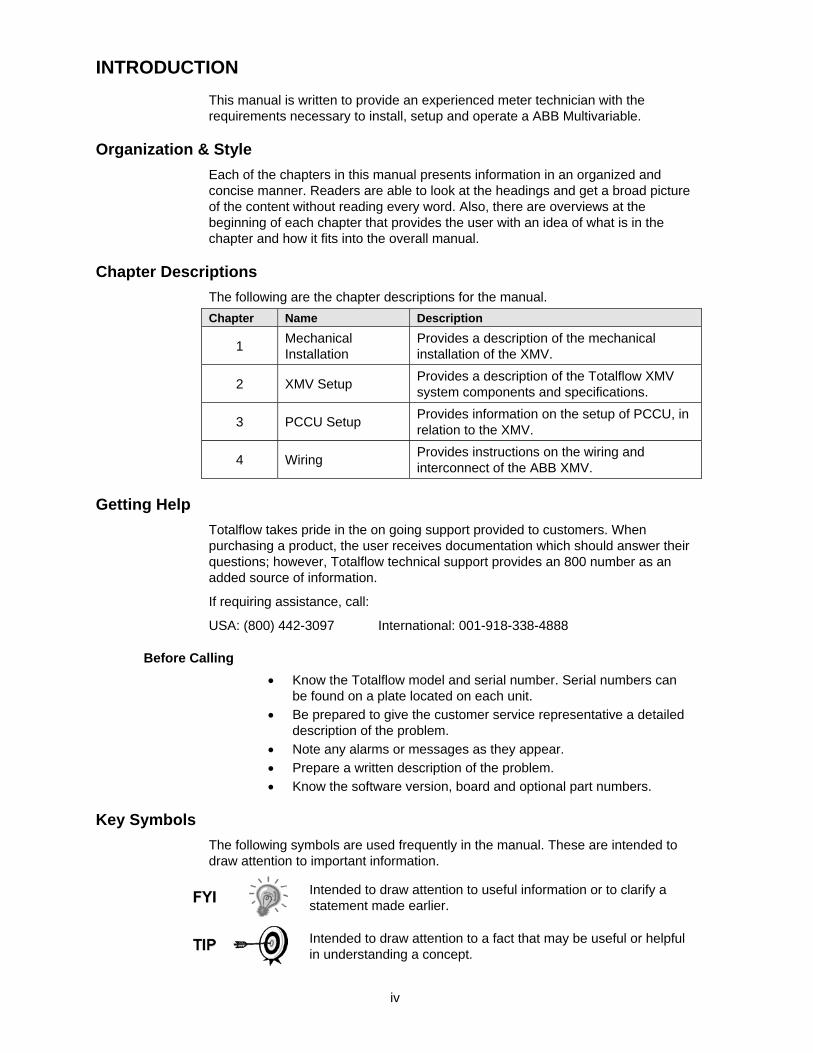
INTRODUCTION This manual is written to provide an experienced meter technician with the requirements necessary to install, setup and operate a ABB Multivariable.
Organization & Style Each of the chapters in this manual presents information in an organized and concise manner. Readers are able to look at the headings and get a broad picture of the content without reading every word. Also, there are overviews at the beginning of each chapter that provides the user with an idea of what is in the chapter and how it fits into the overall manual.
Chapter Descriptions The following are the chapter descriptions for the manual. Chapter Name Description
1 Mechanical Installation
Provides a description of the mechanical installation of the XMV.
2 XMV Setup Provides a description of the Totalflow XMV system components and specifications.
3 PCCU Setup Provides information on the setup of PCCU, in relation to the XMV.
4 Wiring Provides instructions on the wiring and interconnect of the ABB XMV.
Getting Help Totalflow takes pride in the on going support provided to customers. When purchasing a product, the user receives documentation which should answer their questions; however, Totalflow technical support provides an 800 number as an added source of information.
If requiring assistance, call:
USA: (800) 442-3097 International: 001-918-338-4888
Before Calling • Know the Totalflow model and serial number. Serial numbers can
be found on a plate located on each unit. • Be prepared to give the customer service representative a detailed
description of the problem. • Note any alarms or messages as they appear. • Prepare a written description of the problem. • Know the software version, board and optional part numbers.
Key Symbols The following symbols are used frequently in the manual. These are intended to draw attention to important information.
Intended to draw attention to useful information or to clarify a statement made earlier.
Intended to draw attention to a fact that may be useful or helpful in understanding a concept.

v
Intended to draw attention to a statement that might keep the user from making a mistake, keep the user from destroying equipment or parts or keep the user from creating a situation that could cause personal injury, if caution is not used. Please refer to the “Safety Practices and Precaution” section for additional information.
Intended to draw attention to a statement regarding the likelihood of personal injury or fatality that could result from improper access or techniques used while working in hazardous locations. Please refer to the “Safety Practices and Precaution” section for additional information.
Safety Practices and Precautions This manual contains information and warnings which have to be followed by the user to ensure safe operation and to retain the product in a safe condition. Installation, maintenance and repairs should only be performed by a trained and qualified technician. Please refer to certification drawings, shipped with this unit, for specific guidelines. Extra copies of the certification drawings, referenced on the unit name tag, can be obtained, free of charge, by contracting Totalflow technical support at the number listed in the “Getting Help” section.
Safety Guidelines • DO NOT open the equipment to perform any adjustments,
measurements, maintenance, parts replacement or repairs until all external power supplies have been disconnected.
• Only a properly trained technician should work on any equipment with power still applied.
• When opening covers or removing parts, exercise extreme care. Live parts or connections can be exposed.
• Installation and maintenance must be performed by person(s) qualified for the type and area of installation, according to national and local codes.
• Capacitors in the equipment can still be charged, even after the unit has been disconnected from all power supplies.
Safety First
Various statements in this manual, identified as conditions or practices that could result in equipment damage, personal injury or loss of life, will be highlighted using the following icons.
Exercise caution while performing this task. Carelessness could result in damage to the equipment, other property and personal injury.

vi
STOP. Do not proceed without first verifying that a hazardous condition does not exist. This task may not be undertaken until proper protection has been adopted, or the hazardous condition has been removed. Personal injury or fatality could result. Examples of these warnings include: • Removal of enclosure cover(s) in a hazardous location must
follow guidelines stipulated in the certification drawings shipped with this unit.
• If unit is installed or to be installed in a hazardous location, technician must follow the guidelines stipulated in the certification drawings shipped with this unit.
• Access to the unit via PCCU cable in a hazardous location must follow guidelines stipulated in the certification drawings shipped with this unit.
• Connecting or disconnecting equipment in a hazardous location for installation or maintenance of electric components must follow guidelines stipulated in the certification drawings shipped with this unit.
WARNING indicates a personal injury hazard immediately accessible as one reads the markings. CAUTION indicates a personal injury hazard not immediately accessible as one reads the markings or a hazard to property, including the equipment itself.
Equipment Markings
Protective ground (earth) terminal.
Grounding the Product
If a grounding conductor is required, it should be connected to the grounding terminal before any other connections are made.
Operating Voltage
Before switching on the power, check that the operating voltage listed on the equipment agrees with the power being connected to the equipment.
Danger From Loss of Ground
A grounding conductor may or may not be required, depending on the hazardous classification. If required, any interruption of the grounding conductor inside or outside the equipment or loose connection of the grounding conductor can result in a dangerous unit. Intentional interruption of the grounding conductor is not permitted.
Safe Equipment
If it is determined that the equipment cannot be operated safety, it should be taken out of operation and secured against unintentional usage.

2101562-001 (AB) Page 1–1
1.0 MECHANICAL INSTALLATION This chapter provides the user with the information for the installation and setup of the Totalflow XMV. By the time this chapter is concluded, the XMV should be unpacked, installed and ready for operation.
Read through this chapter before beginning the installation.
1.1 Unpacking and Inspection
1.1.1 Unpacking
The XMV is shipped in a specially designed shipping carton which contains the unit, parts list and wiring and interconnect diagrams.
Carefully remove the items from each carton.
1.1.2 Inspection • Inspect the shipping carton for damage. If the shipping carton is damaged,
keep it until the contents have been inspected for damage. • Inspect the unit’s exterior for dents, chipped paint, etc. • Inspect the LCD window for breakage. • Open the housing by first removing the bolt and releasing the latch/latches. • Visually inspect the electronics and XMV unit for damage.
1.1.3 Damaged Components
If any components have been damaged or if there are noticeable defects, notify the Totalflow representative. Keep all shipping materials for the carrier’s inspection. Totalflow will arrange for immediate repair or replacement.
1.2 Pipe Mount Installation If the user is installing directly to the mounting pipe, the following procedure should be used. Before beginning, review the procedure and the materials required for installation.
There are different methods of installing the XMV mounting bracket. The following willl cover the more popular methods.
1.2.1 Flange Type Manifold Assembly
1.2.1.1 Materials Supplied
• Two U-bolts plus fastening hardware • XMV mounting bracket
1.2.1.2 Step-by-Step Instructions
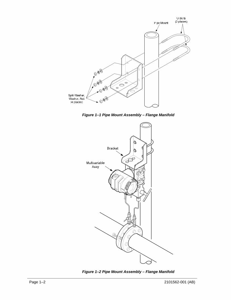
1) Ascertain where the XMV is to be placed on the mounting pipe.
2) Once decided, secure the bracket to the mounting pipe with two U-bolts, flat washers, split washers and bolts (see ).
3) Once the bracket is attached to the pipe, attach the XMV to the underside of the bracket, using four bolts (see Figure 1–2).
Page 1–2 2101562-001 (AB)
Figure 1–1 Pipe Mount Assembly – Flange Manifold
Figure 1–2 Pipe Mount Assembly – Flange Manifold
2101562-001 (AB) Page 1–3
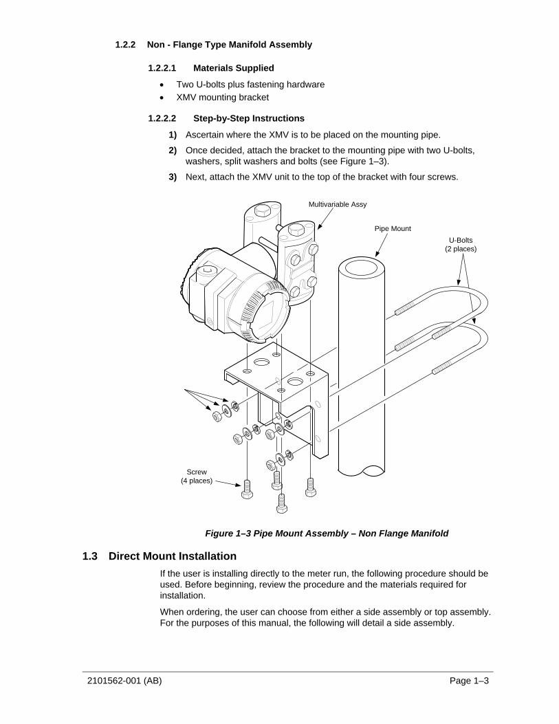
1.2.2 Non - Flange Type Manifold Assembly
1.2.2.1 Materials Supplied
• Two U-bolts plus fastening hardware • XMV mounting bracket
1.2.2.2 Step-by-Step Instructions
1) Ascertain where the XMV is to be placed on the mounting pipe.
2) Once decided, attach the bracket to the mounting pipe with two U-bolts, washers, split washers and bolts (see Figure 1–3).
3) Next, attach the XMV unit to the top of the bracket with four screws.
Pipe MountU-Bolts
(2 places)
Screw(4 places)
Multivariable Assy
Figure 1–3 Pipe Mount Assembly – Non Flange Manifold
1.3 Direct Mount Installation If the user is installing directly to the meter run, the following procedure should be used. Before beginning, review the procedure and the materials required for installation.
When ordering, the user can choose from either a side assembly or top assembly. For the purposes of this manual, the following will detail a side assembly.

Page 1–4 2101562-001 (AB)
1.3.1 Step-by-Step Instructions
1) Attach the XMV to the manifold and align bolt holes (see Figure 1–4).
2) Using the supplied bolts, bolt the manifold securely to the XMV.
3) Next, using the supplied bolts, secure the manifold assembly to the meter run.
Figure 1–4 Side Assembly Direct Mount

2101562-001 (AB) Page 2–1
2.0 XMV SETUP
2.1 Overview This document describes the setup of an ABB Multivariable transmitter (XMV).
2.2 XMV Setup The XMV measures static pressure, differential pressure and process temperature in a gas, vapor or liquid media. The XMV is a 2-wire, RS-485 Modbus device with two additional wires required for power. It has a permissible terminal voltage range of 10.5 – 30 VDC. The current draw is 10 mA per XMV. The unit must be set up to operate with the XFC or XRC flow computers.
2.3 XMV Setup With Display and Keys An optional Push Button Key Unit is located at the top of the XMV (see Figure 2–1). It is used to setup the configuration parameters in the XMV. To make the keys accessible, release the screw and flip the protective cap aside. Pushing the key down with an instrument screwdriver activates the key. See the menu tree below in Table 2—1.
With the mode key “M”, the user can start the menu-controlled programming. To call the next menu item, press the “+” key. To call the previous menu item, press the “-“ key. Sub-menu items / selection list are activated via the mode “M” key. A numerical value can be changed using the “+” key to increment the value by 1 and the “-“ key to move the curser to the left. The mode “M” key is used to accept the changes. When setup is finished, go to the menu “Exit” screen, and press the mode “M” key.
Figure 2–1 Push Button Key Menu

Page 2–2 2101562-001 (AB)
Table 2—1 XMV Menu Tree
Enter Program Menu with Mode Key ‘M’ Description Typical Setting
Exit N/A
View Any (Not Used)
Shift Zero None (Not Used)
Damping 0.125 Seconds
Device Mode Operate
Baud Rate 9600
Bus Address 1 (Set 1–8 as required)
Resp-Delay 20 Ms
Display User Text*
Exit N/A
Upon exit from the XMV setup mode, the display will show SP, DP or temperature from the XSeries, if communications are operational OR the message, “User-Text”, will appear. This indicates the XMV is waiting on the XSeries to write the display data.
2.4 XMV Setup Without Display and Keys An XMV without a display and keys may be setup using a PC, running PCCU software with a RS-485 communication link to the XMV. Use a RS-232 to RS-485 converter assembly (2100241-002) and adapter cable (2100248-001) to make this connection. On the adapter cable, the “Bus –“ (black alligator clip) connects to XMV “Com –“ terminal. “Bus +” (red alligator clip) connects to XMV “Com +” terminal. The XMV must be powered up from an external power source, during this setup sequence.
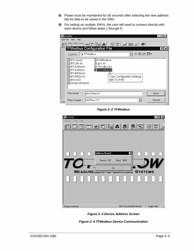
1) Open the “TFModbus” utility in PCCU (see Figure 2–2).
2) Open “XmvSetup.ini”.
3) The INI program will cycle through the Modbus addresses and baud rates until it communicates with the XMV (see Figure 2–3). The address search will stop when the XMV responds. The current Modbus address and baud rate of the XMV are displayed in the address search box.
4) Please note the device address of the XMV, then click the OK button.
5) If the address is correct and the response delay is 20 ms, no further action is needed for setup on this device. Skip to Step 8.
6) If the address is correct, but the response delay is not 20 ms, select a different address tab and then reselect the original address tab so the response delay parameter will be updated to 20 ms in the XMVsetup.ini. Skip to step 8; otherwise, continue to step 7.
7) If a different address is required, select the Tab with the required address. The Xmvsetup.ini will re-address the XMV to the address specified and set the response delay to 20 ms. The process data will be read and displayed from the XMV, using the new address and setup parameters.
2101562-001 (AB) Page 2–3
8) Power must be maintained for 60 seconds after selecting the new address tab for data to be saved in the XMV.
9) For setting up multiple XMVs, the user will need to connect directly with each device and follow steps 1 through 8.
Figure 2–2 TFModbus
Figure 2–3 Device Address Screen
Figure 2–4 TFModbus Device Communication
Page 2–4 2101562-001 (AB)
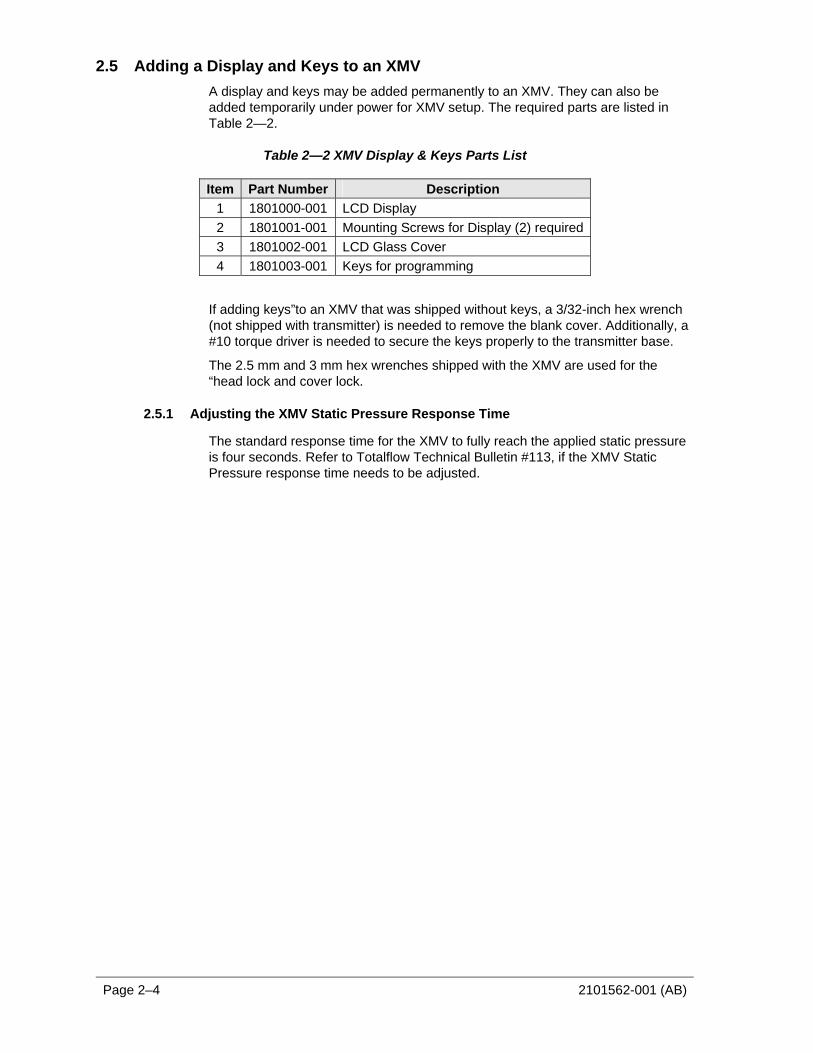
2.5 Adding a Display and Keys to an XMV A display and keys may be added permanently to an XMV. They can also be added temporarily under power for XMV setup. The required parts are listed in Table 2—2.
Table 2—2 XMV Display & Keys Parts List
Item Part Number Description 1 1801000-001 LCD Display 2 1801001-001 Mounting Screws for Display (2) required 3 1801002-001 LCD Glass Cover 4 1801003-001 Keys for programming
If adding keys”to an XMV that was shipped without keys, a 3/32-inch hex wrench (not shipped with transmitter) is needed to remove the blank cover. Additionally, a #10 torque driver is needed to secure the keys properly to the transmitter base.
The 2.5 mm and 3 mm hex wrenches shipped with the XMV are used for the “head lock and cover lock.
2.5.1 Adjusting the XMV Static Pressure Response Time
The standard response time for the XMV to fully reach the applied static pressure is four seconds. Refer to Totalflow Technical Bulletin #113, if the XMV Static Pressure response time needs to be adjusted.

2101562-001 (AB) Page 3–1
3.0 XSERIES SETUP TO SUPPORT THE ABB XMV
3.1 XSeries Configuration Files Totalflow has standard configuration files (see Table 3–1) that have all the setup parameters and support files for use with the XMV. Totalflow recommends using these released files, when possible.
A few of the standard configuration files for use with the XSeries and XMVs are shown below. Contact Totalflow for other available configurations.
Table 3—1 Standard Configuration Files
Part Number Description 2100961-xxx XFC with AGA3 support for 1-3 ABB XMVs
2100922-xxx XRC with AGA3 support for 1 ABB XMV
2100962-xxx XRC with AGA3 support for 1-4 ABB XMVs
2101469-xxx XRC with AGA3 support for 1-6 ABB XMVs with Station totals for pod applications
1) All standard XMV configuration files are built to support the XMV with
display. If the display is not used, the user should delete the MVxxTXT.mrb files in the Modbus folder under the XMV communications port.
2) If one of the multi-tube XMV configurations are used, the actual number of XMVs must be entered within PCCU under the Communication Setup tab. The user should un-instantiate any unused measurement tubes by setting the application to ‘spare’ within the Applications tab. The user should also delete the associated display group in “Save and Restore” in the tfData/Display folder to customize the configuration files for a specific configuration.
3.2 XMV Support Applications To support an XMV with an XSeries flow computer, the following applications are required (see Figure 3–1):
1) XMV Interface Application—typically instantiated at app# 8.
2) Communications Application—typically COM 2 instantiated at app# 3.
3) Measurement Tube Application—typically instantiated at app# 11-18 as required.
4) Display Application—typically instantiated at app# 23 with a display group for each measurement tube.
Page 3–2 2101562-001 (AB)
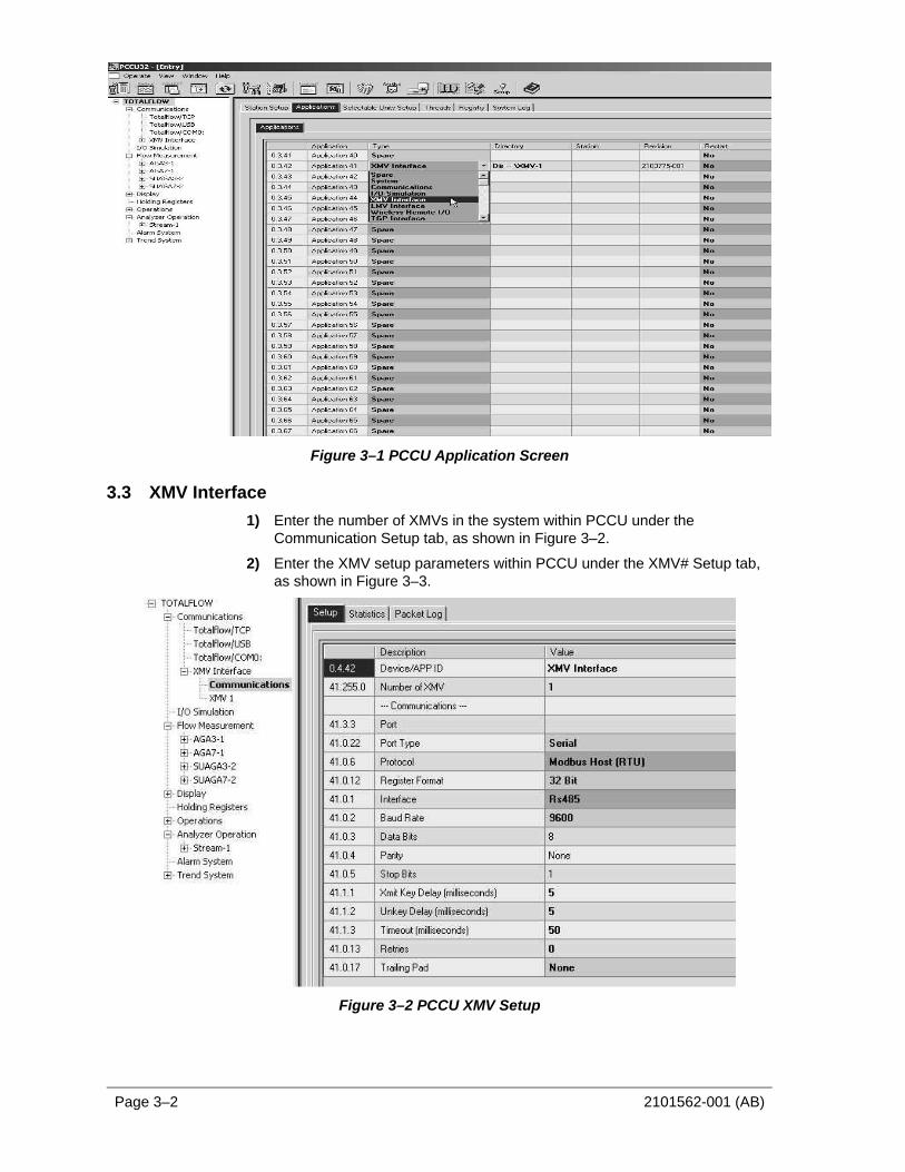
Figure 3–1 PCCU Application Screen
3.3 XMV Interface 1) Enter the number of XMVs in the system within PCCU under the
Communication Setup tab, as shown in Figure 3–2.
2) Enter the XMV setup parameters within PCCU under the XMV# Setup tab, as shown in Figure 3–3.
Figure 3–2 PCCU XMV Setup

2101562-001 (AB) Page 3–3
Figure 3–3 PCCU XMV1 Setup
3.4 XMV Communications Port Setup 1) Setup the Communication Port parameters (see Figure 3–4) in PCCU under
Communications in the tree-view.
Figure 3–4 Setup Parameters
2) Setup the Communication Port MRB(s) (Modbus Request Block).
In step 1, a “Modbus” folder was created for the communications port. There are two supported types of MRBs. The user needs to determine which method is desired and create the required Modbus Request Block(s).

Page 3–4 2101562-001 (AB)
Legacy Method • The Legacy method uses two Modbus blocks per XMV and is supported by all
versions of the XSeries Flash software. There are two Modbus Request Blocks (MRB) that need to be created and stored in the Modbus folder for each XMV installed (See Figure 3–5 through Figure 3–10, as needed).
Mv1.MRB (block one) is required for reading registers from the XMV and storing the raw values into the XMV application.
Mv1Txt.MRB (block two) writes the SP, DP & temperature data to the XMV display.
Figure 3–5 XMV MRB Registers, Address 1
Figure 3–6 XMV MRB Registers, Address 2

2101562-001 (AB) Page 3–5
Figure 3–7 XMV MRB Registers, Address 3
Figure 3–8 XMV MRB Registers, Address 4
Figure 3–9 XMV MRB Registers, Address 5

Page 3–6 2101562-001 (AB)
Figure 3–10 XMV MRB Registers, Address 6
• Interface Controlled Method
The Interface Controlled method uses one Modbus block and is supported by all XSeries Flash software released after 4/21/2004 (XFC flash 2101050-011 and XRC flash 2101052-009 and later). Regardless of the number of XMVs used, this method requires one Modbus block (see Figure 3–11).
Figure 3–11 XMV Interface Control Block
3) Once the method is determined, the required block(s) must be created.
Instructions shown are for using PCCU 4.53 or later. If using PCCU4.52 or earlier, the blocks must be created and saved to the users PC hard drive and then downloaded, using the “Save and Restore” utility, to the Modbus folder under the XMV Com Port.
4) Go to “File Utilities” and then “Save and Restore” in the Operate menu (see ).
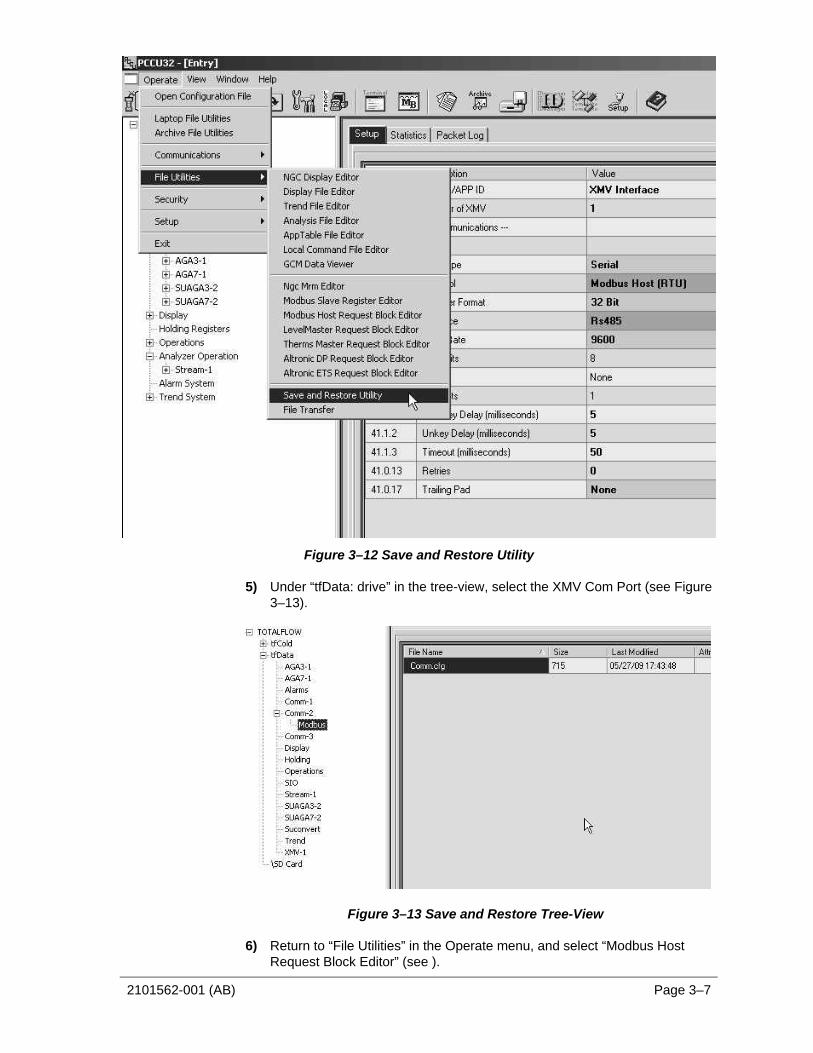
2101562-001 (AB) Page 3–7
Figure 3–12 Save and Restore Utility
5) Under “tfData: drive” in the tree-view, select the XMV Com Port (see Figure 3–13).
Figure 3–13 Save and Restore Tree-View
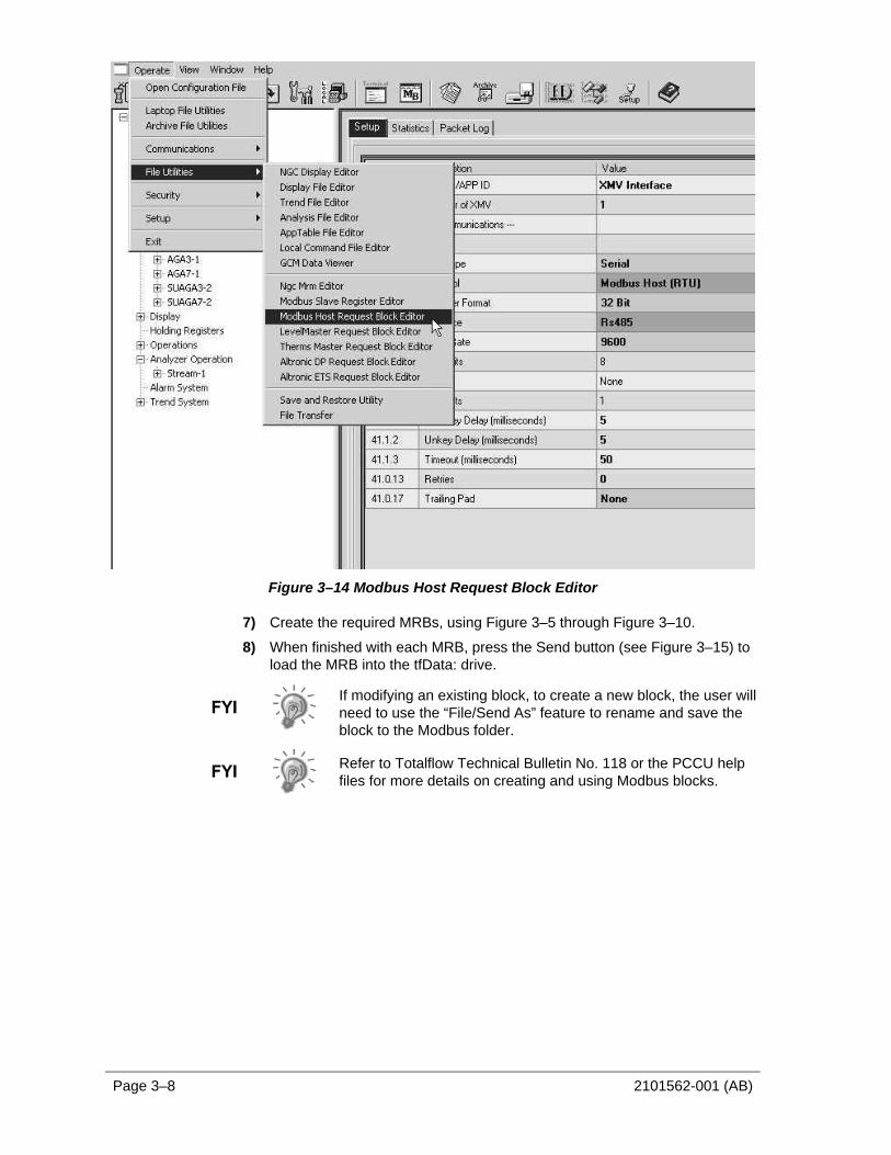
6) Return to “File Utilities” in the Operate menu, and select “Modbus Host Request Block Editor” (see ).
Page 3–8 2101562-001 (AB)
Figure 3–14 Modbus Host Request Block Editor
7) Create the required MRBs, using Figure 3–5 through Figure 3–10.
8) When finished with each MRB, press the Send button (see Figure 3–15) to load the MRB into the tfData: drive.
If modifying an existing block, to create a new block, the user will need to use the “File/Send As” feature to rename and save the block to the Modbus folder.
Refer to Totalflow Technical Bulletin No. 118 or the PCCU help files for more details on creating and using Modbus blocks.

2101562-001 (AB) Page 3–9
Figure 3–15 MRB Entry Screen
3.5 Assigning XMVs to Measurement Tubes The data inputs from the XMVs can be assigned to any measurement tube.
1) To assign the input, the user must note the App/Array/Register for the scaled values for each XMV (see Figure 3–16).
2) Next, click the Calibration icon(see Figure 3–17).
3) Select the measurement tube to be configured from the tree-view (see Figure 3–18).
4) Select the Setup tab.
5) Enter the appropriate App/Array/Register for static pressure, differential pressure and temperature on the Values tab.
Figure 3–16 XMV Values Screen (APP/ARRAY/REG)

Page 3–10 2101562-001 (AB)
Figure 3–17 PCCU Menu Bar (Calibrate)
Figure 3–18 PCCU32 Calibrate Measurement Tubes
3.6 Displays for XMV There are no actual displays in the XSeries for the XMV. Instead, the XMV is typically assigned to a measurement tube, and the measurement tube has an associated display group. If a measurement tube has been added, a display group for that tube needs to be added with the following procedure:
1) Move to the Save and Restore utility.
2) Go to the Display folder on tfData, and double-click on an existing display group for a measurement tube.
3) Modify the group name, display names and display registers for the new measurement tube.
4) Use the “File / Send As…” option to download the modified file with a new file name to the Display folder.
5) Go to “Entry “ mode and check displays.

2101562-001 (AB) Page 4–1
4.0 XSERIES TO ABB XMV WIRING AND INTERCONNECT
WIR
ING
& IN
TER
CO
NN
ECT
XMV
TO X
SER
IES/
TFIO
WI
NO
NE
BW
I21
0157
6A
D1
2
-- -----
TOTA
LFLO
W
AD
D20
731
AB
D15
944
AC
D16
854
NO
TES:
1FO
R RT
D IN
STA
LLA
TION
-RE
MO
VE
JUM
PERS
FRO
M X
MV
TER
MIN
ALS
11-
12, 1
3-14
AN
D T
HE
178
R
ESIS
TOR
FRO
M T
ERM
INA
LS 1
2-14
.
2TH
E RS
485
BUSS
MUS
T BE
WIR
ED IN
A D
AIS
Y-C
HAIN
CO
NFI
GUR
ATIO
N.
STA
R C
ON
FIG
URA
TION
S A
RE N
OT
ALL
OW
ED.
3BU
SS T
ERM
INA
TION
S -
THE
RS48
5 BU
SS IS
TER
MIN
ATE
D O
N T
HE
HOST
EN
D W
ITH J
UMPE
RS.
THE
LAST
XM
V O
N T
HE
BUSS
SHO
ULD
BE
TERM
INA
TED
WITH
A12
4
(120
-
250
IS
AC
CEP
TABL
E) R
ESIS
TOR
AC
ROSS
THE
CO
MM
+ A
ND
CO
MM
- TER
MIN
ALS
.TH
E 17
8
RES
ISTO
R D
ISC
ARD
ED IN
NO
TE 1
IS A
CC
EPTA
BLE
FOR
BUSS
TER
MIN
ATIO
N.
MO
ST R
S485
BUS
S IN
STA
LLA
TION
S D
O N
OT
REQ
UIRE
BUSS
TER
MIN
ATIO
N F
OR
CO
RREC
T O
PERA
TION
.
Figure 4–1 Wiring and Interconnect XMV to XSeries, Pg. 1
Page 4–2 2101562-001 (AB)
CO
MM
2RS
485
CO
MM
MO
DUL
E
2100
204-
XXX
2100
355-
XXX
XFC
G4
PCBA
XRC
G4
PCBA
2102
838-
XXX
2103
022-
XXX
BRN
RED
1 2XM
T-XM
T+
2011
648-
001
RS48
5 C
ABL
E,6
CO
ND
UCTO
R
RTD
WHT
BLK
WHT
BLK
14 13
12 11
SUPP
LY/C
OM
M-
+
-
+
BLK
WHT
BRN
RED
RTD
14 13
WH
T
WH
T
BLK
BLK
12 11
-
+
-
+SU
PPLY
/CO
MM
CIM
-XXJ
3
TERM
+
TERM
-
1 2
BLK
WHT
BRN
RED1 1
3 2BUSS
TER
MIN
ATIO
N
TERM
+1
TERM
-
3
BUSS
TER
MIN
ATIO
NJ7
- C
OM
M1
2 13
TERM
-
TERM
+
J10
- CO
MM
2J1
2 - C
OM
M2
3
BUSS
TER
MIN
ATIO
N3
2
3
P6A
GN
D
VBA
TT
BUS-
BUS+
11 10 15 17 BUSS
TER
MIN
ATIO
NJ7
- C
OM
M1
2 13
TERM
-
TERM
+
J10
- CO
MM
23
P6B
NO
NE
BW
I21
0157
6AD
2
6413
/641
4 XF
C
FCU1
95 P
CBA
6490
XRC
RTU1
95 P
CBA
TFIO
CIM
-XX
2100
421-
003
CIM
-XX
CO
MM
2C
OM
M 1
RS48
5 C
OM
MRS
485
CO
MM
MO
DUL
EM
OD
ULE
ABB
XM
VM
ULTIV
ARI
ABL
ES16
4102
0-XX
X16
4102
1-XX
X
GN
D
VBA
TT
BUS-
BUS+
GN
D
VBA
TT
BUS-
BUS+
1 2 13 12
2 1 6 8
GN
D
VBA
TT
RCV
-RC
V+
CIM
-XXJ
1
CIM
-XXJ
2
3 4 2 1
BLK
WHT
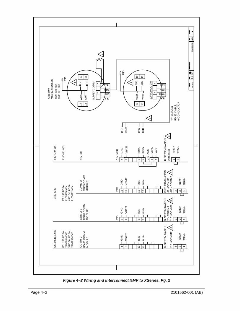
Figure 4–2 Wiring and Interconnect XMV to XSeries, Pg. 2
2101562-001 (AB) Page 4–3
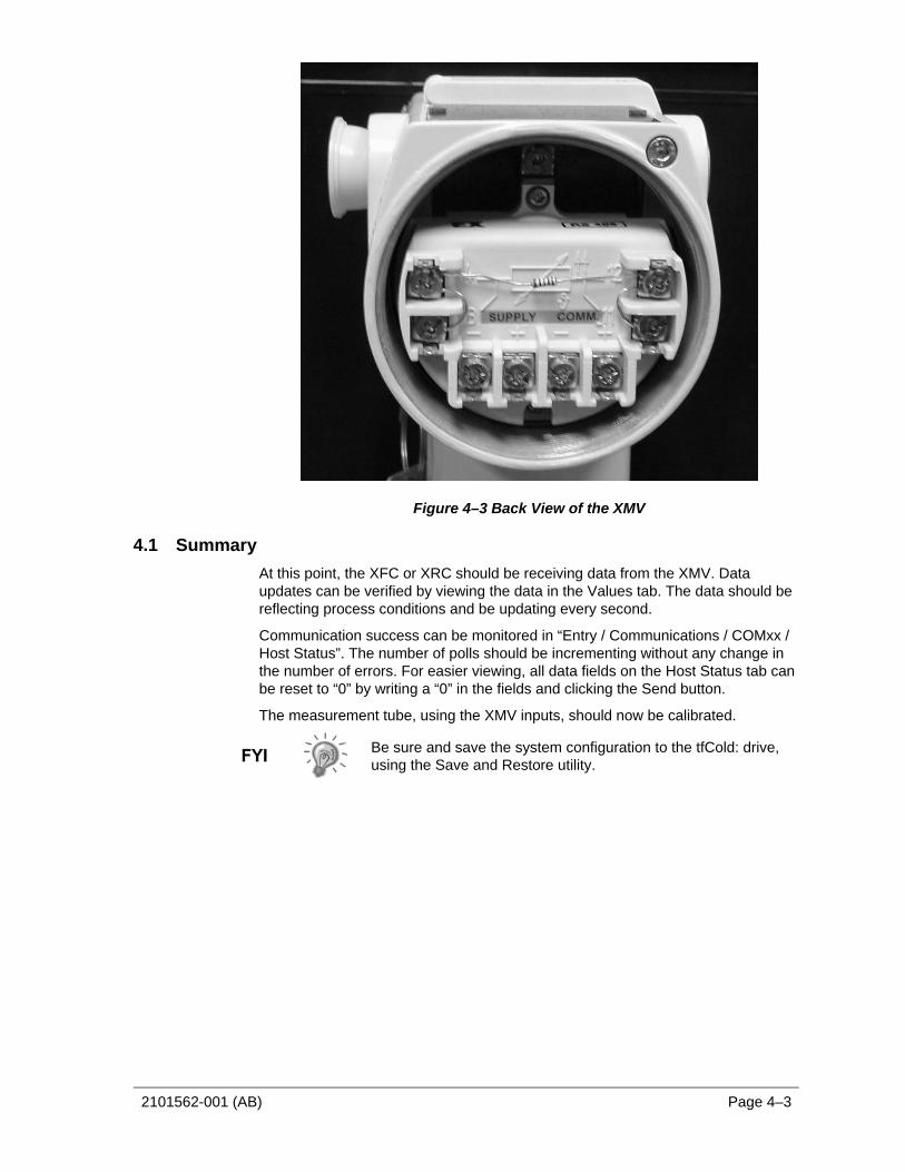
Figure 4–3 Back View of the XMV
4.1 Summary At this point, the XFC or XRC should be receiving data from the XMV. Data updates can be verified by viewing the data in the Values tab. The data should be reflecting process conditions and be updating every second.
Communication success can be monitored in “Entry / Communications / COMxx / Host Status”. The number of polls should be incrementing without any change in the number of errors. For easier viewing, all data fields on the Host Status tab can be reset to “0” by writing a “0” in the fields and clicking the Send button.
The measurement tube, using the XMV inputs, should now be calibrated.
Be sure and save the system configuration to the tfCold: drive, using the Save and Restore utility.

Page 4–4 2101562-001 (AB)
BBBlllaaannnkkk PPPaaagggeee


ABB Inc. Totalflow Products 7051 Industrial Blvd. Bartlesville, Oklahoma 74006 Tel: USA (800) 442-3097
International 001-918-338-4880


