57
Trench Products Catalog 2018 PRECAST TRENCH SOLUTIONS . TOUGH ENOUGH TO TRUST

Trench Products Catalog2018
PRECAST TRENCH SOLUTIONS.
TOUGH ENOUGHTO TRUST

Trenwaphone: 859-781-0831 fax: 859-781-1085
e-mail: [email protected]
1419 Alexandria PikeFt. Thomas, KY 41075
www.trenwa.com
• Introduct ion - 4 • One Piece Mult ipurpose trench - 7
• Light Traff ic H10 trench - 17• Road Crossing H20 trench - 19
• Component Pedestr ian trench - 33•Accessories - 40
•Specs & Instal lat ion - 51
When vieWed on-line this catalog is interactive. click on blue text to jump to the section in catalog or to details on Website.
Table Of COnTenTs

4
Revised 6/20/18
Introduction - BenefitsBACKGROUNDTrenwa manufactures a variety of precast concrete trench systems for the distribution of electrical control cables, power cables and mechanical piping. Sales and engineering support are provided from offices in Fort Thomas, Kentucky, a suburb of Cincinnati. With production plants across the United States, Trenwa can service the entire North American conti-nent. In fact, Trenwa has shipped material to all 50 states and nine Canadian provinces.
Trenwa’s original Component trench design was developed by Cincinnati Gas & Electric Company engineers in the mid 1950’s to provide a means of locating and protecting control cables in sub-stations, especially those stations where future growth was anticipated. The design was so innovative that it was granted a U.S. patent and its unique "U"-shaped bracket continues to be the company’s logo today. Trenwa later introduced additional trench designs including the One Piece trench, Road Crossing trench, and XL trench.
BENEFITS OF USING TRENCH
ECONOMY - Trenwa trenches are often more economical than poured-in-place trench with its expensive forming costs or duct banks with their costly cable pulling. ACCESSIBILITY - Unlike duct bank or direct buried systems, Trenwa trenches provide accessibility for future maintenance or expansion. DURABILITY - Trenwa trench systems are proven trench systems which are more durable than lighter-weight alternatives.
FLEXIBILITY - With a wide range of sizes, Trenwa trenches can meet the capacity needs of almost any customer. In addition, a limitless number of layout configurations can be created using tees, crosses, horizontal and vertical angles, side by side trenches, and cross-unders. LEAK CONTAINMENT - Trenwa solid bottom trenches with sealants and damp-proof coatings provide leak containment for piping.
OPTIONS & ACCESSORIES - • Design loads ranging from Pedestrian loading to HS40 (highway load-ing) or greater • Embedded Unistrut or Weld Plates • Cable Support Blocks • Ground Cable Clips • Cable Risers • Dividers • Steel Ventilator Lids • Guard Posts
5
Revised 6/20/18
Introduction - Trench Types
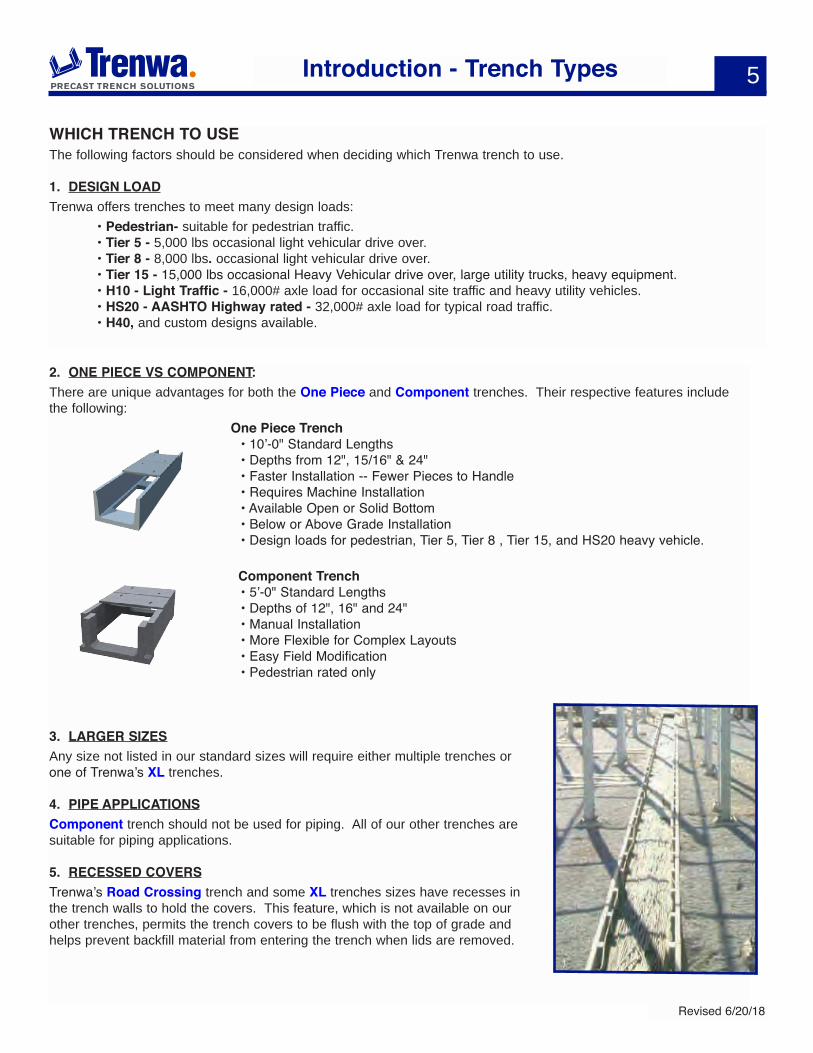
WHICH TRENCH TO USEThe following factors should be considered when deciding which Trenwa trench to use.
1. DESIGN LOADTrenwa offers trenches to meet many design loads: • Pedestrian- suitable for pedestrian traffic. • Tier 5 - 5,000 lbs occasional light vehicular drive over. • Tier 8 - 8,000 lbs. occasional light vehicular drive over. • Tier 15 - 15,000 lbs occasional Heavy Vehicular drive over, large utility trucks, heavy equipment. • H10 - Light Traffic - 16,000# axle load for occasional site traffic and heavy utility vehicles. • HS20 - AASHTO Highway rated - 32,000# axle load for typical road traffic. • H40, and custom designs available.
2. ONE PIECE VS COMPONENT:There are unique advantages for both the One Piece and Component trenches. Their respective features include the following: One Piece Trench • 10’-0" Standard Lengths • Depths from 12", 15/16" & 24" • Faster Installation -- Fewer Pieces to Handle • Requires Machine Installation • Available Open or Solid Bottom • Below or Above Grade Installation • Design loads for pedestrian, Tier 5, Tier 8 , Tier 15, and HS20 heavy vehicle.
Component Trench • 5’-0" Standard Lengths • Depths of 12", 16" and 24" • Manual Installation • More Flexible for Complex Layouts • Easy Field Modification • Pedestrian rated only
3. LARGER SIZESAny size not listed in our standard sizes will require either multiple trenches or one of Trenwa’s XL trenches.
4. PIPE APPLICATIONSComponent trench should not be used for piping. All of our other trenches are suitable for piping applications.
5. RECESSED COVERSTrenwa’s Road Crossing trench and some XL trenches sizes have recesses in the trench walls to hold the covers. This feature, which is not available on our other trenches, permits the trench covers to be flush with the top of grade and helps prevent backfill material from entering the trench when lids are removed.
6
Revised 6/20/18
It's Easy to Work With Trenwa!
Although you can use this catalog to design and develop a bill of materials and place an order consisting of quantities and part numbers, in most cases it is better to let us design the project. Working with us from the quoting stage through the design and delivery of the project is a simple process and our Project Managers will guide and support you all the way.
Design Assistance-we will be glad to discuss your requirements and help you with design ideas and recommend the optimum trench for your project.
Budgetary pricing- if you have a simple project in mind and need budgetary pricing for engineering estimates give us a call or email us and we can get you a budget price rather quickly. All we need to know is the type of trench, linear footage involved, sizes and load rating of trenches, and the number of turns and tees.
Quotation- to get a firm price on a project out for bid we would prefer to get a bid package consisting of written specs and site plan drawings. These can be sent to us via email, with attachments, at [email protected].
Or you can mail them to: Trenwa, Inc. 1419 Alexandria Pike Fort Thomas, KY 41075
If you prefer you can fax the information to us at 859-781-1085.
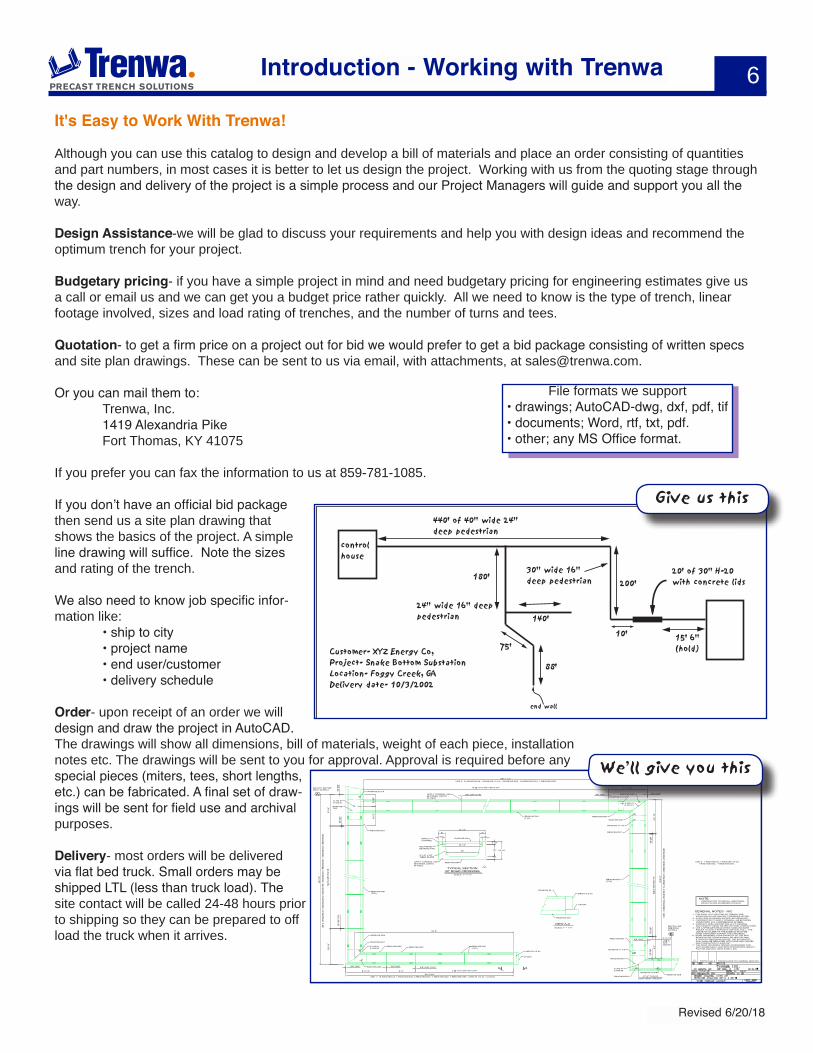
If you don’t have an official bid package then send us a site plan drawing that shows the basics of the project. A simple line drawing will suffice. Note the sizes and rating of the trench.
We also need to know job specific infor-mation like: • ship to city • project name • end user/customer • delivery schedule
Order- upon receipt of an order we will design and draw the project in AutoCAD. The drawings will show all dimensions, bill of materials, weight of each piece, installation notes etc. The drawings will be sent to you for approval. Approval is required before any special pieces (miters, tees, short lengths, etc.) can be fabricated. A final set of draw-ings will be sent for field use and archival purposes.
Delivery- most orders will be delivered via flat bed truck. Small orders may be shipped LTL (less than truck load). The site contact will be called 24-48 hours prior to shipping so they can be prepared to off load the truck when it arrives.
control house
440' of 40" wide 24" deep pedestrian
180'200'
end wall
10'140'
20' of 30" H-20 with concrete lids
24" wide 16" deep pedestrian
Customer- XYZ Energy Co,Project- Snake Bottom SubstationLocation- Foggy Creek, GADelivery date- 10/3/2002
30" wide 16" deep pedestrian
88'
75'15' 6"(hold)
3 3/8"
6"
43 1/2"
RA3016S-24
6"
36 1/2"
30" 16" 23 1/2"
3 1/2"
4"
3 3/8"
TYPICAL SECTION30" ROAD CROSSING
SCALE: 1" = 1'-0"
RB3016S-D01
IMPACTCHANNEL
8" x 8" x 3/8" WELD PLATE
NEOPRENEBEARING PAD
APPLY CONSEAL 440BETWEEN JOINTSIN FIELD
VIEW A-ASCALE: 1" = 1'-0"
RB3016S-D01
DRC16 1/2 43
L61243
RA3016S-24
1. FOR EACH 10'-0" SECTION OF TRENCH USE; 5-RA3016S-24 LIDS UNLESS OTHERWISE NOTED.2. PLAN VIEW AS DRAWN SHOWS LIDS REMOVED.3. CONTRACTOR TO APPLY CONSEAL 440 BETWEEN JOINTS WITH 50% COMPRESSION IN FIELD.4. COMPACT AREA AROUND WALLS TO ORIGINAL SOIL DENSITY USING WATER OR HAND COMPACTORS.5. USE A SPREADER BEAM WHEN HANDLING BASE PIECES TO GIVE A STRAIGHT VERTICAL PULL. THE LARGE SHOULDER OF THE EYEBOLT MUST BE HAND TIGHTENED AGAINST THE CONCRETE.
GENERAL NOTES - R/C
6. ROAD CROSSING- LOAD CAPACITY OF THE SOIL BENEATH THE TRENCH SHALL BE 4000 PSF MIN. IF WATER CONDITIONS OCCUR, THE SATURATED SOIL SHALL BE REPLACED WITH SAND AND GRAVEL AND COMPACTED TO 4000 PSF.7. THE ROAD CROSSING TRENCH IS DESIGNED FOR H-20 32,000# AXLE LOAD WITH APPROPRIATE IMPACT FACTOR AND WILL HAVE STEEL LIDS.
NOTE:CONTRACTOR TO INSTALL ADDITIONAL WELD PLATES AS NEEDED IN FIELD.
7 @ 10
'-0 3/
8"=70
'-2 5/
8"
18 @ 10'-0 3/8"=180'-6 3/4"
S 193.81E 633.41
90'-0
1/2"
188'-7 1/4"
A
MATCH LINE SEE DWG. 02-089-2
USE 2
: 40-R
A301
6S-24
, 1-R
A301
6S-20
1/4,
1-RA3
016S
-TEE,
1-RA3
016S
-D01
, 7-R
B301
6S-D
01, 1
-RB3
016S
-D03
, 1-R
B301
6S-D
04.
USE 3: 91-RA3016S-24, 1-RA3016S-13 1/2, 1-RA3016S-D02, 18-RB3016S-D01, 1-RB3016S-D06.
A A
3/8" G
AP3/8
" GAP
3/8" GAP (TYP)APPLY CONSEAL 440 BETWEEN JOINTSIN FIELD
3'-5 3
/4"
9'-3 1
/4"
5'-9 1
/2"
S 193.81E 548.6510
'-6 1/
4"
8'-2 1/4" 6'-0" 2 @ 10'-0 3/8"=20'-0 3/4"
34'-3 3/4"
RB3016S-D01(TYP)
7'-11 3/4"
DRC16 1/2 43
L61243
RB3016S-D04
RB3016S-D05
RA3016S-20 1/4
RA3016S-TEE
3/8" G
AP (T
YP)
RB3016S-D03
RB3016S-D02 RB3016S-D01(TYP)
RA3016S-D01
RA3016S-D02
USE 1: 15-RA3016S-24, 1-RA3016S-D02, 2-RB3016S-D01, 1-RB3016S-D02, 1-RB3016S-D05, 1-DRC16 1/2 43, 1-L61243.
RA3016S-D02
RB3016S-D01(TYP)
3/8" GAP (TYP)
32'-6"
3/8" GAP 3/8" GAP
RB3016S-D01(TYP)
RA3016S-D01
RA3016S-13 1/2
RB3016S-D06
RB3016S-D07
9'-11
1/2"
3/8" GAP 3/8" GAP
RA3016S-17 1/4
RB3016S-D07
RA3016S-D01
RA3016S-17 1/4
3/8" G
AP6 @
10'-0
3/8"=
60'-2
1/4"
6'-4"
3/8" G
AP
76'-6
1/2"
3/8" GAP4'-10 1/2"
3/8" G
AP
S 382.41E 633.41
S 382.41E 556.86
MATCH LINE SEE DWG. 02-089-2
27'-6" TO OFLC
EAST-WEST TRENCH
USE 4
: 34-R
A301
6S-24
, 2-R
A301
6S-17
1/4,
2-RA3
016S
-D01
, 6-R
B301
6S-D
01, 2
-RB3
016S
-D07
.
USE 5:SEEABOVE.
RA3016S-D02
RA3016S-19 3/4RB3016S-D08
B
USE 5: 1-RA3016S-24, 1-RA3016S-19 3/4, 1-RA3016S-D02, 1-RB3016S-D08.
1 bec d. TRENCH WAS 7K LOADING, NOW R/C.5/22/02
1
Introduction - Working with Trenwa
File formats we support • drawings; AutoCAD-dwg, dxf, pdf, tif • documents; Word, rtf, txt, pdf. • other; any MS Office format.
We’ll give you this
Give us this
Trenwaphone: 859-781-0831 fax: 859-781-1085
e-mail: [email protected]
1419 Alexandria PikeFt. Thomas, KY 41075
www.trenwa.com
Overview - 8
• Multi-Duty Base & Lids - 9• HS10 Light Traffic Base & Lids - 16
• HS20 Road Crossing Base & Lids -18 • Slopes & Crossunders - 26
• Ventilator Lids -28
One PieCe TrenCh
8
Revised 6/20/18
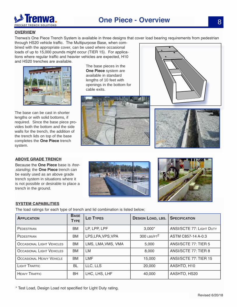
OVERVIEWTrenwa's One Piece Trench System is available in three designs that cover load bearing requirements from pedestrian through HS20 vehicle traffic. The Multipurpose Base, when com-bined with the appropriate cover, can be used where occasional loads of up to 15,000 pounds might occur (TIER 15). For applica-tions where regular traffic and heavier vehicles are expected, H10 and HS20 trenches are available.
The base pieces in the One Piece system are available in standard lengths of 10 feet with openings in the bottom for cable exits.
The base can be cast in shorter lengths or with solid bottoms, if required. Since the base piece pro-vides both the bottom and the side walls for the trench, the addition of the trench lids on top of the base completes the One Piece trench system.
One Piece - Overview
ABOVE GRADE TRENCHBecause the One Piece base is free-standing, the One Piece trench can be easily used as an above grade trench system in situations where it is not possible or desirable to place a trench in the ground.
SYSTEM CAPABILITIESThe load ratings for each type of trench and lid combination is listed below;
aPPliCaTiOnbase TyPe
lid TyPes design lOad, lbs. sPeCifiCaTiOn
Pedestrian BM LP, LPP, LPF 3,000* ansi/sCte 77: Light duty
Pedestrian BM LPs,LPa,VPs,VPa 300 LBs/Ft2 astM C857-14 a-0.3
OCCasiOnaL Light VehiCLes BM LMs, LMa,VMs, VMa 5,000 ansi/sCte 77: tier 5OCCasiOnaL Light VehiCLes BM LM 8,000 ansi/sCte 77: tier 8
OCCasiOnaL heaVy VehiCLe BM LMF 15,000 ansi/sCte 77: tier 15
Light traFFiC BL LLC, LLs 20,000 aashtO, h10
heaVy traFFiC Bh LhC, Lhs, LhF 40,000 aashtO, hs20
* Test Load, Design Load not specified for Light Duty rating.
9
Revised 6/20/18
One Piece - Multipurpose Base
PLAN VIEW
10'-0"
12"42"
OPEN OPEN
END VIEW3"
W+6"
2"
W
D=15”
END VIEW3"
W+6"
2"
W-2" D=24"
END VIEW3"
W+6"
2 1/8"
W
D=12”
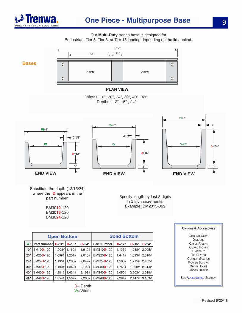
Specify length by last 3 digits in 1 inch increments.
Example: BM2015-069
Substitute the depth (12/15/24) where the D appears in the
part number.
BM3012-120 BM3015-120BM3024-120
Widths: 10", 20", 24", 30", 40" , 48" Depths : 12", 15" , 24"
Bases
D= DepthW=Width
1,160# 1,288#
1,251# 1,593#
1,288# 1,715#
1,342# 1,898#1,745#
1,434# 2,203#
Part Number Part NumberD=15" D=24" D=15" D=24"
Open Bottom Solid Bottom
BM10D-120
BM20D-120
BM24D-120
BM30D-120
BM40D-120
BMS10D-120
BMS20D-120
BMS24D-120
BMS30D-120
BMS40D-120
1,919#
2,010#
2,047#
2,102#
2,193#
10"
20"
24"
30"
40"
48"
2,005#
2,310#
2,432#
2,614#
2,919#
1,507#
1,008#
1,099#
1,135#
1,190#
1,281#
D=12"
1,354# 2,447#
1,136#
1,441#
1,563#
2,050#
D=12"
2,294#BM48D-120 BMS48D-1202,266# 3,163#
W*
OPTiOns & aCCessOries
grOund CLiPs diViders
CaBLe risersguard POsts
unistruttie PLates
COrner guardsPOwer BLOCksdrain hOLes
CrOss drains
see aCCessOries seCtiOn
Our Multi-Duty trench base is designed for Pedestrian, Tier 5, Tier 8, or Tier 15 loading depending on the lid applied.

10
Revised 6/20/18
One Piece - Pedestrian Lids
Trenwa offers both galvanized steel and aluminum lids in a pedestrian rating. The steel lids are made of 1/4" hot dip galvanized checker plate. The aluminum lids are made of 1/4" aluminum checker plate and are very light weight. They have stiffener and locator bars on the bottom surface. All lids have 1/2" holes for lifting with our LTSM tool.
ALONG LENGTH OF TRENCH
L
1/4"
W+6"
1/4" checker plate
Steel LidsPart NumberW LLPS10-4010" 40" 70#LPS20-3020" 30" 75#LPS24-3024" 30" 105#LPS30-3030" 30" 130#LPS40-2040" 20" 130#LPS48-2048" 20" 155#
Weight Part NumberW LLPA10-6010" 60" 30#LPA20-6020" 60" 45#LPA24-6024" 60" 55#LPA30-6030" 60" 68#LPA40-60LPA48-60
40" 60"60"
90#110#
Weight
48"
Aluminum Lids
Steel & Aluminum Pedestrian Lids
LIFTING SLOTS
L
2 1/2"
2"
1 1/4"
W+6"W(span)
Concrete Pedestrian Lids
Concrete Pedestrian Lids
Our Fiber Reinforced Concrete, FRC, pedestrian lids, are made of steel, struc-tural fiber, and 8,000 psi concrete. They are rated for pedestrian traffic and proof tested to 3,000 lbs uniform loading. Part number LP.
Our Polymer Modified Concrete, PMC, lids are constructed like our FRC lids but with a Polymer Modifier added to the concrete. This increases the durability and reduces water and chloride penetra-tion increasing the longevity of these lids. Part number LPP.
More details on our website.
PrOOF LOadtested tO 3,000 LBs.
Part NumberFRC PMC
Part NumberW L WeightLP10-3010" 30" 70#LP20-3020" 30" 65#LP24-3024" 30" 80#LP30-3030" 30" 95#LP40-2040" 20" 90#LP48-20
LPP10-30LPP20-30LPP24-30LPP30-30LPP40-20LPP48-2048" 20" 130#
11
Revised 6/20/18
One Piece - Pedestrian Composite Lids
Fibrelite™ Pedestrian Lids
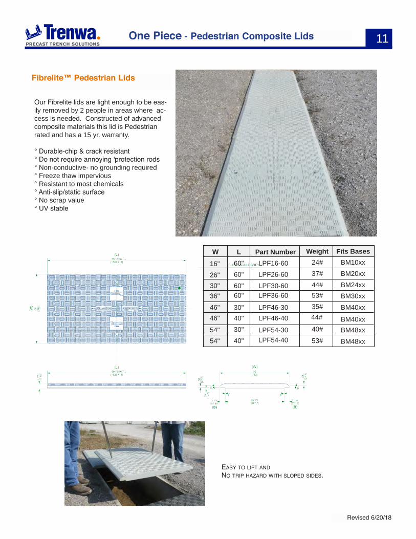
Our Fibrelite lids are light enough to be eas-ily removed by 2 people in areas where ac-cess is needed. Constructed of advanced composite materials this lid is Pedestrian rated and has a 15 yr. warranty.
° Durable-chip & crack resistant° Do not require annoying 'protection rods° Non-conductive- no grounding required° Freeze thaw impervious° Resistant to most chemicals° Anti-slip/static surface° No scrap value° UV stable
easy tO LiFt and nO triP hazard with sLOPed sides.
Part NumberW LLPF16-60 BM10xx
BM20xxBM24xxBM30xxBM40xxBM40xxBM48xxBM48xx
16" 60" 24#
LPF26-6026" 60" 37#
LPF30-6030" 60" 44#LPF36-6036" 60" 53#
LPF46-4046" 40" 44#LPF46-3046" 30" 35#
LPF54-30LPF54-40
54"54"
30"40"
40#53#
Weight Fits Bases
12
Revised 6/20/18
One Piece - Lids
Concrete Tier 8 Lids
3"
W+6
2 1/2"Ferrule NC-13 pre-galvanizedlifting insert
60"
260#420#480#580#
730#
LM10-60LM20-60LM24-60LM30-60
LM40-60
10"20"24"30"
40"
830#LM48-6048"
Part NumberW Weight
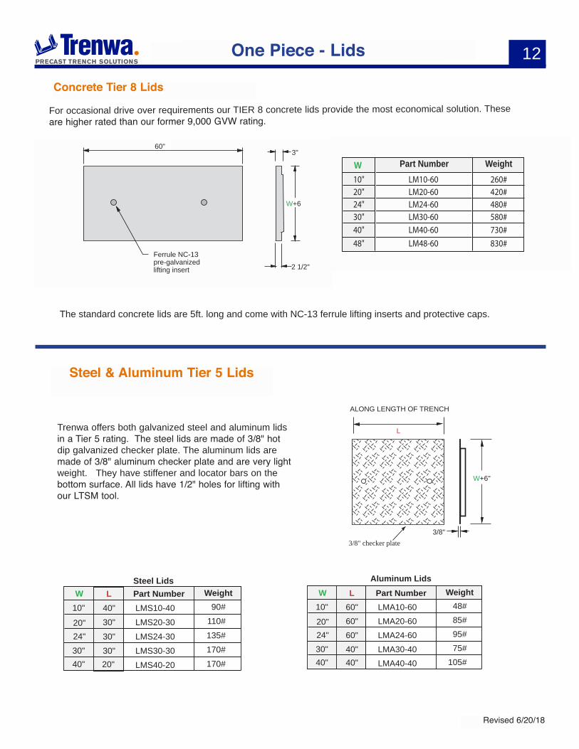
The standard concrete lids are 5ft. long and come with NC-13 ferrule lifting inserts and protective caps.
Trenwa offers both galvanized steel and aluminum lids in a Tier 5 rating. The steel lids are made of 3/8" hot dip galvanized checker plate. The aluminum lids are made of 3/8" aluminum checker plate and are very light weight. They have stiffener and locator bars on the bottom surface. All lids have 1/2" holes for lifting with our LTSM tool.
For occasional drive over requirements our TIER 8 concrete lids provide the most economical solution. These are higher rated than our former 9,000 GVW rating.
ALONG LENGTH OF TRENCH
L
3/8"
W+6"
3/8" checker plate
Part NumberW LLMS10-4010" 40" 90#
LMS20-3020" 30" 110#
LMS24-3024" 30" 135#
LMS30-3030" 30" 170#
LMS40-2040" 20" 170#
WeightSteel Lids
Steel & Aluminum Tier 5 Lids
Part NumberW LLMA10-6010" 60" 48#
LMA20-6020" 60" 85#
LMA24-6024" 60" 95#
LMA30-4030" 40" 75#
LMA40-4040" 40" 105#
WeightAluminum Lids
13
Revised 6/20/18
One Piece - TIER 15 Composite Lids
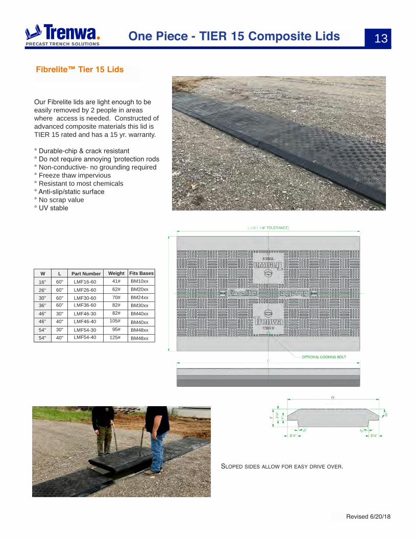
Fibrelite™ Tier 15 Lids
Our Fibrelite lids are light enough to be easily removed by 2 people in areas where access is needed. Constructed of advanced composite materials this lid is TIER 15 rated and has a 15 yr. warranty.
° Durable-chip & crack resistant° Do not require annoying 'protection rods° Non-conductive- no grounding required° Freeze thaw impervious° Resistant to most chemicals° Anti-slip/static surface° No scrap value° UV stable
Part Number Fits BasesW LLMF16-6016" 60" 41#
LMF26-6026" 60" 62#
LMF30-6030" 60" 70#LMF36-6036" 60" 82#
LMF46-4046" 40" 105#LMF46-3046" 30" 82#
LMF54-30LMF54-40
54"54"
30"40"
95#125#
WeightBM10xxBM20xxBM24xxBM30xxBM40xxBM40xxBM48xxBM48xx
sLOPed sides aLLOw FOr easy driVe OVer.
14
Revised 6/20/18
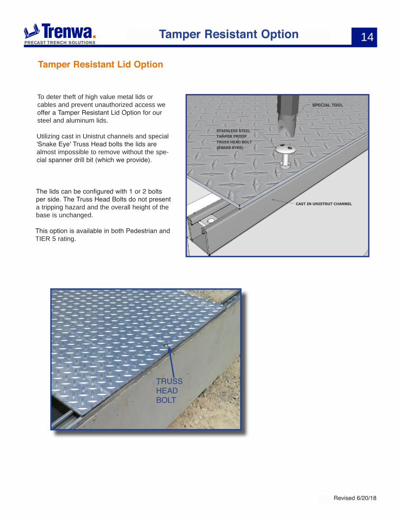
Tamper Resistant Lid Option
To deter theft of high value metal lids or cables and prevent unauthorized access we offer a Tamper Resistant Lid Option for our steel and aluminum lids.
Utilizing cast in Unistrut channels and special 'Snake Eye' Truss Head bolts the lids are almost impossible to remove without the spe-cial spanner drill bit (which we provide).
The lids can be configured with 1 or 2 bolts per side. The Truss Head Bolts do not present a tripping hazard and the overall height of the base is unchanged.
This option is available in both Pedestrian and TIER 5 rating.
Tamper Resistant Option
trusshead BOLt
15
Revised 6/20/18
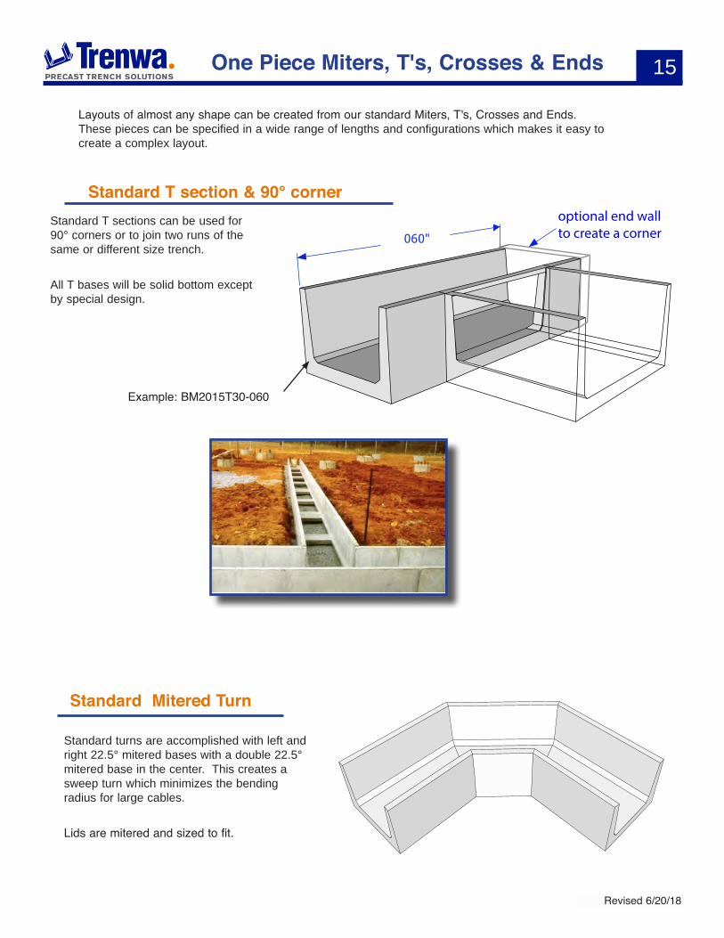
optional end wall to create a corner
Standard T section & 90° corner
One Piece Miters, T's, Crosses & Ends
Standard T sections can be used for 90° corners or to join two runs of the same or different size trench.
All T bases will be solid bottom except by special design.
Example: BM2015T30-060
Layouts of almost any shape can be created from our standard Miters, T's, Crosses and Ends. These pieces can be specified in a wide range of lengths and configurations which makes it easy to create a complex layout.
Standard Mitered Turn
Standard turns are accomplished with left and right 22.5° mitered bases with a double 22.5° mitered base in the center. This creates a sweep turn which minimizes the bending radius for large cables.
Lids are mitered and sized to fit.

16
Revised 6/20/18
60”
Standard Cross sections
Standard Cross sections are used when two runs need to cross each other. They can be same or different widths.
They are always solid bottom.
Example: BM2415X40-060
End Walls & Reducers
Standard End Walls are typically used to close off the end of a run. They can be held in place by backfill pressure or any elastomeric concrete adhesive.
Reducers are created by using 2 small end walls to block off the opening of the wider trench.
One Piece Miters, T's, Crosses & Ends
Example: WM2618-03
Example:WM1018-03
17
Revised 6/20/18
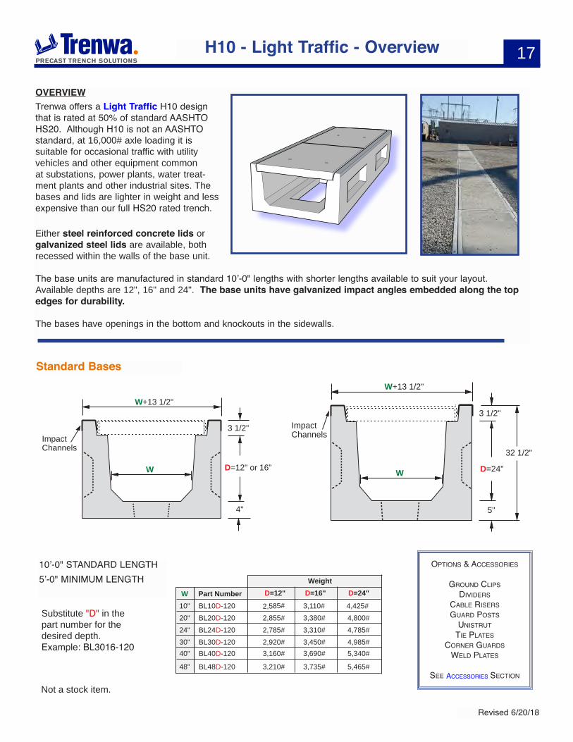
OVERVIEWTrenwa offers a Light Traffic H10 design that is rated at 50% of standard AASHTO HS20. Although H10 is not an AASHTO standard, at 16,000# axle loading it is suitable for occasional traffic with utility vehicles and other equipment common at substations, power plants, water treat-ment plants and other industrial sites. The bases and lids are lighter in weight and less expensive than our full HS20 rated trench.
Either steel reinforced concrete lids or galvanized steel lids are available, both recessed within the walls of the base unit.
The base units are manufactured in standard 10’-0" lengths with shorter lengths available to suit your layout. Available depths are 12", 16" and 24". The base units have galvanized impact angles embedded along the top edges for durability.
The bases have openings in the bottom and knockouts in the sidewalls.
H10 - Light Traffic - Overview
Standard Bases
W+13 1/2"
W
3 1/2"
D=12" or 16”
4"
ImpactChannels
W+13 1/2"
W
ImpactChannels
3 1/2"
D=24"
5"
32 1/2"
OPtiOns & aCCessOries
grOund CLiPs diViders
CaBLe risersguard POsts
unistruttie PLates
COrner guardsweLd PLates
see aCCessOries seCtiOn
10’-0" STANDARD LENGTH5’-0" MINIMUM LENGTH
Substitute "D" in the part number for the desired depth.Example: BL3016-120
Not a stock item.
D=16" D=24"Part NumberWWeight
BL10D-12010" 3,110# 4,425#BL20D-12020" 3,380# 4,800#BL24D-12024" 3,310# 4,785#BL30D-12030" 3,450# 4,985#BL40D-12040" 3,690# 5,340#
BL48D-12048" 3,735#
D=12"
2,585#2,855#2,785#2,920#3,160#
3,210# 5,465#
18
Revised 6/20/18
H10 - Light Traffic with Concrete Lid
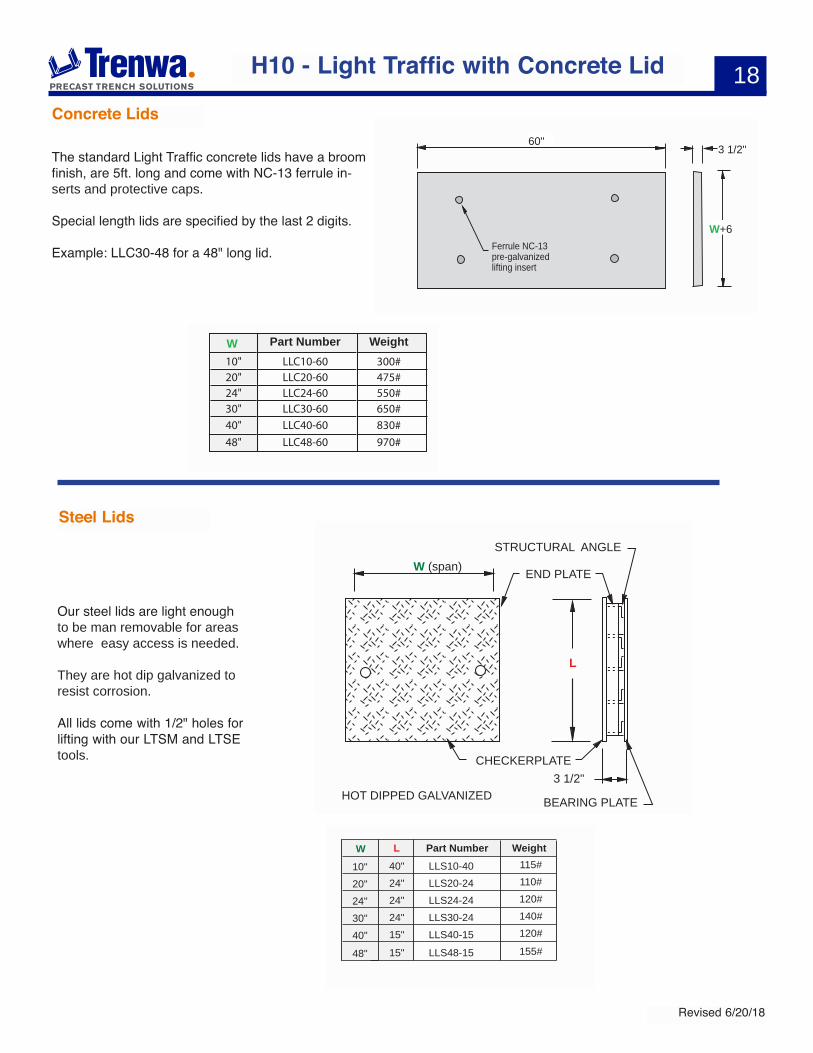
Concrete Lids
Steel Lids
3 1/2"
W+6Ferrule NC-13 pre-galvanizedlifting insert
60"
300#475#550#650#
830#
LLC10-60LLC20-60LLC24-60LLC30-60
LLC40-60
10"20"24"30"
40"
970#LLC48-6048"
Part NumberW Weight
The standard Light Traffic concrete lids have a broom finish, are 5ft. long and come with NC-13 ferrule in-serts and protective caps.
Special length lids are specified by the last 2 digits.
Example: LLC30-48 for a 48" long lid.
HOT DIPPED GALVANIZED
W (span)STRUCTURAL ANGLE
END PLATE
BEARING PLATE
CHECKERPLATE
L
3 1/2"
Part NumberW LLLS10-4010" 40" 115#
LLS20-2420" 24" 110#
LLS24-2424" 24" 120#
LLS30-2430" 24" 140#
LLS40-1540" 15" 120#
LLS48-1548" 15" 155#
Weight
Our steel lids are light enough to be man removable for areas where easy access is needed.
They are hot dip galvanized to resist corrosion.
All lids come with 1/2" holes for lifting with our LTSM and LTSE tools.
19
Revised 6/20/18
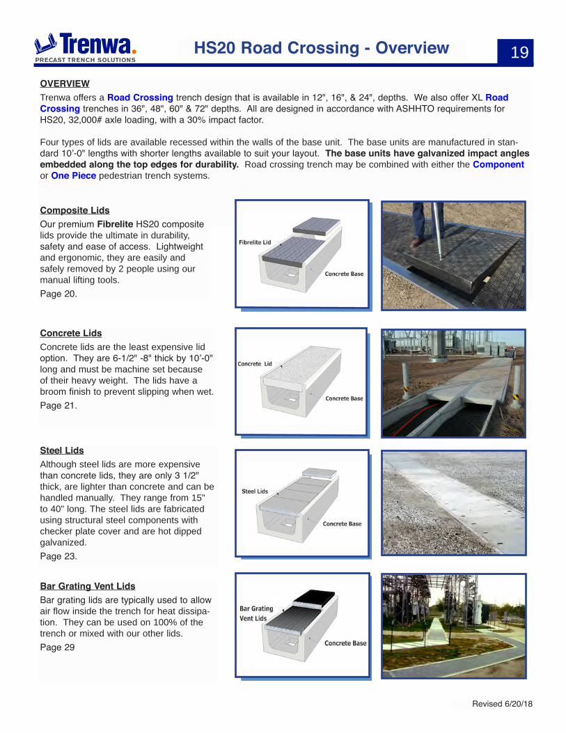
OVERVIEWTrenwa offers a Road Crossing trench design that is available in 12", 16", & 24", depths. We also offer XL Road Crossing trenches in 36", 48", 60" & 72" depths. All are designed in accordance with ASHHTO requirements for HS20, 32,000# axle loading, with a 30% impact factor.
Four types of lids are available recessed within the walls of the base unit. The base units are manufactured in stan-dard 10’-0" lengths with shorter lengths available to suit your layout. The base units have galvanized impact angles embedded along the top edges for durability. Road crossing trench may be combined with either the Component or One Piece pedestrian trench systems.
HS20 Road Crossing - Overview
Composite Lids Our premium Fibrelite HS20 composite lids provide the ultimate in durability, safety and ease of access. Lightweight and ergonomic, they are easily and safely removed by 2 people using our manual lifting tools.Page 20.
Concrete LidsConcrete lids are the least expensive lid option. They are 6-1/2" -8" thick by 10’-0" long and must be machine set because of their heavy weight. The lids have a broom finish to prevent slipping when wet. Page 21.
Bar Grating Vent Lids Bar grating lids are typically used to allow air flow inside the trench for heat dissipa-tion. They can be used on 100% of the trench or mixed with our other lids.Page 29
Steel Lids Although steel lids are more expensive than concrete lids, they are only 3 1/2" thick, are lighter than concrete and can be handled manually. They range from 15" to 40" long. The steel lids are fabricated using structural steel components with checker plate cover and are hot dipped galvanized. Page 23.
20
Revised 6/20/18
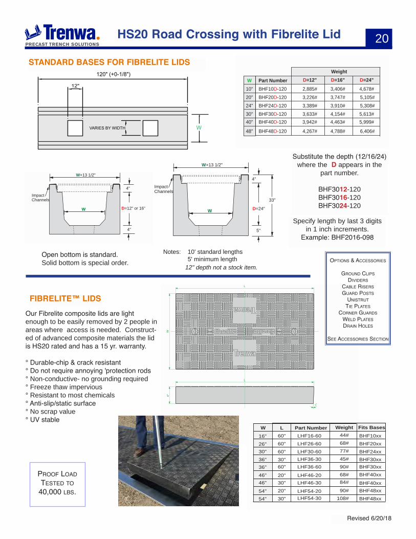
HS20 Road Crossing with Fibrelite Lid
D=16" D=24"Part NumberWWeight
BHF10D-12010" 3,406# 4,678#BHF20D-12020" 3,747# 5,105#BHF24D-12024" 3,910# 5,308#BHF30D-12030" 4,154# 5,613#BHF40D-12040" 4,463# 5,999#
BHF48D-12048" 4,788#
D=12"2,885#3,226#3,389#3,633#3,942#
4,267# 6,406#
W+13 1/2"
W
4"
D=12" or 16”
4"
ImpactChannels
Developed over 50 years ago by Trenwa - precast concrete trench is our specialty. With three modern, strategically located plants, we are the country’s leading producer of durable, precast trench systems in the broadest range of types and sizes.
1419 Alexandria PikeFort Thomas
KY 41075USA
Tel: +1 859 781 0831
Fax: +1 859 781 1085
Email: [email protected] - Tough Enough to Trust Page: 2 of 2www.trenwa.com
4"
L
L
W
W
SPAN = W - 6"(EXAMPLE 16" WIDTH - 6" = 10” SPAN)
W
HS20 TRENCH BASE
LHF16-60LHF26-60LHF30-60LHF36-30LHF36-60LHF46-20LHF46-30LHF54-20LHF54-30
COVERCODE
162630363646465454
W = WIDTH(INCHES)
606060306020302030
L = LENGTH(INCHES)
4468775090688490
108
WEIGHT(LBS)
1°
1°
• Lightweight composite construction
• Chip and crack resistant
• Freeze / thaw cycle impervious
• Non-conductive
• Chemically inert
• Exceeds service requirements
• 15 year warranty
• Anti-slip / anti-static surface
• Non-corrosive
• Custom colors available
• No scrap value
• Weather resistant
• Maintenance free
• UV stable
Part Number Fits BasesW LLHF16-6016" 60" 44#
LHF26-6026" 60" 68#
LHF30-6030" 60" 77#LHF36-3036" 30" 45#LHF36-6036" 60" 90#
LHF46-3046" 30" 84#LHF46-2046" 20" 68#
LHF54-20LHF54-30
54"54"
20"30"
90#108#
WeightBHF10xxBHF20xxBHF24xxBHF30xxBHF30xxBHF40xxBHF40xxBHF48xxBHF48xx
STANDARD BASES FOR FIBRELITE LIDS
FIBRELITE™ LIDS
W+13 1/2"
W
ImpactChannels
4"
D=24"
5"
33"
Notes: 10' standard lengths 5' minimum length OPtiOns & aCCessOries
grOund CLiPs diViders
CaBLe risersguard POsts
unistruttie PLates
COrner guardsweLd PLatesdrain hOLes
see aCCessOries seCtiOn
Open bottom is standard.Solid bottom is special order.
Our Fibrelite composite lids are light enough to be easily removed by 2 people in areas where access is needed. Construct-ed of advanced composite materials the lid is HS20 rated and has a 15 yr. warranty.
° Durable-chip & crack resistant° Do not require annoying 'protection rods° Non-conductive- no grounding required° Freeze thaw impervious° Resistant to most chemicals° Anti-slip/static surface° No scrap value° UV stable
Specify length by last 3 digits in 1 inch increments.
Example: BHF2016-098
PrOOF LOadtested tO
40,000 LBs.
12" depth not a stock item.
120" (+0-1/8")
12"
VARIES BY WIDTH W
Substitute the depth (12/16/24) where the D appears in the
part number.
BHF3012-120 BHF3016-120BHF3024-120
21
Revised 6/20/18
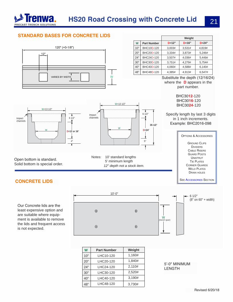
Our Concrete lids are the least expensive option and are suitable where equip-ment is available to remove the lids and frequent access is not expected.
HS20 Road Crossing with Concrete Lid
D=16" D=24"Part NumberWWeight
BHC10D-12010" 3,531# 4,819#BHC20D-12020" 3,873# 5,246#BHC24D-12024" 4,036# 5,449#BHC30D-12030" 4,279# 5,754#BHC40D-12040" 4,588# 6,140#
BHC48D-12048" 4,913#
D=12"3,003#3,334#3,507#3,751#4,060#
4,385# 6,547#
10'-0" 6 1/2"(8" on 60" + width)
W(trench span)
LHC10-120 1,160#
LHC20-120 1,840#
LHC24-120 2,110#
LHC30-120 2,520#
LHC40-120LHC48-120
3,190#
3,730#
10"20"24"30"40"48"
Part NumberW Weight
5’-0" MINIMUM LENGTH
STANDARD BASES FOR CONCRETE LIDS
CONCRETE LIDS
W+13 1/2"
W
6 1/2"
35 1/2"
D=24"
5"
Impact channels
W+13 1/2"
W
6 1/2"
D=12 or 16"
4"
Impact channels
OPtiOns & aCCessOries
grOund CLiPs diViders
CaBLe risersguard POsts
unistruttie PLates
COrner guardsweLd PLatesdrain hOLes
see aCCessOries seCtiOn
Specify length by last 3 digits in 1 inch increments.
Example: BHC2016-098
Open bottom is standard.Solid bottom is special order.
Notes: 10' standard lengths 5' minimum length
12" depth not a stock item.
120" (+0-1/8")
12"
VARIES BY WIDTH W Substitute the depth (12/16/24) where the D appears in the
part number.
BHC3012-120 BHC3016-120BHC3024-120
22
Revised 6/20/18
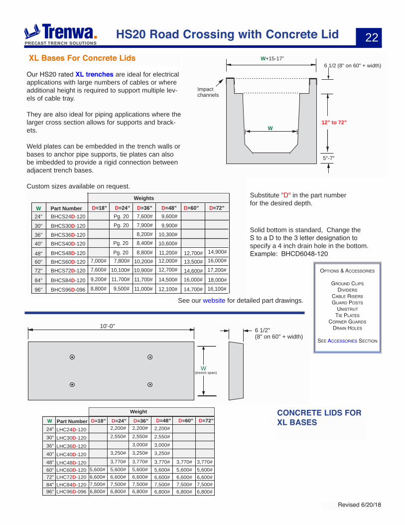
W+15-17”
W
6 1/2 (8" on 60" + width)
12” to 72”
5"-7"
Impact channels
BHCS36D-12036" 8,200#
BHCS24D-12024" 7,600#
11,200# 12,700#13,500#14,600#16,000#
16,100#18,000#
17,200#16,000#14,900#
14,700#
12,000#12,700#
14,500#12,100#
BHCS30D-12030" 7,900#
BHCS40D-12040" 8,400# 10,600#10,300#
9,900#9,600#
BHCS48D-120BHCS60D-120
48"60"
8,800# 10,200#
BHCS72D-12072" 10,900#
BHCS84D-12084" 11,700#
BHCS96D-09696" 11,000#
W
Weights
Part Number D=36”
7,000#
9,200#7,600#
8,800#
Pg. 20Pg. 20
Pg. 20Pg. 20
7,800#10,100#11,700#9,500#
D=24”D=18” D=48” D=60” D=72”
10'-0" 6 1/2"(8" on 60" + width)
W(trench span)
LHC24D-120 2,200#
LHC30D-120 2,550#
LHC36D-120 3,000#
LHC40D-120 3,250#
LHC48D-120LHC60D-120
3,770#5,600#5,600#6,600#7,500#6,800#
2,200#2,550#3,000#3,250#3,770#5,600#6,600#7,500#6,800#
W24"30"36"40"48"60"
LHC72D-12072"LHC84D-12084"LHC96D-09696"
Part Number D=36”
6,600#7,500#6,800#
D=18”
5,600#
2,200#2,550#
3,250#3,770#
6,600#7,500#6,800#
D=24” D=48”
3,770#5,600#6,600#7,500#6,800#
D=60”
3,770#5,600#6,600#7,500#6,800#
D=72”
Weight CONCRETE LIDS FOR XL BASES
Our HS20 rated XL trenches are ideal for electrical applications with large numbers of cables or where additional height is required to support multiple lev-els of cable tray.
They are also ideal for piping applications where the larger cross section allows for supports and brack-ets.
Weld plates can be embedded in the trench walls or bases to anchor pipe supports, tie plates can also be imbedded to provide a rigid connection between adjacent trench bases.
Custom sizes available on request.
HS20 Road Crossing with Concrete Lid
XL Bases For Concrete Lids
Substitute "D" in the part number for the desired depth.
OPtiOns & aCCessOries
grOund CLiPs diViders
CaBLe risersguard POsts
unistruttie PLates
COrner guardsdrain hOLes
see aCCessOries seCtiOn
Solid bottom is standard, Change the S to a D to the 3 letter designation to specify a 4 inch drain hole in the bottom. Example: BHCD6048-120
See our website for detailed part drawings.
23
Revised 6/20/18
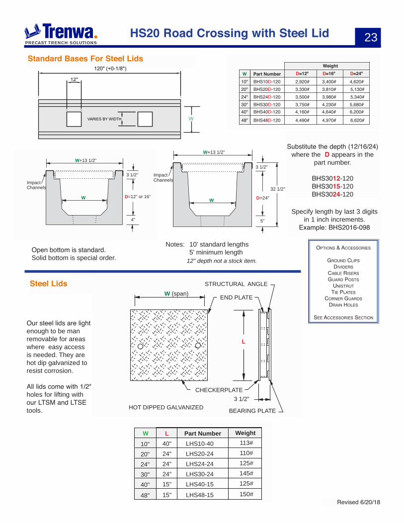
HS20 Road Crossing with Steel Lid
D=16" D=24"Part NumberW
Weight
BHS10D-12010" 3,400# 4,620#BHS20D-12020" 3,810# 5,130#BHS24D-12024" 3,980# 5,340#BHS30D-12030" 4,230# 5,680#BHS40D-12040" 4,640# 6,200#
BHS48D-12048" 4,970#
D=12"
2,920#3,330#3,500#3,750#4,160#
4,490# 6,620#
W+13 1/2"
W
3 1/2"
D=12" or 16”
4"
ImpactChannels
HOT DIPPED GALVANIZED
W (span)STRUCTURAL ANGLE
END PLATE
BEARING PLATE
CHECKERPLATE
L
3 1/2"
Part NumberW LLHS10-4010" 40" 113#
LHS20-2420" 24" 110#
LHS24-2424" 24" 125#
LHS30-2430" 24" 145#
LHS40-1540" 15" 125#
LHS48-1548" 15" 150#
Weight
Standard Bases For Steel Lids
Steel Lids
W+13 1/2"
W
ImpactChannels
3 1/2"
D=24"
5"
32 1/2"
Notes: 10' standard lengths 5' minimum length
OPtiOns & aCCessOries
grOund CLiPs diViders
CaBLe risersguard POsts
unistruttie PLates
COrner guardsdrain hOLes
see aCCessOries seCtiOn Our steel lids are light enough to be man removable for areas where easy access is needed. They are hot dip galvanized to resist corrosion.
All lids come with 1/2" holes for lifting with our LTSM and LTSE tools.
120" (+0-1/8")
12"
VARIES BY WIDTH W
Specify length by last 3 digits in 1 inch increments.
Example: BHS2016-098
Open bottom is standard.Solid bottom is special order. 12" depth not a stock item.
Substitute the depth (12/16/24) where the D appears in the
part number.
BHS3012-120 BHS3015-120BHS3024-120
24
Revised 6/20/18
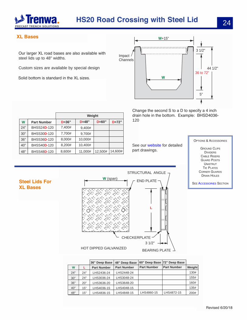
W+15"
W
ImpactChannels
3 1/2"
36 to 72"
5"
44 1/2"
Part NumberW
Weight
BHSS36D-12036" 8,000#
BHSS24D-12024" 7,400#
BHSS30D-12030" 7,700#
BHSS40D-12040" 8,200#
BHSS48D-12048" 8,600#
10,000#
9,400#9,700#
10,400#
11,000# 14,600#12,500#
D=36” D=48” D=60” D=72”
HOT DIPPED GALVANIZED
W (span)STRUCTURAL ANGLE
END PLATE
BEARING PLATE
CHECKERPLATE
L
3 1/2"
Part Number Part NumberW LLHS2436-2424" 24" 130#LHS3036-2430" 24" 155#LHS3636-2036" 20" 160#LHS4036-1540" 15" 135#LHS4836-15
LHS2448-24LHS3048-24LHS3648-20LHS4048-15LHS4848-1548" 15" 200#
Weight36" Deep Base 48" Deep Base
Part Number
LHS4860-15
60" Deep BasePart Number
LHS4872-15
72" Deep Base
Steel Lids For XL Bases
HS20 Road Crossing with Steel Lid
OPtiOns & aCCessOries
grOund CLiPs diViders
CaBLe risersguard POsts
unistruttie PLates
COrner guardsdrain hOLes
see aCCessOries seCtiOn
Change the second S to a D to specify a 4 inch drain hole in the bottom. Example: BHSD4036-120
Our larger XL road bases are also available with steel lids up to 48" widths.
Custom sizes are available by special design
See our website for detailed part drawings.
XL Bases
Solid bottom is standard in the XL sizes.
25
Revised 6/20/18
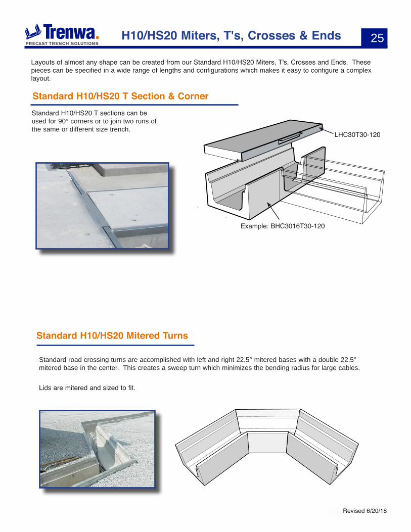
Standard H10/HS20 T Section & Corner
H10/HS20 Miters, T's, Crosses & Ends
Standard H10/HS20 T sections can be used for 90° corners or to join two runs of the same or different size trench.
Layouts of almost any shape can be created from our Standard H10/HS20 Miters, T's, Crosses and Ends. These pieces can be specified in a wide range of lengths and configurations which makes it easy to configure a complex layout.
Standard H10/HS20 Mitered Turns
Standard road crossing turns are accomplished with left and right 22.5° mitered bases with a double 22.5° mitered base in the center. This creates a sweep turn which minimizes the bending radius for large cables.
Lids are mitered and sized to fit.
Example: BHC3016T30-120
LHC30T30-120
26
Revised 6/20/18
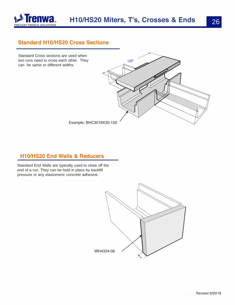
Standard H10/HS20 Cross Sections
Standard Cross sections are used when two runs need to cross each other. They can be same or different widths.
Example: BHC3016X30-120
H10/HS20 End Walls & ReducersStandard End Walls are typically used to close off the end of a run. They can be held in place by backfill pressure or any elastomeric concrete adhesive.
H10/HS20 Miters, T's, Crosses & Ends
WH4334-06
27
Revised 6/20/18
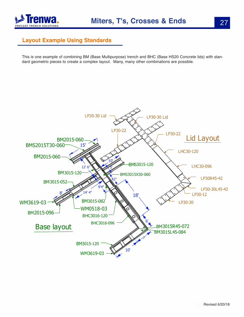
Layout Example Using Standards
Miters, T's, Crosses & Ends
WM3619-03
WM3619-03WM0518-03
BMS3015X30-060
BMS2015T30-060
BM
BM
BM
BM
BM
BM
BM
BM
BMBM
This is one example of combining BM (Base Multipurpose) trench and BHC (Base HS20 Concrete lids) with stan-dard geometric pieces to create a complex layout. Many, many other combinations are possible.
28
Revised 6/20/18
ENDWALLONE PIECE BASE
OPENING IN BASE
LID
OPEN
OPEN
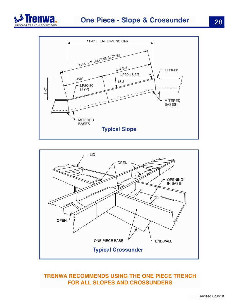
One Piece - Slope & Crossunder
TRENWA RECOMMENDS USING THE ONE PIECE TRENCH FOR ALL SLOPES AND CROSSUNDERS
3'-0
"11'-0" (FLAT DIMENSION)
5'-0"
11'-4 3/4" (ALONG SLOPE)
MITERED BASES
MITERED BASES
LP20-16 3/8LP20-08
LP20-30 (TYP)
6'-4 3/4"
15.3°
EXAMPLE
TRENWA RECOMMENDS USING THE ONE PIECE SYSTEM FOR SLOPES
Typical Slope
Typical Crossunder
29
Revised 6/20/18
Ventilator Lids
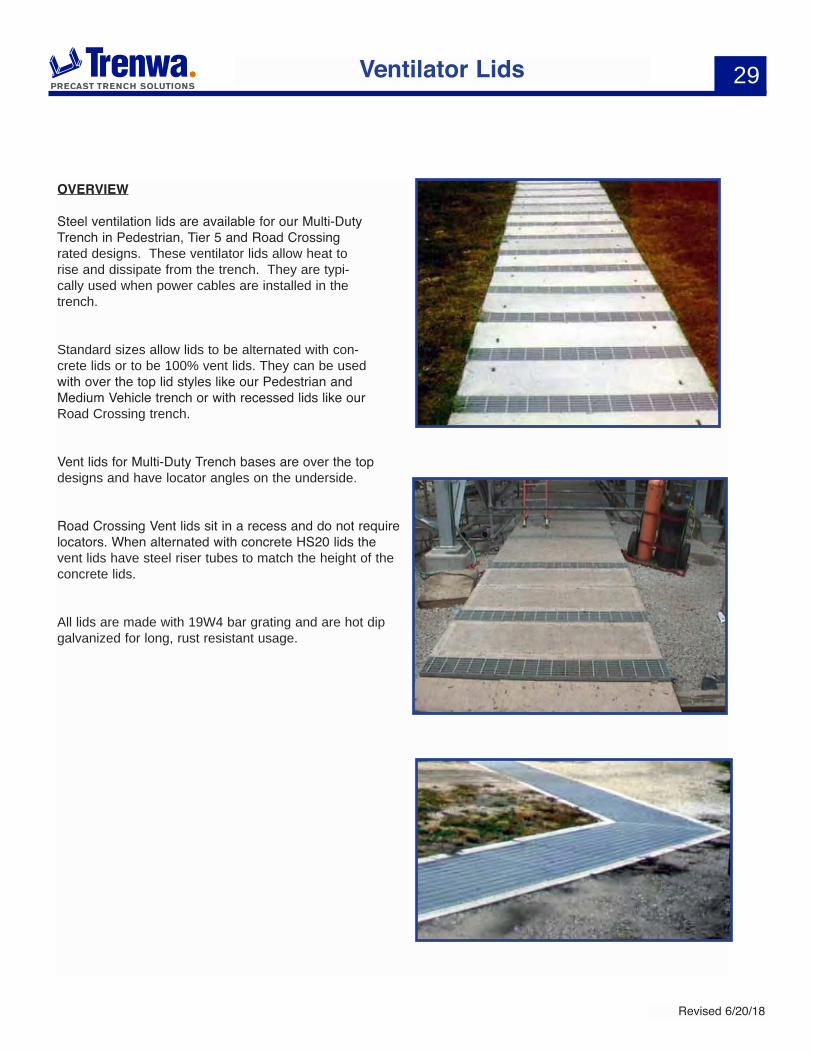
OVERVIEW
Steel ventilation lids are available for our Multi-Duty Trench in Pedestrian, Tier 5 and Road Crossing rated designs. These ventilator lids allow heat to rise and dissipate from the trench. They are typi-cally used when power cables are installed in the trench.
Standard sizes allow lids to be alternated with con-crete lids or to be 100% vent lids. They can be used with over the top lid styles like our Pedestrian and Medium Vehicle trench or with recessed lids like our Road Crossing trench.
Vent lids for Multi-Duty Trench bases are over the top designs and have locator angles on the underside.
Road Crossing Vent lids sit in a recess and do not require locators. When alternated with concrete HS20 lids the vent lids have steel riser tubes to match the height of the concrete lids.
All lids are made with 19W4 bar grating and are hot dip galvanized for long, rust resistant usage.
30
Revised 6/20/18
Galvanized Steel Vent Lids
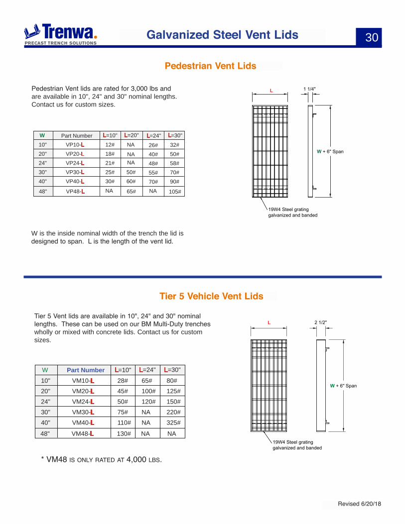
Tier 5 Vehicle Vent Lids
Part NumberW L=10" L=24"VM10-L10" 28# 65#VM20-L20" 45# 100#VM24-L24" 50# 120#VM30-L30" 75# NAVM40-L40" 110# NA
L=30"80#125#150#220#325#
VM48-L48" 130# NA NA
W + 6" Span
2 1/2"
19W4 Steel gratinggalvanized and banded
L Tier 5 Vent lids are available in 10", 24" and 30" nominal lengths. These can be used on our BM Multi-Duty trenches wholly or mixed with concrete lids. Contact us for custom sizes.
Part NumberW L=10" L=20"VP10-L10" 12# NA
NANA
NA NA
VP20-L20" 18#VP24-L24" 21#VP30-L30" 25# 50#VP40-L40" 30# 60#
L=30"32#50#58#70#90#
VP48-L48" 65#
L=24"26#40#48#55#70#
105#
Pedestrian Vent Lids
Pedestrian Vent lids are rated for 3,000 lbs and are available in 10", 24" and 30" nominal lengths. Contact us for custom sizes.
W is the inside nominal width of the trench the lid is designed to span. L is the length of the vent lid.
W + 6" Span
L 1 1/4"
19W4 Steel gratinggalvanized and banded
* VM48 is OnLy rated at 4,000 LBs.

31
Revised 6/20/18
HS20 Road Crossing Vent Lids
Part NumberW L=10" L=24"VHS10-L10" 40# 90#VHS20-L20" 60# 145#VHS24-L24" 70# 168#VHS30-L30" 85# 200#VHS40-L40" 105# 253#
L=30"113#180#208#250#315#
VHS48-L48" 135# 300# 400#
W + 6 1/2" Span
3 1/2" L
19W4 Steel gratinggalvanized and banded
HS20 Vent lids are rated at 32,000#/axle and are available in 10", 24" and 30" nominal lengths. These can be used on our BHS and BHC series trenches wholly or mixed with concrete lids. Contact us for custom sizes
Galvanized Steel Vent Lids
The following vent lid models are designed for a 3 1/2" recess and will fit our BHS series road bases. They should be used where 100% vent lid coverage is desired or mixed with steel lids.
Part NumberW L=10" L=24" L=30"VHC10-L10" 46# 100#VHC20-L20" 70# 165#VHC24-L24" 80# 185#VHC30-L30" 92# 220#VHC40-L40" 115# 275#
125#208#235#275#345#
VHC48-L48" 125# 345# 375#
W + 7" Span
3 1/2"
L
3"
Riser tube19W4 Steel gratinggalvanized and banded
6 1/2"
The following vent lid models are designed for a 6 1/2" recess and will fit our BHC series road bases. They should be used when mixed with concrete lids.
• Overview - 34• Lids & Brackets - 35
• Side Walls & End Walls - 36• Tees, Crosses, Reducers - 37
• 90° & Mitered Turns - 38
Trenwaphone: 859-781-0831 fax: 859-781-1085
e-mail: [email protected]
1419 Alexandria PikeFt. Thomas, KY 41075
www.trenwa.com
COmPOnenT TrenCh
34
Revised 6/20/18
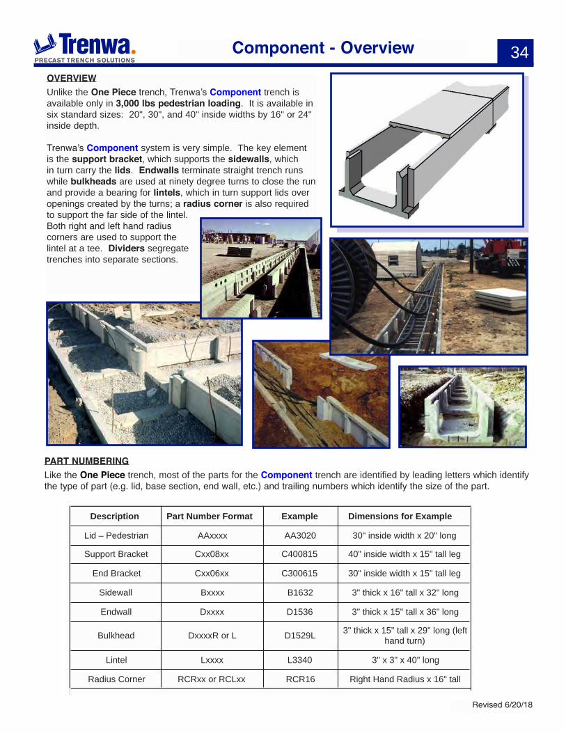
OVERVIEWUnlike the One Piece trench, Trenwa’s Component trench is available only in 3,000 lbs pedestrian loading. It is available in six standard sizes: 20", 30", and 40" inside widths by 16" or 24" inside depth.
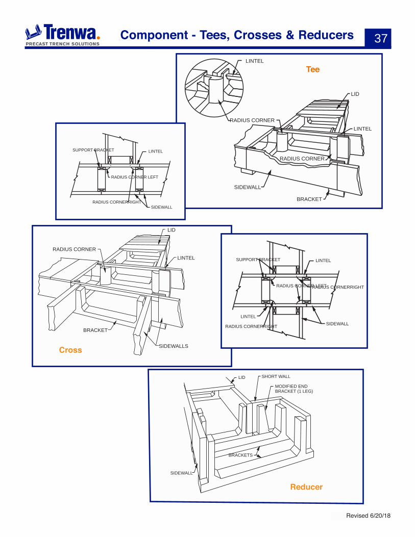
Trenwa’s Component system is very simple. The key element is the support bracket, which supports the sidewalls, which in turn carry the lids. Endwalls terminate straight trench runs while bulkheads are used at ninety degree turns to close the run and provide a bearing for lintels, which in turn support lids over openings created by the turns; a radius corner is also required to support the far side of the lintel. Both right and left hand radius corners are used to support the lintel at a tee. Dividers segregate trenches into separate sections.
PART NUMBERINGLike the One Piece trench, most of the parts for the Component trench are identified by leading letters which identify the type of part (e.g. lid, base section, end wall, etc.) and trailing numbers which identify the size of the part.
Component - Overview
Description Part Number Format Example Dimensions for Example
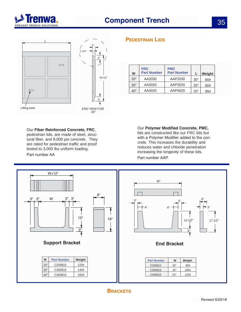
Lid – Pedestrian AAxxxx AA3020 30" inside width x 20" long
Support Bracket Cxx08xx C400815 40" inside width x 15" tall leg
End Bracket Cxx06xx C300615 30" inside width x 15" tall leg
Sidewall Bxxxx B1632 3" thick x 16" tall x 32" long
Endwall Dxxxx D1536 3" thick x 15" tall x 36" long
Bulkhead DxxxxR or L D1529L 3" thick x 15" tall x 29" long (left hand turn)
Lintel Lxxxx L3340 3" x 3" x 40" long
Radius Corner RCRxx or RCLxx RCR16 Right Hand Radius x 16" tall
35
Revised 6/20/18
W 3" 3"3" 3"8"
W+12"
3"
15" 18"
Part NumberW WeightC20081520" 120#C30081530" 140#C40081540" 160#
3"
W"
3"
4" 4"
3"
3"
6"
14 1/2" 17 1/2"
Part Number W WeightC200615 32" 90#C300615 42" 105#C400615 52" 120#
End BracketSupport Bracket
Component Trench
L
Lifting slots
2"
1 1/4"
3"
3"
W+12"
END VIEW FOR 20"
FRCPart NumberW L Weight
AA203020" 30" 80#AA3020 AAP302030" 20" 80#AA4020
PMCPart Number
AAP2030
AAP402040" 20" 95#
PedesTrian lids
braCkeTs
Our Fiber Reinforced Concrete, FRC, pedestrian lids, are made of steel, struc-tural fiber, and 8,000 psi concrete. They are rated for pedestrian traffic and proof tested to 3,000 lbs uniform loading. Part number AA
Our Polymer Modified Concrete, PMC, lids are constructed like our FRC lids but with a Polymer Modifier added to the con-crete. This increases the durability and reduces water and chloride penetration increasing the longevity of these lids. Part number AAP.
36
Revised 6/20/18
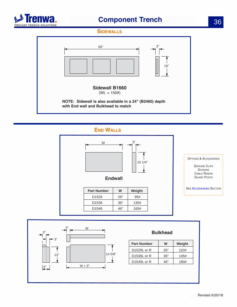
60" 3"
16"
NOTE: Sidewall is also available in a 24" (B2460) depth with End wall and Bulkhead to match
Sidewall B1660(Wt. = 150#)
Endwall
Part Number W WeightD1526 26" 95#D1536 36" 130#D1546 46" 165#
13"
3"W
14 5/8"
3"
6" W + 3"
3"Bulkhead
Part Number W Weight
D1529L or R 26" 110#D1539L or R 36" 145#D1549L or R 46" 180#
15 1/4"
3"W
Component Trench
OPtiOns & aCCessOries
grOund CLiPs diViders
CaBLe risersguard POsts
see aCCessOries seCtiOn
sidewalls
end walls
37
Revised 6/20/18
Component - Tees, Crosses & Reducers
SIDEWALL
BRACKET
LID
LINTEL
RADIUS CORNER
RADIUS CORNER
LINTEL
RADIUS CORNER LEFT
RADIUS CORNERRIGHT
LINTEL
SIDEWALL
SUPPORT BRACKET
RADIUS CORNER
LID
LINTEL
BRACKET
SIDEWALLS
Tee
Cross
RADIUS CORNER LEFTRADIUS CORNERRIGHT
LINTEL
SIDEWALL
SUPPORT BRACKET
RADIUS CORNERRIGHT
LINTEL
MODIFIED END BRACKET (1 LEG)
SHORT WALLLID
SIDEWALL
BRACKETS
Reducer
38
Revised 6/20/18
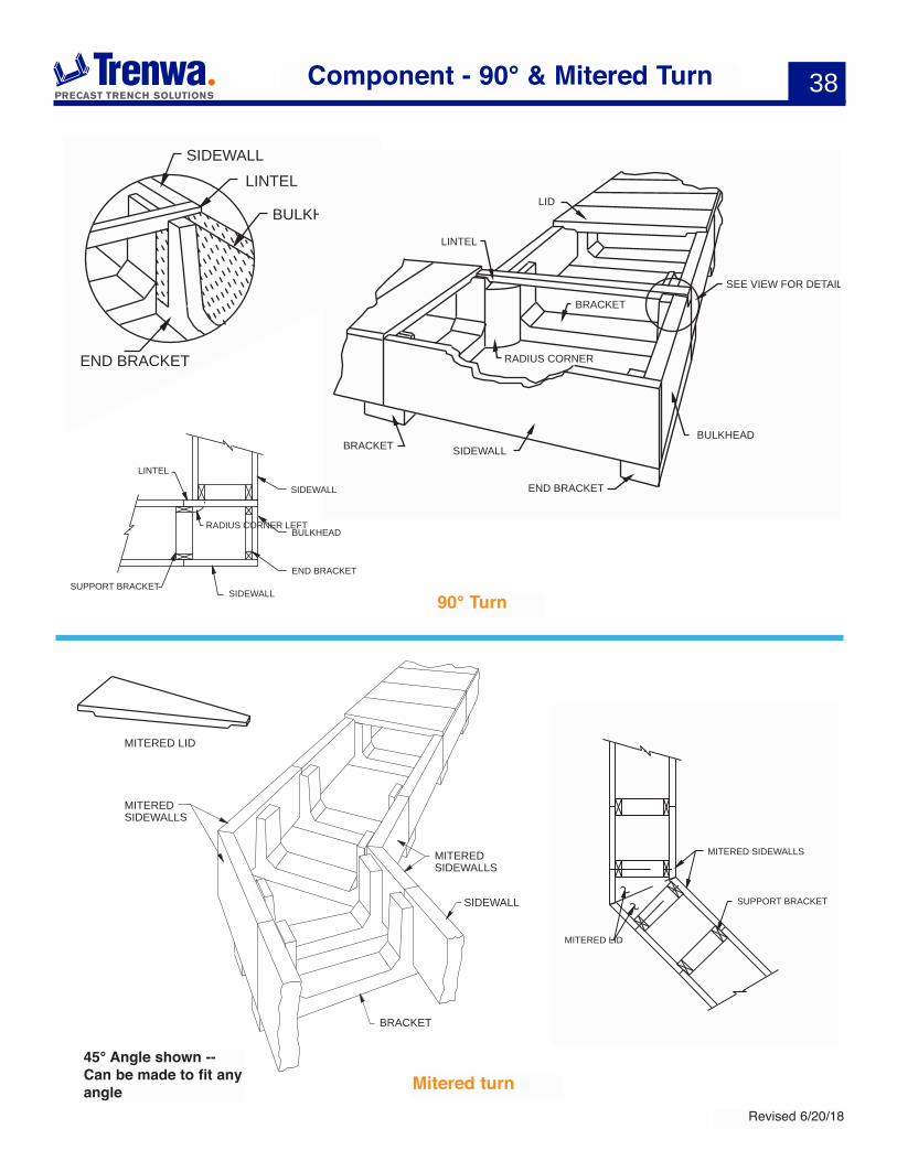
Component - 90° & Mitered Turn
LINTEL
RADIUS CORNER
BRACKET
BULKHEAD
END BRACKET
SIDEWALLBRACKET
LID
SEE VIEW FOR DETAILS
RADIUS CORNER LEFT
LINTEL
SUPPORT BRACKETEND BRACKET
BULKHEAD
SIDEWALL
SIDEWALL
SIDEWALLLINTEL
END BRACKET
BULKHEAD
MITERED LID
MITERED SIDEWALLS
SUPPORT BRACKET
MITEREDSIDEWALLS
SIDEWALL
BRACKET
MITERED SIDEWALLS
MITERED LID
90° Turn
Mitered turn45° Angle shown -- Can be made to fit any angle

Trenwaphone: 859-781-0831 fax: 859-781-1085
e-mail: [email protected]
1419 Alexandria PikeFt. Thomas, KY 41075
www.trenwa.com
• Dividers, Unistrut, Weld Plates - 41• Cable Clips, Innerduct, Guard Posts - 42
Cable Management- 43• Power Accessories - 44
• Tie Plates - 45• Sealant, Corner Guards, Drain Holes - 46
• Cable Risers - 47• Cross Drains - 48• Lifting Tools - 49
aCCessOries
41
Revised 6/20/18
Accessories
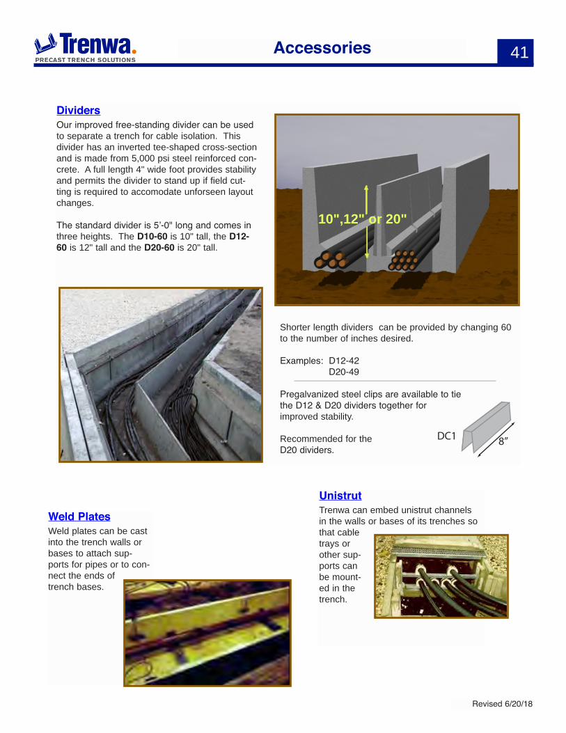
DividersOur improved free-standing divider can be used to separate a trench for cable isolation. This divider has an inverted tee-shaped cross-section and is made from 5,000 psi steel reinforced con-crete. A full length 4" wide foot provides stability and permits the divider to stand up if field cut-ting is required to accomodate unforseen layout changes.
The standard divider is 5’-0" long and comes in three heights. The D10-60 is 10" tall, the D12-60 is 12" tall and the D20-60 is 20" tall.
Shorter length dividers can be provided by changing 60 to the number of inches desired.
Examples: D12-42 D20-49
Pregalvanized steel clips are available to tie the D12 & D20 dividers together for improved stability.
Recommended for the D20 dividers.
UnistrutTrenwa can embed unistrut channels in the walls or bases of its trenches so that cable trays or other sup-ports can be mount-ed in the trench.
Weld PlatesWeld plates can be cast into the trench walls or bases to attach sup-ports for pipes or to con-nect the ends of trench bases.
10",12" or 20"
8’’DC1
42
Revised 6/20/18
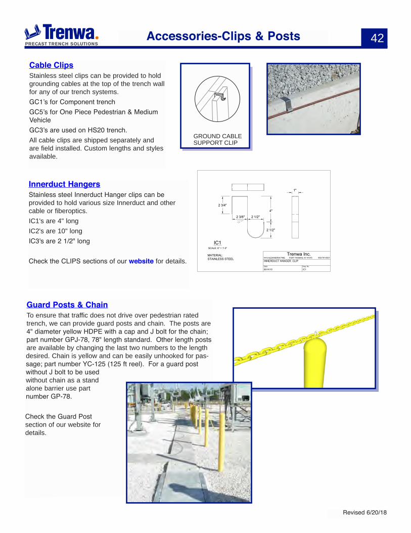
Cable ClipsStainless steel clips can be provided to hold grounding cables at the top of the trench wall for any of our trench systems. GC1’s for Component trenchGC5’s for One Piece Pedestrian & Medium VehicleGC3’s are used on HS20 trench. All cable clips are shipped separately and are field installed. Custom lengths and styles available.
Innerduct HangersStainless steel Innerduct Hanger clips can be provided to hold various size Innerduct and other cable or fiberoptics.IC1's are 4" longIC2's are 10" longIC3's are 2 1/2" long
Check the CLIPS sections of our website for details.
GROUND CABLE SUPPORT CLIP
Guard Posts & ChainTo ensure that traffic does not drive over pedestrian rated trench, we can provide guard posts and chain. The posts are 4" diameter yellow HDPE with a cap and J bolt for the chain; part number GPJ-78, 78" length standard. Other length posts are available by changing the last two numbers to the length desired. Chain is yellow and can be easily unhooked for pas-sage; part number YC-125 (125 ft reel). For a guard post without J bolt to be used without chain as a stand alone barrier use part number GP-78.
Check the Guard Post section of our website for details.
IC1SCALE: 6" = 1'-0"
2 3/4"
2 3/8"+1/16"-0"
1"
4"
MATERIAL:STAINLESS STEEL
2 1/2"
2 1/2"
Trenwa Inc.FORT THOMAS, KY 410751419 ALEXANDRIA PIKE 859-781-0831
Date: Dwg. No.
IC1
INNERDUCT HANGER CLIP
06/14/10
Accessories-Clips & Posts

43
Revised 6/20/18
Cable ManagementUnderground Devices cable management systems is an elegant and flexible method for organizing cables and maximizing the space in your trench. The cable arms allow for separation of the cables and utilizes the space on the trench walls leaving the floor free for access or additional cables.
The cable arms come in a variety of styles and sizes and can be surface mounted with expansion anchors in the field or we can cast Unistrut into the side walls which allows you to quickly attach them with bolts saving considerable installation time. See our website for more information and product specific catalogs.
Accessories-Cable Management
44
Revised 6/20/18
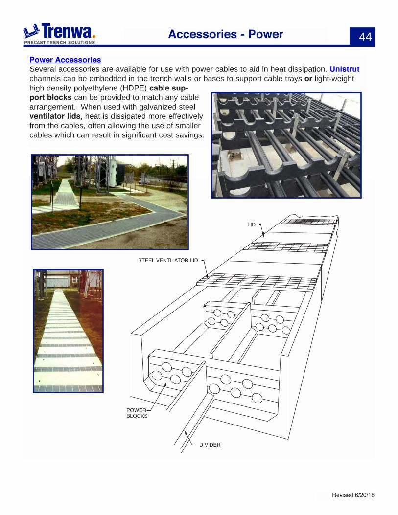
LID
STEEL VENTILATOR LID
DIVIDER
POWERBLOCKS
Accessories - Power
Power AccessoriesSeveral accessories are available for use with power cables to aid in heat dissipation. Unistrut channels can be embedded in the trench walls or bases to support cable trays or light-weight high density polyethylene (HDPE) cable sup-port blocks can be provided to match any cable arrangement. When used with galvanized steel ventilator lids, heat is dissipated more effectively from the cables, often allowing the use of smaller cables which can result in significant cost savings.
45
Revised 6/20/18
Accessories - Tie Plates & Sealant
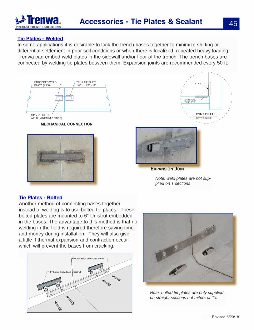
Tie Plates - WeldedIn some applications it is desirable to lock the trench bases together to minimize shifting ordifferential settlement in poor soil conditions or when there is localized, repeated heavy loading. Trenwa can embed weld plates in the sidewall and/or floor of the trench. The trench bases are connected by welding tie plates between them. Expansion joints are recommended every 50 ft.
MECHANICAL CONNECTION
EMBEDDED WELD PLATE (4 X 6)
1/4" x 2" FILLETWELD (MINIMUM 2 SIDES)
TP-12 TIE PLATE1/4" x 1 1/2" x 12"
NOT TO SCALE
JOINT DETAIL
EMBEDDEDTIE PLATE
TP-D02
Tie Plates - BoltedAnother method of connecting bases together instead of welding is to use bolted tie plates. These bolted plates are mounted to 6" Unistrut embedded in the bases. The advantage to this method is that no welding in the field is required therefore saving time and money during installation. They will also give a little if thermal expansion and contraction occur which will prevent the bases from cracking.
Note: bolted tie plates are only supplied on straight sections not miters or T's
Note: weld plates are not sup-plied on T sections
exPansiOn JOinT
Flat bar with oversized holes
6" Long Embedded Unistrut
46
Revised 6/20/18
Corner GuardsFor cable applications we will supply our Corner Guards on T's, Crosses, and 90 degree turns to protect cables from abrasion. They typically come partially installed with drive nail anchors to complete the other side.
They are available in the following sizes:
CG-09 for trenches 10-12 inches deepCG-12 for trenches 15-16 inches deepCG-20 for trenches 24 inches deep
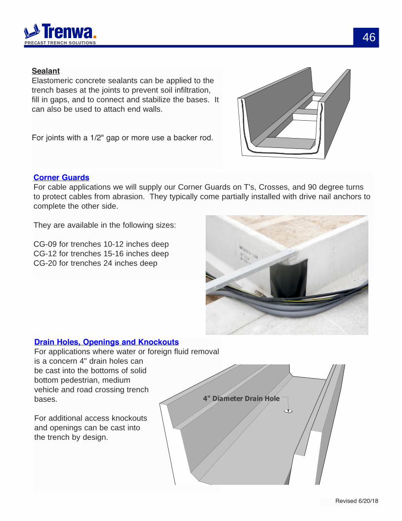
Drain Holes, Openings and KnockoutsFor applications where water or foreign fluid removal is a concern 4" drain holes can be cast into the bottoms of solid bottom pedestrian, medium vehicle and road crossing trench bases.
For additional access knockouts and openings can be cast into the trench by design.
SealantElastomeric concrete sealants can be applied to the trench bases at the joints to prevent soil infiltration, fill in gaps, and to connect and stabilize the bases. It can also be used to attach end walls.
For joints with a 1/2" gap or more use a backer rod.
4" Diameter Drain Hole
47
Revised 6/20/18
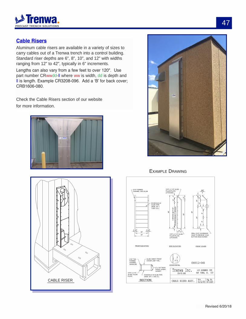
CABLE RISER
Cable RisersAluminum cable risers are available in a variety of sizes to carry cables out of a Trenwa trench into a control building. Standard riser depths are 6", 8", 10", and 12" with widths ranging from 12" to 42", typically in 6" increments. Lengths can also vary from a few feet to over 120". Use part number CRwwdd-ll where ww is width, dd is depth and ll is length. Example CR3208-096. Add a ‘B’ for back cover; CRB1606-080.
Check the Cable Risers section of our website for more information.
3/16" THK.FORMEDCHANNEL3003ALUM.
ALUM. SHEET FRONTCOVER (.080" THK.)
2" x 1/8" THICKFRONT & REARGASKET
3/16" x 2 1/4"ALUM. FILLERPLATE
SCHEDULE 40 ALUM. PIPE(NOM. 3/4" x 1.050 .D.)
COVER DETAIL
1"
FRONT COVER
.080"
1"
12"
4"
DRILL 5/16" CLEARANCE HOLE TO RECEIVE 1/4-20 BUTTON HEAD SCREW
48"
24"
12"
8"4"
24"
8"
2"3"
4 R
UN
GS
EQU
ALLY
SPA
CED
3/16" x 2 1/2" ALUM. FILLER PLATE(2 PLACES)
3/16" x 2 1/2" ALUM. FILLER PLATE(2 PLACES)
48"
12"
SIDE ELEVATION
12"
3 SP
ACES
@ 9
"=45
"12
"
48"
2 1/2" 2 1/2"
3/16" FORMEDCHANNEL 3003 ALUM.
SCHEDULE 40ALUM. PIPE(NOM. 3/4" x1.050" O.D.)
FRONT ELEVATION
30"
35"
SECTION
exaMPLe drawing
48
Revised 6/20/18
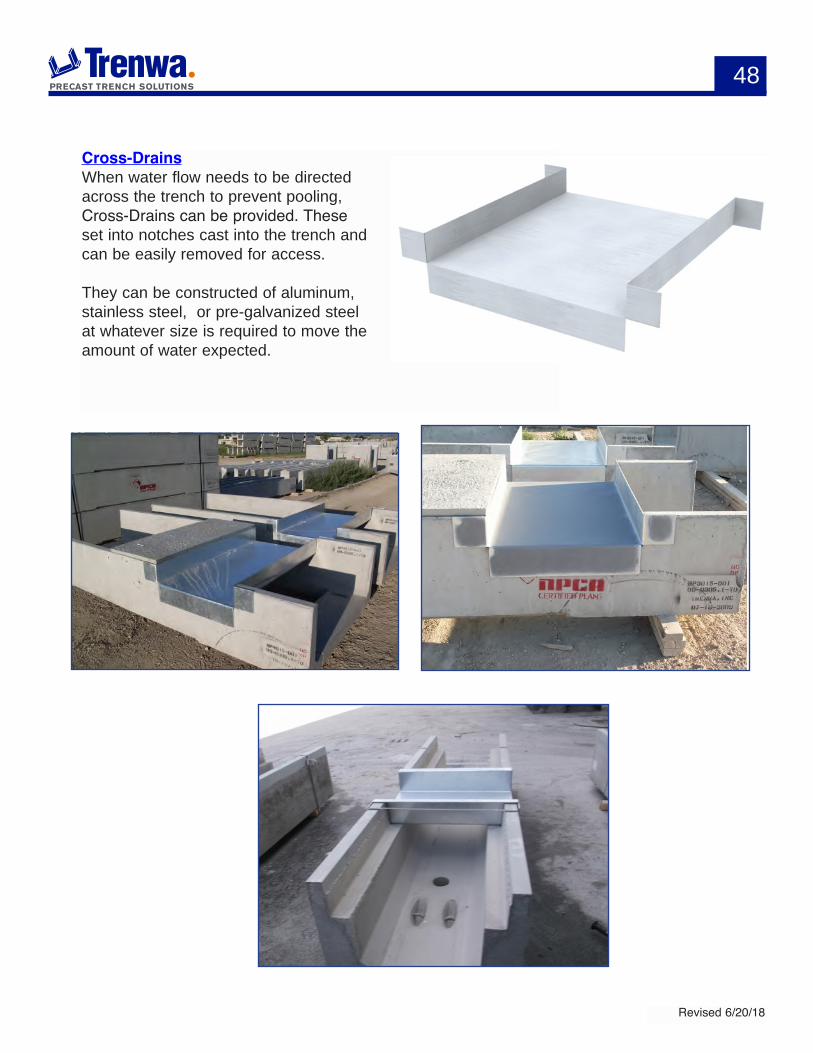
Cross-DrainsWhen water flow needs to be directed across the trench to prevent pooling, Cross-Drains can be provided. These set into notches cast into the trench and can be easily removed for access.
They can be constructed of aluminum, stainless steel, or pre-galvanized steel at whatever size is required to move the amount of water expected.
49
Revised 6/20/18
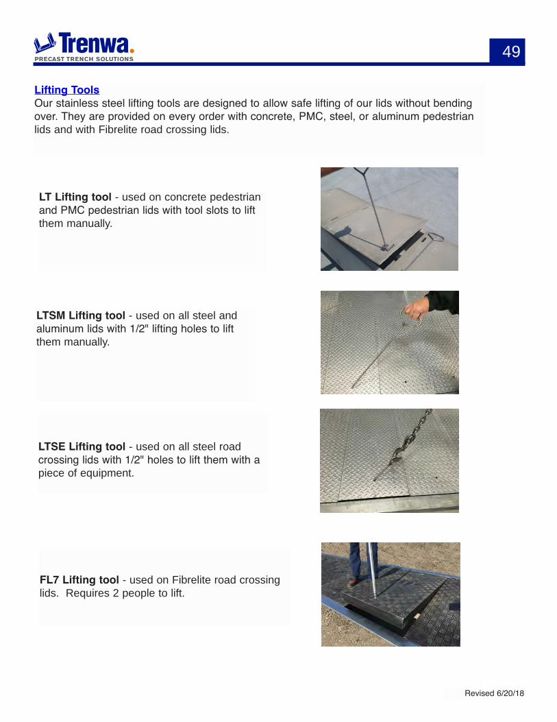
Lifting ToolsOur stainless steel lifting tools are designed to allow safe lifting of our lids without bending over. They are provided on every order with concrete, PMC, steel, or aluminum pedestrian lids and with Fibrelite road crossing lids.
LT Lifting tool - used on concrete pedestrian and PMC pedestrian lids with tool slots to lift them manually.
LTSM Lifting tool - used on all steel and aluminum lids with 1/2" lifting holes to lift them manually.
LTSE Lifting tool - used on all steel road crossing lids with 1/2" holes to lift them with a piece of equipment.
FL7 Lifting tool - used on Fibrelite road crossing lids. Requires 2 people to lift.

Trenwaphone: 859-781-0831 fax: 859-781-1085
e-mail: [email protected]
1419 Alexandria PikeFt. Thomas, KY 41075
www.trenwa.com
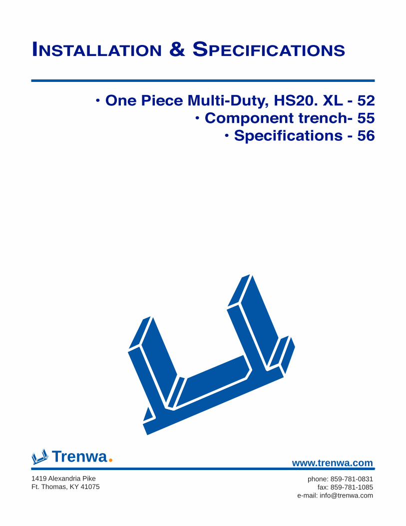
• One Piece Multi-Duty, HS20. XL - 52• Component trench- 55
• Specifications - 56
insTallaTiOn & sPeCifiCaTiOns
52
Revised 6/20/18
One Piece Multi-Duty, HS20 & XL
Unloading & StorageTo reduce the risk of damage, care should be taken in unloading and storing trench material. All material should be stored on level ground. Dunnage should be placed under all bases and road crossing covers. In addition, the dunnage should be placed vertically in-line with underlying dunnage as additional pieces are placed on each stack of mate-rial.
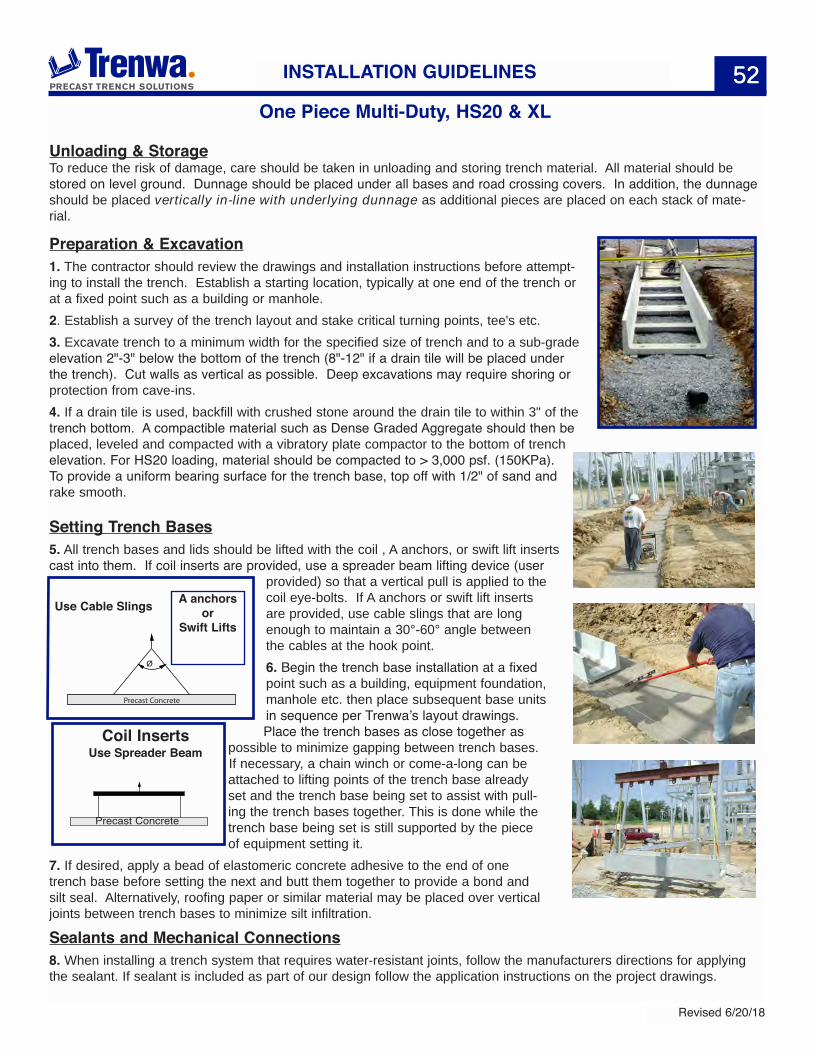
Preparation & Excavation1. The contractor should review the drawings and installation instructions before attempt-ing to install the trench. Establish a starting location, typically at one end of the trench or at a fixed point such as a building or manhole.2. Establish a survey of the trench layout and stake critical turning points, tee's etc.3. Excavate trench to a minimum width for the specified size of trench and to a sub-grade elevation 2"-3" below the bottom of the trench (8"-12" if a drain tile will be placed under the trench). Cut walls as vertical as possible. Deep excavations may require shoring or protection from cave-ins.4. If a drain tile is used, backfill with crushed stone around the drain tile to within 3" of the trench bottom. A compactible material such as Dense Graded Aggregate should then be placed, leveled and compacted with a vibratory plate compactor to the bottom of trench elevation. For HS20 loading, material should be compacted to > 3,000 psf. (150KPa). To provide a uniform bearing surface for the trench base, top off with 1/2" of sand and rake smooth.
Setting Trench Bases5. All trench bases and lids should be lifted with the coil , A anchors, or swift lift inserts cast into them. If coil inserts are provided, use a spreader beam lifting device (user
provided) so that a vertical pull is applied to the coil eye-bolts. If A anchors or swift lift inserts are provided, use cable slings that are long enough to maintain a 30°-60° angle between the cables at the hook point.6. Begin the trench base installation at a fixed point such as a building, equipment foundation, manhole etc. then place subsequent base units in sequence per Trenwa’s layout drawings. Place the trench bases as close together as
possible to minimize gapping between trench bases. If necessary, a chain winch or come-a-long can be attached to lifting points of the trench base already set and the trench base being set to assist with pull-ing the trench bases together. This is done while the trench base being set is still supported by the piece of equipment setting it.
7. If desired, apply a bead of elastomeric concrete adhesive to the end of one trench base before setting the next and butt them together to provide a bond and silt seal. Alternatively, roofing paper or similar material may be placed over vertical joints between trench bases to minimize silt infiltration.
Sealants and Mechanical Connections8. When installing a trench system that requires water-resistant joints, follow the manufacturers directions for applying the sealant. If sealant is included as part of our design follow the application instructions on the project drawings.
Ø
Precast Concrete
Use Cable Slings A anchorsor
Swift Lifts
52INSTALLATION GUIDELINES
Use Spreader BeamCoil Inserts
Precast Concrete
53
Revised 6/20/18
53
Some installations require a joint sealant material that is applied to the exterior of the base units overlapping the joint. Apply this type sealant material after the base units have been securely set.9. If a mechanical connection is specified to join the base units, weld the Trenwa supplied steel tie-plate to the weld plates which are embedded in the end of the walls of adjacent bases. Do this after the bases have been securely set and pulled together. Weld the tie-plates prior to removing the chain winch or come-a–long. All exposed weld plates should be treated with a rust inhibitor coating after welding is completed and the trench is securely in place.10. After setting two to three bases it is important to “continually” check the distance between the last trench base set and the next turning point, tee, etc. If an adjustment needs to be made in the trench base spacing it can be done over several trench bases to minimize the severity of the adjustment.
Backfilling11. Backfilling should be done with sand or gravel and firmly compacted to the compac-tion specified in Step 3. The backfill can be topped off with excavated soils. A flowable grout may be used as an alternative to a granular backfill material so that it fills any voids between the bases and the backfill material.
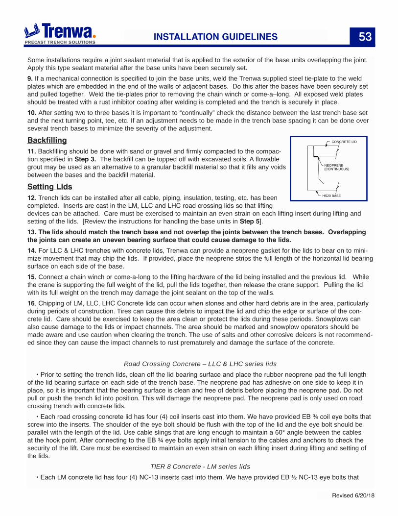
Setting Lids12. Trench lids can be installed after all cable, piping, insulation, testing, etc. has been completed. Inserts are cast in the LM, LLC and LHC road crossing lids so that lifting devices can be attached. Care must be exercised to maintain an even strain on each lifting insert during lifting and setting of the lids. [Review the instructions for handling the base units in Step 5].13. The lids should match the trench base and not overlap the joints between the trench bases. Overlapping the joints can create an uneven bearing surface that could cause damage to the lids.14. For LLC & LHC trenches with concrete lids, Trenwa can provide a neoprene gasket for the lids to bear on to mini-mize movement that may chip the lids. If provided, place the neoprene strips the full length of the horizontal lid bearing surface on each side of the base. 15. Connect a chain winch or come-a-long to the lifting hardware of the lid being installed and the previous lid. While the crane is supporting the full weight of the lid, pull the lids together, then release the crane support. Pulling the lid with its full weight on the trench may damage the joint sealant on the top of the walls.16. Chipping of LM, LLC, LHC Concrete lids can occur when stones and other hard debris are in the area, particularly during periods of construction. Tires can cause this debris to impact the lid and chip the edge or surface of the con-crete lid. Care should be exercised to keep the area clean or protect the lids during these periods. Snowplows can also cause damage to the lids or impact channels. The area should be marked and snowplow operators should be made aware and use caution when clearing the trench. The use of salts and other corrosive deicers is not recommend-ed since they can cause the impact channels to rust prematurely and damage the surface of the concrete.
Road Crossing Concrete – LLC & LHC series lids• Prior to setting the trench lids, clean off the lid bearing surface and place the rubber neoprene pad the full length
of the lid bearing surface on each side of the trench base. The neoprene pad has adhesive on one side to keep it in place, so it is important that the bearing surface is clean and free of debris before placing the neoprene pad. Do not pull or push the trench lid into position. This will damage the neoprene pad. The neoprene pad is only used on road crossing trench with concrete lids.
• Each road crossing concrete lid has four (4) coil inserts cast into them. We have provided EB ¾ coil eye bolts that screw into the inserts. The shoulder of the eye bolt should be flush with the top of the lid and the eye bolt should be parallel with the length of the lid. Use cable slings that are long enough to maintain a 60° angle between the cables at the hook point. After connecting to the EB ¾ eye bolts apply initial tension to the cables and anchors to check the security of the lift. Care must be exercised to maintain an even strain on each lifting insert during lifting and setting of the lids.
TIER 8 Concrete - LM series lids• Each LM concrete lid has four (4) NC-13 inserts cast into them. We have provided EB ½ NC-13 eye bolts that
NEOPRENE (CONTINUOUS)
CONCRETE LID
HS20 BASE
INSTALLATION GUIDELINES
54
Revised 6/20/18
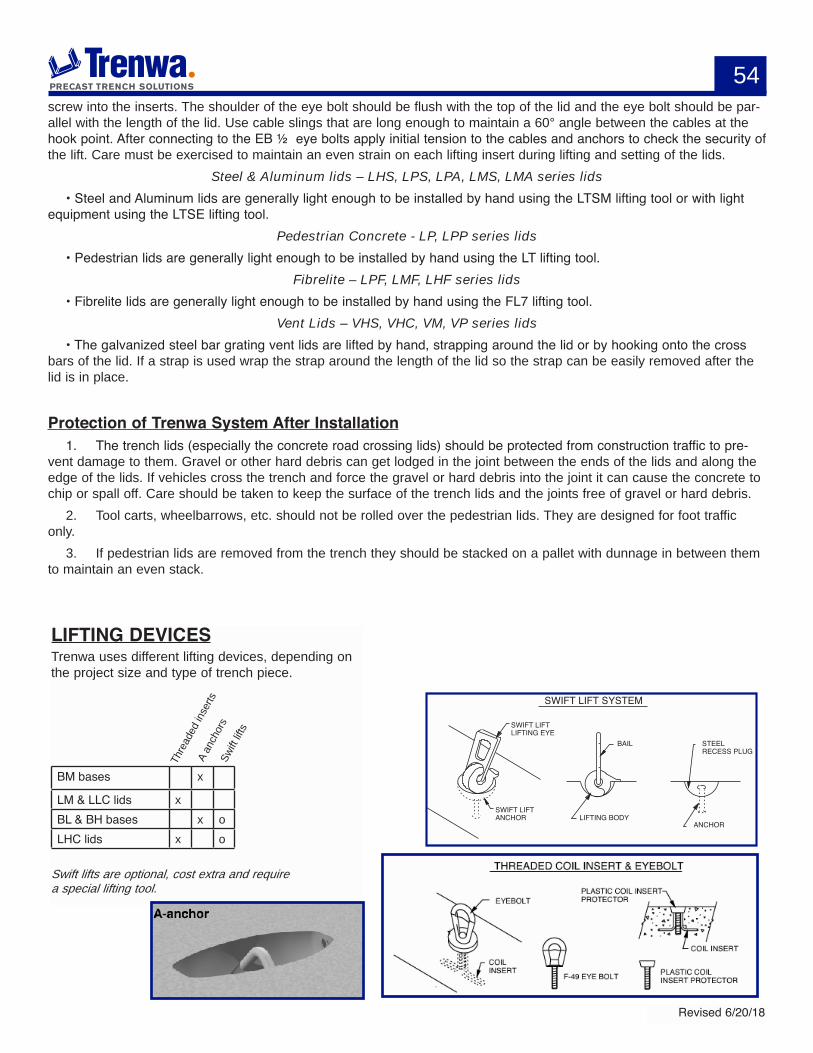
LIFTING DEVICESTrenwa uses different lifting devices, depending on the project size and type of trench piece.
BM bases x
LM & LLC lids xBL & BH bases x oLHC lids x o
Swift lifts are optional, cost extra and requirea special lifting tool.
Thre
aded
inse
rtsA
anch
ors
Swift
lifts
SWIFT LIFT SYSTEM
SWIFT LIFT ANCHOR
SWIFT LIFT LIFTING EYE
BAIL
LIFTING BODY
STEEL RECESS PLUG
ANCHOR
screw into the inserts. The shoulder of the eye bolt should be flush with the top of the lid and the eye bolt should be par-allel with the length of the lid. Use cable slings that are long enough to maintain a 60° angle between the cables at the hook point. After connecting to the EB ½ eye bolts apply initial tension to the cables and anchors to check the security of the lift. Care must be exercised to maintain an even strain on each lifting insert during lifting and setting of the lids.
Steel & Aluminum lids – LHS, LPS, LPA, LMS, LMA series lids• Steel and Aluminum lids are generally light enough to be installed by hand using the LTSM lifting tool or with light
equipment using the LTSE lifting tool.Pedestrian Concrete - LP, LPP series lids
• Pedestrian lids are generally light enough to be installed by hand using the LT lifting tool.Fibrelite – LPF, LMF, LHF series lids
• Fibrelite lids are generally light enough to be installed by hand using the FL7 lifting tool.Vent Lids – VHS, VHC, VM, VP series lids
• The galvanized steel bar grating vent lids are lifted by hand, strapping around the lid or by hooking onto the cross bars of the lid. If a strap is used wrap the strap around the length of the lid so the strap can be easily removed after the lid is in place.
Protection of Trenwa System After Installation1. The trench lids (especially the concrete road crossing lids) should be protected from construction traffic to pre-
vent damage to them. Gravel or other hard debris can get lodged in the joint between the ends of the lids and along the edge of the lids. If vehicles cross the trench and force the gravel or hard debris into the joint it can cause the concrete to chip or spall off. Care should be taken to keep the surface of the trench lids and the joints free of gravel or hard debris.
2. Tool carts, wheelbarrows, etc. should not be rolled over the pedestrian lids. They are designed for foot traffic only.
3. If pedestrian lids are removed from the trench they should be stacked on a pallet with dunnage in between them to maintain an even stack.
55
Revised 6/20/18
55Component Trench
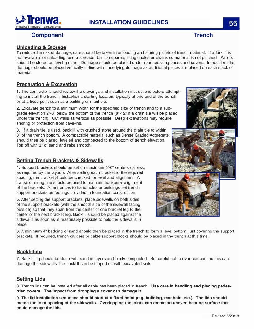
Unloading & StorageTo reduce the risk of damage, care should be taken in unloading and storing pallets of trench material. If a forklift is not available for unloading, use a spreader bar to separate lifting cables or chains so material is not pinched. Pallets should be stored on level ground. Dunnage should be placed under road crossing bases and covers. In addition, the dunnage should be placed vertically in-line with underlying dunnage as additional pieces are placed on each stack of material.
Preparation & Excavation1. The contractor should review the drawings and installation instructions before attempt-ing to install the trench. Establish a starting location, typically at one end of the trench or at a fixed point such as a building or manhole.2. Excavate trench to a minimum width for the specified size of trench and to a sub-grade elevation 2"-3" below the bottom of the trench (8"-12" if a drain tile will be placed under the trench). Cut walls as vertical as possible. Deep excavations may require shoring or protection from cave-ins.3. If a drain tile is used, backfill with crushed stone around the drain tile to within 3" of the trench bottom. A compactible material such as Dense Graded Aggregate should then be placed, leveled and compacted to the bottom of trench elevation. Top off with 1" of sand and rake smooth.
Setting Trench Brackets & Sidewalls4. Support brackets should be set on maximum 5’-0" centers (or less, as required by the layout). After setting each bracket to the required spacing, the bracket should be checked for level and alignment. A transit or string line should be used to maintain horizontal alignment of the brackets. At entrances to hand holes or buildings set trench support brackets on footings provided in foundation construction. 5. After setting the support brackets, place sidewalls on both sides of the support brackets (with the smooth side of the sidewall facing outside) so that they span from the center of one bracket leg to the center of the next bracket leg. Backfill should be placed against the sidewalls as soon as is reasonably possible to hold the sidewalls in place.6. A minimum 4" bedding of sand should then be placed in the trench to form a level bottom, just covering the support brackets. If required, trench dividers or cable support blocks should be placed in the trench at this time.
Backfilling7. Backfilling should be done with sand in layers and firmly compacted. Be careful not to over-compact as this can damage the sidewalls The backfill can be topped off with excavated soils.
Setting Lids8. Trench lids can be installed after all cable has been placed in trench. Use care in handling and placing pedes-trian covers. The impact from dropping a cover can damage it.9. The lid installation sequence should start at a fixed point (e.g. building, manhole, etc.). The lids should match the joint spacing of the sidewalls. Overlapping the joints can create an uneven bearing surface that could damage the lids.
INSTALLATION GUIDELINES
56
Revised 6/20/18
56TRENCH SPECIFICATIONS
GENERAL SPECIFICATIONS
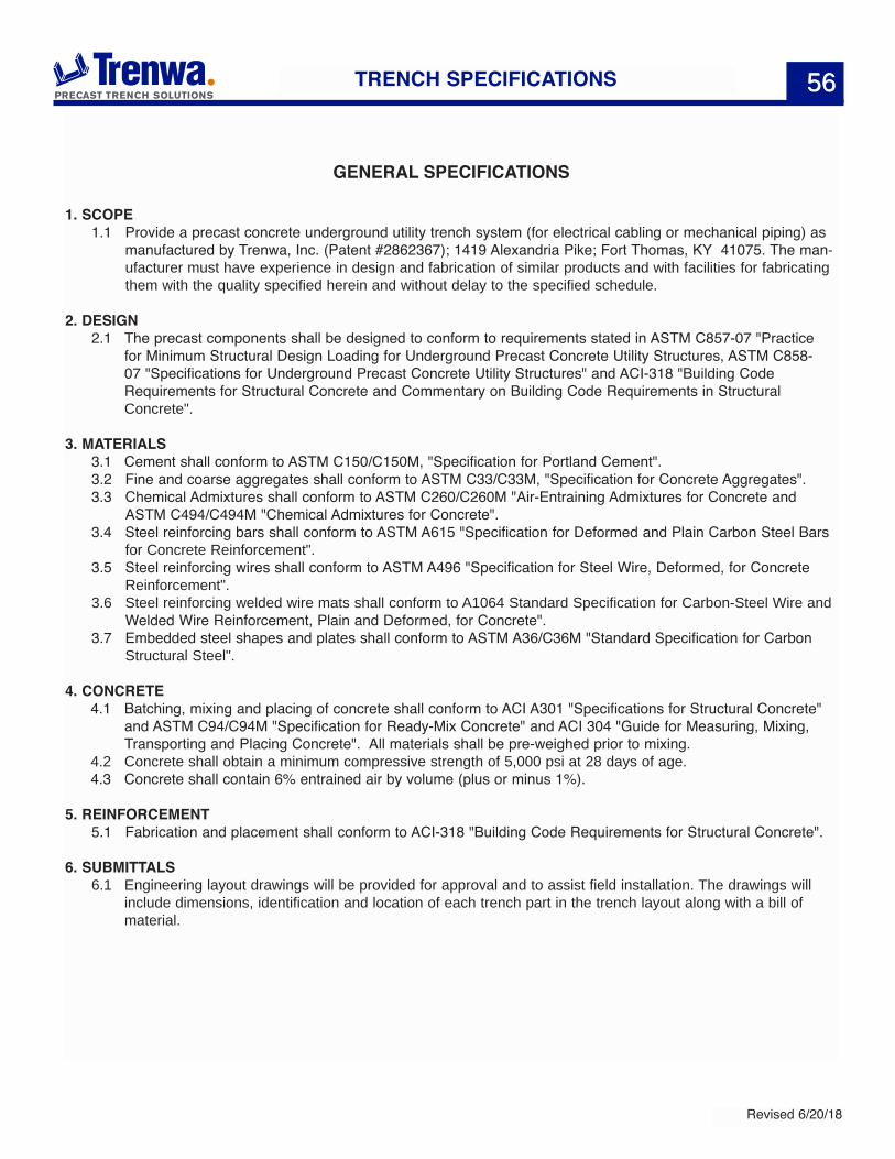
1. SCOPE1.1 Provide a precast concrete underground utility trench system (for electrical cabling or mechanical piping) as
manufactured by Trenwa, Inc. (Patent #2862367); 1419 Alexandria Pike; Fort Thomas, KY 41075. The man-ufacturer must have experience in design and fabrication of similar products and with facilities for fabricating them with the quality specified herein and without delay to the specified schedule.
2. DESIGN 2.1 The precast components shall be designed to conform to requirements stated in ASTM C857-07 "Practice
for Minimum Structural Design Loading for Underground Precast Concrete Utility Structures, ASTM C858-07 "Specifications for Underground Precast Concrete Utility Structures" and ACI-318 "Building Code Requirements for Structural Concrete and Commentary on Building Code Requirements in Structural Concrete".
3. MATERIALS 3.1 Cement shall conform to ASTM C150/C150M, "Specification for Portland Cement".
3.2 Fine and coarse aggregates shall conform to ASTM C33/C33M, "Specification for Concrete Aggregates".3.3 Chemical Admixtures shall conform to ASTM C260/C260M "Air-Entraining Admixtures for Concrete and
ASTM C494/C494M "Chemical Admixtures for Concrete".3.4 Steel reinforcing bars shall conform to ASTM A615 "Specification for Deformed and Plain Carbon Steel Bars
for Concrete Reinforcement".3.5 Steel reinforcing wires shall conform to ASTM A496 "Specification for Steel Wire, Deformed, for Concrete
Reinforcement".3.6 Steel reinforcing welded wire mats shall conform to A1064 Standard Specification for Carbon-Steel Wire and
Welded Wire Reinforcement, Plain and Deformed, for Concrete".3.7 Embedded steel shapes and plates shall conform to ASTM A36/C36M "Standard Specification for Carbon
Structural Steel".
4. CONCRETE4.1 Batching, mixing and placing of concrete shall conform to ACI A301 "Specifications for Structural Concrete"
and ASTM C94/C94M "Specification for Ready-Mix Concrete" and ACI 304 "Guide for Measuring, Mixing, Transporting and Placing Concrete". All materials shall be pre-weighed prior to mixing.
4.2 Concrete shall obtain a minimum compressive strength of 5,000 psi at 28 days of age.4.3 Concrete shall contain 6% entrained air by volume (plus or minus 1%).
5. REINFORCEMENT5.1 Fabrication and placement shall conform to ACI-318 "Building Code Requirements for Structural Concrete".
6. SUBMITTALS 6.1 Engineering layout drawings will be provided for approval and to assist field installation. The drawings will
include dimensions, identification and location of each trench part in the trench layout along with a bill of material.
57
Revised 6/20/18
TRENCH SPECIFICATIONS
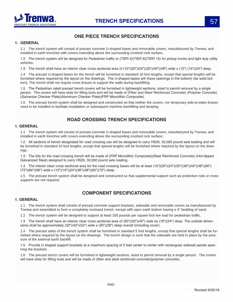
ONE PIECE TRENCH SPECIFICATIONS1. GENERAL
1.1 The trench system will consist of precast concrete U-shaped bases and removable covers, manufactured by Trenwa, and installed in earth trenches with covers extending above the surrounding crushed rock surface.1.2 The trench system will be designed for Pedestrian traffic or (TIER 5)(TIER 8)(TIER 15) for pickup trucks and light duty utility vehicles.1.3 The trench shall have an interior clear cross sectional area of (10")(20")(24")(30")(40")(48") wide x (12") (15")(24") deep. 1.4 The precast U-shaped bases for the trench will be furnished in standard 10 foot lengths, except that special lengths will be furnished where required by the layout on the drawings. The U-shaped bases will (have openings in the bottom) (be solid bot-tom). The trench shall not require cross braces to support the walls during backfilling.1.5 The Pedestrian rated precast trench covers will be furnished in lightweight sections, sized to permit removal by a single person. The covers will have slots for lifting tools and will be made of (Fiber and Steel Reinforced Concrete) (Polymer Concrete)(Galvanize Checker Plate)(Aluminum Checker Plate)(FRP Monolithic Composite).1.6 The precast trench system shall be designed and constructed so that neither the covers, nor temporary side-to-sides braces need to be installed to facilitate installation or subsequent machine backfilling and tamping.
ROAD CROSSING TRENCH SPECIFICATIONS1. GENERAL
1.1 The trench system will consist of precast concrete U-shaped bases and removable covers, manufactured by Trenwa, and installed in earth trenches with covers extending above the surrounding crushed rock surface. 1.2 All sections of trench designated for road crossing use will be designed to carry HS20, 32,000 pound axle loading and will be furnished in standard 10 foot lengths, except that special lengths will be furnished where required by the layout on the draw-ings.1.3 The lids for the road crossing trench will be made of (FRP Monolithic Composite)(Steel Reinforced Concrete) (Hot-dipped Galvanized Steel) designed to carry HS20, 32,000 pound axle loading.1.4 The interior clear cross sectional area for the road crossing bases will be at least (10")(20")(24")(30")(36")(40")(48")(60")(72")(84")(96") wide x (12")(16")(24")(36")(48")(60")(72") deep.1.5 The precast trench system shall be designed and constructed so that supplemental support such as protection rods or cross supports are not required.
COMPONENT SPECIFICATIONS1. GENERAL
1.1 The trench system shall consist of precast concrete support brackets, sidewalls and removable covers as manufactured by Trenwa and assembled to form a completely enclosed trench, except with open earth bottom having a 4" bedding of sand.1.2 The trench system will be designed to support at least 200 pounds per square foot live load for pedestrian traffic.1.3 The trench shall have an interior clear cross sectional area of (20")(30")(40") wide by (16")(24") deep. The outside dimen-sions shall be approximately (32")(42")(52") wide x (20")(28") deep overall (including cover).1.4 The precast sides of the trench system shall be furnished in standard 5 foot lengths, except that special lengths shall be fur-nished where required by the layout on the drawings. The trench design is such that the sidewalls are held in place by the pres-sure of the external earth backfill.1.5 Provide U shaped support brackets at a maximum spacing of 5 feet center to center with rectangular sidewall panels span-ning the brackets .1.6 The precast trench covers will be furnished in lightweight sections, sized to permit removal by a single person. The covers will have slots for lifting tools and will be made of (fiber and steel reinforced concrete)(polymer concrete).
-END-


