Towards a deployable satellite gripper based on multisegment dielectric elastomer minimum energy structures O. A. Araromi, I. Gavrilovich, J. Shintake, S. Rosset, H. R. Shea Proc. SPIE 9056, Electroactive Polymer Actuators and Devices (EAPAD) 2014, 90562G (March 13, 2014); doi: 10.1117/12.2044667 Copyright 2013 Society of Photo4Optical Instrumentation Engineers. One print or electronic copy may be made for personal use only. Systematic electronic or print reproduction and distribution, duplication of any material in this paper for a fee or for commercial purposes, or modification of the content of the paper are prohibited. http://dx.doi.org/10.1117/12.2044667
Transcript
Towards a deployable satellite gripper based on multisegment dielectric elastomer minimum energy
structures
O. A. Araromi, I. Gavrilovich, J. Shintake, S. Rosset, H. R. Shea Proc. SPIE 9056, Electroactive Polymer Actuators and Devices (EAPAD) 2014, 90562G (March 13, 2014); doi: 10.1117/12.2044667 Copyright*2013*Society*of*Photo4Optical*Instrumentation*Engineers.*One*print*or*electronic*copy*may*be*made*for*personal*use*only.*Systematic*electronic*or*print*reproduction*and*distribution,*duplication*of*any*material*in*this*paper*for*a*fee*or*for*commercial*purposes,*or*modification*of*the*content*of*the*paper*are*prohibited.**http://dx.doi.org/10.1117/12.2044667*
Towards a deployable satellite gripper based on multisegment dielectric elastomer minimum energy structures
O. A. Araromi*a, I. Gavrilovichb, J. Shintakea, S. Rosseta, H. R. Sheaa
aMicrosystems For Space Technologies Laboratory, École Polytechnique Fédérale de Lausanne, Neuchâtel, Switzerland;
bSwiss Space Center, École Polytechnique Fédérale de Lausanne (EPFL), Lausanne, Switzerland
ABSTRACT
Dielectric Elastomer Actuators (DEAs) are an emerging actuation technology which are inherent lightweight and compliant in nature, enabling the development of unique and versatile devices, such as the Dielectric Elastomer Minimum Energy Structure (DEMES). We present the development of a multisegment DEMES actuator for use in a deployable microsatellite gripper. The satellite, called CleanSpace One, will demonstrate active debris removal (ADR) in space using a small cost effective system. The inherent flexibility and lightweight nature of the DEMES actuator enables space efficient storage (e.g. in a rolled configuration) of the gripper prior to deployment. Multisegment DEMES have multiple open sections and are an effective way of amplifying bending deformation. We present the evolution of our DEMES actuator design from initial concepts up until the final design, describing briefly the trade-offs associated with each method. We describe the optimization of our chosen design concept and characterize this design in terms on bending angle as a function of input voltage and gripping force. Prior to the characterization the actuator was stored and subsequently deployed from a rolled state, a capability made possible thanks to the fabrication methodology and materials used. A tip angle change of approximately 60º and a gripping force of 0.8 mN (for small deflections from the actuator tip) were achieved. The prototype actuators (approximately 10 cm in length) weigh a maximum of 0.65 g and are robust and mechanically resilient, demonstrating over 80,000 activation cycles.
Keywords: Dielectric elastomer minimum energy structures (DEMES), dielectric elastomer actuators (DEA), active debris removal (ADR), deployable systems.
1. INTRODUCTION Every year hundreds of spacecraft are launched. Many launches lead to debris accumulation in low Earth orbits (e.g. spent rocket bodies, the spacecraft themselves at end of life). This debris presents a significant problem for operational space technologies in earth orbit, as shown by the collision of the operational Iridium 33 satellite and the inactive Kosmos 2251 satellite in 20091. As a step in the mitigation of this issue, the Clean-mE project has been proposed by the Swiss Space Center. The project aims to use a cost effective microsatellite (~30-40 kg) called CleanSpace One (CSO) to perform active debris removal (ADR) in space2. The capture target for CSO’s first missions is the 100 mm ×100 mm ×100 mm CubeSat named SwissCube weighing 820g, launched in September 20093. SwissCube is smaller than some space debris (which can weigh as much as 9000 kg), however the capture of SwissCube presents an important first step in the development of ADR technologies for more common scale space debris. An important aspect of this project is the end-effector which will be used to capture SwissCube. Due to the small size of the CSO satellite, a lightweight end-effector which occupies a small volume is required.
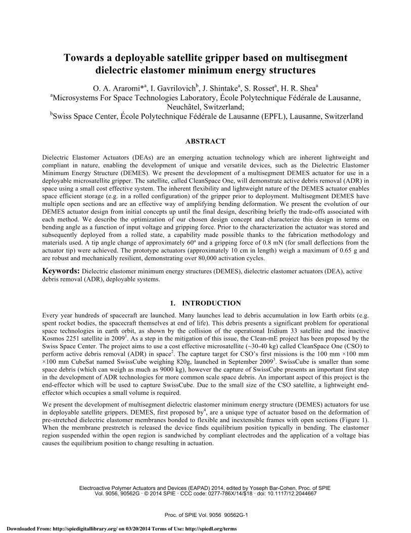
We present the development of multisegment dielectric elastomer minimum energy structure (DEMES) actuators for use in deployable satellite grippers. DEMES, first proposed by4, are a unique type of actuator based on the deformation of pre-stretched dielectric elastomer membranes bonded to flexible and inextensible frames with open sections (Figure 1). When the membrane prestretch is released the device finds equilibrium position typically in bending. The elastomer region suspended within the open region is sandwiched by compliant electrodes and the application of a voltage bias causes the equilibrium position to change resulting in actuation.
Downloaded From: http://spiedigitallibrary.org/ on 03/20/2014 Terms of Use: http://spiedl.org/terms
DEMES have shown promise for gripping applications5 and their inherent flexibility and lightweight nature are uniquely advantageous for this mission, especially when compared to other potential solutions such as robotic arms, harpoons or nets6. The use of multi-segment devices adds stability to the actuator, limiting the number of equilibrium positions it can take (Figure 1(b)). Moreover, theoretical analysis suggests that the change in bending angle in response to an applied voltage decreases the larger the initial actuator curvature (large initial bending angle)7, so for long actuators it is more optimal to have several small curvature segments than a single large curvature device.
In this work we outline the different stages of development for our actuator design, describing briefly the trade-offs associated with each design concept. We present our final actuator design and outline its fabrication process, which benefits from the use of silicone elastomers and pad printed electrodes, producing robust actuators resilient to mechanical deformations. We lastly show the result of a characterization of one of our devices in terms of tip angle as a function of the applied voltage and gripping (reaction) force as a function of linear displacement of the actuator tip. We also demonstrate successful low volume storage with our device by rolling it into a cylinder and deploying prior to characterization. A cyclic test is also performed to demonstrate the repeatability of its operation.
2. DEVICE DESIGN
Figure 2 shows a conceptual drawing of CSO and its gripper along with the main stages of the proposed capture procedure using the multisegment DEMES actuators. In the first stage the gripper is stored in rolled form during launch and cruise. In the second stage, the gripper is deployed and the allowed to reach its equilibrium position as a result of stored elastic forces, followed by the application of a voltage which opens the gripper. In the third stage CSO rendezvous with CubeSat, the voltage is deactivated and the actuators close in on SwissCube. The frictional forces between the gripper and SwissCube cause SwissCube to detumble (i.e. slow is rotational velocity). In the fourth stage the gripper has secured SwissCube such that there is zero relative rotation between SwissCube and CSO.
Initial calculations based on a simplified model specified the required grasping force i.e. the normal force imposed by a single actuator on the surface of SwissCube, to be between 0.001 mN and 6.5 mN for short detumbling durations, assuming CubeSat initial rotational velocities between 1 and 50 degrees/s8. In principle only a small change in tip angle is required from the DEMES actuator as the gripper only needs to open sufficiently to accommodate the debris being captured. However, in general it is desired that the maximum bending be as large as possible to relax the accuracy requirements for the rendezvous systems onboard CSO.
(a) (b)
Figure 1. Example minimum energy structure. (a) On the left, a prestretched PDMS membrane is bonded to a flexible and inextensible frame (shown with hatching superimposed for clarity). On the right, the membrane prestretch is released and the structure finds an equilibrium position. (b) A second possible equilibrium position with this MES example. The areas shaded in green are where the electrode would be in a dielectric elastomer minimum energy structure.
Proc. of SPIE Vol. 9056 90562G-2
Downloaded From: http://spiedigitallibrary.org/ on 03/20/2014 Terms of Use: http://spiedl.org/terms
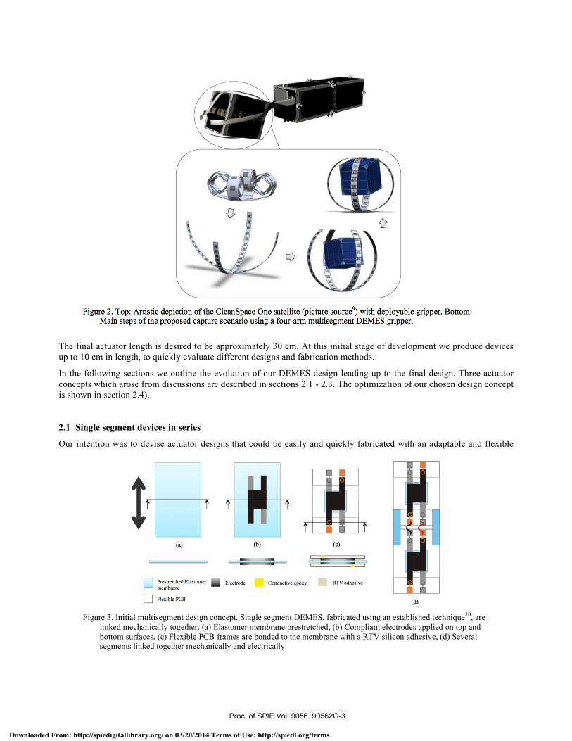
Figure 2. Top: Artistic depiction of the CleanSpace One satellite (picture source) with deployable gripper. Bottom:Main steps of the proposed capture scenario using a four -arm multisegment DEMES gripper.
T
nu
Iulpi
(a)
N(b) (e)
JPmtretched Elastomer III Electrode Conductive epoxy RTV adhesivemembrane
Flexible PCB (d)
The final actuator length is desired to be approximately 30 cm. At this initial stage of development we produce devices up to 10 cm in length, to quickly evaluate different designs and fabrication methods.
In the following sections we outline the evolution of our DEMES design leading up to the final design. Three actuator concepts which arose from discussions are described in sections 2.1 - 2.3. The optimization of our chosen design concept is shown in section 2.4).
2.1 Single segment devices in series
Our intention was to devise actuator designs that could be easily and quickly fabricated with an adaptable and flexible
Figure 2. Top: Artistic depiction of the CleanSpace One satellite (picture source9) with deployable gripper. Bottom:
Main steps of the proposed capture scenario using a four-arm multisegment DEMES gripper.
Figure 3. Initial multisegment design concept. Single segment DEMES, fabricated using an established technique10, are
linked mechanically together. (a) Elastomer membrane prestretched, (b) Compliant electrodes applied on top and bottom surfaces, (c) Flexible PCB frames are bonded to the membrane with a RTV silicon adhesive, (d) Several segments linked together mechanically and electrically.
Proc. of SPIE Vol. 9056 90562G-3
Downloaded From: http://spiedigitallibrary.org/ on 03/20/2014 Terms of Use: http://spiedl.org/terms
Frame
Electrodes' °FrÎ rMembranes
Frame
I
process - capable of being used for a variety of devices sizes and shapes. Figure 3 illustrates our first actuator design concept; the design consists of several single segment devices linked mechanically together. Each segment consist of a prestretched PDMS membrane stretched in pure shear along the device length (Figure 3(a)), pad printed electrodes applied to its top and bottom surfaces (Figure 3(b)), and bonded to a flexible PCB with copper tracks using an RTV silicone adhesive10 (Figure 3(c)). The RTV adhesive is applied in a thin film to prevent over stiffening the actuator frame. This concept had the advantage of being modular (and therefore scalable to large geometries) using a fabrication process and actuator design very similar to one already in use in our laboratory10. Despite the advantages of this concept, it was feared that the linking method would produce an actuator with low mechanical robustness and fragile electrical connections. Enhancing mechanical resilience, through the use of stiffer materials or stiff adhesives for example, was undesirable as they would inhibit low volume storage.
2.2 Multiple patterned membranes sandwiched between two frames
A variation of the first DEMES design concept is shown in Figure 4. In this scenario, several prestretched elastomer membranes, patterned with an electrode, are sandwiched between two flexible PCB frames. One of the PCB frames is half the thickness of the other allowing the actuator to find equilibrium in bending once the membrane prestretches are released. The method of using two frames which are continuous along the actuator length removed the need for mechanical linkages. However, initial trials at attempting to bond individual membranes to a frame proved difficult and ultimately impractical (Figure 4). The membranes were glued to one of the frames and then released by laser cutting (with a laser power sufficient only to cut the membrane and not the frame). Once released the membranes would curl-up making bonding of the next membrane cumbersome. Moreover, this curling would at times cause the membrane to detached from the frame due to the thin adhesive layer used (Figure 4).
2.3 Single-membrane: Sandwiched between two frames
A “single-membrane” approach, depicted in Figure 5, was subsequently favored over the previous approaches due to the ability to bond the elastomer membrane to the frame in one process. This approach uses a single PDMS membrane with several electrode segments patterned onto it, sandwiched between two flexible PCB frames. As with the previous design concept one of the frames is half the thickness of the other. This approach proved simpler and more reliable to fabricate but is not as flexible as the other designs from a fabrication point of view, potentially requiring large areas of elastomer membranes when larger devices are required. A trial fabrication attempt using this approach produced actuators with a very small initial curvatures (Figure 5 (b)) and change in bending angle produced when activated, most likely resulting
Figure 4. Second DEMES design concept utilizing two flexible PCB frames sandwiching several individually bonded,
prestretch elastomer membranes with compliant electrode. Bottom: Unsuccessful attempts at bonding individual elastomer membranes to a PCB frame, curling up of frame after bonding made the bonding of subsequent membranes difficult and the adhering of the second PCB frame impractical (red circle area of detachment due to bending of frame in fabrication).
Proc. of SPIE Vol. 9056 90562G-4
Downloaded From: http://spiedigitallibrary.org/ on 03/20/2014 Terms of Use: http://spiedl.org/terms
2.
3.WMU Prestretched Elastomer
membrane
Conductive epoxy- ----n- -I E Plastic membraneholder
Electrode
RTV adhesive
Prestretched Elastomermembrane
Plastic membrane holder
1.
2.
3.
Kepton Tape
. Electrode
---
Gap between electrodeand frame Round corners
PI film + double -sidedKapton tape
4. Printed electrodesinstead of copper tracksNO cured adhesive!
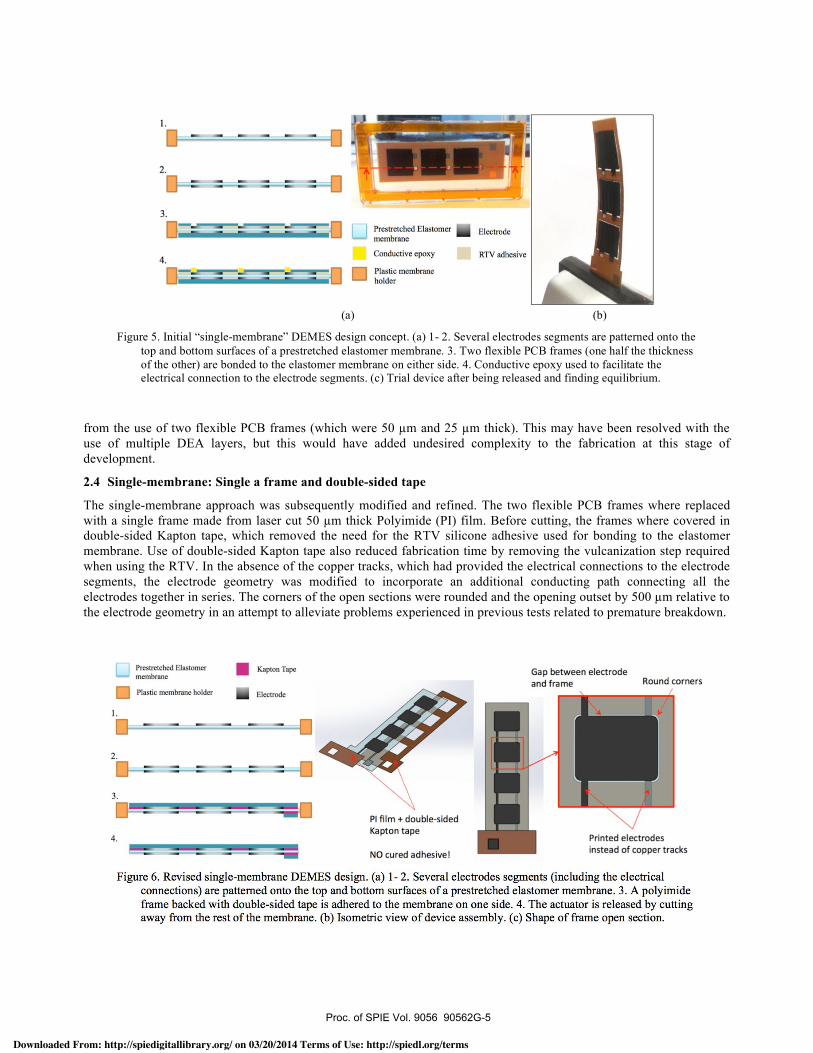
Figure 6. Revised single - membrane DEMES design. (a) 1- 2. Several electrodes segments (including the electricalconnections) are patterned onto the top and bottom surfaces of a prestretched elastomer membrane. 3. A polyimideframe backed with double -sided tape is adhered to the membrane on one side. 4. The actuator is released by cuttingaway from the rest of the membrane. (b) Isometric view of device assembly. (c) Shape of frame open section.
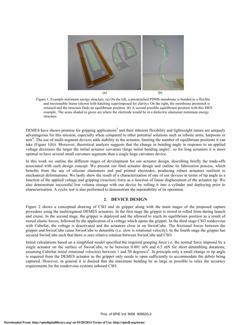
from the use of two flexible PCB frames (which were 50 µm and 25 µm thick). This may have been resolved with the use of multiple DEA layers, but this would have added undesired complexity to the fabrication at this stage of development.
2.4 Single-membrane: Single a frame and double-sided tape
The single-membrane approach was subsequently modified and refined. The two flexible PCB frames where replaced with a single frame made from laser cut 50 µm thick Polyimide (PI) film. Before cutting, the frames where covered in double-sided Kapton tape, which removed the need for the RTV silicone adhesive used for bonding to the elastomer membrane. Use of double-sided Kapton tape also reduced fabrication time by removing the vulcanization step required when using the RTV. In the absence of the copper tracks, which had provided the electrical connections to the electrode segments, the electrode geometry was modified to incorporate an additional conducting path connecting all the electrodes together in series. The corners of the open sections were rounded and the opening outset by 500 µm relative to the electrode geometry in an attempt to alleviate problems experienced in previous tests related to premature breakdown.
Figure 6. Revised single-membrane DEMES design. (a) 1- 2. Several electrodes segments (including the electrical
connections) are patterned onto the top and bottom surfaces of a prestretched elastomer membrane. 3. A polyimide frame backed with double-sided tape is adhered to the membrane on one side. 4. The actuator is released by cutting away from the rest of the membrane. (b) Isometric view of device assembly. (c) Shape of frame open section.
(a) (b)
Figure 5. Initial “single-membrane” DEMES design concept. (a) 1- 2. Several electrodes segments are patterned onto the top and bottom surfaces of a prestretched elastomer membrane. 3. Two flexible PCB frames (one half the thickness of the other) are bonded to the elastomer membrane on either side. 4. Conductive epoxy used to facilitate the electrical connection to the electrode segments. (c) Trial device after being released and finding equilibrium.
Proc. of SPIE Vol. 9056 90562G-5
Downloaded From: http://spiedigitallibrary.org/ on 03/20/2014 Terms of Use: http://spiedl.org/terms
(a) (b) (e)
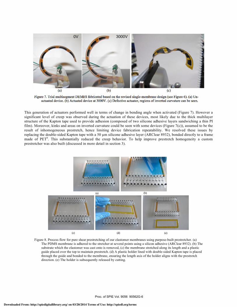
Figure 7. Trial multisegment DEMES fabricated based on the revised single -membrane design (see Figure 6). (a) Un-actuated device. (b) Actuated device at 3000V. (c) Defective actuator, regions of inverted curvature can be seen.
(3) IPi
(y)
1 7l
, n 1 a n n n r r rf 1 4
al1
This generation of actuators performed well in terms of change in bending angle when activated (Figure 7). However a significant level of creep was observed during the actuation of these devices, most likely due to the thick multilayer structure of the Kapton tape used to provide adhesion (composed of two silicone adhesive layers sandwiching a thin PI film). Moreover, kinks and areas on inverted curvature could be seen with some devices (Figure 7(c)), assumed to be the result of inhomogeneous prestretch, hence limiting device fabrication repeatability. We resolved these issues by replacing the double-sided Kapton tape with a 50 µm silicone adhesive layer (ARClear 8932), bonded directly to a frame made of PET6. This substantially reduced the creep behavior. To help improve prestretch homogeneity a custom prestretcher was also built (discussed in more detail in section 3).
(a) (b) (c)
Figure 7. Trial multisegment DEMES fabricated based on the revised single-membrane design (see Figure 6). (a) Un-
actuated device. (b) Actuated device at 3000V. (c) Defective actuator, regions of inverted curvature can be seen.
Figure 8. Process flow for pure shear prestretching of our elastomer membranes using purpose-built prestretcher. (a)
The PDMS membrane is adhered to the stretcher at several points using a silicon adhesive (ARClear 8932). (b) The
substrate which the elastomer was cast onto is removed, (c) the membrane stretched along its length and a plastic
guide placed over the top to maintain prestretch. (d) A plastic holder lined with double-sided Kapton tape is placed
through the guide and bonded to the membrane, ensuring the length axis of the holder aligns with the prestretch
direction. (e) The holder is subsequently released by cutting.
Proc. of SPIE Vol. 9056 90562G-6
Downloaded From: http://spiedigitallibrary.org/ on 03/20/2014 Terms of Use: http://spiedl.org/terms
3. ACTUATOR FABRICATION AND CHARACTERIZTION We experimentally characterized our final DEMES design in terms of tip deflection and gripping force. We use a two part PDMS (Sylgard 186, Dow Corning) as the elastomer membrane. The two components of the PDMS are mixed together using a planetary mixer (Thinky ARE-310) at 10:1 wt% (base:curing agent) with the addition of a solvent (Dow corning, OS-20) at 20 wt% solvent fraction relative to the PDMS mixture. The PDMS was blade cast onto a PET substrate to a thickness of approximately 70 µm using a Zehntner automatic film applicator coater and subsequently cross-linked at 80º in an oven for approximately one hour. Once cured the membranes were cut into 80 mm by 45 mm sections and fixed to custom built prestretcher device, shown in Figure 8, and stretched 1.3 times in length in pure shear (i.e. width kept constant). A pure shear prestretch was used to help avoid loss of tension in the membrane width direction during actuation. Once prestretched the membrane is fixed to a plastic holder with double-sided tape.
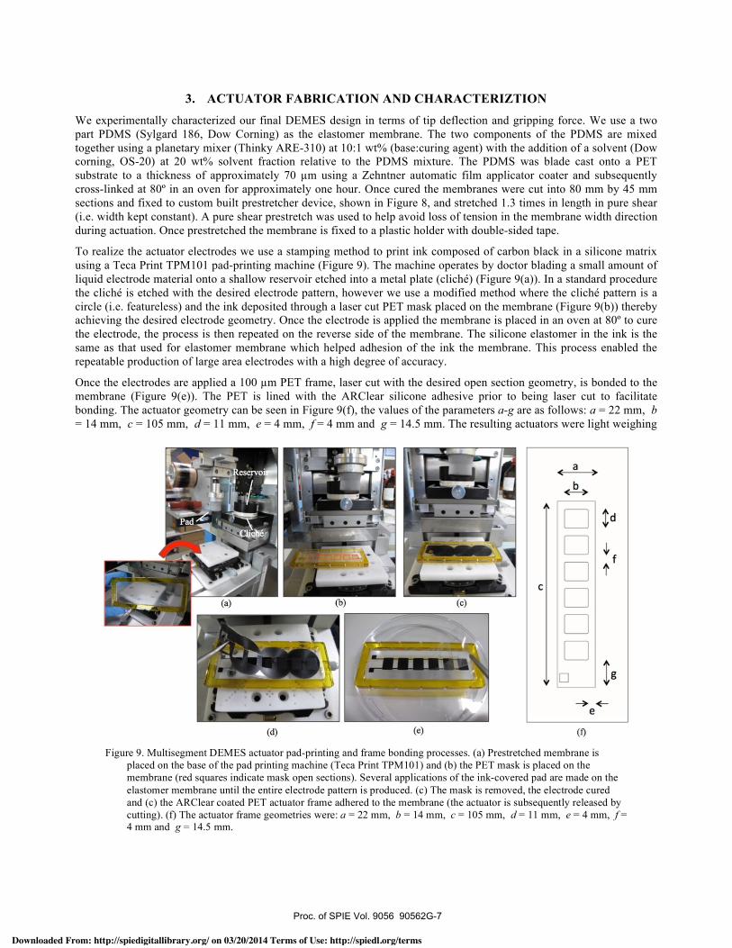
To realize the actuator electrodes we use a stamping method to print ink composed of carbon black in a silicone matrix using a Teca Print TPM101 pad-printing machine (Figure 9). The machine operates by doctor blading a small amount of liquid electrode material onto a shallow reservoir etched into a metal plate (cliché) (Figure 9(a)). In a standard procedure the cliché is etched with the desired electrode pattern, however we use a modified method where the cliché pattern is a circle (i.e. featureless) and the ink deposited through a laser cut PET mask placed on the membrane (Figure 9(b)) thereby achieving the desired electrode geometry. Once the electrode is applied the membrane is placed in an oven at 80º to cure the electrode, the process is then repeated on the reverse side of the membrane. The silicone elastomer in the ink is the same as that used for elastomer membrane which helped adhesion of the ink the membrane. This process enabled the repeatable production of large area electrodes with a high degree of accuracy.
Once the electrodes are applied a 100 µm PET frame, laser cut with the desired open section geometry, is bonded to the membrane (Figure 9(e)). The PET is lined with the ARClear silicone adhesive prior to being laser cut to facilitate bonding. The actuator geometry can be seen in Figure 9(f), the values of the parameters a-g are as follows: a = 22 mm, b = 14 mm, c = 105 mm, d = 11 mm, e = 4 mm, f = 4 mm and g = 14.5 mm. The resulting actuators were light weighing
Figure 9. Multisegment DEMES actuator pad-printing and frame bonding processes. (a) Prestretched membrane is
placed on the base of the pad printing machine (Teca Print TPM101) and (b) the PET mask is placed on the membrane (red squares indicate mask open sections). Several applications of the ink-covered pad are made on the elastomer membrane until the entire electrode pattern is produced. (c) The mask is removed, the electrode cured and (c) the ARClear coated PET actuator frame adhered to the membrane (the actuator is subsequently released by cutting). (f) The actuator frame geometries were: a = 22 mm, b = 14 mm, c = 105 mm, d = 11 mm, e = 4 mm, f = 4 mm and g = 14.5 mm.
Proc. of SPIE Vol. 9056 90562G-7
Downloaded From: http://spiedigitallibrary.org/ on 03/20/2014 Terms of Use: http://spiedl.org/terms
(a)
(b)
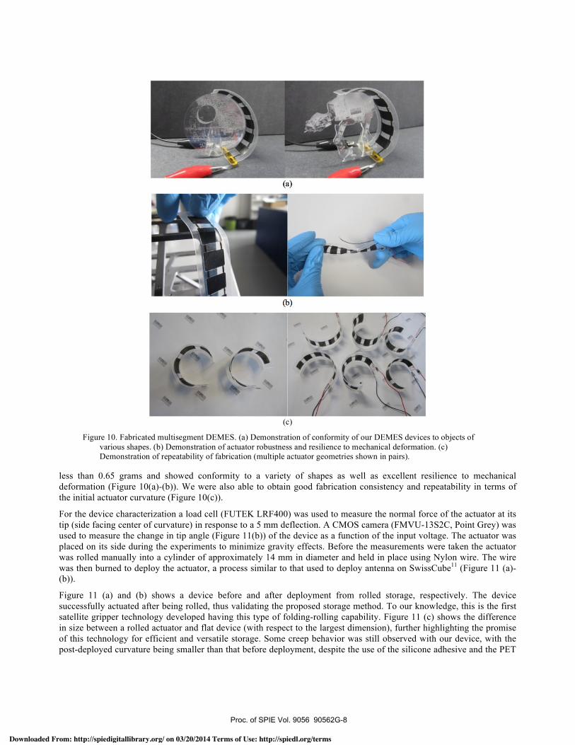
less than 0.65 grams and showed conformity to a variety of shapes as well as excellent resilience to mechanical deformation (Figure 10(a)-(b)). We were also able to obtain good fabrication consistency and repeatability in terms of the initial actuator curvature (Figure 10(c)).
For the device characterization a load cell (FUTEK LRF400) was used to measure the normal force of the actuator at its tip (side facing center of curvature) in response to a 5 mm deflection. A CMOS camera (FMVU-13S2C, Point Grey) was used to measure the change in tip angle (Figure 11(b)) of the device as a function of the input voltage. The actuator was placed on its side during the experiments to minimize gravity effects. Before the measurements were taken the actuator was rolled manually into a cylinder of approximately 14 mm in diameter and held in place using Nylon wire. The wire was then burned to deploy the actuator, a process similar to that used to deploy antenna on SwissCube11 (Figure 11 (a)-(b)).
Figure 11 (a) and (b) shows a device before and after deployment from rolled storage, respectively. The device successfully actuated after being rolled, thus validating the proposed storage method. To our knowledge, this is the first satellite gripper technology developed having this type of folding-rolling capability. Figure 11 (c) shows the difference in size between a rolled actuator and flat device (with respect to the largest dimension), further highlighting the promise of this technology for efficient and versatile storage. Some creep behavior was still observed with our device, with the post-deployed curvature being smaller than that before deployment, despite the use of the silicone adhesive and the PET
(a)
(b)
(c)
Figure 10. Fabricated multisegment DEMES. (a) Demonstration of conformity of our DEMES devices to objects of various shapes. (b) Demonstration of actuator robustness and resilience to mechanical deformation. (c) Demonstration of repeatability of fabrication (multiple actuator geometries shown in pairs).
Proc. of SPIE Vol. 9056 90562G-8
Downloaded From: http://spiedigitallibrary.org/ on 03/20/2014 Terms of Use: http://spiedl.org/terms
0
-20
(a) (b)0.8
0.7
0.6
(c)
-1200 500 1000 1500 2000 2500 3000 3500 4000
Voltage (V)
CIGa020.1
oo 1 2 3 4 5
Linear displacement (mm)6
frame. In future designs this could be alleviated by using low creep plastics such as polyethersulfone (PES), or even variable stiffness elastomer composites12, as the frame material.
The actuator displayed a maximum change in tip angle of approximately 60º within the applied voltage range. This tip angle change is already sufficient for our application, as discussed in section 2, however this could possibly be improved further by optimizing the prestretch value, initial membrane thickness and frame material properties7.
The gripping (reaction) force result is shown in Figure 11(e). A maximum force of 0.8 mN was achieved with this frame design, however we have demonstrated reaction forces up to 2.2mN with other frame designs6. The figure also shows that the reaction force increases with deflection away from the actuator tip. This is an interesting feature for this application, creating a negative feedback loop mechanically speaking, such that if debris were to drift away for any reason during capture the reaction force would increase and act against this motion.
A cyclic actuation test was performed on an actuator which used a thinner PET (50 µm) and a thinner elastomer membrane (50 µm), but was fabricated with the same method describe above. The device successfully performed over 860 000 actuation cycles at 1 Hz with a 2000 V input voltage (approximately 50% of the nominal breakdown field). This demonstrates the longevity of our device design and fabrication methodology, especially when compared to devices made with carbon grease electrodes for example, which degrade over time and are less mechanically resilient13.
(a) (b) (c)
(d) (e)
Figure 11. (a) Rolled DEMES actuator, prior to deployment, held in place using Nylon wire and (b) actuator after deployment by melting the Nylon wire. (c) Size comparison of rolled actuator and flat actuator – diameter approximately one-seventh the flat actuator length. (d) Results of tip angle as a function of applied voltage. (e) Results of the gripping (reaction) force at the actuator tip as a function of linear displacement (5 mm) away from the tip.
Proc. of SPIE Vol. 9056 90562G-9
Downloaded From: http://spiedigitallibrary.org/ on 03/20/2014 Terms of Use: http://spiedl.org/terms
4. CONCLUSION Proof of concept, multisegment dielectric elastomer minimum energy structure (DEMES) actuators have been developed for a deployable satellite gripper. Several design iterations were outlined and the final design fabricated using a relative low-cost yet robust and repeatable fabrication method. The actuator demonstrated uniquely advantageous properties such as low mass (weighing less than 0.65 g), damage resilience and mechanical flexibility, which facilitated rolled storage prior to deployment and successful operation. A tip angle change of approximately 60º and a gripping force of 0.8mN (force small deflections from the actuator tip) were achieved with the device. Our device also survived over 860 000 actuation cylces at approximately 50% of the nominal breakdown field as a result of the materials used, silicone composite electrodes and silicone dielectric membranes.
ACKNOWLEDGEMENTS
We gratefully acknowledge the support of Muriel Richard and Volker Gass from the Swiss Space Center. We also thank the members of the LMTS for their assistance. This research was partially supported by the Swiss National Science Foundation (SNSF) under Grant No. 200020_140394.
REFERENCES
[1] Liou, J.-C., “An active debris removal parametric study for LEO environment remediation,” Advances in Space Research 47(11), 1865–1876 (2011).
[2] Richard, M., Kronig, L., Belloni, F., Rossi, S., Gass, V., Araomi, S., Gavrilovich, I., Shea, H., Paccolat, C., et al., “Uncooperative Rendezvous and Docking for MicroSats, The case for CleanSpace One,” in Recent Adv. Sp. Technol. (2013).
[3] Swiss Space Centre, “SwissCube,” <http://swisscube.epfl.ch/>. [4] Kofod, G., Paajanen, M., and Bauer, S., “Self-organized minimum-energy structures for dielectric elastomer
actuators,” Applied Physics A 85(2), 141–143 (2006). [5] Kofod, G., Wirges, W., Paajanen, M., and Bauer, S., “Energy minimization for self-organized structure
formation and actuation,” Applied Physics Letters 90(8), 081916 (2007). [6] Araromi, O. A., Gavrilovich, I., Shintake, J., Rosset, S., Richard, M., Gass, V., and Shea, H. R., “Roll-able
Multisegment Dielectric Elastomer Minimum Energy Structures for a Deployable Microsatellite Gripper,” under review (2014).
[7] Rosset, S., Araromi, O., and Shea, H.R., “Model and design of dielectric elastomer minimum energy structure,” under review (2014).
[8] Gavrilovich I., “Study of a Dielectric Elastomer Gripper for Cleanspace One,” 2013, <http://infoscience.epfl.ch/record/188245?ln=en>.
[9] Swiss Space Centre, “Clean-mE Project,” <http://space.epfl.ch/page-61745-en.html>. [10] Shintake, J., Rosset, S., Floreano, D., and Shea, H.R., “Effect of mechanical parameters on dielectric elastomer
minimum energy structures,” in Proc. SPIE, Y. Bar-Cohen, Ed., 86872V (2013). [11] Madinabeitia, G., “Antenna Deployment System,” 2008, <http://ctsgepc7.epfl.ch/10 - Mechanisms/S3-C-
STRU-1-1-Antenna Deployment System.pdf>. [12] Shan, W., Lu, T., and Majidi, C., “Soft-matter composites with electrically tunable elastic rigidity,” Smart
Materials and Structures 22(8), 085005 (2013). [13] Rosset, S., and Shea, H.R., “Flexible and stretchable electrodes for dielectric elastomer actuators,” Applied
Physics A281–307 (2012).
Proc. of SPIE Vol. 9056 90562G-10
Downloaded From: http://spiedigitallibrary.org/ on 03/20/2014 Terms of Use: http://spiedl.org/terms
Towards a deployable satellite gripper based on multisegment dielectric elastomer minimum energy
structures
O. A. Araromi, I. Gavrilovich, J. Shintake, S. Rosset, H. R. Shea Proc. SPIE 9056, Electroactive Polymer Actuators and Devices (EAPAD) 2014, 90562G (March 13, 2014); doi: 10.1117/12.2044667 Copyright*2013*Society*of*Photo4Optical*Instrumentation*Engineers.*One*print*or*electronic*copy*may*be*made*for*personal*use*only.*Systematic*electronic*or*print*reproduction*and*distribution,*duplication*of*any*material*in*this*paper*for*a*fee*or*for*commercial*purposes,*or*modification*of*the*content*of*the*paper*are*prohibited.**http://dx.doi.org/10.1117/12.2044667**
Towards a deployable satellite gripper based on multisegment dielectric elastomer minimum energy structures
O. A. Araromi*a, I. Gavrilovichb, J. Shintakea, S. Rosseta, H. R. Sheaa
aMicrosystems For Space Technologies Laboratory, École Polytechnique Fédérale de Lausanne, Neuchâtel, Switzerland;
bSwiss Space Center, École Polytechnique Fédérale de Lausanne (EPFL), Lausanne, Switzerland
ABSTRACT
Dielectric Elastomer Actuators (DEAs) are an emerging actuation technology which are inherent lightweight and compliant in nature, enabling the development of unique and versatile devices, such as the Dielectric Elastomer Minimum Energy Structure (DEMES). We present the development of a multisegment DEMES actuator for use in a deployable microsatellite gripper. The satellite, called CleanSpace One, will demonstrate active debris removal (ADR) in space using a small cost effective system. The inherent flexibility and lightweight nature of the DEMES actuator enables space efficient storage (e.g. in a rolled configuration) of the gripper prior to deployment. Multisegment DEMES have multiple open sections and are an effective way of amplifying bending deformation. We present the evolution of our DEMES actuator design from initial concepts up until the final design, describing briefly the trade-offs associated with each method. We describe the optimization of our chosen design concept and characterize this design in terms on bending angle as a function of input voltage and gripping force. Prior to the characterization the actuator was stored and subsequently deployed from a rolled state, a capability made possible thanks to the fabrication methodology and materials used. A tip angle change of approximately 60º and a gripping force of 0.8 mN (for small deflections from the actuator tip) were achieved. The prototype actuators (approximately 10 cm in length) weigh a maximum of 0.65 g and are robust and mechanically resilient, demonstrating over 80,000 activation cycles.
Keywords: Dielectric elastomer minimum energy structures (DEMES), dielectric elastomer actuators (DEA), active debris removal (ADR), deployable systems.
1. INTRODUCTION Every year hundreds of spacecraft are launched. Many launches lead to debris accumulation in low Earth orbits (e.g. spent rocket bodies, the spacecraft themselves at end of life). This debris presents a significant problem for operational space technologies in earth orbit, as shown by the collision of the operational Iridium 33 satellite and the inactive Kosmos 2251 satellite in 20091. As a step in the mitigation of this issue, the Clean-mE project has been proposed by the Swiss Space Center. The project aims to use a cost effective microsatellite (~30-40 kg) called CleanSpace One (CSO) to perform active debris removal (ADR) in space2. The capture target for CSO’s first missions is the 100 mm ×100 mm ×100 mm CubeSat named SwissCube weighing 820g, launched in September 20093. SwissCube is smaller than some space debris (which can weigh as much as 9000 kg), however the capture of SwissCube presents an important first step in the development of ADR technologies for more common scale space debris. An important aspect of this project is the end-effector which will be used to capture SwissCube. Due to the small size of the CSO satellite, a lightweight end-effector which occupies a small volume is required.
We present the development of multisegment dielectric elastomer minimum energy structure (DEMES) actuators for use in deployable satellite grippers. DEMES, first proposed by4, are a unique type of actuator based on the deformation of pre-stretched dielectric elastomer membranes bonded to flexible and inextensible frames with open sections (Figure 1). When the membrane prestretch is released the device finds equilibrium position typically in bending. The elastomer region suspended within the open region is sandwiched by compliant electrodes and the application of a voltage bias causes the equilibrium position to change resulting in actuation.
Downloaded From: http://spiedigitallibrary.org/ on 03/20/2014 Terms of Use: http://spiedl.org/terms
DEMES have shown promise for gripping applications5 and their inherent flexibility and lightweight nature are uniquely advantageous for this mission, especially when compared to other potential solutions such as robotic arms, harpoons or nets6. The use of multi-segment devices adds stability to the actuator, limiting the number of equilibrium positions it can take (Figure 1(b)). Moreover, theoretical analysis suggests that the change in bending angle in response to an applied voltage decreases the larger the initial actuator curvature (large initial bending angle)7, so for long actuators it is more optimal to have several small curvature segments than a single large curvature device.
In this work we outline the different stages of development for our actuator design, describing briefly the trade-offs associated with each design concept. We present our final actuator design and outline its fabrication process, which benefits from the use of silicone elastomers and pad printed electrodes, producing robust actuators resilient to mechanical deformations. We lastly show the result of a characterization of one of our devices in terms of tip angle as a function of the applied voltage and gripping (reaction) force as a function of linear displacement of the actuator tip. We also demonstrate successful low volume storage with our device by rolling it into a cylinder and deploying prior to characterization. A cyclic test is also performed to demonstrate the repeatability of its operation.
2. DEVICE DESIGN
Figure 2 shows a conceptual drawing of CSO and its gripper along with the main stages of the proposed capture procedure using the multisegment DEMES actuators. In the first stage the gripper is stored in rolled form during launch and cruise. In the second stage, the gripper is deployed and the allowed to reach its equilibrium position as a result of stored elastic forces, followed by the application of a voltage which opens the gripper. In the third stage CSO rendezvous with CubeSat, the voltage is deactivated and the actuators close in on SwissCube. The frictional forces between the gripper and SwissCube cause SwissCube to detumble (i.e. slow is rotational velocity). In the fourth stage the gripper has secured SwissCube such that there is zero relative rotation between SwissCube and CSO.
Initial calculations based on a simplified model specified the required grasping force i.e. the normal force imposed by a single actuator on the surface of SwissCube, to be between 0.001 mN and 6.5 mN for short detumbling durations, assuming CubeSat initial rotational velocities between 1 and 50 degrees/s8. In principle only a small change in tip angle is required from the DEMES actuator as the gripper only needs to open sufficiently to accommodate the debris being captured. However, in general it is desired that the maximum bending be as large as possible to relax the accuracy requirements for the rendezvous systems onboard CSO.
(a) (b)
Figure 1. Example minimum energy structure. (a) On the left, a prestretched PDMS membrane is bonded to a flexible and inextensible frame (shown with hatching superimposed for clarity). On the right, the membrane prestretch is released and the structure finds an equilibrium position. (b) A second possible equilibrium position with this MES example. The areas shaded in green are where the electrode would be in a dielectric elastomer minimum energy structure.
Proc. of SPIE Vol. 9056 90562G-2
Downloaded From: http://spiedigitallibrary.org/ on 03/20/2014 Terms of Use: http://spiedl.org/terms
Figure 2. Top: Artistic depiction of the CleanSpace One satellite (picture source) with deployable gripper. Bottom:Main steps of the proposed capture scenario using a four -arm multisegment DEMES gripper.
T
nu
Iulpi
(a)
N(b) (e)
JPmtretched Elastomer III Electrode Conductive epoxy RTV adhesivemembrane
Flexible PCB (d)
The final actuator length is desired to be approximately 30 cm. At this initial stage of development we produce devices up to 10 cm in length, to quickly evaluate different designs and fabrication methods.
In the following sections we outline the evolution of our DEMES design leading up to the final design. Three actuator concepts which arose from discussions are described in sections 2.1 - 2.3. The optimization of our chosen design concept is shown in section 2.4).
2.1 Single segment devices in series
Our intention was to devise actuator designs that could be easily and quickly fabricated with an adaptable and flexible
Figure 2. Top: Artistic depiction of the CleanSpace One satellite (picture source9) with deployable gripper. Bottom:
Main steps of the proposed capture scenario using a four-arm multisegment DEMES gripper.
Figure 3. Initial multisegment design concept. Single segment DEMES, fabricated using an established technique10, are
linked mechanically together. (a) Elastomer membrane prestretched, (b) Compliant electrodes applied on top and bottom surfaces, (c) Flexible PCB frames are bonded to the membrane with a RTV silicon adhesive, (d) Several segments linked together mechanically and electrically.
Proc. of SPIE Vol. 9056 90562G-3
Downloaded From: http://spiedigitallibrary.org/ on 03/20/2014 Terms of Use: http://spiedl.org/terms
Frame
Electrodes' °FrÎ rMembranes
Frame
I
process - capable of being used for a variety of devices sizes and shapes. Figure 3 illustrates our first actuator design concept; the design consists of several single segment devices linked mechanically together. Each segment consist of a prestretched PDMS membrane stretched in pure shear along the device length (Figure 3(a)), pad printed electrodes applied to its top and bottom surfaces (Figure 3(b)), and bonded to a flexible PCB with copper tracks using an RTV silicone adhesive10 (Figure 3(c)). The RTV adhesive is applied in a thin film to prevent over stiffening the actuator frame. This concept had the advantage of being modular (and therefore scalable to large geometries) using a fabrication process and actuator design very similar to one already in use in our laboratory10. Despite the advantages of this concept, it was feared that the linking method would produce an actuator with low mechanical robustness and fragile electrical connections. Enhancing mechanical resilience, through the use of stiffer materials or stiff adhesives for example, was undesirable as they would inhibit low volume storage.
2.2 Multiple patterned membranes sandwiched between two frames
A variation of the first DEMES design concept is shown in Figure 4. In this scenario, several prestretched elastomer membranes, patterned with an electrode, are sandwiched between two flexible PCB frames. One of the PCB frames is half the thickness of the other allowing the actuator to find equilibrium in bending once the membrane prestretches are released. The method of using two frames which are continuous along the actuator length removed the need for mechanical linkages. However, initial trials at attempting to bond individual membranes to a frame proved difficult and ultimately impractical (Figure 4). The membranes were glued to one of the frames and then released by laser cutting (with a laser power sufficient only to cut the membrane and not the frame). Once released the membranes would curl-up making bonding of the next membrane cumbersome. Moreover, this curling would at times cause the membrane to detached from the frame due to the thin adhesive layer used (Figure 4).
2.3 Single-membrane: Sandwiched between two frames
A “single-membrane” approach, depicted in Figure 5, was subsequently favored over the previous approaches due to the ability to bond the elastomer membrane to the frame in one process. This approach uses a single PDMS membrane with several electrode segments patterned onto it, sandwiched between two flexible PCB frames. As with the previous design concept one of the frames is half the thickness of the other. This approach proved simpler and more reliable to fabricate but is not as flexible as the other designs from a fabrication point of view, potentially requiring large areas of elastomer membranes when larger devices are required. A trial fabrication attempt using this approach produced actuators with a very small initial curvatures (Figure 5 (b)) and change in bending angle produced when activated, most likely resulting
Figure 4. Second DEMES design concept utilizing two flexible PCB frames sandwiching several individually bonded,
prestretch elastomer membranes with compliant electrode. Bottom: Unsuccessful attempts at bonding individual elastomer membranes to a PCB frame, curling up of frame after bonding made the bonding of subsequent membranes difficult and the adhering of the second PCB frame impractical (red circle area of detachment due to bending of frame in fabrication).
Proc. of SPIE Vol. 9056 90562G-4
Downloaded From: http://spiedigitallibrary.org/ on 03/20/2014 Terms of Use: http://spiedl.org/terms
2.
3.WMU Prestretched Elastomer
membrane
Conductive epoxy- ----n- -I E Plastic membraneholder
Electrode
RTV adhesive
Prestretched Elastomermembrane
Plastic membrane holder
1.
2.
3.
Kepton Tape
. Electrode
---
Gap between electrodeand frame Round corners
PI film + double -sidedKapton tape
4. Printed electrodesinstead of copper tracksNO cured adhesive!
Figure 6. Revised single - membrane DEMES design. (a) 1- 2. Several electrodes segments (including the electricalconnections) are patterned onto the top and bottom surfaces of a prestretched elastomer membrane. 3. A polyimideframe backed with double -sided tape is adhered to the membrane on one side. 4. The actuator is released by cuttingaway from the rest of the membrane. (b) Isometric view of device assembly. (c) Shape of frame open section.
from the use of two flexible PCB frames (which were 50 µm and 25 µm thick). This may have been resolved with the use of multiple DEA layers, but this would have added undesired complexity to the fabrication at this stage of development.
2.4 Single-membrane: Single a frame and double-sided tape
The single-membrane approach was subsequently modified and refined. The two flexible PCB frames where replaced with a single frame made from laser cut 50 µm thick Polyimide (PI) film. Before cutting, the frames where covered in double-sided Kapton tape, which removed the need for the RTV silicone adhesive used for bonding to the elastomer membrane. Use of double-sided Kapton tape also reduced fabrication time by removing the vulcanization step required when using the RTV. In the absence of the copper tracks, which had provided the electrical connections to the electrode segments, the electrode geometry was modified to incorporate an additional conducting path connecting all the electrodes together in series. The corners of the open sections were rounded and the opening outset by 500 µm relative to the electrode geometry in an attempt to alleviate problems experienced in previous tests related to premature breakdown.
Figure 6. Revised single-membrane DEMES design. (a) 1- 2. Several electrodes segments (including the electrical
connections) are patterned onto the top and bottom surfaces of a prestretched elastomer membrane. 3. A polyimide frame backed with double-sided tape is adhered to the membrane on one side. 4. The actuator is released by cutting away from the rest of the membrane. (b) Isometric view of device assembly. (c) Shape of frame open section.
(a) (b)
Figure 5. Initial “single-membrane” DEMES design concept. (a) 1- 2. Several electrodes segments are patterned onto the top and bottom surfaces of a prestretched elastomer membrane. 3. Two flexible PCB frames (one half the thickness of the other) are bonded to the elastomer membrane on either side. 4. Conductive epoxy used to facilitate the electrical connection to the electrode segments. (c) Trial device after being released and finding equilibrium.
Proc. of SPIE Vol. 9056 90562G-5
Downloaded From: http://spiedigitallibrary.org/ on 03/20/2014 Terms of Use: http://spiedl.org/terms
(a) (b) (e)
Figure 7. Trial multisegment DEMES fabricated based on the revised single -membrane design (see Figure 6). (a) Un-actuated device. (b) Actuated device at 3000V. (c) Defective actuator, regions of inverted curvature can be seen.
(3) IPi
(y)
1 7l
, n 1 a n n n r r rf 1 4
al1
This generation of actuators performed well in terms of change in bending angle when activated (Figure 7). However a significant level of creep was observed during the actuation of these devices, most likely due to the thick multilayer structure of the Kapton tape used to provide adhesion (composed of two silicone adhesive layers sandwiching a thin PI film). Moreover, kinks and areas on inverted curvature could be seen with some devices (Figure 7(c)), assumed to be the result of inhomogeneous prestretch, hence limiting device fabrication repeatability. We resolved these issues by replacing the double-sided Kapton tape with a 50 µm silicone adhesive layer (ARClear 8932), bonded directly to a frame made of PET6. This substantially reduced the creep behavior. To help improve prestretch homogeneity a custom prestretcher was also built (discussed in more detail in section 3).
(a) (b) (c)
Figure 7. Trial multisegment DEMES fabricated based on the revised single-membrane design (see Figure 6). (a) Un-
actuated device. (b) Actuated device at 3000V. (c) Defective actuator, regions of inverted curvature can be seen.
Figure 8. Process flow for pure shear prestretching of our elastomer membranes using purpose-built prestretcher. (a)
The PDMS membrane is adhered to the stretcher at several points using a silicon adhesive (ARClear 8932). (b) The
substrate which the elastomer was cast onto is removed, (c) the membrane stretched along its length and a plastic
guide placed over the top to maintain prestretch. (d) A plastic holder lined with double-sided Kapton tape is placed
through the guide and bonded to the membrane, ensuring the length axis of the holder aligns with the prestretch
direction. (e) The holder is subsequently released by cutting.
Proc. of SPIE Vol. 9056 90562G-6
Downloaded From: http://spiedigitallibrary.org/ on 03/20/2014 Terms of Use: http://spiedl.org/terms
3. ACTUATOR FABRICATION AND CHARACTERIZTION We experimentally characterized our final DEMES design in terms of tip deflection and gripping force. We use a two part PDMS (Sylgard 186, Dow Corning) as the elastomer membrane. The two components of the PDMS are mixed together using a planetary mixer (Thinky ARE-310) at 10:1 wt% (base:curing agent) with the addition of a solvent (Dow corning, OS-20) at 20 wt% solvent fraction relative to the PDMS mixture. The PDMS was blade cast onto a PET substrate to a thickness of approximately 70 µm using a Zehntner automatic film applicator coater and subsequently cross-linked at 80º in an oven for approximately one hour. Once cured the membranes were cut into 80 mm by 45 mm sections and fixed to custom built prestretcher device, shown in Figure 8, and stretched 1.3 times in length in pure shear (i.e. width kept constant). A pure shear prestretch was used to help avoid loss of tension in the membrane width direction during actuation. Once prestretched the membrane is fixed to a plastic holder with double-sided tape.
To realize the actuator electrodes we use a stamping method to print ink composed of carbon black in a silicone matrix using a Teca Print TPM101 pad-printing machine (Figure 9). The machine operates by doctor blading a small amount of liquid electrode material onto a shallow reservoir etched into a metal plate (cliché) (Figure 9(a)). In a standard procedure the cliché is etched with the desired electrode pattern, however we use a modified method where the cliché pattern is a circle (i.e. featureless) and the ink deposited through a laser cut PET mask placed on the membrane (Figure 9(b)) thereby achieving the desired electrode geometry. Once the electrode is applied the membrane is placed in an oven at 80º to cure the electrode, the process is then repeated on the reverse side of the membrane. The silicone elastomer in the ink is the same as that used for elastomer membrane which helped adhesion of the ink the membrane. This process enabled the repeatable production of large area electrodes with a high degree of accuracy.
Once the electrodes are applied a 100 µm PET frame, laser cut with the desired open section geometry, is bonded to the membrane (Figure 9(e)). The PET is lined with the ARClear silicone adhesive prior to being laser cut to facilitate bonding. The actuator geometry can be seen in Figure 9(f), the values of the parameters a-g are as follows: a = 22 mm, b = 14 mm, c = 105 mm, d = 11 mm, e = 4 mm, f = 4 mm and g = 14.5 mm. The resulting actuators were light weighing
Figure 9. Multisegment DEMES actuator pad-printing and frame bonding processes. (a) Prestretched membrane is
placed on the base of the pad printing machine (Teca Print TPM101) and (b) the PET mask is placed on the membrane (red squares indicate mask open sections). Several applications of the ink-covered pad are made on the elastomer membrane until the entire electrode pattern is produced. (c) The mask is removed, the electrode cured and (c) the ARClear coated PET actuator frame adhered to the membrane (the actuator is subsequently released by cutting). (f) The actuator frame geometries were: a = 22 mm, b = 14 mm, c = 105 mm, d = 11 mm, e = 4 mm, f = 4 mm and g = 14.5 mm.
Proc. of SPIE Vol. 9056 90562G-7
Downloaded From: http://spiedigitallibrary.org/ on 03/20/2014 Terms of Use: http://spiedl.org/terms
(a)
(b)
less than 0.65 grams and showed conformity to a variety of shapes as well as excellent resilience to mechanical deformation (Figure 10(a)-(b)). We were also able to obtain good fabrication consistency and repeatability in terms of the initial actuator curvature (Figure 10(c)).
For the device characterization a load cell (FUTEK LRF400) was used to measure the normal force of the actuator at its tip (side facing center of curvature) in response to a 5 mm deflection. A CMOS camera (FMVU-13S2C, Point Grey) was used to measure the change in tip angle (Figure 11(b)) of the device as a function of the input voltage. The actuator was placed on its side during the experiments to minimize gravity effects. Before the measurements were taken the actuator was rolled manually into a cylinder of approximately 14 mm in diameter and held in place using Nylon wire. The wire was then burned to deploy the actuator, a process similar to that used to deploy antenna on SwissCube11 (Figure 11 (a)-(b)).
Figure 11 (a) and (b) shows a device before and after deployment from rolled storage, respectively. The device successfully actuated after being rolled, thus validating the proposed storage method. To our knowledge, this is the first satellite gripper technology developed having this type of folding-rolling capability. Figure 11 (c) shows the difference in size between a rolled actuator and flat device (with respect to the largest dimension), further highlighting the promise of this technology for efficient and versatile storage. Some creep behavior was still observed with our device, with the post-deployed curvature being smaller than that before deployment, despite the use of the silicone adhesive and the PET
(a)
(b)
(c)
Figure 10. Fabricated multisegment DEMES. (a) Demonstration of conformity of our DEMES devices to objects of various shapes. (b) Demonstration of actuator robustness and resilience to mechanical deformation. (c) Demonstration of repeatability of fabrication (multiple actuator geometries shown in pairs).
Proc. of SPIE Vol. 9056 90562G-8
Downloaded From: http://spiedigitallibrary.org/ on 03/20/2014 Terms of Use: http://spiedl.org/terms
0
-20
(a) (b)0.8
0.7
0.6
(c)
-1200 500 1000 1500 2000 2500 3000 3500 4000
Voltage (V)
CIGa020.1
oo 1 2 3 4 5
Linear displacement (mm)6
frame. In future designs this could be alleviated by using low creep plastics such as polyethersulfone (PES), or even variable stiffness elastomer composites12, as the frame material.
The actuator displayed a maximum change in tip angle of approximately 60º within the applied voltage range. This tip angle change is already sufficient for our application, as discussed in section 2, however this could possibly be improved further by optimizing the prestretch value, initial membrane thickness and frame material properties7.
The gripping (reaction) force result is shown in Figure 11(e). A maximum force of 0.8 mN was achieved with this frame design, however we have demonstrated reaction forces up to 2.2mN with other frame designs6. The figure also shows that the reaction force increases with deflection away from the actuator tip. This is an interesting feature for this application, creating a negative feedback loop mechanically speaking, such that if debris were to drift away for any reason during capture the reaction force would increase and act against this motion.
A cyclic actuation test was performed on an actuator which used a thinner PET (50 µm) and a thinner elastomer membrane (50 µm), but was fabricated with the same method describe above. The device successfully performed over 860 000 actuation cycles at 1 Hz with a 2000 V input voltage (approximately 50% of the nominal breakdown field). This demonstrates the longevity of our device design and fabrication methodology, especially when compared to devices made with carbon grease electrodes for example, which degrade over time and are less mechanically resilient13.
(a) (b) (c)
(d) (e)
Figure 11. (a) Rolled DEMES actuator, prior to deployment, held in place using Nylon wire and (b) actuator after deployment by melting the Nylon wire. (c) Size comparison of rolled actuator and flat actuator – diameter approximately one-seventh the flat actuator length. (d) Results of tip angle as a function of applied voltage. (e) Results of the gripping (reaction) force at the actuator tip as a function of linear displacement (5 mm) away from the tip.
Proc. of SPIE Vol. 9056 90562G-9
Downloaded From: http://spiedigitallibrary.org/ on 03/20/2014 Terms of Use: http://spiedl.org/terms
4. CONCLUSION Proof of concept, multisegment dielectric elastomer minimum energy structure (DEMES) actuators have been developed for a deployable satellite gripper. Several design iterations were outlined and the final design fabricated using a relative low-cost yet robust and repeatable fabrication method. The actuator demonstrated uniquely advantageous properties such as low mass (weighing less than 0.65 g), damage resilience and mechanical flexibility, which facilitated rolled storage prior to deployment and successful operation. A tip angle change of approximately 60º and a gripping force of 0.8mN (force small deflections from the actuator tip) were achieved with the device. Our device also survived over 860 000 actuation cylces at approximately 50% of the nominal breakdown field as a result of the materials used, silicone composite electrodes and silicone dielectric membranes.
ACKNOWLEDGEMENTS
We gratefully acknowledge the support of Muriel Richard and Volker Gass from the Swiss Space Center. We also thank the members of the LMTS for their assistance. This research was partially supported by the Swiss National Science Foundation (SNSF) under Grant No. 200020_140394.
REFERENCES
[1] Liou, J.-C., “An active debris removal parametric study for LEO environment remediation,” Advances in Space Research 47(11), 1865–1876 (2011).
[2] Richard, M., Kronig, L., Belloni, F., Rossi, S., Gass, V., Araomi, S., Gavrilovich, I., Shea, H., Paccolat, C., et al., “Uncooperative Rendezvous and Docking for MicroSats, The case for CleanSpace One,” in Recent Adv. Sp. Technol. (2013).
[3] Swiss Space Centre, “SwissCube,” <http://swisscube.epfl.ch/>. [4] Kofod, G., Paajanen, M., and Bauer, S., “Self-organized minimum-energy structures for dielectric elastomer
actuators,” Applied Physics A 85(2), 141–143 (2006). [5] Kofod, G., Wirges, W., Paajanen, M., and Bauer, S., “Energy minimization for self-organized structure
formation and actuation,” Applied Physics Letters 90(8), 081916 (2007). [6] Araromi, O. A., Gavrilovich, I., Shintake, J., Rosset, S., Richard, M., Gass, V., and Shea, H. R., “Roll-able
Multisegment Dielectric Elastomer Minimum Energy Structures for a Deployable Microsatellite Gripper,” under review (2014).
[7] Rosset, S., Araromi, O., and Shea, H.R., “Model and design of dielectric elastomer minimum energy structure,” under review (2014).
[8] Gavrilovich I., “Study of a Dielectric Elastomer Gripper for Cleanspace One,” 2013, <http://infoscience.epfl.ch/record/188245?ln=en>.
[9] Swiss Space Centre, “Clean-mE Project,” <http://space.epfl.ch/page-61745-en.html>. [10] Shintake, J., Rosset, S., Floreano, D., and Shea, H.R., “Effect of mechanical parameters on dielectric elastomer
minimum energy structures,” in Proc. SPIE, Y. Bar-Cohen, Ed., 86872V (2013). [11] Madinabeitia, G., “Antenna Deployment System,” 2008, <http://ctsgepc7.epfl.ch/10 - Mechanisms/S3-C-
STRU-1-1-Antenna Deployment System.pdf>. [12] Shan, W., Lu, T., and Majidi, C., “Soft-matter composites with electrically tunable elastic rigidity,” Smart
Materials and Structures 22(8), 085005 (2013). [13] Rosset, S., and Shea, H.R., “Flexible and stretchable electrodes for dielectric elastomer actuators,” Applied
Physics A281–307 (2012).
Proc. of SPIE Vol. 9056 90562G-10
Downloaded From: http://spiedigitallibrary.org/ on 03/20/2014 Terms of Use: http://spiedl.org/terms