Abstract—Life cycles of many products are becoming shorter.In addition, the number of variants of one product is growing. Asa fact, volume of one specific product that is being manufacturedis decreasing. This leads to more frequent modifications ofproduction lines. To cope with these changes, adaptable manufac-turing systems are required. Current manufacturing systems canonly be adapted to certain (predefined) situations. Other changesrequire high effort accompanied with high cost and setup time.In this paper, we focus on adaptivity with respect to IT systems.To increase the adaptability of IT systems for automation, wepropose a model-based plug & play approach for integrating newstations. This helps in reducing changeover time and efforts. Wepropose different models describing stations and their capabili-ties, the setup of the factory, and the production plans. The systemis then monitored automatically and the production is plannedusing models @ run-time. To abstract from different platformsand communication technologies data transfer is handled bya middleware. We evaluate our approach using an industrialproduction system used for educational purposes.
I. INTRODUCTION
The demand for adaptable manufacturing systems has in-creased in the past years due to changes in the market.Turbulences in markets are no longer the exception. They are aresult of fast changing technologies, environment (e.g., scarceresources), politics, society, or economy [1]. The demand alsoarises from the shift away from mass production towards masscustomization. Manufacturing systems nowadays have to beable to produce several variants of the same product and evendifferent products without much reconfiguration. At the sametime, product quantities vary largely. Moreover, product lifecycles have become shorter, leading to the need for a fastchangeover process. Thus, the adaptability and changeabilityof production systems are increasingly becoming key featuresfor manufacturing.
Today, production plans are fixed and optimized for efficientproduction of a single product. Therefore, they are rarelychanged during production. In order to change the setup of aproduction system, the production has to be stopped and someof its parts have to be reconfigured, reprogrammed, or evenreplaced. The required changes involve high manual efforts [2]and reconfiguration of information technology (IT) systems.This is costly and time consuming – if at all possible. However,future manufacturing systems need to be reconfigured quicklyto keep up with the fast pace of changes in markets.
Current approaches mainly focus on mechatronic compati-bility to enable changes in factory setups with less configura-tion effort and time. Production lines are modularized from a
mechanical as well as an electrical point of view. It is possibleto add new components that are mechatronically compatiblewith the available components. However, IT systems need tobe reconfigured as well to integrate the new components. Toachieve the vision of real adaptable manufacturing systems,IT systems have to be modularized as well [3].
As IT is becoming more and more important for man-ufacturing [4], new concepts from the IT domain are in-troduced to the automation industry. A standard softwarearchitecture featuring a modular construction and componentlayout as known from other domains would enable a fastand inexpensive reconfiguration of production lines. Ideally,this reconfiguration can then be done without any technicalexpertise. Future manufacturing systems should in additionoffer services such as self-description, self-configuration, dataacquisition, real-time monitoring, and planning of produc-tion [5]. For high adaptability on IT level, manufacturingexecution systems (MES) have to be maintained and keptconsistent with the highest degree of automation possible [3].To be able to maintain and use the necessary informationwith minimal manual effort, the information can be storedin models. Therefore, we propose a model-based plug & playapproach. The goal of this approach is to reduce manual effortsfor setting-up and reconfiguring factories. Furthermore, it aimsat automating required processes, thus enabling adaptability onIT level.
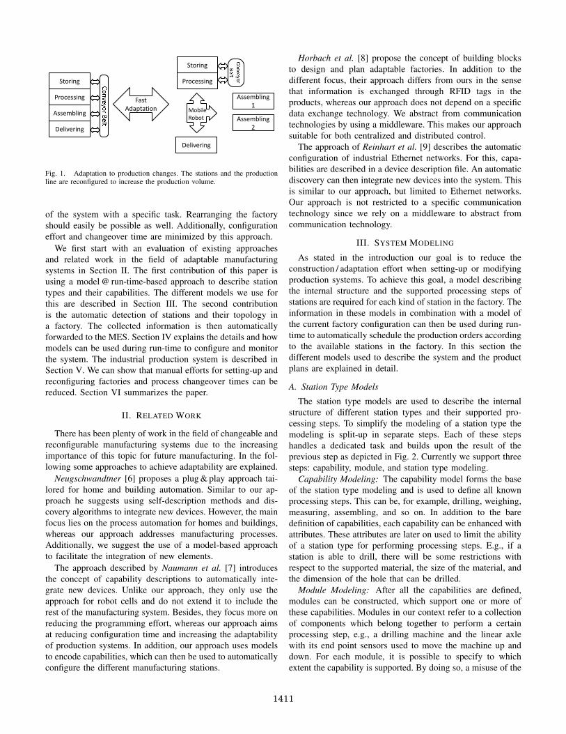
The suggested approach is based on the concept of mod-els @ run-time. In this concept, models are not only usedduring design time, but also during run-time. The system canitself change the models to reflect changes of the systemalso at modeling level. Tools can then calculate necessarymodifications on model level and trigger them at systemlevel. We suggest using models to describe manufacturingstations and their capabilities. Automatic station and topologydetection functions can build up a model of the factory atrun-time. The model of the whole factory with its stationsand the possible material flows is then used by the MES toautomatically calculate production schedules. To demonstratethe benefits of our approach, we use a modular productionsystem where mechatronic compatibility is already provided.With this approach a fast adaptation and reconfiguration asdescribed in Fig. 1 should be possible with minimal configu-ration effort on IT level. It should be possible to easily changethe production system to produce different products by addingand removing stations, which are a modular mechatronic part
Fig. 1. Adaptation to production changes. The stations and the productionline are reconfigured to increase the production volume.
of the system with a specific task. Rearranging the factoryshould easily be possible as well. Additionally, configurationeffort and changeover time are minimized by this approach.
We first start with an evaluation of existing approachesand related work in the field of adaptable manufacturingsystems in Section II. The first contribution of this paper isusing a model @ run-time-based approach to describe stationtypes and their capabilities. The different models we use forthis are described in Section III. The second contributionis the automatic detection of stations and their topology ina factory. The collected information is then automaticallyforwarded to the MES. Section IV explains the details and howmodels can be used during run-time to configure and monitorthe system. The industrial production system is described inSection V. We can show that manual efforts for setting-up andreconfiguring factories and process changeover times can bereduced. Section VI summarizes the paper.
II. RELATED WORK
There has been plenty of work in the field of changeable andreconfigurable manufacturing systems due to the increasingimportance of this topic for future manufacturing. In the fol-lowing some approaches to achieve adaptability are explained.
Neugschwandtner [6] proposes a plug & play approach tai-lored for home and building automation. Similar to our ap-proach he suggests using self-description methods and dis-covery algorithms to integrate new devices. However, the mainfocus lies on the process automation for homes and buildings,whereas our approach addresses manufacturing processes.Additionally, we suggest the use of a model-based approachto facilitate the integration of new elements.
The approach described by Naumann et al. [7] introducesthe concept of capability descriptions to automatically inte-grate new devices. Unlike our approach, they only use theapproach for robot cells and do not extend it to include therest of the manufacturing system. Besides, they focus more onreducing the programming effort, whereas our approach aimsat reducing configuration time and increasing the adaptabilityof production systems. In addition, our approach uses modelsto encode capabilities, which can then be used to automaticallyconfigure the different manufacturing stations.
Horbach et al. [8] propose the concept of building blocksto design and plan adaptable factories. In addition to thedifferent focus, their approach differs from ours in the sensethat information is exchanged through RFID tags in theproducts, whereas our approach does not depend on a specificdata exchange technology. We abstract from communicationtechnologies by using a middleware. This makes our approachsuitable for both centralized and distributed control.
The approach of Reinhart et al. [9] describes the automaticconfiguration of industrial Ethernet networks. For this, capa-bilities are described in a device description file. An automaticdiscovery can then integrate new devices into the system. Thisis similar to our approach, but limited to Ethernet networks.Our approach is not restricted to a specific communicationtechnology since we rely on a middleware to abstract fromcommunication technology.
III. SYSTEM MODELING
As stated in the introduction our goal is to reduce theconstruction / adaptation effort when setting-up or modifyingproduction systems. To achieve this goal, a model describingthe internal structure and the supported processing steps ofstations are required for each kind of station in the factory. Theinformation in these models in combination with a model ofthe current factory configuration can then be used during run-time to automatically schedule the production orders accordingto the available stations in the factory. In this section thedifferent models used to describe the system and the productplans are explained in detail.
A. Station Type Models
The station type models are used to describe the internalstructure of different station types and their supported pro-cessing steps. To simplify the modeling of a station type themodeling is split-up in separate steps. Each of these stepshandles a dedicated task and builds upon the result of theprevious step as depicted in Fig. 2. Currently we support threesteps: capability, module, and station type modeling.
Capability Modeling: The capability model forms the baseof the station type modeling and is used to define all knownprocessing steps. This can be, for example, drilling, weighing,measuring, assembling, and so on. In addition to the baredefinition of capabilities, each capability can be enhanced withattributes. These attributes are later on used to limit the abilityof a station type for performing processing steps. E.g., if astation is able to drill, there will be some restrictions withrespect to the supported material, the size of the material, andthe dimension of the hole that can be drilled.
Module Modeling: After all the capabilities are defined,modules can be constructed, which support one or more ofthese capabilities. Modules in our context refer to a collectionof components which belong together to perform a certainprocessing step, e.g., a drilling machine and the linear axlewith its end point sensors used to move the machine up anddown. For each module, it is possible to specify to whichextent the capability is supported. By doing so, a misuse of the
1411
Processing DeliveringDistributing
Processing
Transport
Conveyor BeltDrill
Drilling
Drill
Drilling
Transport
Conveyor Belt
Drilling
Transport
Fig. 2. Modeling of the station types and the production system. The grey arrows indicate the different modeling steps: Capabilities, modules, station types,and production systems with their stations.
module is prevented, because it is not possible to drill a 10 mmhole with a module which only supports holes with a diameterup to 8 mm. The modules also define their internal materialflow, which is afterwards used to ensure that a path existsbetween the different modules scheduled for the production.
Station Type Modeling: In the last step station types can beconstructed out of the previously defined modules as depictedin an example in Fig. 3.
Module Test Height
Module Drill
Attributes: Material plastic,
8mm hole
Module Lever
Module Rotary Table
Interaction Point
Fig. 3. The modules drill, test height, lever, and rotary table with theirrespective capabilities are combined to model the processing station type.Additionally, the station has two interaction points that define how this stationtype is connected to other station types.
We use model-to-metamodel (M2MM) transformations tocombine the different models [10], [11]. M2MM transforma-tions take model objects and create metamodel classes outof them. These classes can then be used to instantiate newobjects. In this sense, the capability model is used to createparts of the module metamodel and the module model isused to create parts of the station type metamodel. By usingM2MM transformations, changes in one model directly affectthe structure of subsequent models.
B. Factory Model
The factory model is used to represent the current factoryconfiguration. This includes what kind of stations are available,how many of them, and how they are connected to eachother. The stations can be either arranged in a line or asmanufacturing cells. In a line, one station is directly connectedto another station. When one station outputs a workpiece theother station will receive it as input. If they are arrangedas manufacturing cells, a material transportation system isused to fetch and deliver the workpieces. For example, thetransportation system can be a conveyor belt or a mobilerobot. In contrast to the other models, the factory model is
automatically constructed during run-time by the system toreflect the current situation in the factory. An example ofthe factory model of our demonstration setup is illustrated inFig. 4. The construction of the factory model during run-timeis described in more detail in Section IV.
DistributingTestingProcessing
DeliveringStoringAssembling
Co
nveyo
r Belt
Fig. 4. Stations and material flow used in the demonstration setup.
C. Product Plan Model
The last model is the product plan model, which specifieshow different goods are to be manufactured. A product planfor a specific good contains the required production steps andthe order in which they have to be performed. Productionsteps are attributed with properties, e.g., size and weight ofthe workpiece. This information is used to check whether aconcrete station is able to perform a certain processing stepon the current workpiece.
The station type model, the factory model, and the productplan model are then used to automatically schedule productorders in the factory and validate that all processing steps fora good can be performed in the current factory setup. If thevalidation fails, a message is triggered to inform the operatorsabout the cause of the problem. For example, a product cannotbe produced due to a missing transportation possibility fromone station to another. In this case, the operators would benotified about the missing link, so that they can work on asolution for this problem.
IV. MODELS @ RUN-TIME
This section describes how the capability model, the modulemodel, and the station type model are used during run-time
1412
to derive information about the factory and how to constructthe factory model. The factory model contains the informationneeded by the MES and has to be kept up-to-date to ensurecorrect and immediate production planning. The factory modelhas to reflect the state of the factory at every point in time. Tobuild up the factory model, two steps are required. In the firststep, information about available stations and their types isgathered. How the available stations are connected with eachother is then determined in the second step. In the followingthese steps are described.
A. Station Detection
To have an up-to-date model of the current factory setup, thesystem needs to be informed about new as well as no longerexisting stations. This information is then stored in the factorymodel described in Section III. To reduce manual efforts,this step is done automatically. The stations periodically sendliveness notifications containing their station identifier to themaster control system. The master control system manages allreceived liveness notifications within a given period of timeand checks for new stations. It additionally checks whetherit has received a liveness notification from all known stationsto detect station breakdowns. If a station is in an error stateor a maintenance state, it can also indicate this to the mastercontrol system through defined signals. The factory model isupdated according to the observed station states. This ensuresthat the factory model only includes stations that are availableand ready for production preventing production time loss. Inaddition, when a new station is detected the system asks thenew station about its type. The type is used during planningto reason about the production steps that can be performed bythe station. All the information is then forwarded to the MESto adapt the planning to the current factory setup.
Currently, different strategies are supported to detect sta-tions. Either a station is capable of sending a liveness notifi-cation directly to the master control system informing it aboutits existence or the master control system has to periodicallypoll for stations. The concrete realization depends on theused hardware controllers and communication technologies,but most communication technologies provide the possibilityto list all connected communication participants.
To lower resource requirements on used controllers, thestation type is encoded via a unique station type identifier.This identifier can be used to look-up the related station typedescription. On powerful controllers it is even imaginable tostore the station type description directly in the controller andsend it to the master control system on demand.
B. Topology Detection
In order to generate valid production schedules, knowledgeabout the setup of the factory has to be present. This setuprefers to the position of stations as well as their connectionsto each other within the factory. The position provides infor-mation about neighboring stations if the stations are arrangedin a line. If a material transport system, such as a mobile robotor a conveyor belt, is used, the topology additionally includes
all stations that can use the material transport system and theirattachment points. Acquiring information about the topologyof a production system enables reasoning about possiblematerial flows in the production system. The material flowinformation can then be used to generate feasible schedulesfor the production.
To reduce manual effort, we suggest an approach for au-tomatically detecting the topology of a production system.For this, we add a neighborhood detection state in the controlprogram of every station. A station can switch to the neigh-borhood detection state whenever its current state allows fora short interruption. The stations are interrupted to preventany damages of produced goods or the used infrastructure.Alternatively, the topology detection can be performed inparallel to the production process, if the station controllersallow this. The detection consists of three steps:
1) Switch to neighborhood detection state2) Start discovery algorithm3) Update factory model
Whenever a new station is integrated into the system, themaster control system signals to all involved controllers thata switch to the neighborhood detection state is necessary. Theswitching signal from the master control system does nothave to occur immediately after a new station is integrated.Typically, the system would wait for a short while to checkwhether other stations are also integrated to perform thetopology detection only once for several stations. As a result,production downtimes are kept at a minimum. As soon asall the stations have entered the neighborhood detection state,the topology can be determined. To prevent a complete stopof the production, only stations that might be affected bythe change need to be notified and triggered to switch tothe neighborhood detection state. The affected stations arethe ones belonging to the same production line or productionhall. The discovery is achieved by sending out neighborhooddetection signals and determining the receivers of the signals.In our case we use an optical connection between the stations.This connection consists of an infrared light emitter connectedto one station and a corresponding receiver attached to anotherstation. Other possible solutions could be hard wired ordedicated plug connections between stations attached to theirinteraction points. When a mobile robot is part of the materialtransport system used in the factory, the robot can be usedfor the topology detection as well. The robot starts searchingfor available stations in the defined production area to gathertopology information. Each station has a unique identificationmark through which the robot can identify the type of thestation. The robot then stores the location of the station andbuilds up a map of the factory. A reachable station indicatesthat the robot can be used to fetch / deliver workpieces from / tothis station. In our scenario we use optical markers as uniqueIDs, but RFID tags or other techniques can be used as well.If a station has no neighbors yet or cannot be reached bya mobile robot, no information about the topology is inferredand the station is considered isolated. When the discovery step
1413
is done, the acquired information is used to update the dataset in the MES to reflect the current factory setup.
To have a complete model of possible material flows,information about whether a material flow is bidirectionalor unidirectional is required. Furthermore, the direction ofunidirectional connections is required. This information cannotbe retrieved through topology detection only. Instead, the typeof the station and the information encoded in the correspond-ing station type model can be used to determine possibledirections of the material flow. This is achieved by defininginteraction points. Interaction points are places where materialcan be exchanged between stations. Their definition specifiesif they can be used as input points, output points, or both.To determine the possible material flow between two stations,the corresponding interaction points have to be looked-up tocalculate the feasible material flow. Thereby, it is possibleto detect misconfigurations, e.g., the interaction points of theconnected stations are both only input points.
For example, if we connect a processing station to a con-veyor belt, the topology detection would only know that theyare connected without knowing the supported directions formaterial exchange. By looking-up the used interaction pointsin the corresponding station types it can determine that bothare defined as in- and output, which results in a bidirectionalmaterial flow.
C. Integration with the Manufacturing Execution System
The factory model is used to update the data set used by theMES. Together with the production plan model it is the foun-dation for the planning performed by the MES. The MES hasthe information about available stations from the factory modeland can thus look-up which operations can be performedby the current configuration. Additionally, it decides whichoperations are scheduled on which machine. If several stationscan perform an operation, the MES schedules the fittest one.Fitness varies depending on system-defined criteria. Possiblecriteria are, for example, makespan, utilization rate, energyefficiency, delivery time, or combinations of them. However,optimizing scheduling algorithms computed by the MES is avery challenging task and is computationally hard. There is alot of research in this area and the topic is beyond the scope ofthis paper. Apart from these criteria, the MES has to choose aset of stations that are all connected to each other to ensure thata material flow is possible. The required operations to producea certain product can be obtained from the product plan model.Using this information together with the topology information,the MES can search the solution space to match requiredoperations with available operations while adding necessarytransport operations in-between. During the calculation of theproduction schedule, the MES ensures that the next operationis only scheduled on a machine that can be reached from theprevious one. This guarantees feasible schedules with respectto material flow. After planning the production, the MES sendsthe processing instructions to the selected stations, and hencestarts the production. Details of this process are out of scopeof this paper.
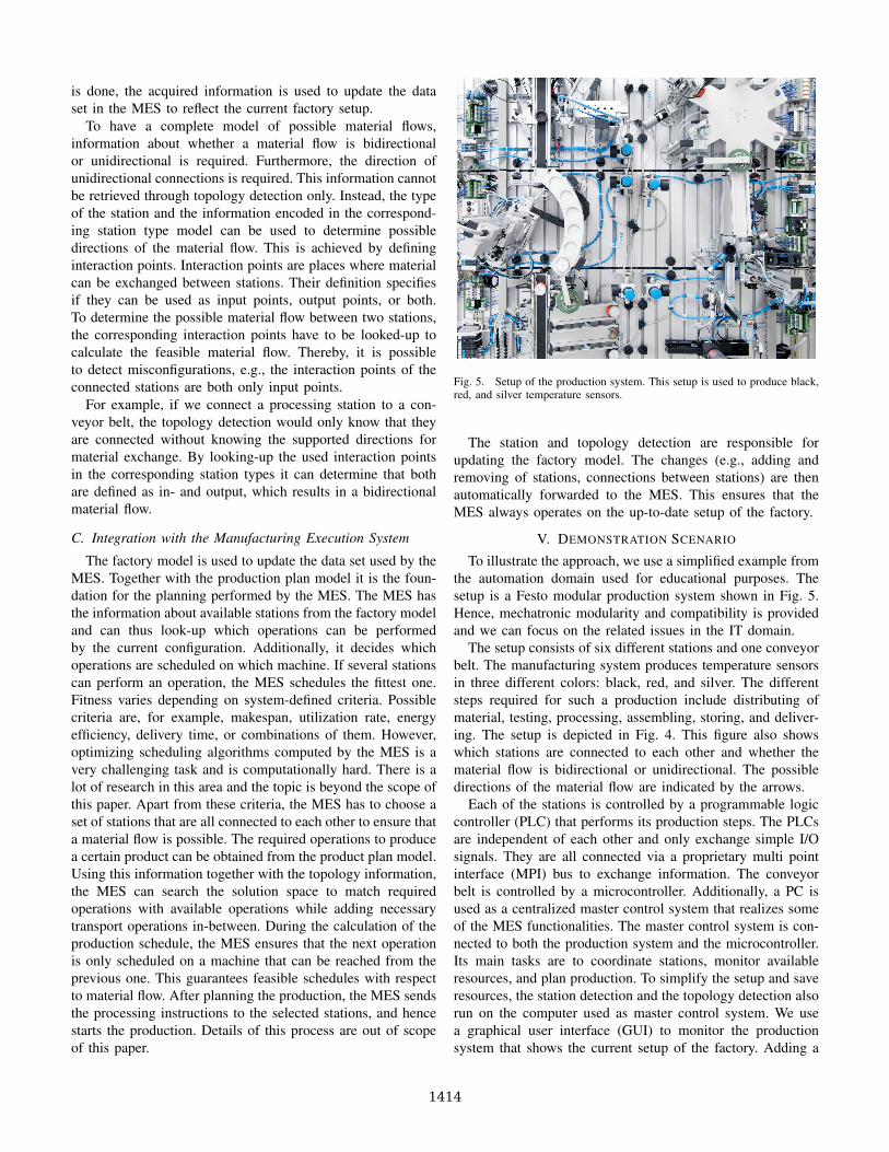
Fig. 5. Setup of the production system. This setup is used to produce black,red, and silver temperature sensors.
The station and topology detection are responsible forupdating the factory model. The changes (e.g., adding andremoving of stations, connections between stations) are thenautomatically forwarded to the MES. This ensures that theMES always operates on the up-to-date setup of the factory.
V. DEMONSTRATION SCENARIO
To illustrate the approach, we use a simplified example fromthe automation domain used for educational purposes. Thesetup is a Festo modular production system shown in Fig. 5.Hence, mechatronic modularity and compatibility is providedand we can focus on the related issues in the IT domain.
The setup consists of six different stations and one conveyorbelt. The manufacturing system produces temperature sensorsin three different colors: black, red, and silver. The differentsteps required for such a production include distributing ofmaterial, testing, processing, assembling, storing, and deliver-ing. The setup is depicted in Fig. 4. This figure also showswhich stations are connected to each other and whether thematerial flow is bidirectional or unidirectional. The possibledirections of the material flow are indicated by the arrows.
Each of the stations is controlled by a programmable logiccontroller (PLC) that performs its production steps. The PLCsare independent of each other and only exchange simple I/Osignals. They are all connected via a proprietary multi pointinterface (MPI) bus to exchange information. The conveyorbelt is controlled by a microcontroller. Additionally, a PC isused as a centralized master control system that realizes someof the MES functionalities. The master control system is con-nected to both the production system and the microcontroller.Its main tasks are to coordinate stations, monitor availableresources, and plan production. To simplify the setup and saveresources, the station detection and the topology detection alsorun on the computer used as master control system. We usea graphical user interface (GUI) to monitor the productionsystem that shows the current setup of the factory. Adding a
1414
physical station to the factory is immediately reflected in theGUI as a new node annotated with the corresponding stationtype. Whenever a station is removed from the system, thecorresponding node is removed in the GUI, validating that thefactory model has been updated correctly.
To update the factory model of the MES, the stationdetection and the topology detection have to communicatewith the MES. Since we support different platforms, we use amiddleware to abstract from communication technology. Thus,they can run on the same machine or can be distributedon several machines. The middleware is used for verticalcommunication from MES to shop floor (e.g., the differentcontrollers of the stations). The horizontal communicationbetween different elements of the system, such as the dif-ferent stations or the MES and the GUI, is handled bythe middleware as well. Using the middleware, we supportdifferent platforms creating a heterogeneous setup. The con-trollers can be PLCs, microcontrollers, industrial computers,or standard PCs. Moreover, heterogeneous communicationinterfaces such as Ethernet and MPI through a gateway canbe used. We use the CHROMOSOME middleware1 for thispurpose. CHROMOSOME is a data-centric middleware with apublish-subscribe concept that abstracts from specific sendersand receivers. Publication and subscription information ispropagated through the system and corresponding routes areestablished through the middleware. This reduces the effortof configuring communication channels manually and enablesthe plug & play concept at communication level.
In addition, we support virtual stations that include thesoftware part but are not connected physically to the system.This setup allows testing different scenarios and facilitatesanalyzing the plug & play concept without having to movethe physical stations around. The virtual stations are alsoconnected to the master control system and communicatewith it through the middleware.
Evaluation: With this demonstration setup we show thatheterogeneous platforms can be integrated into a system andconfigured for use in the factory. Without any manual effort,new stations are added to the data set of the MES and areautomatically integrated into the planning system as soon asthey show up. By using models to describe capabilities andtopologies, all the required information is easily accessible bythe MES for reasoning and production schedule generationwithout further interaction with the operators. The engineerhas to define a station type model only once for each type ofstation and can reuse them in different systems and factories.This reduces setup time of production systems resulting infaster process changeover times. Since the models, the stationdetection, and topology detection are reusable, the configu-ration effort is less error-prone, which further reduces theconfiguration time. Moreover, the engineer can focus on thedesign of the control of the factory and no longer has to worryabout each configuration step.
Since the factory model reflects the current factory con-figuration at each point in time, the MES can quickly reactto machine breakdowns and changes in the manufacturingsystem. This can be done without any further configurationeffort making the system more adaptable.
VI. CONCLUSION
In this paper we proposed a models @ run-time-based ap-proach to enable plug & play in the automation industry at ITlevel. This approach helps reducing manual efforts of setting-up and reconfiguring manufacturing systems making themmore adaptable to changes. We presented how models can beused to describe capabilities of stations. Furthermore, thesemodels are then used during run-time to reflect the currentsetup of the factory. The MES can then use this information formonitoring the setup of the system and planning the productionschedule. We used a simplified industrial setup to show howour approach can be applied. This setup demonstrates thatwe support heterogeneous platforms with our approach andthat we abstract away from different communication interfacesby using a middleware. Furthermore, the manual efforts werereduced, since all the steps required for configuring or re-configuring the system were done automatically during thedetection cycles, which we proposed in this paper.
REFERENCES
[1] H.-P. Wiendahl, H. ElMaraghy, P. Nyhuis, M.-F. Zah, H.-H. Wiendahl,N. Duffie, and M. Brieke, “Changeable Manufacturing – Classification,Design and Operation,” CIRP Annals-Manufacturing Technology, 2007.
[2] M.-F. Zah, M. Beetz, K. Shea, G. Reinhart, O. Stursberg, M. Ostgathe,C. Lau, C. Ertelt, D. Pangercic, T. Ruhr et al., “An Integrated Approachto Realize the Cognitive Machine Shop,” in Proceedings of the 1stInternational Workshop on Cognition for Technical Systems.
[3] O. Sauer and J. Jasperneite, “Adaptive information technology in man-ufacturing,” in CIRP Conference on Manufacturing Systems, Madison,WI, USA, Jun 2011.
[4] B. Vogel-Heuser, G. Kegel, K. Bender, and K. Wucherer, “GlobalInformation Architecture for Industrial Automation,” atp, 2009.
[5] Cyber-Physical Systems: Driving Force for Innovation in Mobility,Health, Energy and Production, ser. acatech Position. acatech –National Academy of Science and Engineering, 2011.
[6] G. Neugschwandtner, “Towards Plug and Play in Home and BuildingAutomation Networks,” in IEEE Conference on Emerging Technologiesand Factory Automation. ETFA’06. IEEE, 2006, pp. 461–464.
[7] M. Naumann, K. Wegener, and R. Schraft, “Control Architecture forRobot Cells to Enable Plug’n’Produce,” in IEEE International Confer-ence on Robotics and Automation. IEEE, 2007, pp. 287–292.
[8] S. Horbach, J. Ackermann, E. Muller, and J. Schutze, “Building Blocksfor Adaptable Factory Systems,” Robotics and Computer-IntegratedManufacturing, 2011.
[9] G. Reinhart, S. Krug, S. Huttner, Z. Mari, F. Riedelbauch, and M. Schlo-gel, “Automatic Configuration (Plug & Produce) of Industrial EthernetNetworks,” in 9th IEEE/IAS International Conference on Industry Ap-plications (INDUSCON). IEEE, 2010, pp. 1–6.
[10] G. Kainz, C. Buckl, S. Sommer, and A. Knoll, “Model-to-MetamodelTransformation for the Development of Component-Based Systems,”in Model Driven Engineering Languages and Systems, ser. LectureNotes in Computer Science, D. Petriu, N. Rouquette, and y. Haugen,Eds. Springer Berlin / Heidelberg, 2010, vol. 6395, pp. 391–405,10.1007/978-3-642-16129-2 28.
[11] G. Kainz, C. Buckl, and A. Knoll, “Automated Model-to-MetamodelTransformations Based on the Concepts of Deep Instantiation,” in ModelDriven Engineering Languages and Systems, ser. Lecture Notes inComputer Science, J. Whittle, T. Clark, and T. Khne, Eds. SpringerBerlin / Heidelberg, 2011, vol. 6981, pp. 17–31, 10.1007/978-3-642-24485-8 3.