TERRIFIC Towards Enhanced Integration of Design and Production in the Factory of the Future through Isogeometric Technologies September 1, 2011 - August 31, 2014 www.terrific-project.eu European Community’s Seventh Framework Programme Grant Agreement 284981 Call FP7-2011-NMP-ICT-FoF TERRIFIC and ISO 10303 STEP Kjell Bengtsson Jotne, Norway [email protected]www.jotne.com
Transcript
TERRIFICTowards Enhanced Integration of Design and
Production in the Factory of the Future through Isogeometric Technologies
September 1, 2011 - August 31, 2014www.terrific-project.eu
European Community’s Seventh Framework ProgrammeGrant Agreement 284981
Call FP7-2011-NMP-ICT-FoF
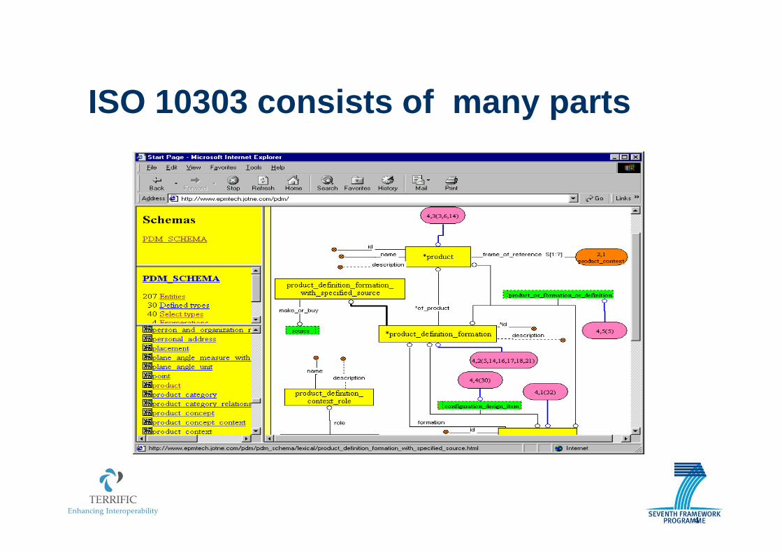
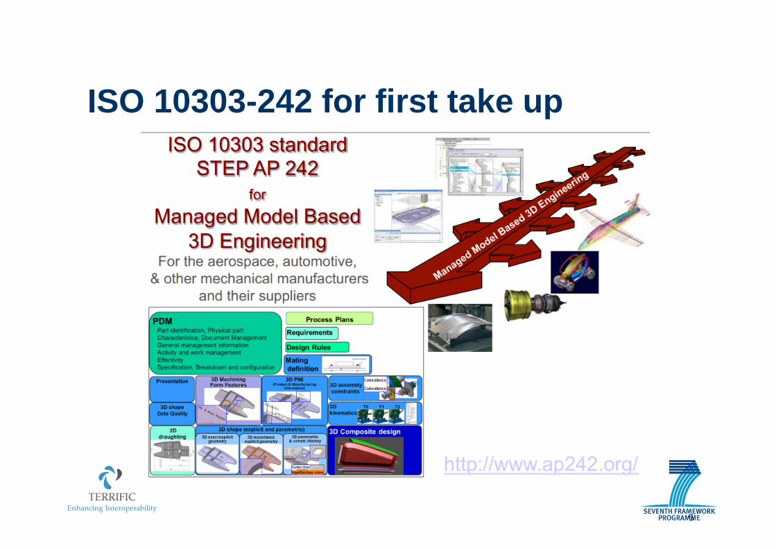
TERRIFIC and ISO 10303 STEPKjell Bengtsson Jotne, Norway
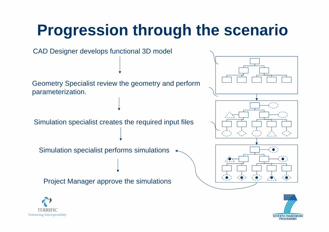
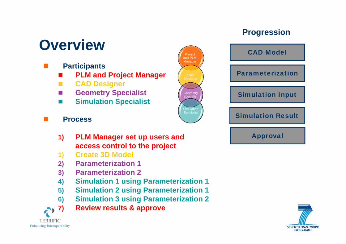
1) PLM Manager set up users and access control to the project
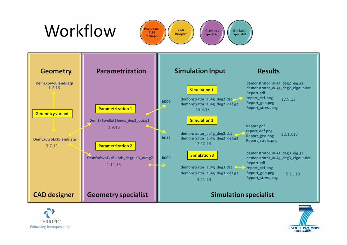
1) Create 3D Model2) Parameterization 13) Parameterization 24) Simulation 1 using Parameterization 15) Simulation 2 using Parameterization 16) Simulation 3 using Parameterization 27) Review results & approve
CAD Model
Parameterization
Simulation Input
Simulation Result
Progression
Project and PLM Manager
CAD Designer
Geometry specialist
Simulation Specialist
Approval
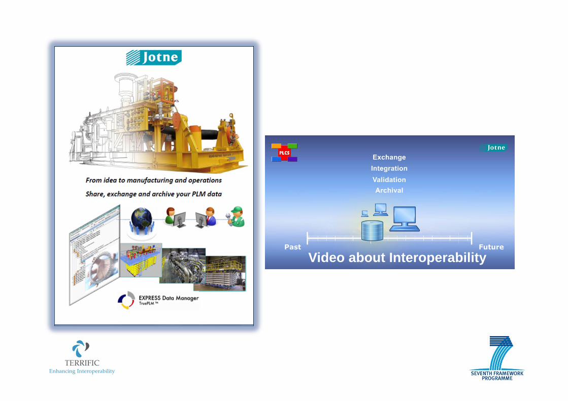
What is TruePLM?
EDMmodel Server™(plcs)
data
data
data
datadata
data
dataDEX
Data ExchangeSpecification
(PLCS)
0
A
B C
D
E
F
TruePLM
Business cases – Life‐cycle support / Interoperability
Subcontractors and partners
Phase 0 Mission analysis/needs identificationPhase A FeasibilityPhase B Preliminary DefinitionPhase C Detailed DefinitionPhase D Qualification and ProductionPhase E UtilizationPhase F Disposal
TruePLM main functionalities
Product structure tree: TruePLM provides a product-structure-based way for sharing of project data, team collaboration and long-term archiving tools.
Project lifetime scope: TruePLM system supports the project activities across all the phases from conceptual design until the end of the project.
Configuration control tool: TruePLM has in built configuration control tool to manage the different versions of the product structure and data related to it
Presentation of product data in tree structures: All product data sin TruePLM is always related to the product structure tree, and presented in such a tree structure
Versioning of data: TruePLM system supports versioning of project data
Search for product data: TruePLM supports searching of project data and project documents within the product tree
User access control: Access to the TruePLM system is limited by a login system. Access to the projects and project data is limited according to the type of users and permissions required and assigned to him or her.
TruePLM main functionalities (2)
Traceability of the history of data: TruePLM system tracks the history of the different version submitted to the system during the development of the project
Integration with specific project tools: TruePLM allows viewing and editing of files with specific data contents to be opened in specific application
Archival of project data: TruePLM includes an archival system with the following capabilities: - archival of standard representation of integrated life cycle data for space products
including not only the initial phases, but also design and engineering as well as operational and logistics aspects of a space system according to ISO 10303, STEP.
- long term storage of structured space product data including referenced documents according to ISO 14721, OAIS.
Project plan information: TruePLM stores basic information about the project plan: - planned milestones - scheduled events - planned actions
TruePLM main functionalities (3)
Baselines: TruePLM allows the creation of baselines of all or part of the project data at any moment, and also relating baselines to milestones if required A Baseline is defined as the approved state of the product structure at a key
milestone of the programme or project and provides the point of departure for further evolution of the project or programme.
Project data contents: TruePLM allows storing of project data in form of files, including documents, CAD files, manuals, structured documents, etc.
Data dependency representation: TruePLM allows management of dependencies between documents / data, in order to identify, check and correct the possible effect of changes in requirements or project data.
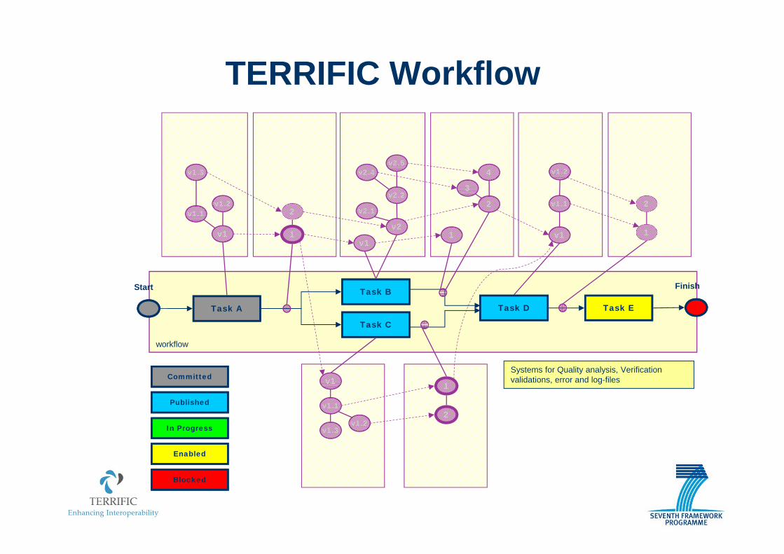
TERRIFIC Process Status
Committed
Published
In Progress
Enabled
Blocked
workflow
Task A Task D Task E
Start FinishTask B
Task C
Task has Finished, Issued Data
Task has Started, Intermediate Data Exported to Other Tasks
Task has Started, Data Available within Task
Task Ready to Start, Input Data Available
Task Waiting for Input Data to Become Available
Who PLM and Project Manager
Setting up project resources and PLM server
Logon as sys admin in TruePLM server system Select predefined tasks and create activities Link tasks (assign workflow order and data) Assign tools, as required Store workflow as notification
TERRIFIC Workflow Definition
Project and PLM Manager
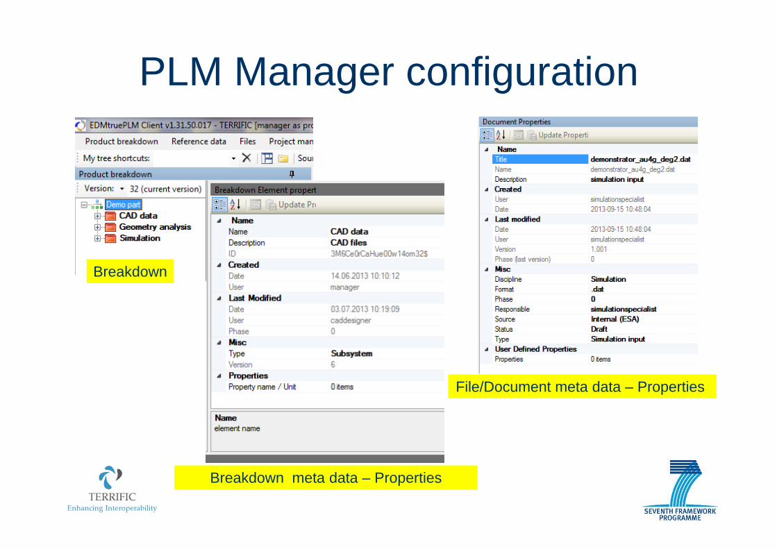
PLM Manager configuration
Breakdown
File/Document meta data – Properties
Breakdown meta data – Properties
CAD DESIGNERCREATES
THE 3D MODEL
workflow
Task A
Task B
Task C
Task E
Start Finish
Committed
Published
In Progress
Enabled
Blocked
TERRIFIC Process Execution (1)
Task D
Systems for Quality analysis, Verificationvalidations, error and log-files
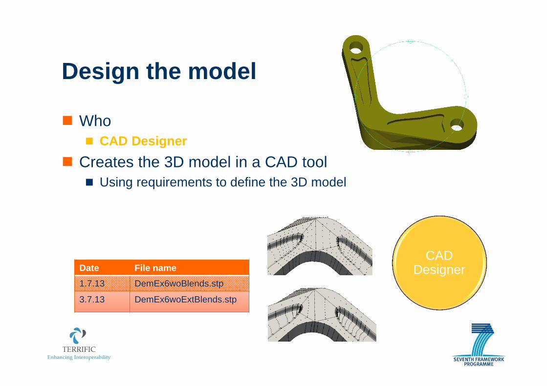
Who CAD Designer
Creates the 3D model in a CAD tool Using requirements to define the 3D model
Design the model
CAD DesignerDate File name
1.7.13 DemEx6woBlends.stp
3.7.13 DemEx6woExtBlends.stp
CAD Designer
workflow
Task A
Task B
Task C
v1
v1.2v1.1
v1.3
Task E
Start Finish
Committed
Published
In Progress
Enabled
Blocked
TERRIFIC Process Execution (2)
Task D
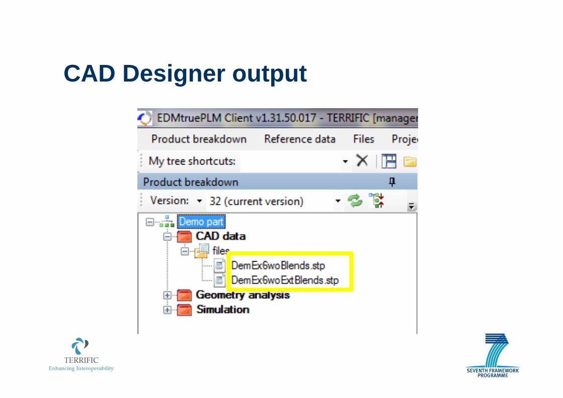
The CAD designer may create several versions of the design
Systems for Quality analysis, Verificationvalidations, error and log-files
CAD Designer output
Geometry Specialistwork-in-progress
Parameterization Version 2
CAD Designer 3D modelpublished data
workflow
Task A
Task B
Task C
v1
v1.2v1.1
v1.3
1
Task E
Start Finish
Committed
Published
In Progress
Enabled
Blocked
TERRIFIC Process Execution (3)
Task D
Geometry Specialistwork-in-progress
Parameterization Version 1
Systems for Quality analysis, Verificationvalidations, error and log-files
Who Geometry Specialist
Update the 3D model in GoTools Refine the Geometry
Parameterization of the model
Geometry specialistDate File name
1.9.13 DemEx6woExtBlends_deg2_out.g2
1.11.13 DemEx6woExtBlends_degree3_out.g2
Need graphics showing parameterizations (*2)
3D modelpublished data
Parameterization Version 2
Parameterization Version 1
Parameterizedpublished data
System Engineeringwork-in-progress
workflow
Task A
Task B
Task C
v1
v1.2v1.1
v1.3
1
2
v2
v2.1
v2.2
v2.5v2.4
v1
v1.1
v1.3v1.2
2
1
v1
Task E
Start Finish
Committed
Published
In Progress
Enabled
Blocked
TERRIFIC Process Execution (4)
Task D
Systems for Quality analysis, Verificationvalidations, error and log-files
Geometry Specialist output
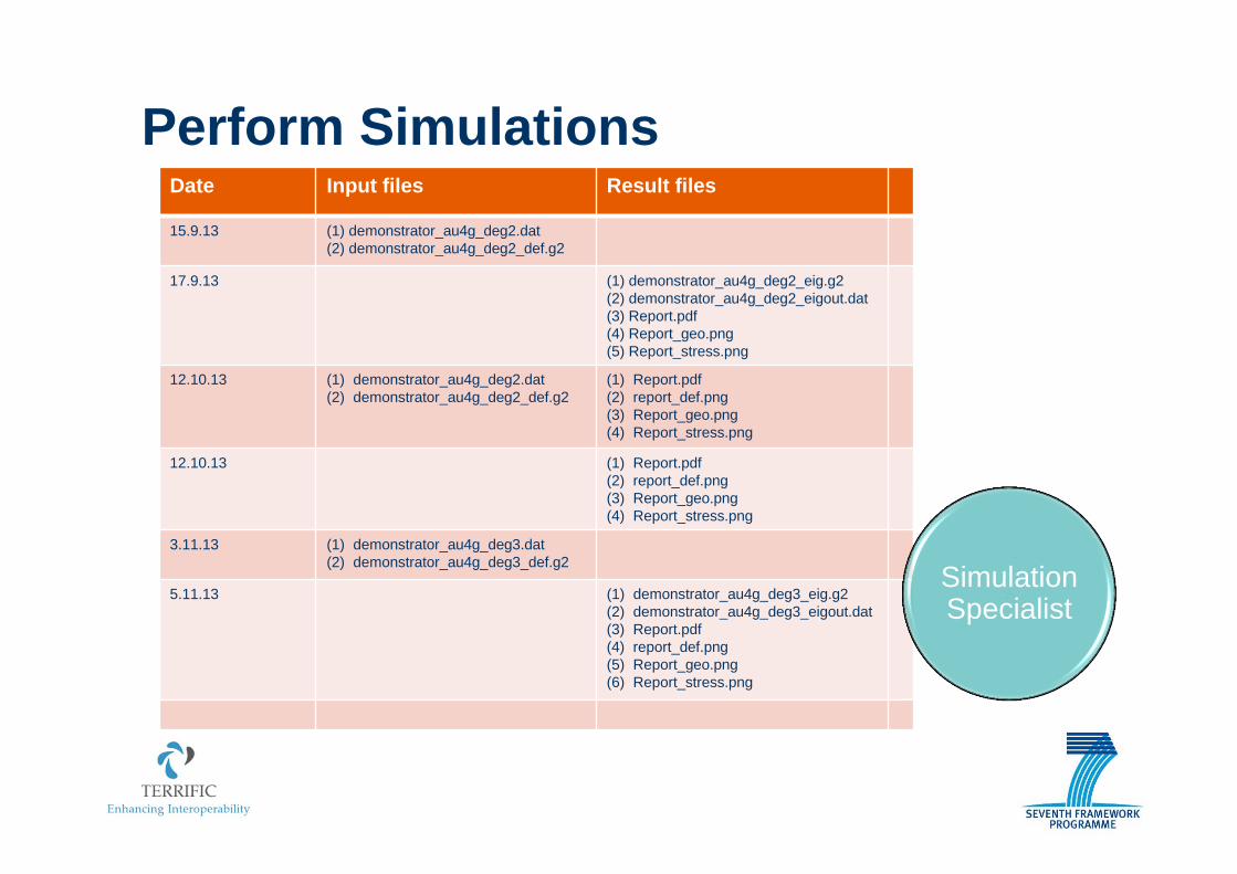
Perform Simulations
Who Simulation Specialist
Creates the input files Collect material properties Define load cases Perform simulations