Towards the Humanoid Robot Butler Caitlin Lagrand Universiteit van Amsterdam Email: [email protected]Michiel van der Meer Universiteit van Amsterdam Email: [email protected]Abstract—This project focuses on detecting a tomato in a kitchen environment and grabbing it from the table. The ROS framework is used for the implementation of this project. Three detection algorithms are discussed to best detect the tomato. Also a localization algorithm is defined to determine the location of the tomato. The ROS library MoveIt is used for its inverse kinematics to grab the tomato from the table. 1. Introduction The use of robots has been increasing over the last years. Not only in the industry, but also in social sectors, such as health care or education. This project focuses on finding ways to apply the help of robots in a domestic environment. It is inspired by the HUMABOT Challenge of 2014 [1]. In this challenge, the kitchen is used as the environment where a robot has to perform the following tasks: • The safety task: one of the burners in the kitchen is lit and the robot has to turn it off. • The shopping list: identify missing objects on the shelves to make a shopping list. • The roasted tomato: identify a tomato and put it into a pan. This project focuses on “The roasted tomato” task. Section 2 will discuss previous research. In section 3, the used methods will be explained. Section 4 will demonstrate the different simulations that were used. In section 5 the results will be shown. Section 6 will evaluate the project and discuss ideas for future research. Section 7 will sum up the project and conclude. 2. Previous research This section discusses previous research. Two previously done researches were used: the Cognitive Image Processing (CIP) and some research from previous competitors of the HUMABOT Challenge. 2.1. Cognitive Image Processing (CIP) Ras [2] used a series of filters and detectors to maximize the accuracy when finding spherical objects. Since the de- tection is color invariant, the program would be able to find objects more dynamically. In short, it tries to find edges in a blurred image from the saturation channel of the original image. After detecting these edges, the user ends up with a binary image, with the outlines of objects highlighted if the recognition worked correctly. These binary images are then searched for any round shapes using blob detectors. Section 3.1.3 explains how this works. Eventually, a heavily modified version of the CIP-module was considered as one of the three main detectors. 2.2. Previous competitors Since the HUMABOT Challenge was held in 2014, the teams have no incentive to keep their code private any longer. One of the teams, NAO-UPC, made their implemen- tation publicly available on Github 1 . Even though the team did not complete the challenge, the team’s code provided some insights into OpenCV. Their low scores were most likely caused by a very conservative approach to localization and grasping objects. The localization required markers, which indicate the different pieces of furniture in the envi- ronment. This means that if the markers were either missing or misplaced, the robot would stop functioning properly. 3. Method The robot used in this research is the NAO from Alde- baran 2 . The NAO is a 50 cm tall humanoid robot. The envi- ronment is the standard play kitchen from IKEA including all the tools and vegetables (see Figure 1). The ROS framework [3] was used to give access to the many tools and libraries it has and, most importantly, to the MoveIt library [4]. MoveIt introduces a number of tools that aim to create developer-friendly software for mobile manipulation. This library, among other things, incorporates kinematics, motion planning and execution. To process im- ages, the OpenCV library [5] is used. All of these libraries are available in both Python and C++. The code presented with this paper is written in Python. All of our code is available at our Github repository 3 . 1. https://github.com/gerardcanal/NAO-UPC 2. https://www.aldebaran.com/en/cool-robots/nao 3. https://github.com/Caiit/tomato tracker py
Abstract—This project focuses on detecting a tomato in akitchen environment and grabbing it from the table. The ROSframework is used for the implementation of this project.Three detection algorithms are discussed to best detect thetomato. Also a localization algorithm is defined to determinethe location of the tomato. The ROS library MoveIt is usedfor its inverse kinematics to grab the tomato from the table.
1. Introduction
The use of robots has been increasing over the last years.Not only in the industry, but also in social sectors, suchas health care or education. This project focuses on findingways to apply the help of robots in a domestic environment.It is inspired by the HUMABOT Challenge of 2014 [1]. Inthis challenge, the kitchen is used as the environment wherea robot has to perform the following tasks:
• The safety task: one of the burners in the kitchen islit and the robot has to turn it off.
• The shopping list: identify missing objects on theshelves to make a shopping list.
• The roasted tomato: identify a tomato and put it intoa pan.
This project focuses on “The roasted tomato” task.Section 2 will discuss previous research. In section 3, theused methods will be explained. Section 4 will demonstratethe different simulations that were used. In section 5 theresults will be shown. Section 6 will evaluate the projectand discuss ideas for future research. Section 7 will sum upthe project and conclude.
2. Previous research
This section discusses previous research. Two previouslydone researches were used: the Cognitive Image Processing(CIP) and some research from previous competitors of theHUMABOT Challenge.
2.1. Cognitive Image Processing (CIP)
Ras [2] used a series of filters and detectors to maximizethe accuracy when finding spherical objects. Since the de-tection is color invariant, the program would be able to find
objects more dynamically. In short, it tries to find edges ina blurred image from the saturation channel of the originalimage. After detecting these edges, the user ends up witha binary image, with the outlines of objects highlighted ifthe recognition worked correctly. These binary images arethen searched for any round shapes using blob detectors.Section 3.1.3 explains how this works. Eventually, a heavilymodified version of the CIP-module was considered as oneof the three main detectors.
2.2. Previous competitors
Since the HUMABOT Challenge was held in 2014, theteams have no incentive to keep their code private anylonger. One of the teams, NAO-UPC, made their implemen-tation publicly available on Github 1. Even though the teamdid not complete the challenge, the team’s code providedsome insights into OpenCV. Their low scores were mostlikely caused by a very conservative approach to localizationand grasping objects. The localization required markers,which indicate the different pieces of furniture in the envi-ronment. This means that if the markers were either missingor misplaced, the robot would stop functioning properly.
3. Method
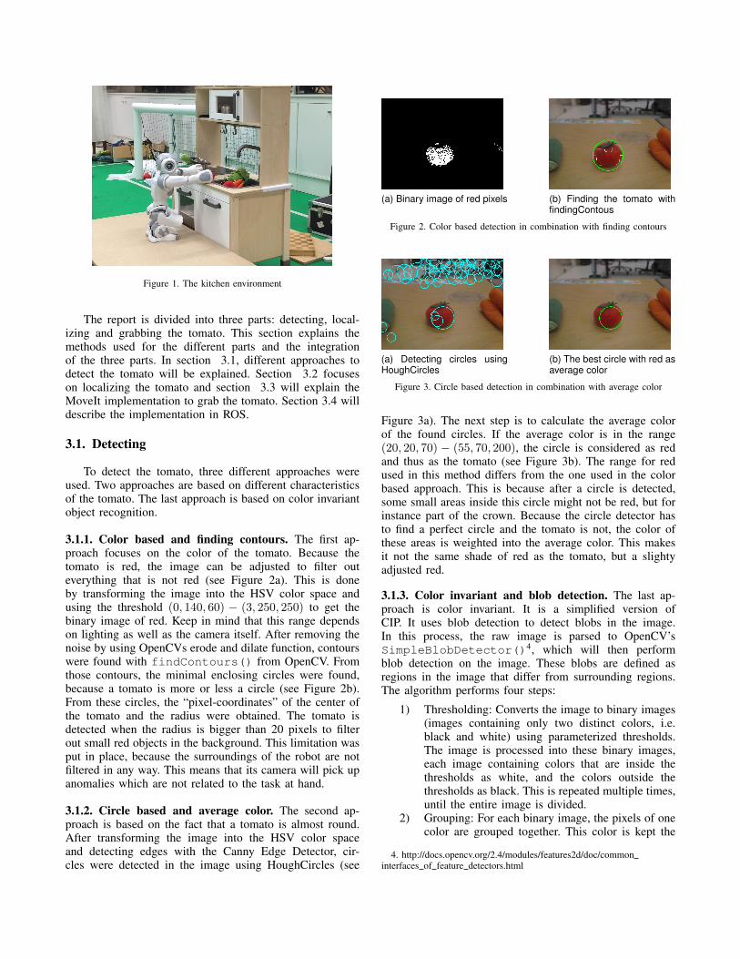
The robot used in this research is the NAO from Alde-baran2. The NAO is a 50 cm tall humanoid robot. The envi-ronment is the standard play kitchen from IKEA includingall the tools and vegetables (see Figure 1).
The ROS framework [3] was used to give access to themany tools and libraries it has and, most importantly, to theMoveIt library [4]. MoveIt introduces a number of toolsthat aim to create developer-friendly software for mobilemanipulation. This library, among other things, incorporateskinematics, motion planning and execution. To process im-ages, the OpenCV library [5] is used. All of these librariesare available in both Python and C++. The code presentedwith this paper is written in Python. All of our code isavailable at our Github repository 3.
The report is divided into three parts: detecting, local-izing and grabbing the tomato. This section explains themethods used for the different parts and the integrationof the three parts. In section 3.1, different approaches todetect the tomato will be explained. Section 3.2 focuseson localizing the tomato and section 3.3 will explain theMoveIt implementation to grab the tomato. Section 3.4 willdescribe the implementation in ROS.
3.1. Detecting
To detect the tomato, three different approaches wereused. Two approaches are based on different characteristicsof the tomato. The last approach is based on color invariantobject recognition.
3.1.1. Color based and finding contours. The first ap-proach focuses on the color of the tomato. Because thetomato is red, the image can be adjusted to filter outeverything that is not red (see Figure 2a). This is doneby transforming the image into the HSV color space andusing the threshold (0, 140, 60) − (3, 250, 250) to get thebinary image of red. Keep in mind that this range dependson lighting as well as the camera itself. After removing thenoise by using OpenCVs erode and dilate function, contourswere found with findContours() from OpenCV. Fromthose contours, the minimal enclosing circles were found,because a tomato is more or less a circle (see Figure 2b).From these circles, the “pixel-coordinates” of the center ofthe tomato and the radius were obtained. The tomato isdetected when the radius is bigger than 20 pixels to filterout small red objects in the background. This limitation wasput in place, because the surroundings of the robot are notfiltered in any way. This means that its camera will pick upanomalies which are not related to the task at hand.
3.1.2. Circle based and average color. The second ap-proach is based on the fact that a tomato is almost round.After transforming the image into the HSV color spaceand detecting edges with the Canny Edge Detector, cir-cles were detected in the image using HoughCircles (see
(a) Binary image of red pixels (b) Finding the tomato withfindingContous
Figure 2. Color based detection in combination with finding contours
(a) Detecting circles usingHoughCircles
(b) The best circle with red asaverage color
Figure 3. Circle based detection in combination with average color
Figure 3a). The next step is to calculate the average colorof the found circles. If the average color is in the range(20, 20, 70) − (55, 70, 200), the circle is considered as redand thus as the tomato (see Figure 3b). The range for redused in this method differs from the one used in the colorbased approach. This is because after a circle is detected,some small areas inside this circle might not be red, but forinstance part of the crown. Because the circle detector hasto find a perfect circle and the tomato is not, the color ofthese areas is weighted into the average color. This makesit not the same shade of red as the tomato, but a slightyadjusted red.
3.1.3. Color invariant and blob detection. The last ap-proach is color invariant. It is a simplified version ofCIP. It uses blob detection to detect blobs in the image.In this process, the raw image is parsed to OpenCV’sSimpleBlobDetector()4, which will then performblob detection on the image. These blobs are defined asregions in the image that differ from surrounding regions.The algorithm performs four steps:
1) Thresholding: Converts the image to binary images(images containing only two distinct colors, i.e.black and white) using parameterized thresholds.The image is processed into these binary images,each image containing colors that are inside thethresholds as white, and the colors outside thethresholds as black. This is repeated multiple times,until the entire image is divided.
2) Grouping: For each binary image, the pixels of onecolor are grouped together. This color is kept the
4. http://docs.opencv.org/2.4/modules/features2d/doc/commoninterfaces of feature detectors.html
Figure 4. Detecting the tomato using the blobDetector
same across multiple binary images. The centers ofthese blobs are calculated.
3) Merging: If blobs show up across multiple binaryimages and their centers are close together, they areconsidered the same blob and are merged together.
4) Center and Radius calculation: Per blob group thecenter and radius are then returned to the caller,which can span multiple binary images.
When these centers and radii are returned, it is possible toput constraints on what the blob looks like. For the tomatodetector, a largely circular blob would be accepted and asquare blob would be rejected.
3.2. Localizing
To localize, a simplified method was used instead ofusing reference worlds. Since it is known that the targetobject is at a fixed height in the area, a simpler methodwas both easier to implement and faster to work with. Therobots starts out receiving images from his top camera. Aslong as there is no tomato detected, the robot will turn tothe right. This simplified approach might cause issues in amore dynamic environment, where the table is further awayfrom the robot’s starting position (1+ meters). At that point,even when the target object comes into vision, either theresolution of the camera would make the object too smallto detect or the detector would not consider the generatedoutput as a valid target.
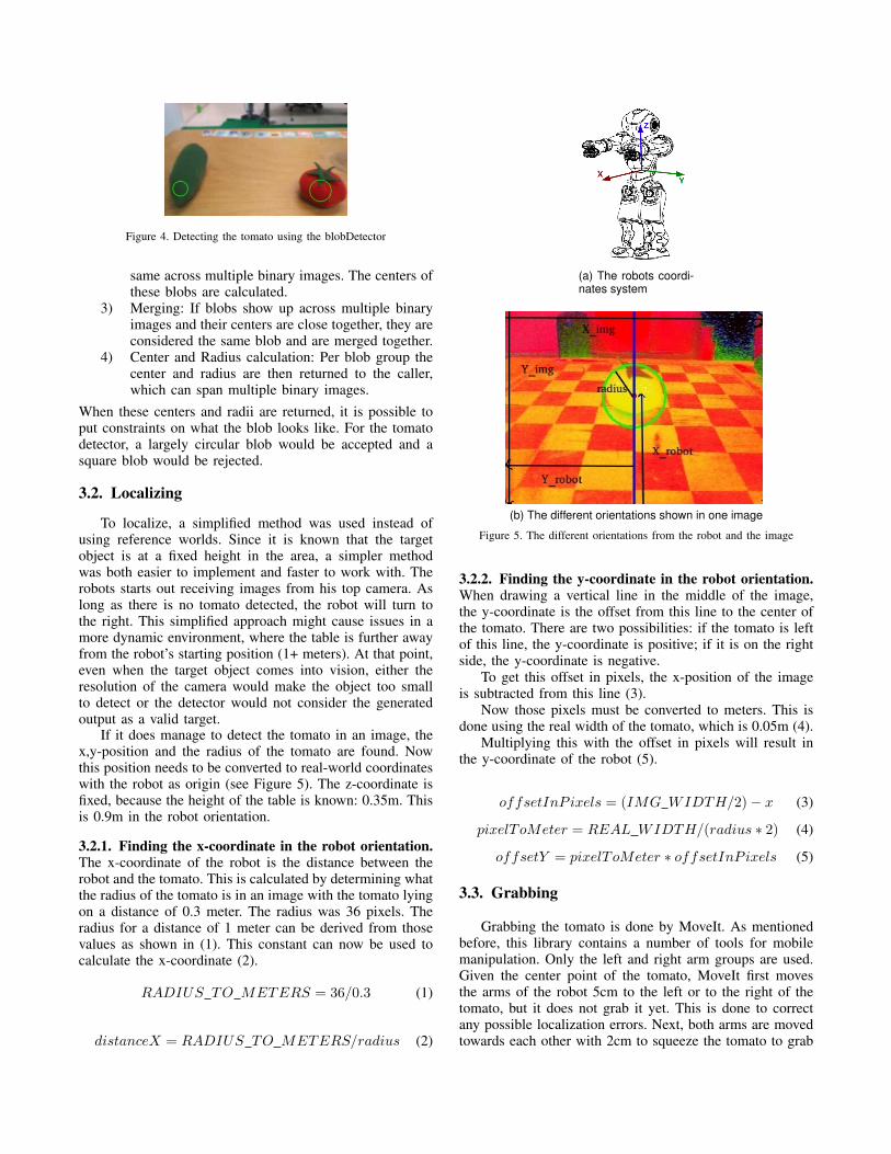
If it does manage to detect the tomato in an image, thex,y-position and the radius of the tomato are found. Nowthis position needs to be converted to real-world coordinateswith the robot as origin (see Figure 5). The z-coordinate isfixed, because the height of the table is known: 0.35m. Thisis 0.9m in the robot orientation.
3.2.1. Finding the x-coordinate in the robot orientation.The x-coordinate of the robot is the distance between therobot and the tomato. This is calculated by determining whatthe radius of the tomato is in an image with the tomato lyingon a distance of 0.3 meter. The radius was 36 pixels. Theradius for a distance of 1 meter can be derived from thosevalues as shown in (1). This constant can now be used tocalculate the x-coordinate (2).
RADIUS TO METERS = 36/0.3 (1)
distanceX = RADIUS TO METERS/radius (2)
(a) The robots coordi-nates system
(b) The different orientations shown in one image
Figure 5. The different orientations from the robot and the image
3.2.2. Finding the y-coordinate in the robot orientation.When drawing a vertical line in the middle of the image,the y-coordinate is the offset from this line to the center ofthe tomato. There are two possibilities: if the tomato is leftof this line, the y-coordinate is positive; if it is on the rightside, the y-coordinate is negative.
To get this offset in pixels, the x-position of the imageis subtracted from this line (3).
Now those pixels must be converted to meters. This isdone using the real width of the tomato, which is 0.05m (4).
Multiplying this with the offset in pixels will result inthe y-coordinate of the robot (5).
offsetInP ixels = (IMG WIDTH/2)− x (3)
pixelToMeter = REAL WIDTH/(radius ∗ 2) (4)
offsetY = pixelToMeter ∗ offsetInP ixels (5)
3.3. Grabbing
Grabbing the tomato is done by MoveIt. As mentionedbefore, this library contains a number of tools for mobilemanipulation. Only the left and right arm groups are used.Given the center point of the tomato, MoveIt first movesthe arms of the robot 5cm to the left or to the right of thetomato, but it does not grab it yet. This is done to correctany possible localization errors. Next, both arms are movedtowards each other with 2cm to squeeze the tomato to grab
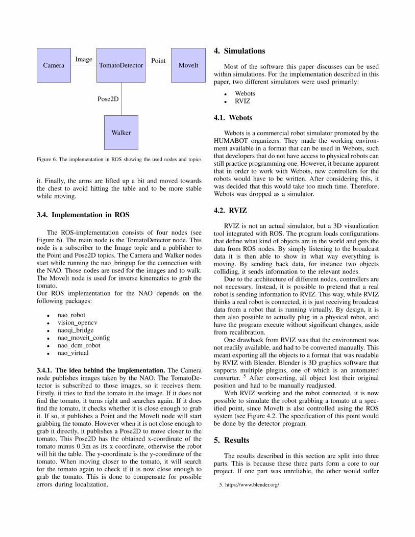
TomatoDetectorCamera MoveIt
Walker
Image Point
Pose2D
Figure 6. The implementation in ROS showing the used nodes and topics
it. Finally, the arms are lifted up a bit and moved towardsthe chest to avoid hitting the table and to be more stablewhile moving.
3.4. Implementation in ROS
The ROS-implementation consists of four nodes (seeFigure 6). The main node is the TomatoDetector node. Thisnode is a subscriber to the Image topic and a publisher tothe Point and Pose2D topics. The Camera and Walker nodesstart while running the nao bringup for the connection withthe NAO. Those nodes are used for the images and to walk.The MoveIt node is used for inverse kinematics to grab thetomato.Our ROS implementation for the NAO depends on thefollowing packages:
3.4.1. The idea behind the implementation. The Cameranode publishes images taken by the NAO. The TomatoDe-tector is subscribed to those images, so it receives them.Firstly, it tries to find the tomato in the image. If it does notfind the tomato, it turns right and searches again. If it doesfind the tomato, it checks whether it is close enough to grabit. If so, it publishes a Point and the MoveIt node will startgrabbing the tomato. However when it is not close enough tograb it directly, it publishes a Pose2D to move closer to thetomato. This Pose2D has the obtained x-coordinate of thetomato minus 0.3m as its x-coordinate, otherwise the robotwill hit the table. The y-coordinate is the y-coordinate of thetomato. When moving closer to the tomato, it will searchfor the tomato again to check if it is now close enough tograb the tomato. This is done to compensate for possibleerrors during localization.
4. Simulations
Most of the software this paper discusses can be usedwithin simulations. For the implementation described in thispaper, two different simulators were used primarily:
• Webots• RVIZ
4.1. Webots
Webots is a commercial robot simulator promoted by theHUMABOT organizers. They made the working environ-ment available in a format that can be used in Webots, suchthat developers that do not have access to physical robots canstill practice programming one. However, it became apparentthat in order to work with Webots, new controllers for therobots would have to be written. After considering this, itwas decided that this would take too much time. Therefore,Webots was dropped as a simulator.
4.2. RVIZ
RVIZ is not an actual simulator, but a 3D visualizationtool integrated with ROS. The program loads configurationsthat define what kind of objects are in the world and gets thedata from ROS nodes. By simply listening to the broadcastdata it is then able to show in what way everything ismoving. By sending back data, for instance two objectscolliding, it sends information to the relevant nodes.
Due to the architecture of different nodes, controllers arenot necessary. Instead, it is possible to pretend that a realrobot is sending information to RVIZ. This way, while RVIZthinks a real robot is connected, it is just receiving broadcastdata from a robot that is running virtually. By design, it isthen also possible to actually plug in a physical robot, andhave the program execute without significant changes, asidefrom recalibration.
One drawback from RVIZ was that the environment wasnot readily available, and had to be converted manually. Thismeant exporting all the objects to a format that was readableby RVIZ with Blender. Blender is 3D graphics software thatsupports multiple plugins, one of which is an automatedconverter. 5 After converting, all object lost their originalposition and had to be manually readjusted.
With RVIZ working and the robot connected, it is nowpossible to simulate the robot grabbing a tomato at a spec-ified point, since MoveIt is also controlled using the ROSsystem (see Figure 4.2. The specification of this point wouldbe done by the detector program.
5. Results
The results described in this section are split into threeparts. This is because these three parts form a core to ourproject. If one part was unreliable, the other would suffer
from it. Firstly, the tomato detectors are evaluated in section5.1. Then, with the best performing detector, the localizationalgorithm is evaluated in section 5.2 and section 5.3 will gointo detail about the results of grabbing the tomato. This isnot subjected to much theoretical testing, as it has to performwell in a physical setting. This means that we did not givethe task a measure on how well it was performed.
5.1. Tomato detector evaluation
The three detection algorithms are tested on ten differentimages: five images containing only one vegetable (tomato,carrot, cucumber, garlic or lettuce), three images containingall vegetables and two images containing all vegetableswithout the tomato. Table 1 shows the results of the differentdetection algorithms. “1” means that it detected the tomatoand “0” means that it did not detect anything. If somethingelse was detected, it will say what this was. As can beseen in this table, the color based method always detectsthe tomato and does not detect anything else. The circlebased approach does detect the tomato most of the time butit detects something in the background as a tomato once. Theblobs based method detects the tomato most of the time, butdetects a lot of other vegetables as the tomato as well. Thecolor based method is the best method and is used for therest of project.
5.2. Tomato localization evaluation
In order to create a sensible evaluation, a chessboard wasused to make sure the tomato was put in the same placeevery time. The squares on this chessboard are each of afixed length, making it very easy to create a discrete spaceon the surface. Table 2 shows the difference between the
TABLE 1. RESULTS OF THE DIFFERENT DETECTING ALGORITHMS1 MEANS DETECTED TOMATO, 0 MEANS DETECTED NOTHING
detected point and the actual point of the tomato. As can beseen in this table it does not work perfectly. However whenlooking at the differences, these are often not very large.Since there are ways to compensate those errors, they aredisregarded.
5.3. Tomato grabber evaluation
Getting MoveIt to run on a physical NAO proved moredifficult than anticipated. Even with the ROS interface beingable to easily swap between a simulation and a real NAO, theactuators that are controlled by MoveIt did not correspondto any on the physical NAO. This resulted in being unableto run a complete test including the tomato grabbing.
However, the simulation did show great results. Theanimation was able to grab the tomato after specifying thelocation the tomato detector thought it was at.
6. Discussion
After testing three different detectors, the one that per-formed best was picked, which was the color based andfinding contours detector. Since both the detector and thelocalization were interfaced with ROS, it was possible tocreate a rosbag. This rosbag contains information about thelocation the program thought the tomato was during tests.It is possible to play back the stored temporal informationby reading the file6.
Even thought the localization seemed to work within acertain error margin, future research might want to imple-ment a more sophisticated process. The simple approachworked because we optimized the algorithm to our environ-ment. When looking at the future, a new method is suggestedwhere the x distance from the robot is not calculated usingthe somewhat unreliable size, but for instance a positionderived from multiple viewpoints.
6. http://wiki.ros.org/rosbag
TABLE 2. RESULTS OF THE LOCALIZATION ALGORITHMS, IN METERS
Real x Real y Estimated x Estimated y Difference x Difference y
Multiple object recognition methods were explored inthis project and three were implemented and tested. Thecolor invariant detector does not work nearly as good as thecolor based detectors and thus was no longer considered.Using the best of the two left over detectors, the location ofthe tomato was estimated using pixel values. The locationwas fed to an inverse kinematics solver, which would thenbe able to grab the tomato and await further instructions.We view this as the first steps to a dynamic robot cook.
Acknowledgments
The authors would like to thank Arnoud Vissser.
References
[1] P. J. S. Enric Cervera, Juan Carlos Garcia, “Toward the robot butler:The humabot challenge,” Robotics & Automation Magazine, IEEE(Volume:22, Issue: 2), 2015.
[2] G. Ras, “Cognitive image processing for humanoid soccer in dynamicenvironments,” 2015.
[3] M. Quigley, K. Conley, B. P. Gerkey, J. Faust, T. Foote, J. Leibs,R. Wheeler, and A. Y. Ng, “Ros: an open-source robot operatingsystem,” in ICRA Workshop on Open Source Software, 2009.
[4] S. C. Sachin Chitta, Ioan Sucan, “Moveit!” Robotics & AutomationMagazine, IEEE (Volume:20, Issue: 1), 2012.
[5] G. Bradski, Dr. Dobb’s Journal of Software Tools.