This paper is a further step towards application of theModel-Based Systems Engineering (MBSE) paradigm,using standardized, graphical, and executable systemmodeling languages. It presents further development ofModelica graphical Modeling Language (Modeli-caML), a UML Profile for Modelica, which enables anintegrated modeling and simulation of system require-ments and design (for systems including both hardwareand software). This approach combines the power ofthe OMG UML/SysML standardized graphical notationfor system and software modeling, and the modelingand simulation power of Modelica. It facilitates thecreation of executable system-specification and analy-sis models that can simulate time-discrete (or event-based) and time-continuous system behavior.Keywords: Modelica, ModelicaML, UML, SysML,graphical modeling, system requirements, system de-sign.
1 Introduction
UML/SysML [2],[4] and Modelica [1] are object-oriented modeling languages. Both provide means torepresent a system as objects and to describe its internalstructure and behavior. SysML is a UML profile forsystems modeling. It facilitates efficient capturing ofrelevant system requirements, design, or test data bymeans of graphical formalisms, crosscutting constructsand views (diagrams) on the model-data. Modelica isdefined as a textual language with standardized graphi-cal annotations for model icons, and is designed forefficient simulation of system dynamic behavior.
1.1 Paper Structure
This paper first presents the motivation and previouswork done on the integration of UML/SysML andModelica, followed by a brief description of
UML/SysML, Modelica, and ModelicaML languages.Section 4 summarizes the basic mapping between UMLand Modelica, which results in the ModelicaML pro-file, and provides examples of applications. Section 5discusses graphical notations for Modelica behavioralconcepts. Sections 6 and 7 discuss ModelicaML con-cepts not present in Modelica. Sections 8, 9 and 10 ad-dress the supporting modeling, code generation andsimulation environment.
2 Motivation
By integrating Modelica and UML/SysML theUML/SysML's strength in graphical and descriptivemodeling is complemented with Modelica's formal ex-ecutable modeling for analyses and trade studies. Viceversa, Modelica will benefit from using the selectedsubset of the UML/SysML graphical notation (visualformalisms) for editing, reading and maintainingModelica models.
Graphical modeling, as promoted by the OMG [13],promises to be more effective and efficient, regardingediting, human reader perception of models, and main-taining models compared to a traditional textual repre-sentation. A unified, standardized graphical notation forsystems modeling and simulation will facilitate thecommon understanding of models for parties involvedin the development of systems (i.e., system-engineers,designers, and testers; software-developers, customersor stakeholder).
Existing UML/SysML formalisms are typicallytranslated into (and limited to) the time-discrete orevent-based simulation of a system or software. Thislimitation disappears when Modelica comes into play.UML/SysML models will then be of a higher expres-siveness and correctness, because they will becomeexecutable while covering simulation of hardware andsoftware, with integrated continuous-time and event-based or time-discrete behavior.
Some research work previously done has already iden-tified the need for integrating UML/SysML and Mode-lica, and has addressed integration issues to some ex-tent. For example, [7] has identified the basic mappingof the structural constructs of Modelica to SysML. Italso pointed out that the SysML Parametrics concept isnot sufficient for modeling the equation-based behaviorof a class. By contrast, [9] leverages the SysML Pa-rametrics concept for the integration of continuous-timebehavior into SysML models. [8] presents a concept touse SysML for integrating models of continuous-timedynamic system behavior with SysML informationmodels representing systems engineering problems, andprovides rules for graph-based bidirectional transforma-tion of SysML and Modelica models.
The main focus of this paper is the representation ofModelica behavioral constructs using graphical nota-tions and formalisms that are based on a subset ofUML, which can be translated into executable Mode-lica code.
3.1 OMG Systems Modeling Language(SysML)
SysML [4] is a UML profile1 and a general-purposesystems modeling language that enables systems engi-neers to create and manage models of engineered sys-tems using graphical notations. SysML reuses a subsetof UML 2.1 [2] constructs and extends them by addingnew modeling elements and two new diagram types.Through these extensions, SysML is capable of repre-senting the specification, analysis, design, verification,and validation of any engineered system.
MBSE promotes the usage of models as primaryengineering artifacts. However, textual requirementsare still the main vehicle for communicating and agree-ing on system specification in a system developmentprocess. SysML provides mechanisms to include tex-tual requirements into models. In doing so, traceabilityof textual requirements to design artifacts and test casesis facilitated.
The logical behavior of systems is captured inSysML through a combination of activity diagrams,state machine diagrams, and/or interaction diagrams. Inaddition, SysML includes Parametrics to support theexecution of constraint-based behavior such as con-tinuous-time dynamics in terms of energy flow. How-ever, the syntax and semantics of such behavioral de-scriptions in Parametrics have been left unspecified to
1 UML profiles allow domain-specific extensions of UMLby means of stereotypes.
interoperate with other simulation and analysis model-ing capabilities.
3.2 The Modelica Language
Modelica is an object-oriented equation-based model-ing language primarily aimed at physical systems. Themodel behavior is based on ordinary and differentialalgebraic equation (OAE and DAE) systems combinedwith discrete events, so-called hybrid DAEs. Suchmodels are ideally suited for representing physical be-havior and the exchange of energy, signals, or othercontinuous-time or discrete-time interactions betweensystem components.
Modelica models are similar in structure toUML/SysML models in the sense that Modelica mod-els consist of compositions of sub-models connected byports that represent energy flow (undirected) or signalflow (directed). The models are acausal, equation-based, and declarative. The Modelica language is de-fined and maintained by the Modelica Association [1]which publishes a formal specification but also pro-vides an extensive Modelica Standard Library that in-cludes a broad foundation of essential models coveringdomains ranging from (analog and digital) electricalsystems, mechanical motion and thermal systems, toblock diagrams for control. Finally, it is worth notingthat there are several efforts within the Modelica com-munity to develop open-source solvers, such as in theOpenModelica project [12].
3.3 ModelicaMLThis paper presents the further development of the
Modelica graphical Modeling Language (Modeli-caML), a UML profile for Modelica. The main purposeof ModelicaML is to enable an efficient and effectiveway to create, read or understand, and maintain Mode-lica models reusing notations that are also used forsoftware modeling. ModelicaML is defined as agraphical notation that facilitates different views (com-position, inheritance, behavior) on system models. It isbased on a subset of the OMG Unified Modeling Lan-guage (UML) and reuses concepts from the OMG Sys-tems Modeling Language (SysML). ModelicaML isdesigned towards the generation of Modelica code fromgraphical models. Since the ModelicaML profile is anextension of the UML meta-model it can be used forboth: Modeling with standard UML and with SysML2.
UML/SysML provide the modeler with powerfuldescriptive constructs at the expense of loosely defined
2 SysML itself is also a UML Profile. All stereotypes thatextend UML meta-classes are also applicable to the corre-sponding SysML elements.
semantics that are marked as “semantic variationpoints” in the UML/SysML specifications. The inten-tion of ModelicaML is to provide the modeler withpowerful executable constructs and precise executionsemantics that are based on the Modelica language.
Therefore, ModelicaML uses a limited set of theUML, extends the UML meta-model (using the UMLprofiling mechanism) with new constructs in order tointroduce missing Modelica concepts, and reuses con-cepts from the SysML. However, like UML andSysML, ModelicaML is only a graphical notation.ModelicaML models are eventually translated intoModelica code. Hence, the execution semantics aredefined by the Modelica language and ultimately by aModelica compiler that will translate the generatedModelica code into an executable form.
4 Representing Modelica StructuralConstructs in ModelicaML
The class concept is the basic structural unit in Mode-lica. Classes provide the structure for objects and con-tain equations, which ultimately serves as the basis forthe executable simulation code. The most general kindof class is “model”. Specialized categories of classessuch as “record”, “type”, “block”, “package”, “func-tion” and “connector” have most of the properties of a“model” but with restrictions and sometimes enhance-ments.
In UML the “Class” is the main structural unitwhich can have behavior. A non-behavioral concept isthe “DataType”.
The following table summarizes the mapping of thestructural Modelica constructs to UML. The details ofthe associated properties of the Modelica constructs areleft out.
Table 1: Mapping of Modelica structural constructs toUML
Modelica UML
package UML::Package
model, block UML::Class
connector, record, type UML::DataType
component of type connector UML::Port
variable, component UML::Property
extends relation UML::Generalization
connection clause UML::Connector
The mapping listed above is specified by [11] andhas been implemented as a UML profile in a the E-clipse-based open-source tool Papyrus UML [10].Modelica constructs are represented using stereotypes
(extensions of the UML meta-model) with requiredproperties (attributes) that are specific to Modelica.
It is subject to the current implementation work ofthe ModelicaML editor to reflect the Modelica lan-guage wording, so that the Modelica modeler will notbe forced to work with UML/SysML wording. Basedon this mapping it is also possible to import existingModelica models (or libraries) into ModelicaML mod-els, to represent them using graphical notations and toreuse them the same way as is done in Modelica tools.
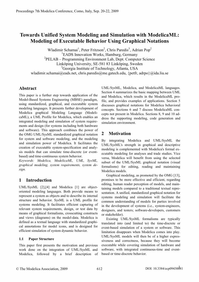
The following figures present examples of tank sys-tems inspired from [3], sections 12.2.3, 12.2.4 and12.2.5. The only means to represent Modelica codegraphically is the Modelica connection diagram (seethe two tanks example on the Figure 1). A ConnectionDiagram shows Modelica class components (typicallydepicted as domain specific icons with connectors) ofthe class and their interconnection (connect clauses) asdepicted in the figure below. The graphical notation isdefined by the Modelica modeler (e.g. the developer ofa library) and is not standardized by the language speci-fication; it is usually specific to the domain of applica-tion.
Figure 1. Two Tanks System example, [3] page 391.
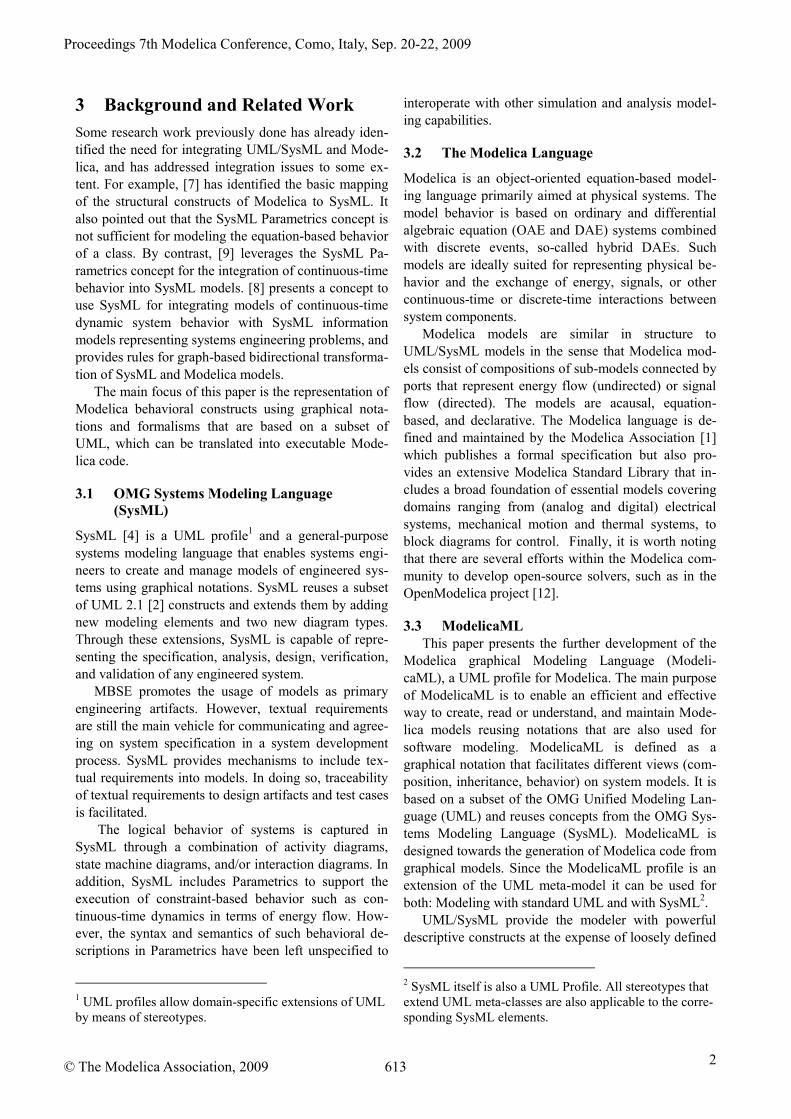
The corresponding ModelicaML notation is basedon the UML Composite Diagram as illustrated inFigure 2.
Figure 2. Example of ModelicaML notation(connections)
By contrast, UML defines different types of dia-grams, which enable different visual views on themodel data, such as inheritance, classes that are nested,the composition of a class or interconnection of com-ponents of a class or its defined behavior.
Moreover, the graphical notation is not specific to adomain (although it is possible to include domain spe-cific icons into the class compartment). It is abstracted
from the domain. Thanks to such an abstracted, unifiednotation, engineers from different domains or disci-plines will share a common understanding of themodel.
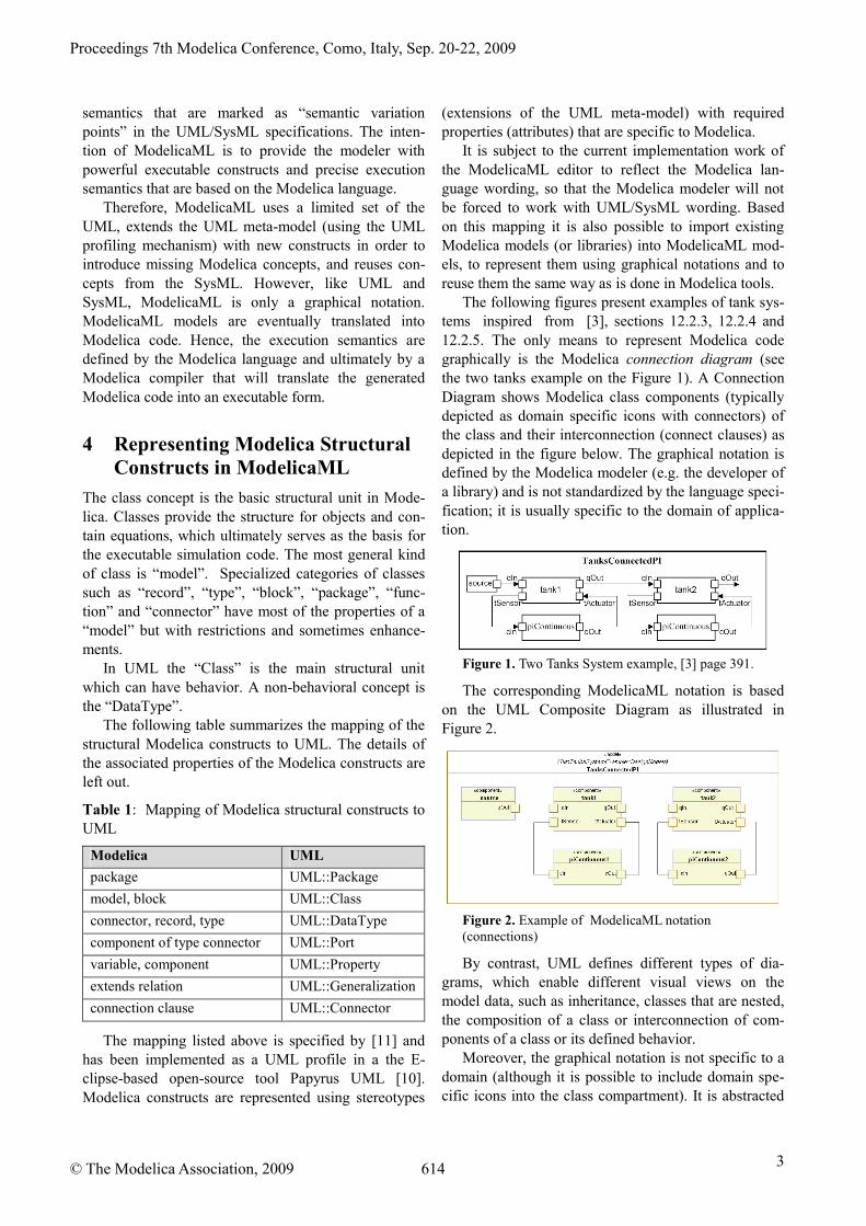
Figure 3. Example of ModelicaML notation (packages,classes)
Figure 4. Example of ModelicaML notation (class,components, asserts)
Figure 5. Example of ModelicaML notation(inheritance)
In particular the inheritance (extension) graphical rep-resentation (Figure 5) is useful if there are multiple lev-els of inheritance.
5 Representing Modelica BehavioralConstructs in ModelicaML
Modelica does not define any graphical notation forrepresenting the behavior of a class. Instead, the behav-ior of a Modelica Class is specified by its equations oralgorithm statements (including all conditional con-structs) which are provided as text.
In addition to basic equations or statements Mode-lica defines conditional constructs, which are allowedin both equation and algorithm sections, and can havenested constructs or not.
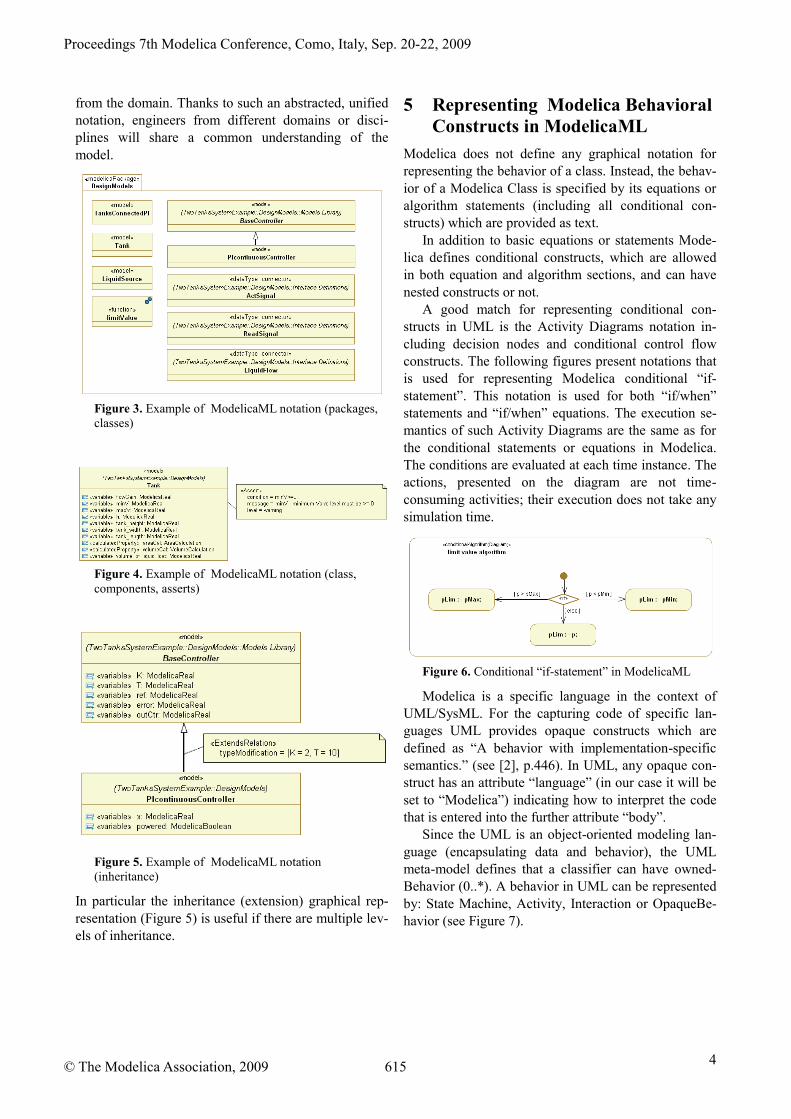
A good match for representing conditional con-structs in UML is the Activity Diagrams notation in-cluding decision nodes and conditional control flowconstructs. The following figures present notations thatis used for representing Modelica conditional “if-statement”. This notation is used for both “if/when”statements and “if/when” equations. The execution se-mantics of such Activity Diagrams are the same as forthe conditional statements or equations in Modelica.The conditions are evaluated at each time instance. Theactions, presented on the diagram are not time-consuming activities; their execution does not take anysimulation time.
Figure 6. Conditional “if-statement” in ModelicaML
Modelica is a specific language in the context ofUML/SysML. For the capturing code of specific lan-guages UML provides opaque constructs which aredefined as “A behavior with implementation-specificsemantics.” (see [2], p.446). In UML, any opaque con-struct has an attribute “language” (in our case it will beset to “Modelica”) indicating how to interpret the codethat is entered into the further attribute “body”.
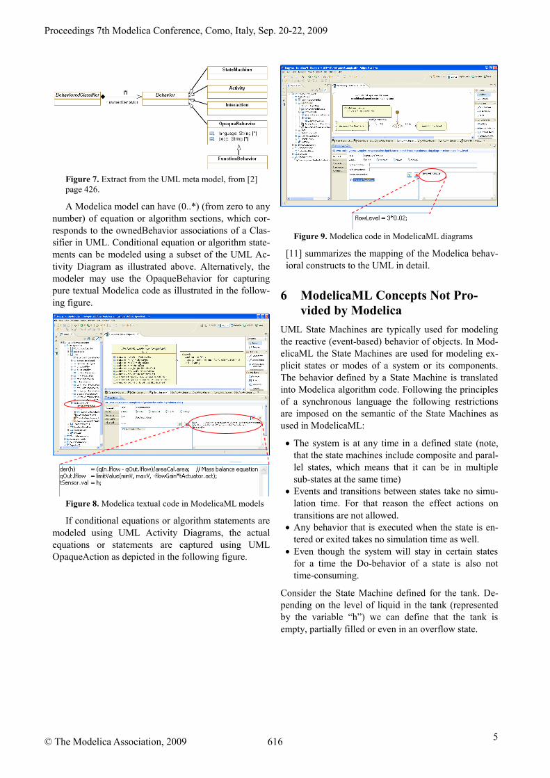
Since the UML is an object-oriented modeling lan-guage (encapsulating data and behavior), the UMLmeta-model defines that a classifier can have owned-Behavior (0..*). A behavior in UML can be representedby: State Machine, Activity, Interaction or OpaqueBe-havior (see Figure 7).
Figure 7. Extract from the UML meta model, from [2]page 426.
A Modelica model can have (0..*) (from zero to anynumber) of equation or algorithm sections, which cor-responds to the ownedBehavior associations of a Clas-sifier in UML. Conditional equation or algorithm state-ments can be modeled using a subset of the UML Ac-tivity Diagram as illustrated above. Alternatively, themodeler may use the OpaqueBehavior for capturingpure textual Modelica code as illustrated in the follow-ing figure.
Figure 8. Modelica textual code in ModelicaML models
If conditional equations or algorithm statements aremodeled using UML Activity Diagrams, the actualequations or statements are captured using UMLOpaqueAction as depicted in the following figure.
Figure 9. Modelica code in ModelicaML diagrams
[11] summarizes the mapping of the Modelica behav-ioral constructs to the UML in detail.
6 ModelicaML Concepts Not Pro-vided by Modelica
UML State Machines are typically used for modelingthe reactive (event-based) behavior of objects. In Mod-elicaML the State Machines are used for modeling ex-plicit states or modes of a system or its components.The behavior defined by a State Machine is translatedinto Modelica algorithm code. Following the principlesof a synchronous language the following restrictionsare imposed on the semantic of the State Machines asused in ModelicaML:
The system is at any time in a defined state (note,that the state machines include composite and paral-lel states, which means that it can be in multiplesub-states at the same time)
Events and transitions between states take no simu-lation time. For that reason the effect actions ontransitions are not allowed.
Any behavior that is executed when the state is en-tered or exited takes no simulation time as well.
Even though the system will stay in certain statesfor a time the Do-behavior of a state is also nottime-consuming.
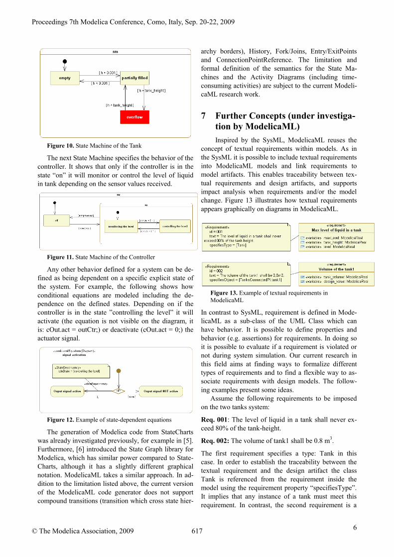
Consider the State Machine defined for the tank. De-pending on the level of liquid in the tank (representedby the variable “h”) we can define that the tank isempty, partially filled or even in an overflow state.
The next State Machine specifies the behavior of thecontroller. It shows that only if the controller is in thestate “on” it will monitor or control the level of liquidin tank depending on the sensor values received.
Figure 11. State Machine of the Controller
Any other behavior defined for a system can be de-fined as being dependent on a specific explicit state ofthe system. For example, the following shows howconditional equations are modeled including the de-pendence on the defined states. Depending on if thecontroller is in the state ”controlling the level” it willactivate (the equation is not visible on the diagram, itis: cOut.act = outCtr;) or deactivate (cOut.act = 0;) theactuator signal.
Figure 12. Example of state-dependent equations
The generation of Modelica code from StateChartswas already investigated previously, for example in [5].Furthermore, [6] introduced the State Graph library forModelica, which has similar power compared to State-Charts, although it has a slightly different graphicalnotation. ModelicaML takes a similar approach. In ad-dition to the limitation listed above, the current versionof the ModelicaML code generator does not supportcompound transitions (transition which cross state hier-
archy borders), History, Fork/Joins, Entry/ExitPointsand ConnectionPointReference. The limitation andformal definition of the semantics for the State Ma-chines and the Activity Diagrams (including time-consuming activities) are subject to the current Modeli-caML research work.
7 Further Concepts (under investiga-tion by ModelicaML)
Inspired by the SysML, ModelicaML reuses theconcept of textual requirements within models. As inthe SysML it is possible to include textual requirementsinto ModelicaML models and link requirements tomodel artifacts. This enables traceability between tex-tual requirements and design artifacts, and supportsimpact analysis when requirements and/or the modelchange. Figure 13 illustrates how textual requirementsappears graphically on diagrams in ModelicaML.
Figure 13. Example of textual requirements inModelicaML
In contrast to SysML, requirement is defined in Mode-licaML as a sub-class of the UML Class which canhave behavior. It is possible to define properties andbehavior (e.g. assertions) for requirements. In doing soit is possible to evaluate if a requirement is violated ornot during system simulation. Our current research inthis field aims at finding ways to formalize differenttypes of requirements and to find a flexible way to as-sociate requirements with design models. The follow-ing examples present some ideas.
Assume the following requirements to be imposedon the two tanks system:
Req. 001: The level of liquid in a tank shall never ex-ceed 80% of the tank-height.
Req. 002: The volume of tank1 shall be 0.8 m3.
The first requirement specifies a type: Tank in thiscase. In order to establish the traceability between thetextual requirement and the design artifact the classTank is referenced from the requirement inside themodel using the requirement property “specifiesType”.It implies that any instance of a tank must meet thisrequirement. In contrast, the second requirement is a
design requirement defining the required volume oftank 1. This requirement is imposed only on a particu-lar instance of the type Tank. Therefore, the dot-notation in the requirement property “specifiesObject”is used to reference the respective instance. The “speci-fies…” - relations are descriptive only. They are nottranslated into Modelica code and do not impact thesimulation.
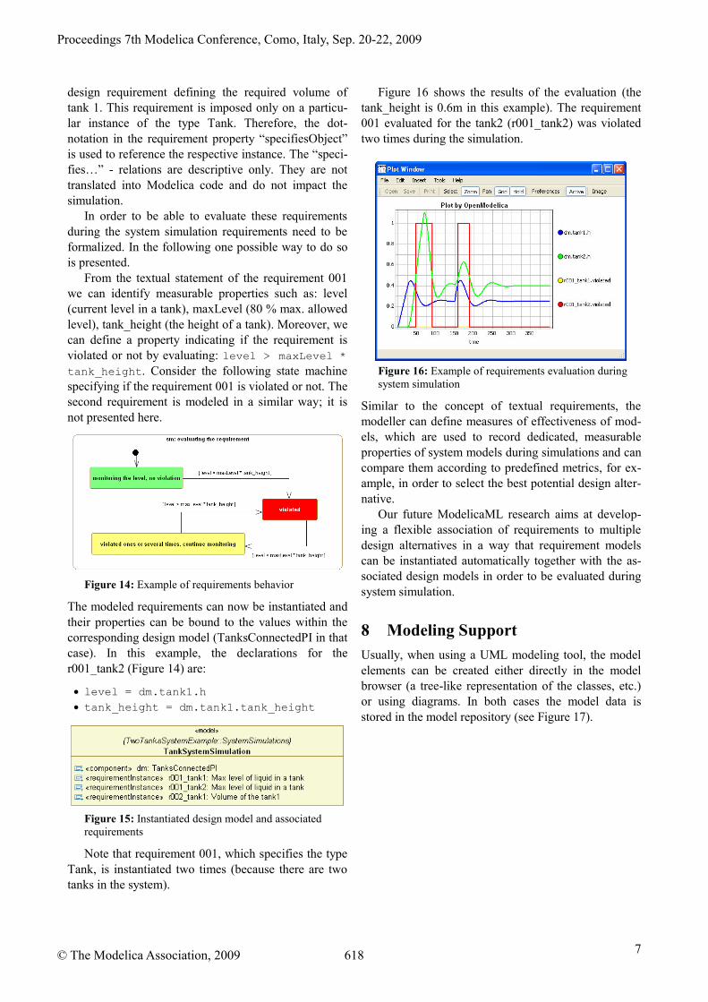
In order to be able to evaluate these requirementsduring the system simulation requirements need to beformalized. In the following one possible way to do sois presented.
From the textual statement of the requirement 001we can identify measurable properties such as: level(current level in a tank), maxLevel (80 % max. allowedlevel), tank_height (the height of a tank). Moreover, wecan define a property indicating if the requirement isviolated or not by evaluating: level > maxLevel *
tank_height. Consider the following state machinespecifying if the requirement 001 is violated or not. Thesecond requirement is modeled in a similar way; it isnot presented here.
Figure 14: Example of requirements behavior
The modeled requirements can now be instantiated andtheir properties can be bound to the values within thecorresponding design model (TanksConnectedPI in thatcase). In this example, the declarations for ther001_tank2 (Figure 14) are:
level = dm.tank1.h
tank_height = dm.tank1.tank_height
Figure 15: Instantiated design model and associatedrequirements
Note that requirement 001, which specifies the typeTank, is instantiated two times (because there are twotanks in the system).
Figure 16 shows the results of the evaluation (thetank_height is 0.6m in this example). The requirement001 evaluated for the tank2 (r001_tank2) was violatedtwo times during the simulation.
Figure 16: Example of requirements evaluation duringsystem simulation
Similar to the concept of textual requirements, themodeller can define measures of effectiveness of mod-els, which are used to record dedicated, measurableproperties of system models during simulations and cancompare them according to predefined metrics, for ex-ample, in order to select the best potential design alter-native.
Our future ModelicaML research aims at develop-ing a flexible association of requirements to multipledesign alternatives in a way that requirement modelscan be instantiated automatically together with the as-sociated design models in order to be evaluated duringsystem simulation.
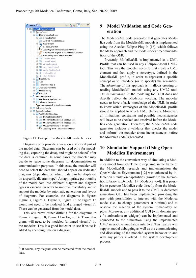
8 Modeling Support
Usually, when using a UML modeling tool, the modelelements can be created either directly in the modelbrowser (a tree-like representation of the classes, etc.)or using diagrams. In both cases the model data isstored in the model repository (see Figure 17).
Diagrams only provide a view on a selected part ofthe model data. Diagrams can be used only for model-ing (i.e., capturing the data), and might be deleted3 afterthe data is captured. In some cases the modeler maydecide to leave some diagrams for documentation orcommunication purposes. In this case, the modeler willneed to select the data that should appear on dedicateddiagrams (depending on which data can be displayedon a specific diagram type). An appropriate partitioningof the model data into different diagram and diagramtypes is essential in order to improve readability and tosupport the modeler by automatic generation and layoutof diagrams. For example, the diagrams in figuresFigure 3, Figure 4, Figure 5, Figure 13 or Figure 15would not need to be modeled (and arranged visually).These can be generated from the model data.
This will prove rather difficult for the diagrams inFigure 2, Figure 10, Figure 11 or Figure 14. Those dia-grams will need to be modeled (arranged visually) bythe modeler. This is a good indicator to see if value isadded by spending time on a diagram.
3 Of course, any diagram can be recreated from the modeldata.
9 Model Validation and Code Gen-eration
The ModelicaML code generator that generates Mode-lica code from the ModelicaML models is implementedusing the Acceleo Eclipse Plug-In [16], which followsthe MDA approach and the model-to-text recommenda-tions of the OMG.
Presently, ModelicaML is implemented as a UMLProfile that can be used in any (Eclipse-based) UML2tool. This way the modeler needs to first create a UMLelement and then apply a stereotype, defined in theModelicaML profile, in order to represent a specificconcept or to introduce (or to specify) the semantics.The advantage of this approach is: it allows creating orreading ModelicaML models using any UML2 tool.The disadvantage is: the modeling tool GUI does notdirectly reflect the Modelica wording. The modelerneeds to have a basic knowledge of the UML in orderto know which stereotypes of the ModelicaML profileshould be applied to which UML elements. Moreover,all limitations, constraints and possible inconsistencieswill have to be checked and resolved before the Mode-lica code generation. Therefore, the ModelicaML codegenerator includes a validator that checks the modeland informs the modeler about inconsistencies beforethe Modelica code is generated.
10 Simulation Support (Using Open-Modelica Environment)
In addition to the convenient way of simulating a Mod-elica model from startTime to stopTime, in the frame ofthe ModelicaML research and implementation theOpenModelica Environment [12] was enhanced by in-teraction simulation capabilities (similar to the Interac-tion Library in Dymola [15] Modelica tool). It is possi-ble to generate Modelica code directly from the Mode-licaML models and to pass it to the OMC. A dedicatedsimulation GUI has been implemented providing theuser with possibilities to interact with the Modelicamodel (i.e., to change parameters at runtime) and toobserve the reaction of the system immediately onplots. Moreover, any additional GUI (with domain spe-cific animations or widgets) can be implemented andconnected to the simulation using the implementedOMC interactive simulation interface. This feature willsupport model debugging as well as the communicatingand discussing of the modeled system behavior to andwith any parties involved in the system developmentprocess.
This paper presents a step towards, and a proof of con-cept for, a unified executable system modeling lan-guage and environment using open-source UML mod-eling (Papyrus UML) and simulation (OpenModelica)tools.
One of our main future research activities in thefield of ModelicaML will be dedicated to developinggraphical notations for modeling any kind of equationsor statements, as well as other constructs (e.g. type- orinstance-modification) that are now captured usingstrings. This will avoid the refactoring of models andenable semantic analysis of the ModelicaML models.
In conclusion, UML/SysML and Modelica are com-plementary languages supported by two active commu-nities. By integrating UML/SysML and Modelica intoModelicaML, we combine the very expressive, formallanguage for differential algebraic equations and dis-crete events of Modelica with the expressiveUML/SysML graphical notation for requirements,structural decomposition, logical behavior, and corre-sponding cross-cutting constructs.
In addition, the two communities are expected tobenefit from the exchange of multi-domain model li-braries and the potential for improved and expandedcommercial and open-source tool support.
12 Acknowledgements
This work has been supported by EADS InnovationWorks, by Swedish Vinnova in the ITEA2 OPEN-PROD project and by the Swedish Research Council(VR).
References
[1] Modelica Association. Modelica: A Unified Ob-ject-Oriented Language for Physical SystemsModeling: Language Specification Version 3.0,Sept 2007. www.modelica.org
[2] OMG. OMG Unified Modeling Language TM
(OMG UML). Superstructure Version 2.2, Feb-ruary 2009.
[3] Fritzson P. Principles of Object-Oriented Model-ing and Simulation with Modelica 2.1. Wiley-IEEE Press, 2004.
[4] OMG. OMG Systems Modeling Language(OMG SysML™), Version 1.1, November 2008.
[5] Ferreira J. A. and Estima de Oliveira J. P., De-partment of Mechanical Engineering, Universityof Aveiro, 3810 Aveiro (PORTUGAL), Depart-ment of Electronic Engineering, University of
Aveiro, 3810 Aveiro (PORTUGAL), MODEL-LING HYBRID SYSTEMS USING STATE-CHARTS AND MODELICA, J. A.
[6] M. Otter, K.-E. Arz´en, I. Dressler. StateGraph-AModelica Library for Hierarchical State Ma-chines. DLR Oberpfaenhofen, Germany; LundInstitute of Technology, Sweden. Proceedings ofthe 4th International Modelica Conference, Ham-burg. March 7-8, 200.
[7] Pop, A., and Akhvlediani, D., and Fritzson, P.Towards Unified Systems Modeling with theModelicaML UML Profile. International Work-shop on Equation-Based Object-Oriented Lan-guages and Tools. Berlin, Germany, LinköpingUniversity Electronic Press, 2007
[8] Peak, R., McGinnis, L., Paredis, C. IntegratingSystem Design with Simulation and Analysis Us-ing SysML – Phase 1 Final Report. 2008
[9] Johnson, T. A. Integrating Models and Simula-tions of Continuous Dynamic System Behaviorinto SysML. M.S. Thesis, G.W. Wood-ruffSchool of Mechanical Engineering, Georgia In-stitute of Technology. Atlanta, GA. 2008
[10] Papyrus UML, www.papyrusuml.org
[11] Schamai W.. Modelica Modeling Language(ModelicaML) A UML Profile for Modelica,technical report 2009:5, EADS IW, Germany,Linkoping University, Sweden, 2009
[12] The OpenModelica Projectwww.ida.liu.se/labs/pelab/modelica/OpenModelica.html
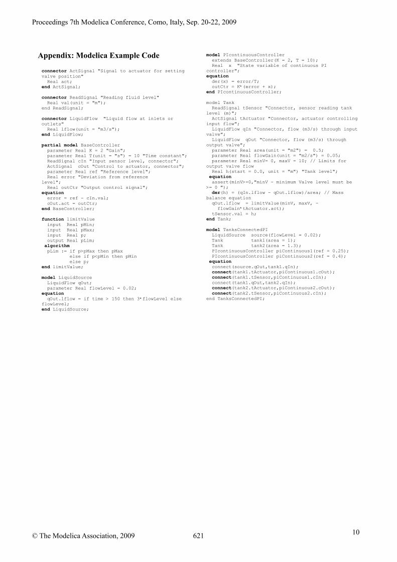
connector LiquidFlow "Liquid flow at inlets oroutlets"
Real lflow(unit = "m3/s");end LiquidFlow;
partial model BaseControllerparameter Real K = 2 "Gain";parameter Real T(unit = "s") = 10 "Time constant";ReadSignal cIn "Input sensor level, connector";ActSignal cOut "Control to actuator, connector";parameter Real ref "Reference level";Real error "Deviation from reference
level";Real outCtr "Output control signal";
equationerror = ref - cIn.val;cOut.act = outCtr;
end BaseController;
function limitValueinput Real pMin;input Real pMax;input Real p;output Real pLim;
algorithmpLim := if p>pMax then pMax
else if p<pMin then pMinelse p;
end limitValue;
model LiquidSourceLiquidFlow qOut;parameter Real flowLevel = 0.02;
equationqOut.lflow = if time > 150 then 3*flowLevel else
flowLevel;end LiquidSource;
model PIcontinuousControllerextends BaseController(K = 2, T = 10);Real x "State variable of continuous PI
controller";equation
der(x) = error/T;outCtr = K*(error + x);
end PIcontinuousController;
model TankReadSignal tSensor "Connector, sensor reading tank