INCH VERSION The TOX ® -Powerpackage is available with different press forces, strokes and structural shapes. Selection criteria: 1) Press force required for the application 2) Available air pressure 3) Required total stroke of the TOX ® -Powerpackage 4) Required power stroke of the TOX ® -Powerpackage 5) Type of application as e.g. punching, embossing etc. 6) Available installation space Description for ordering the TOX ® -Powerpackage S 4.30.50.6 US inch execution (blank for metric cylinders) power stroke (mm) total stroke (mm) TOX ® -Powerpackage version (145 psi/90 psi) press force category (kN) series type Type S 90/145 psi Version .50 with power stroke adjustment Type K 90/145 psi Version .51 with total stroke adjustment Type T Type RP Type KT, see TOX ® Pneumo-Hydraulic Intensifier System leaflet. Accessories/special version see page 2 – 10 see page 11 – 15 see page 16 – 17 see page 18 – 35 A series overview up to 195 tons press force up to 188 psi press force up to 11.81 inch total stroke up to 15.75 inch total stroke up to .79 inch power stroke up to 3.15 inch power stroke Patented power bypass with integrated retract hydraulic cushion is a standard feature for all TOX ® -Powerpackages type S4 to S170. For further executions see our data sheets 10.06 and 10.08. Type S (standard) 30 psi – 90 psi bar series 30 psi – 145 psi series Type K (compact) and version K 51 with total stroke adjustment 30 psi – 90 psi series 30 psi – 145 psi series Type KT flexible solution for small mounting dimensions, long power strokes 30 psi – 90 psi series 30 psi – 145 psi series Type T, the turbo cylinder: up to Type RP embossing cylinder 550 strokes/min, only power stroke with anti-rotation lock 40 psi – 145 psi series type T 40 psi – 145 psi series type RP up to 180 tons press force up to 192 tons press force up to 7.87 inch total stroke up to 15.75 inch total stroke up to .39 inch power stroke up to 1.95 inch power stroke Patented power bypass with integrated retract hydraulic cushion is available on request. For further executions see our data sheet 10.06. up to 13.5 tons press force up to 17.8 tons press force up to .47 inch total stroke up to 1.25 inch total stroke up to .47 inch power stroke up to .12 inch power stroke up to 200 tons press force up to 200 tons press force up to 15.75 inch total stroke up to 15.75 inch total stroke up to 15.75 inch power stroke up to 15.75 inch power stroke Accessories/specials Mounting instructions / tables / notes The TOX ® -Powerpackage welding cylinder Please ask for our information material. TOX ® PRESSOTECHNIK L.L.C. • 4250 Weaver Parkway • Warrenville, IL 60555 USA • Tel. (630) 447-4600 Fax (630) 393-6800 • E-Mail: [email protected]• www.tox-us.com TOX ® -Powerpackage: The complete drive family for press forces from .2 to 200 tons Data sheet 10.00 2012/01
Transcript
INCH VERSION
The TOX®-Powerpackage is available with different press forces, strokes and structural shapes.
Selection criteria:1) Press force required for the application2) Available air pressure3) Required total stroke of the TOX®-Powerpackage4) Required power stroke of the TOX®-Powerpackage5) Type of application as e.g. punching, embossing etc.6) Available installation space
Description for ordering theTOX®-PowerpackageS 4.30.50.6 US
inch execution (blank for metric cylinders)power stroke (mm)
total stroke (mm)TOX®-Powerpackage version(145 psi/90 psi)press force category (kN)series type
Type S 90/145 psi
Version .50 with power stroke adjustment
Type K 90/145 psi
Version .51 with total stroke adjustment
Type T
Type RP
Type KT, see TOX® Pneumo-HydraulicIntensifier System leaflet.
Accessories/special version
see page 2 – 10
see page 11 – 15
see page 16 – 17
see page 18 – 35
A series overview
up to 195 tons press force up to 188 psi press forceup to 11.81 inch total stroke up to 15.75 inch total strokeup to .79 inch power stroke up to 3.15 inch power stroke
Patented power bypass with integrated retract hydraulic cushionis a standard feature for all TOX®-Powerpackages type S4 to S170.
For further executions see our data sheets 10.06 and 10.08.
Type S (standard)30 psi – 90 psi bar series 30 psi – 145 psi series
Type K (compact) and version K 51 with total stroke adjustment30 psi – 90 psi series 30 psi – 145 psi series
Type KT flexible solution for small mounting dimensions,long power strokes30 psi – 90 psi series 30 psi – 145 psi series
Type T, the turbo cylinder: up to Type RP embossing cylinder 550 strokes/min, only power stroke with anti-rotation lock40 psi – 145 psi series type T 40 psi – 145 psi series type RP
up to 180 tons press force up to 192 tons press forceup to 7.87 inch total stroke up to 15.75 inch total strokeup to .39 inch power stroke up to 1.95 inch power stroke
Patented power bypass with integrated retracthydraulic cushion is available on request.
For further executions see our data sheet 10.06.
up to 13.5 tons press force up to 17.8 tons press forceup to .47 inch total stroke up to 1.25 inch total stroke up to .47 inch power stroke up to .12 inch power stroke
up to 200 tons press force up to 200 tons press forceup to 15.75 inch total stroke up to 15.75 inch total strokeup to 15.75 inch power stroke up to 15.75 inch power stroke
Accessories/specials
Mounting instructions / tables / notes
The TOX®-Powerpackage welding cylinderPlease ask for our information material.
TOX®-Powerpackage:The complete drive family for press forces from .2 to 200 tons
Datasheet10.00
2012/01
2 www.tox-us.com TB 10.00_201201.us
17 4
O
A
N
C
D
S 2 - S 15
5632
B
G
KM
W
LØ H
Ø F
ØV
S
E E
R
Rückhub EilhubReturn stroke
E
Fast approach stroke
1 Control throttle X2 High-pressure measuring hose3 Oil filling nipple4 Change over valve fast approach stroke/power stroke5 Bleed plate6 Oil level indicator7 Bleed screw8 Pneumatic spring (LF)9 Pneumatic spring connection (permanent pressure)
R
483 5 9217 6
S
E
M K
G
B U
W E
ØF
ØV
ØH L
D
S 75/100
C
AO
N
D
S 50
C
A
A2
O
N
Return stroke
Fastapproachstroke
SRE
M KG
ET
B U
LØH
ØF
7 2 3 6 9 4851
S
Return stroke
RE
GKM
W
ØF
ØH
ØVL Ø
F
TB
E
Fast approach stroke
C
D
A
S 170
View Y
View YView YView YView Y
View YView YView Y
Y
Y
Y
Y
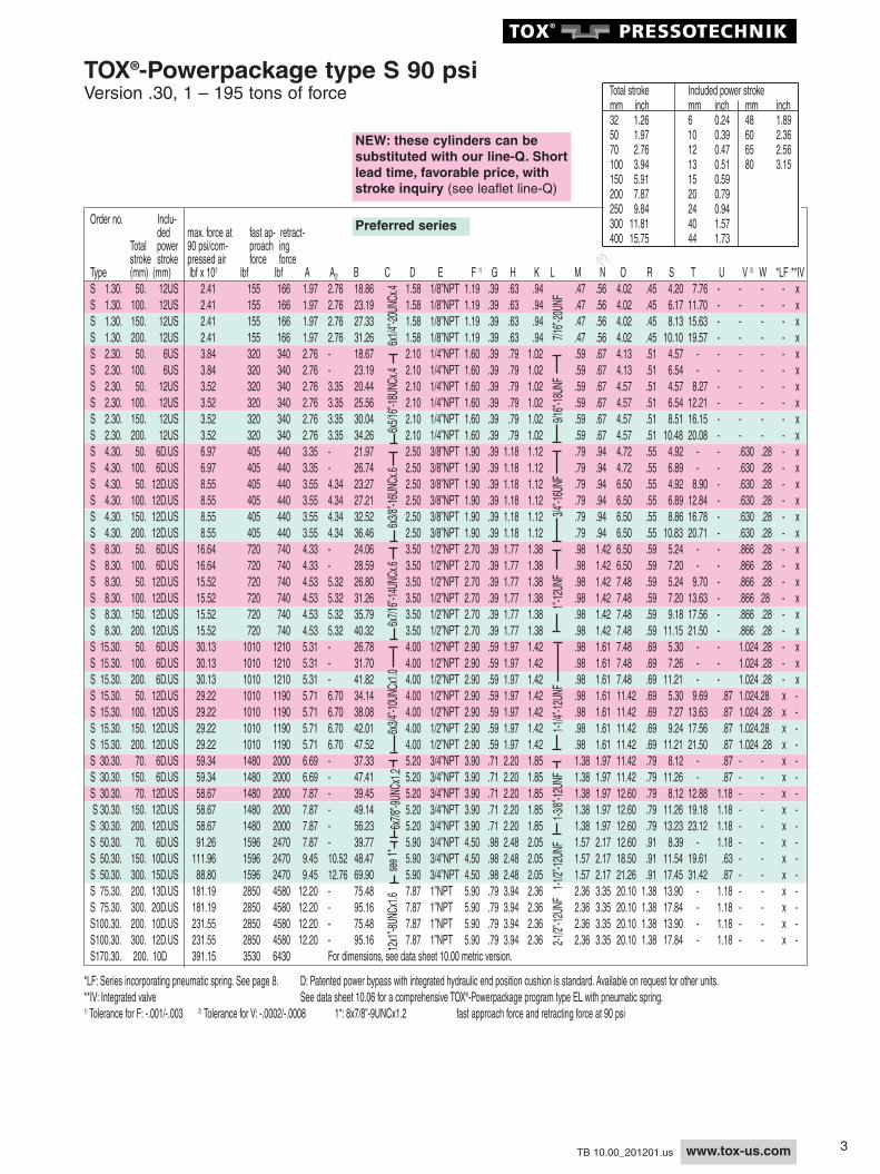
TOX®-Powerpackage type S 90 psiVersion .30, 1 – 195 tons of forcePatented power bypass with integrated retract hydraulic cushionis a standard feature for all TOX®-Powerpackages type S 4 to S 170.
D
S 15-30
C
AA2
O
N
C
A
A2
O
N
D
S 1 S 8–
3www.tox-us.comTB 10.00_201201.us
Order no. Inclu-ded max. force at fast ap- retract-
Total power 90 psi/com- proach ingstroke stroke pressed air force force
Total stroke Included power strokemm inch mm inch mm inch32 1.26 6 0.24 48 1.8950 1.97 10 0.39 60 2.3670 2.76 12 0.47 65 2.56100 3.94 13 0.51 80 3.15150 5.91 15 0.59200 7.87 20 0.79250 9.84 24 0.94300 11.81 40 1.57400 15.75 44 1.73
Preferred series
NEW: these cylinders can besubstituted with our line-Q. Shortlead time, favorable price, withstroke inquiry (see leaflet line-Q)
TOX®-Powerpackage type S 90 psiVersion .30, 1 – 195 tons of force
*LF: Series incorporating pneumatic spring. See page 8. D: Patented power bypass with integrated hydraulic end position cushion is standard. Available on request for other units.**IV: Integrated valve See data sheet 10.06 for a comprehensive TOX®-Powerpackage program type EL with pneumatic spring.1) Tolerance for F: -.001/-.003 2) Tolerance for V: -.0002/-.0008 1*: 8x7/8”-9UNCx1.2 fast approach force and retracting force at 90 psi
4 www.tox-us.com TB 10.00_201201.us
Order no. Inclu-ded max. force at fast ap- retract-
Total power compressed air proach ingstroke stroke 90 psi 145 psi force force
Type (mm) (mm) lbf x 103 lbf x 103 lbf lbf A A2 B C D E F 1) G H K LS1. 32. 6 US 1.26 2.25 258 270 1.97 – 14.18 1.60 1/8”NPT 1.20 .39 .63 .94S1. 100. 6 US 1.26 2.25 258 270 1.97 – 20.75 1.60 1/8”NPT 1.20 .39 .63 .94S1. 150. 6 US 1.26 2.25 258 270 1.97 – 25.48 1.60 1/8”NPT 1.20 .39 .63 .94S1. 200. 6 US 1.26 2.25 258 270 1.97 – 30.20 1.60 1/8”NPT 1.20 .39 .63 .94S1. 50. 12 US 1.26 2.25 258 270 1.97 – 17.1 1.60 1/8”NPT 1.20 .39 .63 .94S1. 100. 12 US 1.26 2.25 258 270 1.97 – 22.3 1.60 1/8”NPT 1.20 .39 .63 .94S1. 150. 12 US 1.26 2.25 258 270 1.97 – 27.0 1.60 1/8”NPT 1.20 .39 .63 .94S1. 200. 12 US 1.26 2.25 258 270 1.97 – 31.7 1.60 1/8”NPT 1.20 .39 .63 .94S1. 250. 12 US 1.58 2.70 258 270 1.97 2.76 34.7 1.60 1/8”NPT 1.20 .39 .63 .94S1. 50. 24 US 1.58 2.70 258 270 1.97 2.76 18.9 1.60 1/8”NPT 1.20 .39 .63 .94S1. 100. 24 US 1.58 2.70 258 270 1.97 2.76 23.2 1.60 1/8”NPT 1.20 .39 .63 .94S1. 150. 24 US 1.58 2.70 258 270 1.97 2.76 27.3 1.60 1/8”NPT 1.20 .39 .63 .94S1. 200. 24 US 1.58 2.70 258 270 1.97 2.76 31.3 1.60 1/8”NPT 1.20 .39 .63 .94
Total stroke Included power strokemm inch mm inch mm inch32 1.26 6 0.24 48 1.8950 1.97 10 0.39 60 2.3670 2.76 12 0.47 65 2.56100 3.94 13 0.51 80 3.15150 5.91 15 0.59200 7.87 20 0.79250 9.84 24 0.94300 11.81 40 1.57400 15.75 44 1.73
S 8 – S 15, with biggertransducer (A2) and air spring
Return stroke
Fastapproachstroke
SRE
M KG
ET
B U
LØH
ØF
7 2 3 6 9 4851
S
Return stroke
RE
GKM
W
ØF
ØH
ØVL Ø
F
TB
E
Fast approach stroke
C
A
A2
O
N
D
S 1 S 8–
17 4
O
A
N
C
D
S 2 - S 15
5632
B
G
KM
W
LØ H
Ø F
ØV
S
E E
R
Rückhub EilhubReturn stroke
View Y
Fast approach stroke
Y
Preferred series
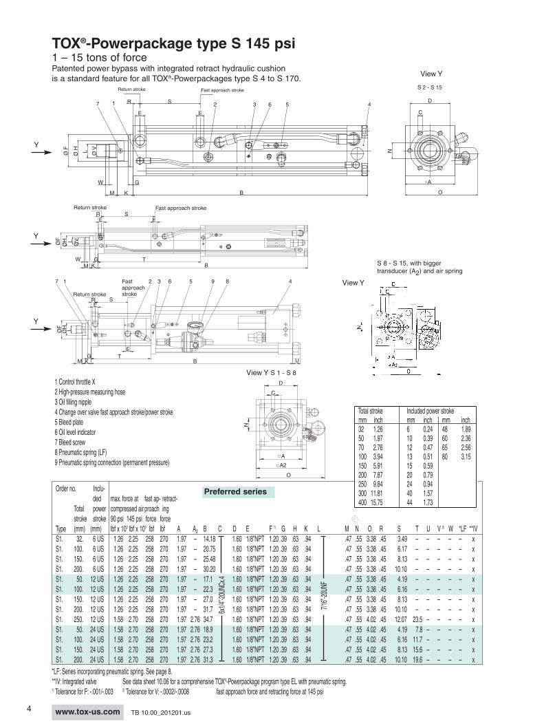
TOX®-Powerpackage type S 145 psi1 – 15 tons of forcePatented power bypass with integrated retract hydraulic cushionis a standard feature for all TOX®-Powerpackages type S 4 to S 170.
1 Control throttle X2 High-pressure measuring hose3 Oil filling nipple4 Change over valve fast approach stroke/power stroke5 Bleed plate6 Oil level indicator7 Bleed screw8 Pneumatic spring (LF)9 Pneumatic spring connection (permanent pressure)
*LF: Series incorporating pneumatic spring. See page 8.**IV: Integrated valve See data sheet 10.06 for a comprehensive TOX®-Powerpackage program type EL with pneumatic spring.1) Tolerance for F: -.001/-.003 2) Tolerance for V: -.0002/-.0008 fast approach force and retracting force at 145 psi
S 1 – S 8
5www.tox-us.comTB 10.00_201201.us
Order no. Included max. force at fast ap- retract-Total power compressed air proach ingstroke stroke 90 psi 145 psi force force
Type (mm) ( mm) lbf x103 lbf x103 lbf lbf A A2 B C D E F 1) G H K L
Total stroke Included power strokemm inch mm inch mm inch32 1.26 6 0.24 48 1.8950 1.97 10 0.39 60 2.3670 2.76 12 0.47 65 2.56100 3.94 13 0.51 80 3.15150 5.91 15 0.59200 7.87 20 0.79250 9.84 24 0.94300 11.81 40 1.57400 15.75 44 1.73
6x3/8”-16UNCx.6
3/4”-16UNF
6x1/4”-20UNCx.4
7/16”-20UNF
6x5/16”-18UNCx.4
9/16”-18UNF
Preferred series
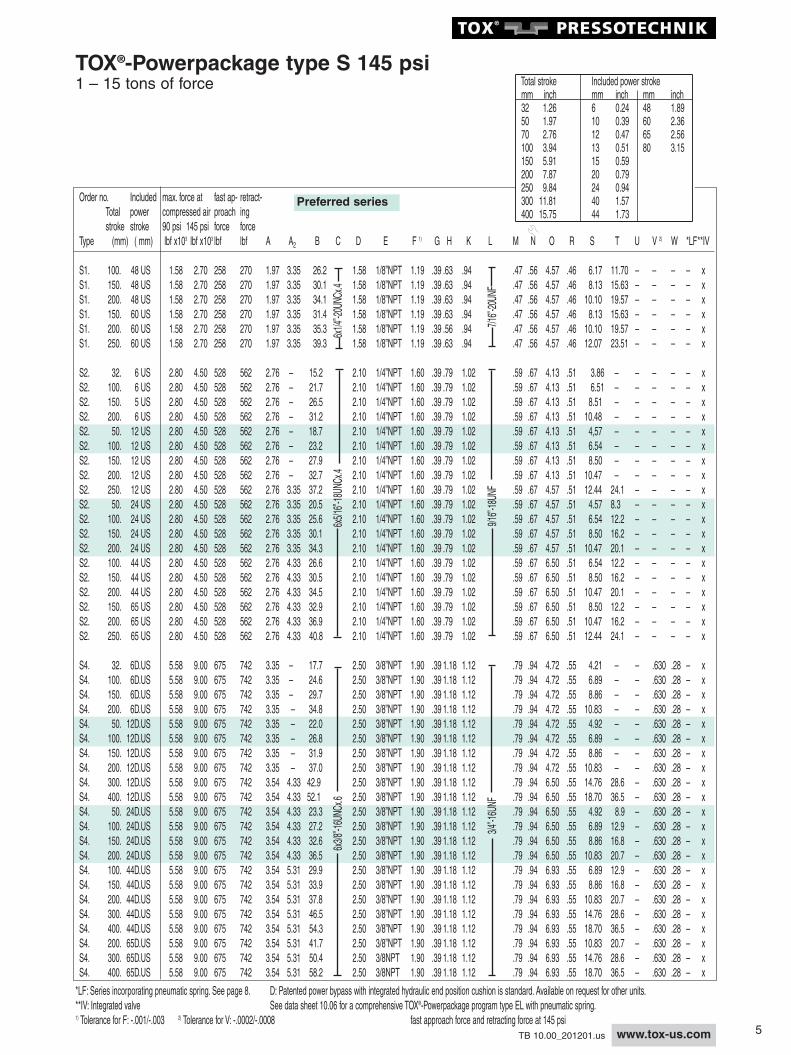
TOX®-Powerpackage type S 145 psi1 – 15 tons of force
*LF: Series incorporating pneumatic spring. See page 8. D: Patented power bypass with integrated hydraulic end position cushion is standard. Available on request for other units.**IV: Integrated valve See data sheet 10.06 for a comprehensive TOX®-Powerpackage program type EL with pneumatic spring.1) Tolerance for F: -.001/-.003 2) Tolerance for V: -.0002/-.0008 fast approach force and retracting force at 145 psi
6 www.tox-us.com TB 10.00_201201.us
M N O R S T U V 2) W *LF *IV
.98 1.42 6.50 .59 4.53 – – .866 .28 – x
.98 1.42 6.50 .59 7.21 – – .866 .28 – x
.98 1.42 6.50 .59 9.18 – – .866 .28 – x
.98 1.42 6.50 .59 11.15 – – .866 .28 – x
.98 1.42 6.50 .59 5.24 – – .866 .28 – x
.98 1.42 6.50 .59 7.20 – – .866 .28 – x
.98 1.42 6.50 .59 9.17 – – .866 .28 – x
.98 1.42 6.50 .59 11.14 – – .866 .28 – x
.98 1.42 6.93 .59 15.08 29.4 – .866 .28 – x
.98 1.42 6.93 .59 19.02 37.3 – .866 .28 – x
.98 1.42 6.93 .59 5.24 9.7 – .866 .28 – x
.98 1.42 6.93 .59 7.20 13.6 – .866 .28 – x
.98 1.42 6.93 .59 9.17 17.6 – .866 .28 – x
.98 1.42 6.93 .59 11.14 21.5 – .866 .28 – x
.98 1.42 11.42 .59 7.20 13.6 .87 .866 .28 x –
.98 1.42 11.42 .59 9.17 17.6 .87 .866 .28 x –
.98 1.42 11.42 .59 11.14 21.5 .87 .866 .28 x –
.98 1.42 11.42 .59 15.08 29.4 .87 .866 .28 x –
.98 1.42 11.42 .59 19.02 37.3 .87 .866 .28 x –
.98 1.42 12.60 .59 11.14 21.5 1.18 .866 .28 x –
.98 1.42 12.60 .59 15.08 29.4 1.18 .866 .28 x –
.98 1.42 12.60 .59 19.02 37.3 1.18 .866 .28 x –
.98 1.61 6.93 .69 4.59 – – 1.024 .28 – x
.98 1.61 6.93 .69 7.27 – – 1.024 .28 – x
.98 1.61 6.93 .69 9.24 – – 1.024 .28 – x
.98 1.61 6.93 .69 11.21 – – 1.024 .28 – x
.98 1.61 6.93 .69 5.30 – – 1.024 .28 – x
.98 1.61 6.93 .69 7.26 – – 1.024 .28 – x
.98 1.61 6.93 .69 9.23 – – 1.024 .28 – x
.98 1.61 6.93 .69 11.20 – – 1.024 .28 – x
.98 1.61 11.42 .69 15.14 29.4 .87 1.024 .28 x –
.98 1.61 11.42 .69 19.07 37.3 .87 1.024 .28 x –
.98 1.61 11.42 .69 5.30 9.7 .87 1.024 .28 x –
.98 1.61 11.42 .69 7.26 13.6 .87 1.024 .28 x –
.98 1.61 11.42 .69 9.23 17.6 .87 1.024 .28 x –
.98 1.61 11.42 .69 11.20 21.5 .87 1.024 .28 x –
.98 1.61 12.60 .69 7.26 13.6 1.18 1.024 .28 x –
.98 1.61 12.60 .69 9.23 17.6 1.18 1.024 .28 x –
.98 1.61 12.60 .69 11.20 21.5 1.18 1.024 .28 x –
.98 1.61 12.60 .69 15.14 29.4 1.18 1.024 .28 x –
.98 1.61 12.60 .69 19.07 37.3 1.18 1.024 .28 x –
.98 1.61 12.60 .69 9.23 17.6 1.18 1.024 .28 x –
.98 1.61 12.60 .69 11.20 21.5 1.18 1.024 .28 x –
.98 1.61 12.60 .69 15.14 29.4 1.18 1.024 .28 x –
.98 1.61 12.60 .69 19.07 37.3 1.18 1.024 .28 x –
Order no. Included max. force at fast ap- retract-Total power compressed air proach ingstroke stroke 90 psi 145 psi force force
Type ( mm) (mm) lbf x 103 lbf x 103 lbf lbf A A2 B C D E F 1) G H K L
Total stroke Included power strokemm inch mm inch mm inch32 1.26 6 0.24 48 1.8950 1.97 10 0.39 60 2.3670 2.76 12 0.47 65 2.56100 3.94 13 0.51 80 3.15150 5.91 15 0.59200 7.87 20 0.79250 9.84 24 0.94300 11.81 40 1.57400 15.75 44 1.73
6x7/16”-14UNCx.6
1”-12UNF
6x3/4”-10UNCx1.0
1-1/4”-12UNF
Preferred series
TOX®-Powerpackage type S 145 psi1 – 15 tons of force
*LF: Series incorporating pneumatic spring. See page 8. D: Patented power bypass with integrated hydraulic end position cushion is standard. Available on request for other units.**IV: Integrated valve See data sheet 10.06 for a comprehensive TOX®-Powerpackage program type EL with pneumatic spring.1) Tolerance for F: -.001/-.003 2) Tolerance for V: -.0002/-.0008 fast approach force and retracting force at 145 psi
7www.tox-us.comTB 10.00_201201.us
D
S 50
C
A
A2
O
N
D
S 15-30
C
AA2
O
N
Order no. Inclu-ded max.force at fast ap- retract-
Total power compressed air proach ingstroke stroke 90 psi 145 psi force force
Total stroke Included power strokemm inch mm inch mm inch32 1.26 6 0.24 48 1.8950 1.97 10 0.39 60 2.3670 2.76 12 0.47 65 2.56100 3.94 13 0.51 80 3.15150 5.91 15 0.59200 7.87 20 0.79250 9.84 24 0.94300 11.81 40 1.57400 15.75 44 1.73
6x7/8”-9UNCx1.2
1-3/8”-12UNF
Y
View YView Y
View YView Y View YView YD
S 170
A
O
C
D
S 75/100
C
AO
N
Return stroke
Fastapproachstroke
SRE
M KG
ET
B U
LØH
ØF
7 2 3 6 9 4851
Y
R
483 5 9217 6
S
E
M K
G
B U
W E
ØF
ØV
ØH L
Preferred series
TOX®-Powerpackage type S 145 psi33 – 189 tons of force
Patented power bypass with integrated retract hydraulic cushionis a standard feature for all TOX®-Powerpackages type S 4 to S 170.
1 Control throttle X2 High-pressure measuring hose3 Oil filling nipple4 Change over valve fast approach stroke/power stroke5 Bleed plate6 Oil level indicator7 Bleed screw8 Pneumatic spring (LF)9 Pneumatic spring connection (permanent pressure)
*LF: Series incorporating pneumatic spring. See page 8. D: Patented power bypass with integrated hydraulic end position cushion is standard. Available on request for other units.See data sheet 10.06 for a comprehensive TOX®-Powerpackage program type EL with pneumatic spring.
1) Tolerance for F: -.001/-.003 fast approach force and retracting force at 145 psi
8 www.tox-us.com TB 10.00_201201.us
Order no. Inclu-ded max. force at fast ap- retract-
Total power compressed air proach ingstroke stroke 90 psi 145 psi force force
Total stroke Included power strokemm inch mm inch mm inch32 1.26 6 0.24 48 1.8950 1.97 10 0.39 60 2.3670 2.76 12 0.47 65 2.56100 3.94 13 0.51 80 3.15150 5.91 15 0.59200 7.87 20 0.79250 9.84 24 0.94300 11.81 40 1.57400 15.75 44 1.73
6x7/8”-9UNCx1.2
1 3/8”-12UNF
8x7/8”-9UNCx1.2
12x1”-8UNCx1.6
1-1/2”-12UNF
2.1/2”-12UNF
2.1/2”-12UNF
12x1”-8UNCx1.6
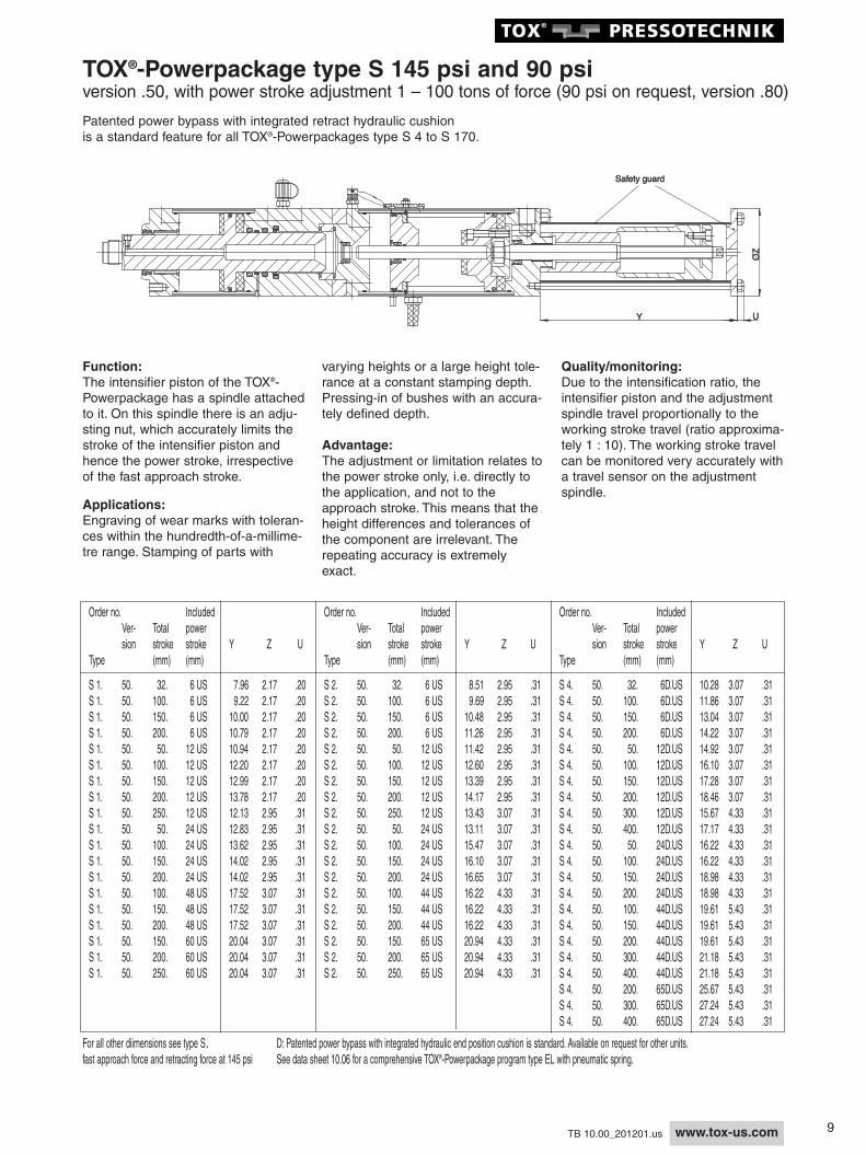
Intensifier Air Spring type LFThe feed piston inside the intensifier section is spring loadedto allow mounting of the Powerpackage in any orientation. Insome TOX®- Powerpackages, the mechanical spring is replac -ed by a special regulator set at low pressure (8 bar = 12 psi).This regulator must be plumbed with a constant air supply.The regulator is supplied with the cylinder.
Pressure Regulator
0.8 bar G 3/8
Air supply 3 - 10 bar (30 - 145 psi)
Preferred series
TOX®-Powerpackage type S 145 psi33 – 189 tons of force
*LF: Series incorporating pneumatic spring. D: Patented power bypass with integrated hydraulic end position cushion is standard. Available on request for other units.See data sheet 10.06 for a comprehensive TOX®-Powerpackage program type EL with pneumatic spring.1) Tolerance for F: -.001/-.003 fast approach force and retracting force at 145 psi
9www.tox-us.comTB 10.00_201201.us
Order no. Included Order no. Included Order no. IncludedVer- Total power Ver- Total power Ver- Total powersion stroke stroke Y Z U sion stroke stroke Y Z U sion stroke stroke Y Z U
Type (mm) (mm) Type (mm) (mm) Type (mm) (mm)
S 1. 50. 32. 6 US 7.96 2.17 .20 S 2. 50. 32. 6 US 8.51 2.95 .31 S 4. 50. 32. 6D.US 10.28 3.07 .31S 1. 50. 100. 6 US 9.22 2.17 .20 S 2. 50. 100. 6 US 9.69 2.95 .31 S 4. 50. 100. 6D.US 11.86 3.07 .31S 1. 50. 150. 6 US 10.00 2.17 .20 S 2. 50. 150. 6 US 10.48 2.95 .31 S 4. 50. 150. 6D.US 13.04 3.07 .31S 1. 50. 200. 6 US 10.79 2.17 .20 S 2. 50. 200. 6 US 11.26 2.95 .31 S 4. 50. 200. 6D.US 14.22 3.07 .31S 1. 50. 50. 12 US 10.94 2.17 .20 S 2. 50. 50. 12 US 11.42 2.95 .31 S 4. 50. 50. 12D.US 14.92 3.07 .31S 1. 50. 100. 12 US 12.20 2.17 .20 S 2. 50. 100. 12 US 12.60 2.95 .31 S 4. 50. 100. 12D.US 16.10 3.07 .31S 1. 50. 150. 12 US 12.99 2.17 .20 S 2. 50. 150. 12 US 13.39 2.95 .31 S 4. 50. 150. 12D.US 17.28 3.07 .31S 1. 50. 200. 12 US 13.78 2.17 .20 S 2. 50. 200. 12 US 14.17 2.95 .31 S 4. 50. 200. 12D.US 18.46 3.07 .31S 1. 50. 250. 12 US 12.13 2.95 .31 S 2. 50. 250. 12 US 13.43 3.07 .31 S 4. 50. 300. 12D.US 15.67 4.33 .31S 1. 50. 50. 24 US 12.83 2.95 .31 S 2. 50. 50. 24 US 13.11 3.07 .31 S 4. 50. 400. 12D.US 17.17 4.33 .31S 1. 50. 100. 24 US 13.62 2.95 .31 S 2. 50. 100. 24 US 15.47 3.07 .31 S 4. 50. 50. 24D.US 16.22 4.33 .31S 1. 50. 150. 24 US 14.02 2.95 .31 S 2. 50. 150. 24 US 16.10 3.07 .31 S 4. 50. 100. 24D.US 16.22 4.33 .31S 1. 50. 200. 24 US 14.02 2.95 .31 S 2. 50. 200. 24 US 16.65 3.07 .31 S 4. 50. 150. 24D.US 18.98 4.33 .31S 1. 50. 100. 48 US 17.52 3.07 .31 S 2. 50. 100. 44 US 16.22 4.33 .31 S 4. 50. 200. 24D.US 18.98 4.33 .31S 1. 50. 150. 48 US 17.52 3.07 .31 S 2. 50. 150. 44 US 16.22 4.33 .31 S 4. 50. 100. 44D.US 19.61 5.43 .31S 1. 50. 200. 48 US 17.52 3.07 .31 S 2. 50. 200. 44 US 16.22 4.33 .31 S 4. 50. 150. 44D.US 19.61 5.43 .31S 1. 50. 150. 60 US 20.04 3.07 .31 S 2. 50. 150. 65 US 20.94 4.33 .31 S 4. 50. 200. 44D.US 19.61 5.43 .31S 1. 50. 200. 60 US 20.04 3.07 .31 S 2. 50. 200. 65 US 20.94 4.33 .31 S 4. 50. 300. 44D.US 21.18 5.43 .31S 1. 50. 250. 60 US 20.04 3.07 .31 S 2. 50. 250. 65 US 20.94 4.33 .31 S 4. 50. 400. 44D.US 21.18 5.43 .31
For all other diimensions see type S. D: Patented power bypass with integrated hydraulic end position cushion is standard. Available on request for other units.fast approach force and retracting force at 145 psi See data sheet 10.06 for a comprehensive TOX®-Powerpackage program type EL with pneumatic spring.
Safety guardSafety guard
ØZ
ØZ
YY UU
Quality/monitoring:Due to the intensification ratio, theintensifier piston and the adjustmentspindle travel proportionally to theworking stroke travel (ratio approxima-tely 1 : 10). The working stroke travelcan be monitored very accurately witha travel sensor on the adjustmentspindle.
Function:The intensifier piston of the TOX®-Powerpackage has a spindle attachedto it. On this spindle there is an adju-sting nut, which accurately limits thestroke of the intensifier piston andhence the power stroke, irrespectiveof the fast approach stroke.
Applications:Engraving of wear marks with toleran-ces within the hundredth-of-a-millime-tre range. Stamping of parts with
varying heights or a large height tole-rance at a constant stamping depth.Pressing-in of bushes with an accura-tely defined depth.
Advantage:The adjustment or limitation relates tothe power stroke only, i.e. directly tothe application, and not to theapproach stroke. This means that theheight differences and tolerances ofthe component are irrelevant. Therepeating accuracy is extremelyexact.
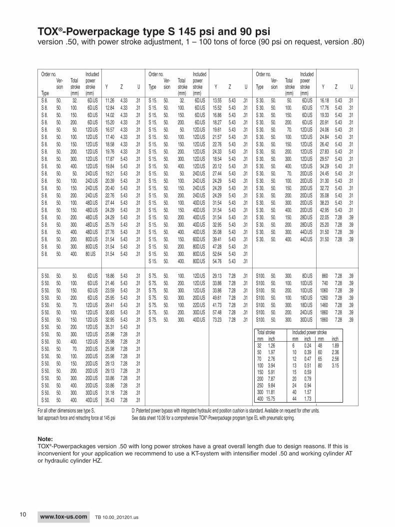
TOX®-Powerpackage type S 145 psi and 90 psiversion .50, with power stroke adjustment 1 – 100 tons of force (90 psi on request, version .80)
Patented power bypass with integrated retract hydraulic cushionis a standard feature for all TOX®-Powerpackages type S 4 to S 170.
10 www.tox-us.com TB 10.00_201201.us
Note:TOX®-Powerpackages version .50 with long power strokes have a great overall length due to design reasons. If this isinconvenient for your application we recommend to use a KT-system with intensifier model .50 and working cylinder ATor hydraulic cylinder HZ.
Order no. Included Order no. Included Order no. IncludedVer- Total power Ver- Total power Ver- Total powersion stroke stroke Y Z U Type sion stroke stroke Y Z U Type sion stroke stroke Y Z U
Total stroke Included power strokemm inch mm inch mm inch32 1.26 6 0.24 48 1.8950 1.97 10 0.39 60 2.3670 2.76 12 0.47 65 2.56100 3.94 13 0.51 80 3.15150 5.91 15 0.59200 7.87 20 0.79250 9.84 24 0.94300 11.81 40 1.57400 15.75 44 1.73
For all other diimensions see type S. D: Patented power bypass with integrated hydraulic end position cushion is standard. Available on request for other units.fast approach force and retracting force at 145 psi See data sheet 10.06 for a comprehensive TOX®-Powerpackage program type EL with pneumatic spring.
TOX®-Powerpackage type S 145 psi and 90 psiversion .50, with power stroke adjustment, 1 – 100 tons of force (90 psi on request, version .80)
11www.tox-us.comTB 10.00_201201.us
Order no. Inclu-ded max. force at fast ap- retract-
Total power 90 psi/com- proach ingstroke stroke pressed air force force
Type (mm) (mm) lbf x 103 lbf lbf A A2 B C D E F 1) G H K LK 1.30 100. 6 US 2.41 155 166 1.97 2.76 12.7 1.60 1/8”NPT 1.20 .39 .63 .94K 1.30 200. 10 US 2.41 155 166 1.97 2.76 20.2 1.60 1/8”NPT 1.20 .39 .63 .94K 2.30 100. 5 US 3.52 320 340 2.76 3.35 12.9 2.10 1/4”NPT 1.60 .39 .79 1.02K 2.30 200. 12 US 3.52 320 340 2.76 3.35 20.8 2.10 1/4”NPT 1.60 .39 .79 1.02K 4.30 100. 5 US 8.55 405 440 3.35 4.33 13.9 2.50 3/8”NPT 1.90 .39 1.18 1.12K 4.30 200. 10 US 8.55 405 440 3.35 4.33 21.8 2.50 3/8”NPT 1.90 .39 1.18 1.12K 8.30 100. 5 US 15.52 715 740 4.33 5.31 14.4 3.50 1/2”NPT 2.70 .39 1.77 1.38K 8.30 200. 10 US 15.52 715 740 4.33 5.31 22.3 3.50 1/2”NPT 2.70 .39 1.77 1.38K15.30. 100. 10 US 29.23 1010 1191 5.31 7.87 23.0 4.00 1/2”NPT 2.90 .59 1.97 1.42K15.30. 200. 10 US 29.23 1010 1191 5.31 7.87 25.4 4.00 1/2”NPT 2.90 .59 1.97 1.42K30.30. 200. 10 US 72.17 1480 2000 6.69 10.51 29.2 5.20 3/4”NPT 3.90 .71 2.20 1.85K50.30. 100. 10 US 88.80 1596 2470 7.87 12.76 28.2 5.91 3/4”NPT 4.53 .98 2.48 2.05K50.30. 200. 10 US 88.80 1596 2470 7.87 12.76 30.9 5.91 3/4”NPT 4.53 .98 2.48 2.05K 75.30. 200. 10D 179.84 2830 4946 For dimensions, see data sheet 10.00, metric version.K100.30. 200. 10D 242.78 2830 4946 For dimensions, see data sheet 10.00, metric version.K170.30. 200. 10D 359.68 3530 6430 For dimensions, see data sheet 10.00, metric version.
Total stroke Included power strokemm inch mm inch mm inch32 1.26 6 0.24 48 1.8950 1.97 10 0.39 60 2.3670 2.76 12 0.47 65 2.56100 3.94 13 0.51 80 3.15150 5.91 15 0.59200 7.87 20 0.79250 9.84 24 0.94300 11.81 40 1.57400 15.75 44 1.73
1*2*
8*9*
10*3*
5*
12*
14*
7*6*
13*
4* 11*
C
D
K 75/100
O
A
A2
ND
K 170
O
A
N
A2
K 50
A
A2O
DN
C
BMG
Return strokeR
ES
E
Fast approach stroke
X
LØH
ØF
P
K U
4 2 9 6 3 7581
OO
A2A2
CC
NN
DDAA
K 8 - K 30K 8 - K 30 1 Control throttle X2 High-pressure measuring hose3 Oil filling nipple4 Change over valve fast approachstroke/power stroke
5 Bleed plate6 Oil level indicator7 Bleed screw8 Pneumatic spring (LF)9 Pneumatic spring connection (permanent pressure)
A2A2OO
CC
NN
DDAA
K 1 - K 15K 1 - K 15
W
R
Return stroke
B
Fast approach stroke
E
X
5241
L
L
ØH
ØF
ØV
6 3 7
U
P
SE
G
M K
Y
View YView Y View Y
Y
View Y K 1 – 8 View Y K 15/30
Preferred series
NEW: these cylinders can besubstituted with our line-Q. Shortlead time, favorable price, withstroke inquiry (see leaflet line-Q)
TOX®-Powerpackage type K 90 psiversion .30, compact design, 1 – 180 tons of force
Patented power bypass with integrated retract hydraulic cushion is available on request.
*LF: Series incorporating pneumatic spring. See page 8. D: Patented power bypass with integrated hydraulic end position cushion is standard. Available on request for other units.**IV: Integrated valve See data sheet 10.06 for a comprehensive TOX®-Powerpackage program type EL with pneumatic spring.1) Tolerance for F: -.001/-.003 2) Tolerance for V: -.0002/-.0008 fast approach force and retracting force at 90 psi
12 www.tox-us.com TB 10.00_201201.us
W
R
Return stroke
B
Fast approach stroke
E
X
5241
L
L
ØH
ØF
ØV
6 3 7
U
P
SE
G
M K
A2A2OO
CC
NN
DDAA
K 1-8K 1-8
OO
A2A2
CC
NN
C
DDAA
K 50
A
A2O
DN
C
Order no. Inclu-ded max. force at fast ap- retract-
Total power compressed air proach ingstroke stroke 90 psi 145 psi force force
Total stroke Included power strokemm inch mm inch mm inch32 1.26 6 0.24 48 1.8950 1.97 10 0.39 60 2.3670 2.76 12 0.47 65 2.56100 3.94 13 0.51 80 3.15150 5.91 15 0.59200 7.87 20 0.79250 9.84 24 0.94300 11.81 40 1.57400 15.75 44 1.73
6x1/4”-20UNCx.4
7/16”-20UNF
6x5/16”-18UNCx.4
6x3/8”-16UNCx.6
9/16”-18UNF
3/4”-16UNF
Y
View Y View Y
Y
View Y
C
D
K 75/100
O
A
A2
ND
K 170
O
A
N
A2
*LF: Series incorporating pneumatic spring. See page 8. **IV: Integrated valve See data sheet 10.06 for a comprehensive TOX®-Powerpackage program type EL with pneumatic spring.1) Tolerance for F: -.001/-.003 2) Tolerance for V: -.0002/-.0008 fast approach force and retracting force at 145 psi
BMG
Return strokeR
ES
E
Fast approach stroke
X
LØH
ØF
PK U
4 2 9 6 3 7581
View Y K 1 – K 15 View Y K 8 – K 30
Preferred series
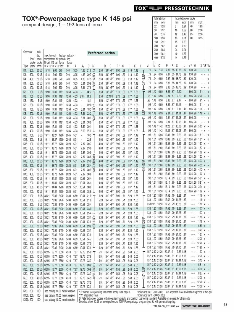
TOX®-Powerpackage type K 145 psicompact design, 1 – 192 tons of force
Patented power bypass with integrated retract hydraulic cushion is available on request.
1 Control throttle X2 High-pressure measuring hose3 Oil filling nipple4 Change over valve fast approachstroke/power stroke
5 Bleed plate6 Oil level indicator7 Bleed screw8 Pneumatic spring (LF)9 Pneumatic spring connection (permanent pressure)
13www.tox-us.comTB 10.00_201201.us
Total stroke Included power strokemm inch mm inch mm inch32 1.26 6 0.24 48 1.8950 1.97 10 0.39 60 2.3670 2.76 12 0.47 65 2.56100 3.94 13 0.51 80 3.15150 5.91 15 0.59200 7.87 20 0.79250 9.84 24 0.94300 11.81 40 1.57400 15.75 44 1.73
Order no. Inclu-ded max. force at fast ap- retract-
Total power compressed air proach ingstroke stroke 90 psi 145 psi force force
*LF: Series incorporating pneumatic spring. See page 8. 1) Tolerance for F: -.001/-.003**IV: Integrated valve 2) Tolerance for V: -.0002/-.0008D: Patented power bypass with integrated hydraulic end position cushion is standard. Available on request for other units.See data sheet 10.06 for a comprehensive TOX®-Powerpackage program type EL with pneumatic spring.
Total stroke Included power strokemm inch mm inch mm inch32 1.26 6 0.24 48 1.8950 1.97 10 0.39 60 2.3670 2.76 12 0.47 65 2.56100 3.94 13 0.51 80 3.15150 5.91 15 0.59200 7.87 20 0.79250 9.84 24 0.94300 11.81 40 1.57400 15.75 44 1.73
6x1/4”-20UNCx.4
7/16”-20UNF
6x5/16”-18UNCx.4
9/16”-18UNF
6x3/8”-16UNCx.6
3/4”-16UNF
Y
Y
View Y
View YView Y K 50
A
A2O
DN
C
K 1 – K 8
K 8 – K 30
*LF: Series incorporating pneumatic spring. See page 8. **IV: Integrated valve See data sheet 10.06 for a comprehensive TOX®-Powerpackage program type EL with pneumatic spring.1) Tolerance for F: -.001/-.003 2) Tolerance for V: -.0002/-.0008 fast approach force and retracting force at 145 psi
TOX®-Powerpackage type K 145 psi and 90 psiversion .51, compact design with total stroke adjustment, 1 – 50 tons of force(90 psi on request, version .81)Stroke length and hence LDC position adjustable. For pulling operations a special execution is available.Patented power bypass with integrated retract hydraulic cushion is available on request.
Total stroke Included power strokemm inch mm inch mm inch32 1.26 6 0.24 48 1.8950 1.97 10 0.39 60 2.3670 2.76 12 0.47 65 2.56100 3.94 13 0.51 80 3.15150 5.91 15 0.59200 7.87 20 0.79250 9.84 24 0.94300 11.81 40 1.57400 15.75 44 1.73
6x3/8”-16UNCx.6
3/4”-16UNF
6x7/16”-14UNCx.6
1”-12UNF
6x3/4”-10UNCx1.0
11/4”-12UNF
6x7/8”-9UNCx1.2
13/8”-12UNF
6x7/8-9U
NCx1.2
11/2”-12UNF
TOX®-Powerpackage type K 145 psi and90 psiversion .51, compact design with total stroke adjustment,1 – 50 tons of force (90 psi on request, version .81)
*LF: Series incorporating pneumatic spring. See page 8. D: Patented power bypass with integrated hydraulic end position cushion is standard. Available on request for other units.**IV: Integrated valve See data sheet 10.06 for a comprehensive TOX®-Powerpackage program type EL with pneumatic spring.1) Tolerance for F: -.001/-.003 2) Tolerance for V: -.0002/-.0008 fast approach force and retracting force at 145 psi
16 www.tox-us.com TB 10.00_201201.us
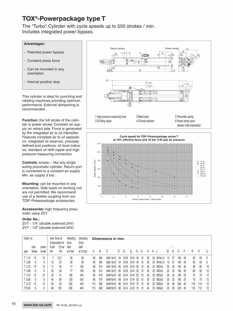
TOX®-Powerpackage type TThe "Turbo" Cylinder with cycle speeds up to 550 strokes / min.Includes integrated power bypass.
Order no. max. force at retracting retractingcompressed air force force
total power 6 bar 10 bar daN daNtype stroke stroke kN kN at 6 bar at 10 bar A B C D E1 E2 Ff7 G H K L
This cylinder is ideal for punching andnibbling machines providing optimumperformance. External dampening isrecommended.
Function: the full stroke of the cylin-der is power stroke. Constant air sup-ply on retract side. Force is generatedby the integrated air to oil intensifier.Features complete air to oil separati-on, integrated oil reservoir, preciselydefined end positions, oil level indica-tor, standard oil refill nipple and highpressure measuring connection.
Controls: simple – like any singleacting pneumatic cylinder. Return portis connected to a constant air supply.Min. air supply 3 bar.
Mounting: can be mounted in anyorientation. Side loads on working rodare not permitted. We recommenduse of a flexible coupling from ourTOX®-Powerpackage accessories.
Function: fast approach via built-inspring. Pneumatic-hydraulic powerstroke activated at any point of fastapproach. Return stoke entirely pneu-matic. Force generated via pressureintensifier, absolute air/oil separation,integrated oil reservoir, oil level indi-cator and oil filling nipple, measuringand control connection for pressuregauge or pressure switch.This allows sequential functions to becontrolled, such as return stroke acti-vation, stamping depth adjustment,etc.
Change-over control from fastapproach to power stroke takes placeautomatically according to the rampressure principle. Valves are inclu-ded in the TOX®-Powerpackage as astandard supply. The speed of thechange-over control can be regulatedwith control throttle X.
Attention: in the pressureless statethe piston rod extends due to thespring-driven fast approach force. Return stroke air pressure:minimum 5 bar.
1 Control throttle X 4 Change over valve fast approach stroke/power stroke2 High-pressure measuring hose 5 Bleed plate3 Oil filling nipple 6 Oil level indicator
Power stroke E2Return stroke
36
Dimensions in mm.
18 www.tox-us.com TB 10.00_201201.us
TOX®-Powerpackage with "Safety Rod Catcher"Type ZSLSafe locking of cylinder rod in the event of air pressure loss
Function:The safety rod catcher is held openwith air pressure. Loss of air pressurewill cause the unit to clamp on thecylinder rod. The energy of the driftingor falling load is used to generate theclamping force. The clamping forceincreases as the load increases.Internal springs force wedges toclamp the cylinder rod once the airpressure drops. The rod catcher willprevent the cylinder rod from exten-ding unless the static holding force issurpassed. The clamping force isreleased by applying air pressure andretracting the load.
Unlocking pressure: min. 2 bar(30 psi)
Release pressure: 4 bar (58 psi)Max. operating pressure: 10 bar
(145 psi)
Advantages:- Rod catcher integrated on cylinder front flange- Compact design- Stroke independent- Simple controls- Clamps tighter with increasing load- Clamps rod for unlimited time- Approved by the German Occu-pational Safety Administration
Controls:Requires a 3/2 -way valve.
For most applications, use the dia-gram shown below. During eachcycle, the 3/2-way valve is actuatedelectrically and releases the rod cat-cher unit. In cases of air pressureloss, power failure, emergency stop,or other failure mode, the rod catcherclamps the cylinder rod and stops theload.
The clamp position can be monitoredwith proximity sensors. We offerappropriate sensors of 45 and 70 mmlength.
Recommendations:If the plant air pressure fluctuates,such as a pressure drop at the startof cycle, it is recommended to installa check valve in the air supply line tothe rod catcher control valve.If shock noises or vibration occurduring the release operation, a flowcontrol valve can be installed in theair supply line to the rod catcher con-trol valve.
Electrical controlElectrical controls must conform to allapplicable local and national regulati-ons for presses. The buyer is respon-sible for correct installation and main-tenance of safety systems.
Not included
19www.tox-us.comTB 10.00_201201.us
All TOX®-Powerpackages type S andK, except for S 1, S 2, K 1 and K 2,can be supplied with the "Safety RodCatcher" option.
Order no.S04.100.06D - ZSL
Accessory Safety Rod CatcherTOX®-Power-packageOrder-No.
Clamps 1 for Ø 12 mm sensors included with unit. Sensors are not included with unit. Sensors should have > 2 mmsensing range.
ØV
ØFA
ØH L
W
M K
G
LSL
L1
Safety rod catcher
Load direction
B
1
* Attention: max. retraction force of the cylinder must be considered.
Type LSL L1 Allowable For Required length[mm] Load* TOX®-Power- of sensors
[lbf x 102] package type [mm]
ZSL 04 200 G1/4 22.5 S 04, K 04, AT 04 45ZSL 08 200 G1/4 22.5 S 08, K 08, AT 08 45ZSL 15 250 G1/4 33.7 S 15, K 15, AT 15 45ZSL 30 256 G1/4 45 S 30, K 30, AT 30 70ZSL 50 275 G3/8 56 S 50, K 50, AT 50 70ZSL 100 on request G3/8 on request S 100, K 100, AT 100ZSL 170 414 G3/8 135 S 170, K 170, AT 170
Accessories (to be orderedseparately):Sensor M12x1x45Sensor M12x1x70Cable 5 m long.
20 www.tox-us.com TB 10.00_201201.us
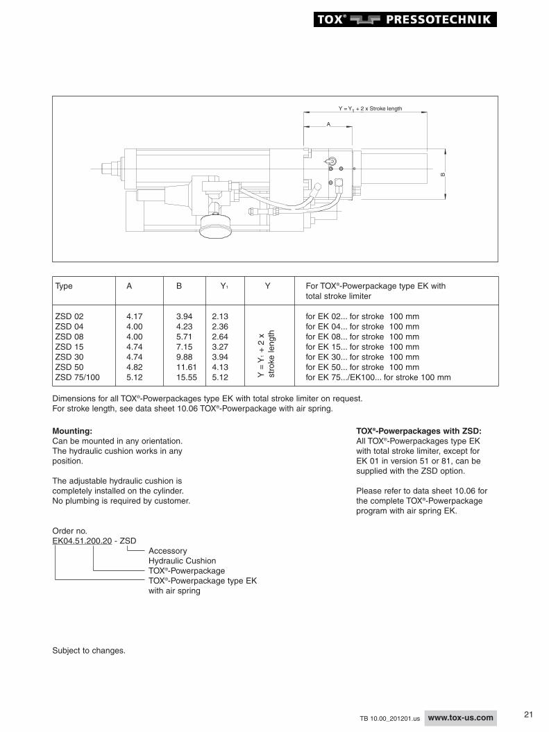
TOX®-Powerpackage type EK with Total Stroke Limiter and Adjustable End of Stroke CushionType ZSD, Hydraulic cushion for cutting impact damping
Advantages:- Hydraulic dampingof end of stroke- Cushioning infinitelyadjustable- Total stroke infinitelyadjustable- Can be mounted in any orientation- Protects tooling and machine- Reduces noise levels- Maintenance-free
Function:The adjusting nut (total stroke limiter)1 contacts the damping piston 2during approach or power strokedepending on the adjustment position.The damping piston 2 compresseshydraulic oil through the throttlingneedle 3. The damping effect can beadjusted with the throttling needle 3.During the return stroke, the dampingpiston 2 is pushed back to its originalposition by the pneumatic piston 4and through the integrated bypassvalves. The maximum damping strokeis approximately 7 mm.
Controls:Pneumatic controls same as for theTOX®-Powerpackage.
Ideal for damping in punching applica-tions and for smooth operation ofmachines during approach or powerstrokes. Available for all TOX®-Powerpackages type EK with totalstroke limiter.
1
2
3
4
21www.tox-us.comTB 10.00_201201.us
Order no.EK04.51.200.20 - ZSD
Accessory Hydraulic CushionTOX®-PowerpackageTOX®-Powerpackage type EKwith air spring
Subject to changes.
Mounting:Can be mounted in any orientation.The hydraulic cushion works in anyposition.
The adjustable hydraulic cushion iscompletely installed on the cylinder.No plumbing is required by customer.
Dimensions for all TOX®-Powerpackages type EK with total stroke limiter on request.For stroke length, see data sheet 10.06 TOX®-Powerpackage with air spring.
TOX®-Powerpackages with ZSD:All TOX®-Powerpackages type EKwith total stroke limiter, except forEK 01 in version 51 or 81, can besupplied with the ZSD option.
Please refer to data sheet 10.06 forthe complete TOX®-Powerpackageprogram with air spring EK.
A
Y = Y + 2 x Stroke length1
B
Type A B Y1 Y For TOX®-Powerpackage type EK withtotal stroke limiter
ZSD 02 4.17 3.94 2.13 for EK 02... for stroke 100 mmZSD 04 4.00 4.23 2.36 for EK 04... for stroke 100 mmZSD 08 4.00 5.71 2.64 for EK 08... for stroke 100 mmZSD 15 4.74 7.15 3.27 for EK 15... for stroke 100 mmZSD 30 4.74 9.88 3.94 for EK 30... for stroke 100 mmZSD 50 4.82 11.61 4.13 for EK 50... for stroke 100 mmZSD 75/100 5.12 15.55 5.12 for EK 75.../EK100... for stroke 100 mmY
= Y
1+ 2 x
stroke length
22 www.tox-us.com TB 10.00_201201.us
Accessories - Special Models
Tool holding fixture withanti-rotation lock VThe guide pin and bushing are includedin the delivery package. Please indicatethe total travel of the TOX®-Power-package when ordering. The center ofthe guide bushing bore must be set atdimension E from the centerline of thecylinder.Secure V/working rod with Loctite 222.
OO
ØAØA
ØBØB
DD
E ±0.001E ±0.001
View XView X
NNHH
KK
JJ
XX
ØLØL
ØFØFØGØG
MM
PPC
+To
tal s
trok
e of
po w
erpa
c kag
eC
+T o
t al s
t ro k
eo f
p ow
e rp a
c ka g
e
Mini ram guide with coupling ZWKThe center of the guide bushingbore must be set at dimension E1from the centerline of the cylinder.The bushings, posts and the couplingZWK are included in the deliverypackage.The centering hole allows accuratealignment of the ram plate for fini-shing work. Secure ZWK withLoctite 222.
ZWK 001.060.000VersionCoupling height in mmForceCoupling set
Coupling ZWKis threaded directly on the workingrod of the TOX®-Powerpackage andsecured with removable Loctite 222.This coupling provides a flexibleconnection between the TOX®-Powerpackage and die set, therebypreventing any side loads. Includesantirotation device.
ØF
D
H
For 6 boltmounting
ØB
J
V*
0.2
0
C
E I
A
GSW
Order no. for A ØB C D E ØF G H I J V* SW max. press max. TOX®-Power- force retractpackage [lbf x 10 ] force [lbf]
ZWK 001.060.000 US 2.36ZWK 001.070.000 US S 1 / K 1 US 2.76 7/16”-20UNF 0.63 2.91 1.73 0.87 1.10 1.71 0.87 4xM6x9 0.31 0.75 4.50 562ZWK 001.080.000 US 3.15ZWK 002.060.000 US 2.36ZWK 002.070.000 US S 2 / K 2 US 2.76 9/16”-18UNF 0.63 2.91 1.73 0.87 1.10 1.71 0.87 4xM6x9 0.31 0.75 4.50 562ZWK 002.080.000 US 3.15ZWK 004.060.000 US 2.36ZWK 004.070.000 US 2.76ZWK 004.080.000 US S 4 / K 4 US 3.15 3/4”-16UNF 0.83 3.31 2.05 1.18 1.10 2.07 1.18 4xM8x12 0.31 1.06 10.80 787ZWK 004.090.000 US 3.54ZWK 004.100.000 US 3.94ZWK 008.070.000 US 2.76ZWK 008.080.000 US 3.15ZWK 008.090.000 US S 8 / K 8 US 3.54 1”-12UNF 1.02 4.25 2.91 1.77 1.23 2.83 1.73 4xM10x15 0.31 1.61 24.30 1349ZWK 008.100.000 US 3.94ZWK 008.110.000 US 4.33ZWK 008.120.000 US 4.72ZWK 015.070.000 US 2.76ZWK 015.090.000 US 3.54ZWK 015.100.000 US 3.94ZWK 015.110.000 US S 15 / 4.33 1-1/4”-12UNF 1.02 4.25 2.91 1.97 1.32 2.91 1.73 4xM10x15 0.31 1.81 43.20 2136ZWK 015.120.000 US K 15 US 4.72ZWK 015.140.000 US 5.51ZWK 015.150.000 US 5.91ZWK 015.180.000 US 7.09ZWK 030.110.010 US 4.33ZWK 030.130.010 US 5.12ZWK 030.160.010 US S 30 / 6.30 1-3/8”-12UNF 1.42 5.12 3.31 2.20 1.72 3.50 1.97 4xM12x19 0.78 1.97 73.06 3597ZWK 030.180.010 US K 30 US 7.09ZWK 030.190.010 US 7.48ZWK 030.210.010 US 8.27ZWK 030.240.010 US 9.45ZWK 050.110.010 US 4.33ZWK 050.120.010 US 4.72ZWK 050.140.010 US 5.51ZWK 050.160.010 US S 50 / 6.30ZWK 050.180.010 US K 50 US 7.09 1-1/2”-12UNF 1.61 5.12 3.31 2.48 1.86 3.64 2.20 6xM12x19 0.78 2.17 112.40 4496ZWK 050.210.010 US 8.27ZWK 050.230.010 US 9.06ZWK 050.240.010 US 9.45ZWK 075.150.010 US 5.91ZWK 075.170.010 US 6.69ZWK 075.190.010 US 7.48ZWK 075.210.010 US S 75 / 8.27ZWK 075.230.010 US K 75 US 9.06 2-1/2”-12UNF 2.48 6.69 4.88 3.94 2.15 5.14 3.54 6xM12x19 0.97 3.35 224.80 8992ZWK 075.250.010 US S 100 / 9.84ZWK 075.270.010 US K 100 US 10.63ZWK 075.310.010 US 12.20ZWK 075.330.010 US 12.99ZWK 200.180.000 7.09ZWK 200.200.000 7.87ZWK 200.220.000 8.66ZWK 200.240.000 S 170 / 9.45 M80x2 3.35 9.45 7.48 5.91 3.17 7.52 5.51 6xM16x25 0.97 5.51 449.60 11240ZWK 200.260.000 K 170 10.24ZWK 200.280.000 11.02ZWK 200.300.000 11.81ZWK 200.320.000 12.60
3
24 www.tox-us.com TB 10.00_201201.us
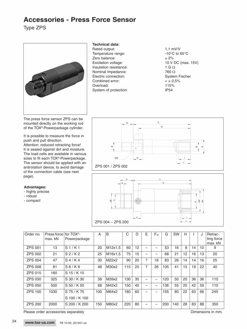
Accessories - Press Force SensorType ZPS
The press force sensor ZPS can bemounted directly on the working rodof the TOX®-Powerpackage cylinder.
It is possible to measure the force inpush and pull direction.Attention: reduced retracting force!It is sealed against dirt and moisture.The load cells are available in varioussizes to fit each TOX®-Powerpackage.The sensor should be applied with anantirotation device, to avoid damageof the connection cable (see nextpage).
Technical data:Rated output: 1,1 mV/VTemperature range: -10°C to 65°CZero balance: ± 2%Excitation voltage: 10 V DC (max. 15V)Insulation resistance: 1 G WNominal impedance: 760 WElectric connection: System FischerCombined error: < ± 0,5%Overload: 115%System of protection: IP54
Advantages:- highly precise- robust- compact
Please order accessories separately Dimensions in mm.
D
J
ØB
B SW
ØAF
g6
E G
C
H I
ZPS 004 – ZPS 200
C
G
D
BB
SW H I
J
A
ZPS 001 / ZPS 002
Order no. Press forcemax. kN
for TOX®-Powerpackage
A B C D E Fg6 G SW H I J Retrac-ting forcemax. kN
ZPS 001 13 S 1 / K 1 20 M12x1,5 60 12 – – 53 16 8 14 10 9
ZPS 002 21 S 2 / K 2 25 M16x1,5 75 15 – – 68 21 12 16 13 20
ZPS 004 47 S 4 / K 4 30 M22x2 90 20 7 18 83 26 14 14 16 25
ZPS 008 81 S 8 / K 8 48 M30x2 115 25 7 26 105 41 15 19 22 40
ZPS 015 160 S 15 / K 15
ZPS 030 325 S 30 / K 30 58 M39x2 130 35 – – 120 50 20 36 36 110
ZPS 050 500 S 50 / K 50 68 M42x2 150 40 – – 136 55 20 42 59 110
ZPS 100 1030 S 75 / K 75 100 M64x2 180 60 – – 155 85 22 63 66 245
S 100 / K 100
ZPS 200 2000 S 200 / K 200 150 M80x2 220 80 – – 200 140 28 83 88 350
25www.tox-us.comTB 10.00_201201.us
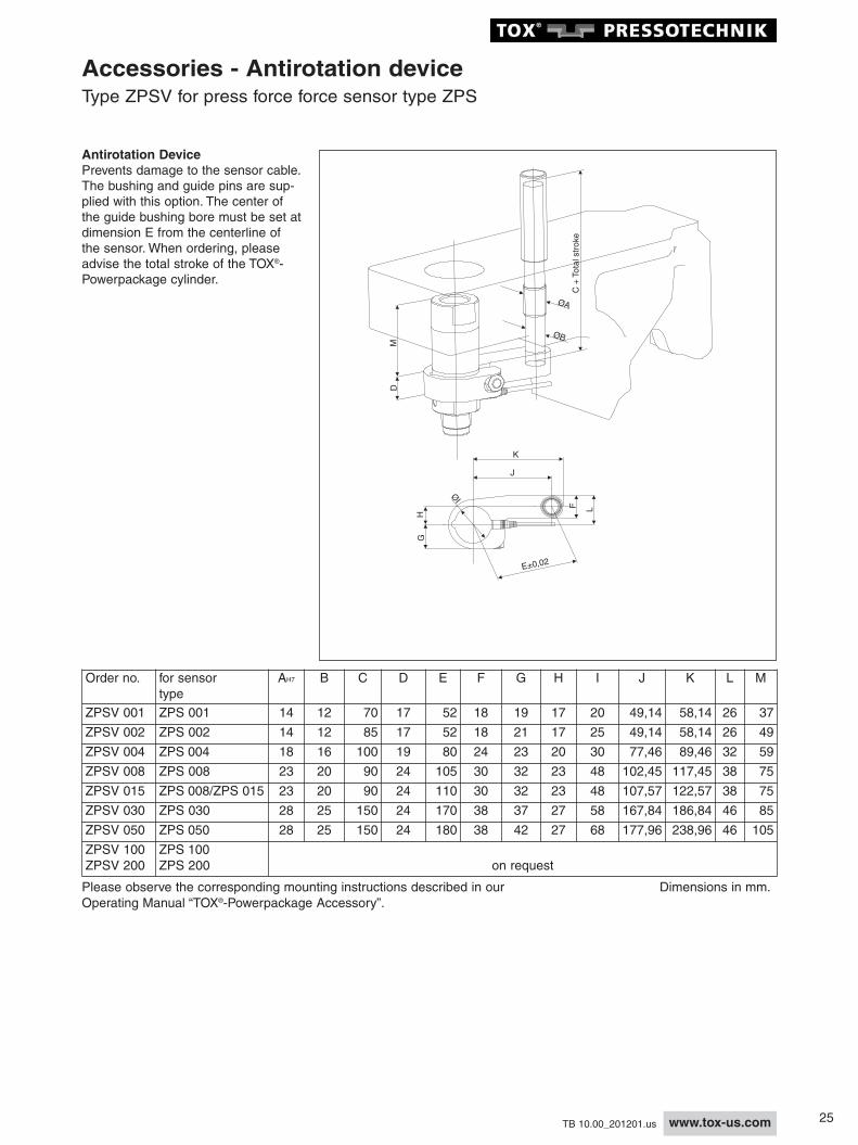
Accessories - Antirotation deviceType ZPSV for press force force sensor type ZPS
Antirotation DevicePrevents damage to the sensor cable.The bushing and guide pins are sup-plied with this option. The center ofthe guide bushing bore must be set atdimension E from the centerline ofthe sensor. When ordering, pleaseadvise the total stroke of the TOX®-Powerpackage cylinder.
D
ØA
ØB
C +
Tota
l str
oke
M
Please observe the corresponding mounting instructions described in ourOperating Manual “TOX®-Powerpackage Accessory”.
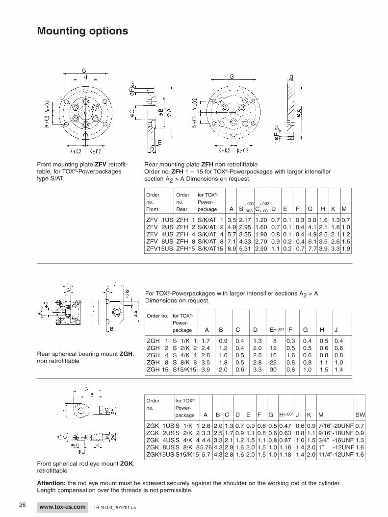
Front mounting plate ZFV retrofit-table, for TOX®-Powerpackagestype S/AT.
Rear mounting plate ZFH non retrofittableOrder no. ZFH 1 – 15 for TOX®-Powerpackages with larger intensifiersection A2 > A Dimensions on request.
Rear spherical bearing mount ZGH,non retrofittable
For TOX®-Powerpackages with larger intensifier sections A2 > ADimensions on request.
Front spherical rod eye mount ZGK,retrofittable
Attention: the rod eye mount must be screwed securely against the shoulder on the working rod of the cylinder.Length compensation over the threads is not permissible.
- ZMP - 001.002Mounting plate for attachment to theservice side of TOX®-Powerpackage
Accessories
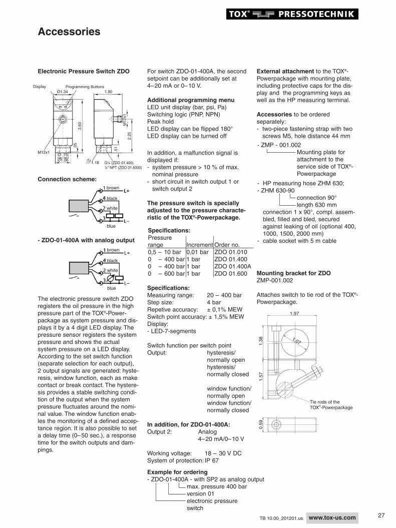
Electronic Pressure Switch ZDO
Connection scheme:
The electronic pressure switch ZDOregisters the oil pressure in the highpressure part of the TOX®-Power-package as system pressure and dis-plays it by a 4 digit LED display. Thepressure sensor registers the systempressure and shows the actualsystem pressure on a LED display.According to the set switch function(separate selection for each output),2 output signals are generated: hyste-resis, window function, each as makecontact or break contact. The hystere-sis provides a stable switching condi-tion of the output when the systempressure fluctuates around the nomi-nal value. The window function enab-les the monitoring of a defined accep-tance region. It is also possible to seta delay time (0–50 sec.), a responsetime for the switch outputs and dam-pings.
In addition, a malfunction signal isdisplayed if:- system pressure > 10 % of max. nominal pressure
- short circuit in switch output 1 or switch output 2
The pressure switch is speciallyadjusted to the pressure characte-ristic of the TOX®-Powerpackage.
Working voltage: 18 – 30 V DCSystem of protection: IP 67
External attachment to the TOX®-Powerpackage with mounting plate,including protective caps for the dis-play and the programming keys aswell as the HP measuring terminal.
Accessories to be orderedseparately:- two-piece fastening strap with two screws M5, hole distance 44 mm
- HP measuring hose ZHM 630;- ZHM 630-90
connection 90°length 630 mm
connection 1 x 90°, compl. assem-bled, filled and bled, secured against leaking of oil (optional 400, 1000, 1500, 2000 mm)
- cable socket with 5 m cable
Example for ordering- ZDO-01-400A - with SP2 as analog output
Attaches switch to tie rod of the TOX®-Powerpackage.
1.97
Tie rods of theTOX -Powerpackage®
1.07
0.59
1.57
1.38
For switch ZDO-01-400A, the secondsetpoint can be additionally set at4–20 mA or 0–10 V.
Additional programming menuLED unit display (bar, psi, Pa)Switching logic (PNP, NPN)Peak holdLED display can be flipped 180°LED display can be turned off
brown
white
blue
black
- ZDO-01-400A with analog output
Specifications:Pressurerange Increment Order no.0,5 – 10 bar 0,01 bar ZDO 01.0100 – 400 bar 1 bar ZDO 01.4000 – 400 bar 1 bar ZDO 01.400A0 – 600 bar 1 bar ZDO 01.600
Display Programming ButtonsØ1.34
3.60
.05
1.90
Ø .75
1.18
M12x1
G¼ (ZDO 01.400)¼” NPT (ZDO 01.6000)
M12x1
.51
2.25
Ø1.06
brown
white
blue
black
28 www.tox-us.com TB 10.00_201201.us
Accessories
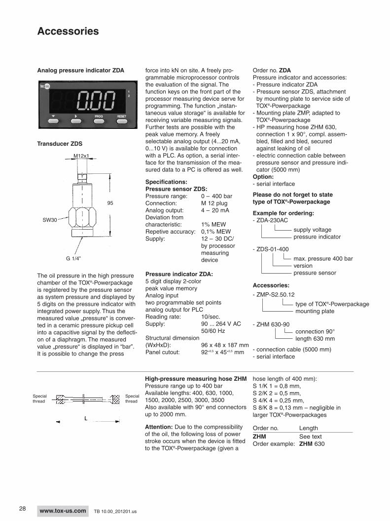
Analog pressure indicator ZDA
SW30
M12x1
G 1/4”
95
force into kN on site. A freely pro-grammable microprocessor controlsthe evaluation of the signal. Thefunction keys on the front part of theprocessor measuring device serve forprogramming. The function „instan-taneous value storage“ is available forreceiving variable measuring signals.Further tests are possible with thepeak value memory. A freelyselectable analog output (4...20 mA,0...10 V) is available for connectionwith a PLC. As option, a serial inter-face for the transmission of the mea-sured data to a PC is offered as well.
The oil pressure in the high pressurechamber of the TOX®-Powerpackageis registered by the pressure sensoras system pressure and displayed by5 digits on the pressure indicator withintegrated power supply. Thus themeasured value „pressure“ is conver-ted in a ceramic pressure pickup cellinto a capacitive signal by the deflecti-on of a diaphragm. The measuredvalue „pressure“ is displayed in “bar”.It is possible to change the press
Pressure indicator ZDA:5 digit display 2-colorpeak value memoryAnalog inputtwo programmable set pointsanalog output for PLCReading rate: 10/sec.Supply: 90 ... 264 V AC
50/60 HzStructural dimension(WxHxD): 96 x 48 x 187 mmPanel cutout: 92+0,5 x 45+0,5 mm
Example for ordering:- ZDA-230AC
supply voltagepressure indicator
- ZDS-01-400
max. pressure 400 barversionpressure sensor
- ZMP-S2.50.12
type of TOX®-Powerpackagemounting plate
- ZHM 630-90connection 90°length 630 mm
- connection cable (5000 mm)- serial interface
Order no. ZDAPressure indicator and accessories: - Pressure indicator ZDA- Pressure sensor ZDS, attachmentby mounting plate to service side ofTOX®-Powerpackage- Mounting plate ZMP, adapted toTOX®-Powerpackage- HP measuring hose ZHM 630,connection 1 x 90°, compl. assem-bled, filled and bled, securedagainst leaking of oil - electric connection cable betweenpressure sensor and pressure indi-cator (5000 mm)
Option:- serial interface
Please do not forget to statetype of TOX®-Powerpackage
Accessories:
High-pressure measuring hose ZHMPressure range up to 400 barAvailable lengths: 400, 630, 1000,1500, 2000, 2500, 3000, 3500Also available with 90° end connectorsup to 2000 mm.
Attention: Due to the compressibilityof the oil, the following loss of powerstroke occurs when the device is fittedto the TOX®-Powerpackage (given a
hose length of 400 mm):S 1/K 1 = 0,8 mm, S 2/K 2 = 0,5 mm,S 4/K 4 = 0,25 mm, S 8/K 8 = 0,13 mm – negligible inlarger TOX®-Powerpackages
Order no. LengthZHM See textOrder example: ZHM 630
Specialthread
Specialthread
Transducer ZDS
29www.tox-us.comTB 10.00_201201.us
Accessories/Special Models
Oil pumpIt guarantees the optimum maintenan-ce concept and extended maintenan-ce intervals. For easy, air-free refillingand reduction of the oil volume of theTOX®-Powerpackage. Clear body andrefill hose allow easy monitoring of theoil level in the pump. Little operatoreffort required.
Pumping medium: hydraulic oil DIN51524 HL or HPL with 32 cStviscosity at 40° C.– Pump capacity: 9 ml/stroke– Container filling volume 0,3l– Max.permissible back pressure 10 bar– Hose length 800 mm
Order no.ZP 20.000
Oil level monitor ZUWhen the minimum oil level isreached, the indicator pin integratedin the TOX®-Powerpackage actuates aswitch (can be pneumatic or electric).Mounted via steel strip.Manual reset.Can be retrofitted to all TOX®-Powerpackages.
Type ZU 01 = floating contact set withstep function (open/close)Contact load rating 0 - 30 V DCConstant current 5 ACable length 2 m.
Type ZU 02 = 3/2-way valve with lok-king zero setting (make contact)Connecting thread M5
Type ZU 03 = as for ZU 02, but withquick connector
TOX®-Powerpackage for use in thefood industry ZLMAll TOX®-Powerpackages are availa-ble on request with food grade oil andgrease lubrication. Both lubricants arecertified according to USDA-H11 andare used wherever there is a chanceof occasional, technically unavoidablecontact between foodstuffs and lubri-cant.These TOX®-Powerpackages are usedin industrial food manufacturing, pro-cessing, filling and packaging machi-nes, as well as in the pharmaceuticaland cosmetics industry.
Order no.ZWS 01
Tool Set to Replace Seals ofTOX®-Powerpackage CylindersSpecial tools facilitate the removaland installation of seals.
The carrying case also containsinstructions and tips on the use ofthe tools.
30 www.tox-us.com TB 10.00_201201.us
Power bypass ZHD with hydraulicend position cushion in the returnstrokeA patented further development ofthe power bypass ZLB, the integra-ted hydraulic end position dampe-ning (non adjustable) provides opti-mum cushioning of the working rodat the end of the return stroke. Thisfeature is especially useful in appli-cations with heavy tooling weightand high cycle speeds. This resultsin longer tool life and reduced noiselevel of the TOX®-Powerpackage, evenon severe working conditions.
TOX®-Powerpackage cylindersS 4 – S 170, K 75 – K 170, AT 170and line-Q come standard equippedwith bypass and end position dam-pening.
TOX®-Powerpackage series AT 2 –AT 100 and K 2 – K 50 are availablewith ZHD on request.
Order no.K 4.100.10 - ZHD
hydraulic endposition damping
Order no. ofTOX®-Power-package
Buffering gap Bypass valve
Special Models
TOX®-Powerpackage with powerbypass ZLBIn the event of control errors, or in thecase of special applications (particu -larly punching operations), the strongacceleration of the working piston af -ter punching through the material maycause an underpressure in the high-pressure oil chamber of the TOX®-Powerpackage and so lead to mal-functions. Such an underpressure canbe pre vented with the patented, inte-grated power bypass system ZLB avai-lable for the TOX®-Powerpackage.
Order no.S 1.32.6 - ZLB
Powerbypass
Order no. ofTOX®-Power-package
Order no.S 1.32.6 - ZRO
Anti-rustversion
Order no. ofTOX®-Power-package
Anti-rust execution ZROAll TOX®-Powerpackages can be sup-plied with rust protection on request.All individual parts are either chromi-um-plated, galvanised or primed andpainted, whereby stainless steel is notgenerally used. These devices areparticularly suitable for use in the foodand packaging industries.
It is also possible to use the bypasssystem for the realization of longpower strokes. Thus the characteri-stics of operation will be: approachstroke - power stroke - approach stro-ke - power stroke or approach stroke -power stroke - power stroke etc.which will e.g. be necessary for themounting of bushes.
The speeds required for these opera-tions should be kept relatively low,however. Please contact us for moredetailed advice if you intend to useyour equipment for the above purpo-ses.
A further development of the ZLB,the bypass ZHD with hydraulic dam-pening is a standard feature on allTOX®-Powerpackage cylindersS 4 – S 170, K 75 – K 170 andline-Q (see below).
31www.tox-us.comTB 10.00_201201.us
Special Models
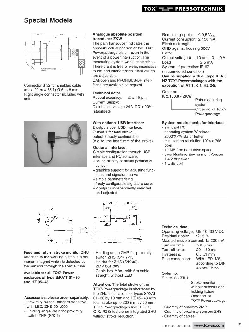
Analogue absolute position transducer ZKWThe path transducer indicates theabsolute actual position of the TOX®-Powerpackage piston, even in theevent of a power interruption. Themeasuring system works contactless.Therefore it is free of wear, insensitiveto dirt and interferences. Final valuesare adjustable.CANopen and PROFIBUS-DP inter-faces are available on request.
Technical data:Repeat accuracy: £ ± 10 µmCurrent Supply:Distribution voltage 24 V DC ± 20% (stabilized)
Remaining ripple: £ 0,5 VssCurrent consuption: £ 150 mAElectric strengthGND against housing 500V.Exits:Output voltage 0 ... 10 and 10 ... 0 VLoad £ 5 mASystem of protection: IP 67(in connected condition)Can be supplied with all type K, AT,HZ TOX®-Powerpackages with theexception of AT 1, K 1, HZ 2-5.
Order no.K 2.100.8 - ZKW
Path measuring systemOrder no. of TOX®-Powerpackage
Attention: The total stroke of theTOX®-Powerpackage is shortened bythe ZHU installation: for types S/K/AT01–30 by 10 mm and HZ 05–48 withtotal stroke up to 200 mm by 20 mm.TOX®-Powerpackages line-Q (Q-S, Q-K, RZS) feature an integrated ZHUwithout stroke reduction.
Feed and return stroke monitor ZHUAttached to the working piston is a per-manent magnet which is detected bythe sensors through the special tube.
Available for all TOX®-Power-packages of type S/K/AT 01–30and HZ 05–48.
- Quantity of brackets ZMP- Quantity of proximity sensors ZHS- Quantity of cables
.94” .94”
TOX -PowerpackageEnd cap
®
Ø70
Ø45
Sw46
74,5
33
49
123,5
- Holding angle ZMP for proximity switch ZHS (S/K 2-15)- Holder for ZHS (S/K 30),ZMP 001.003- Cable box M8x1 with 5m cable,straight, without LED
With optional USB interface:2 outputs over USB interface. Output 1 for total stroke; output 2 freely configurable (e.g. for the last 5 mm of the stroke).
Optional interface:Simple configuration through USBinterface and PC software:+online display of actual position of sensor+graphics support for adjusting func-tions and signature curve+simple parameterising+freely configurable signature curve+2 outputs independently selected and adjusted
System requirements for interface:- standard PC- operating system Windows 2000/XP/Vista or better- min. screen resolution 1024 x 768 pixel- 10 MB free hard drive space- Java Runtime Environment Version 1.4.2 or newer- 1 USB port
32 www.tox-us.com TB 10.00_201201.us
Mounting Instructions and Control Types
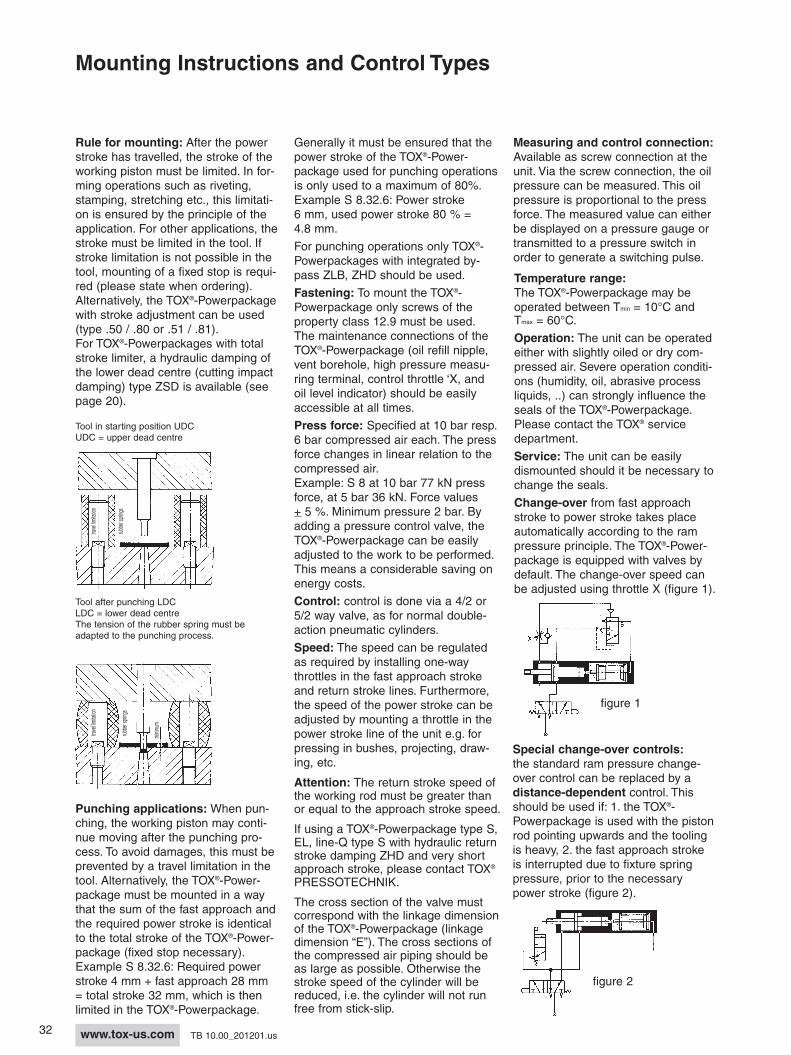
Tool in starting position UDCUDC = upper dead centre
Tool after punching LDCLDC = lower dead centreThe tension of the rubber spring must beadapted to the punching process.
Generally it must be ensured that thepower stroke of the TOX®-Power-package used for punching operationsis only used to a maximum of 80%.Example S 8.32.6: Power stroke6 mm, used power stroke 80 % =4.8 mm.
For punching operations only TOX®-Powerpackages with integrated by-pass ZLB, ZHD should be used.
Fastening: To mount the TOX®-Powerpackage only screws of the property class 12.9 must be used.The maintenance connections of theTOX®-Powerpackage (oil refill nipple,vent borehole, high pressure measu-ring terminal, control throttle ‘X, andoil level indicator) should be easilyaccessible at all times.
Press force: Specified at 10 bar resp.6 bar compressed air each. The pressforce changes in linear relation to thecompressed air. Example: S 8 at 10 bar 77 kN pressforce, at 5 bar 36 kN. Force values+ 5 %. Minimum pressure 2 bar. Byadding a pressure control valve, theTOX®-Powerpackage can be easilyadjusted to the work to be performed.This means a considerable saving onenergy costs.
Control: control is done via a 4/2 or5/2 way valve, as for normal double-action pneumatic cylinders.
Speed: The speed can be regulatedas required by installing one-waythrottles in the fast approach strokeand return stroke lines. Furthermore,the speed of the power stroke can beadjusted by mounting a throttle in thepower stroke line of the unit e.g. forpressing in bushes, projecting, draw-ing, etc.
Attention: The return stroke speed ofthe working rod must be greater thanor equal to the approach stroke speed.
If using a TOX®-Powerpackage type S,EL, line-Q type S with hydraulic returnstroke damping ZHD and very shortapproach stroke, please contact TOX®
PRESSOTECHNIK.
The cross section of the valve mustcorrespond with the linkage dimensionof the TOX®-Powerpackage (linkagedimension “E”). The cross sections ofthe compressed air piping should beas large as possible. Otherwise thestroke speed of the cylinder will bereduced, i.e. the cylinder will not runfree from stick-slip.
Special change-over controls:the standard ram pressure change-over control can be replaced by a distance-dependent control. Thisshould be used if: 1. the TOX®-Powerpackage is used with the pistonrod pointing upwards and the toolingis heavy, 2. the fast approach strokeis interrupted due to fixture springpressure, prior to the necessarypower stroke (figure 2).
travel limitation
rubber springs
travel limitation
minim
um
rubber springs
figure 1
figure 2
Measuring and control connec tion:Available as screw connection at theunit. Via the screw connection, the oilpressure can be measured. This oilpressure is proportional to the pressforce. The measured value can eitherbe displayed on a pressure gauge ortransmitted to a pressure switch inorder to generate a switching pulse.
Temperature range:The TOX®-Powerpackage may beoperated between Tmin = 10°C andTmax = 60°C.
Operation: The unit can be operatedeither with slightly oiled or dry com-pressed air. Severe operation conditi-ons (humidity, oil, abrasive processliquids, ..) can strongly influence theseals of the TOX®-Powerpackage.Please contact the TOX® servicedepartment.
Service: The unit can be easilydismounted should it be necessary tochange the seals.
Change-over from fast approachstroke to power stroke takes placeautomatically according to the rampressure principle. The TOX®-Power-package is equipped with valves bydefault. The change-over speed canbe adjusted using throttle X (figure 1).
Rule for mounting: After the powerstroke has travelled, the stroke of theworking piston must be limited. In for-ming operations such as riveting,stamping, stretching etc., this limitati-on is ensured by the principle of theapplication. For other applications, thestroke must be limited in the tool. Ifstroke limitation is not possible in thetool, mounting of a fixed stop is requi-red (please state when ordering).Alternatively, the TOX®-Powerpackagewith stroke adjustment can be used(type .50 / .80 or .51 / .81).For TOX®-Powerpackages with totalstroke limiter, a hydraulic damping ofthe lower dead centre (cutting impactdamping) type ZSD is available (seepage 20).
Punching applications: When pun-ching, the working piston may conti-nue moving after the punching pro-cess. To avoid damages, this must beprevented by a travel limitation in thetool. Alternatively, the TOX®-Power-package must be mounted in a waythat the sum of the fast approach andthe required power stroke is identicalto the total stroke of the TOX®-Power-package (fixed stop necessary).Example S 8.32.6: Required powerstroke 4 mm + fast approach 28 mm= total stroke 32 mm, which is thenlimited in the TOX®-Powerpackage.
33www.tox-us.comTB 10.00_201201.us
We present the system comparisonPress forces from .2 to 200 tonsTotal strokes up to 400 mm, power strokes up to 80 mm
5) Capacity
The TOX®-Powerpackage behaveslike a pneumatic cylinder in its opera-tion and cycle speeds. Despite itscompact dimensions, it delivers thehard work and high forces associatedwith hydraulic systems, however, with-out the need for an expensive hydrau-lic unit. The TOX®-Powerpackage pro-vides a clean, quiet and reliable ope-ration.
2) Warranty
The standard TOX®-Powerpackagetype S and type K are guaranteed for10 million cycles, or one year, regard-less of the number of working shiftsor hours.
3) Energy consumption
The TOX®-Powerpackage provides upto 90% energy savings compared topneumatic or hydraulic systems.Energy is used only when needed,namely for the power stroke, barelyany for the fast approach and returnstroke.
6) Environment
The TOX®-Powerpackage provides anextremely low noise level due to thehydraulic end position damping in thereturn stroke. In addition, a lowexhaust noise and reduced air con-sumption. No oil disposal or oil conta-mination from leakage, no generationof noise such as produced by a con-stantly running hydraulic pump.
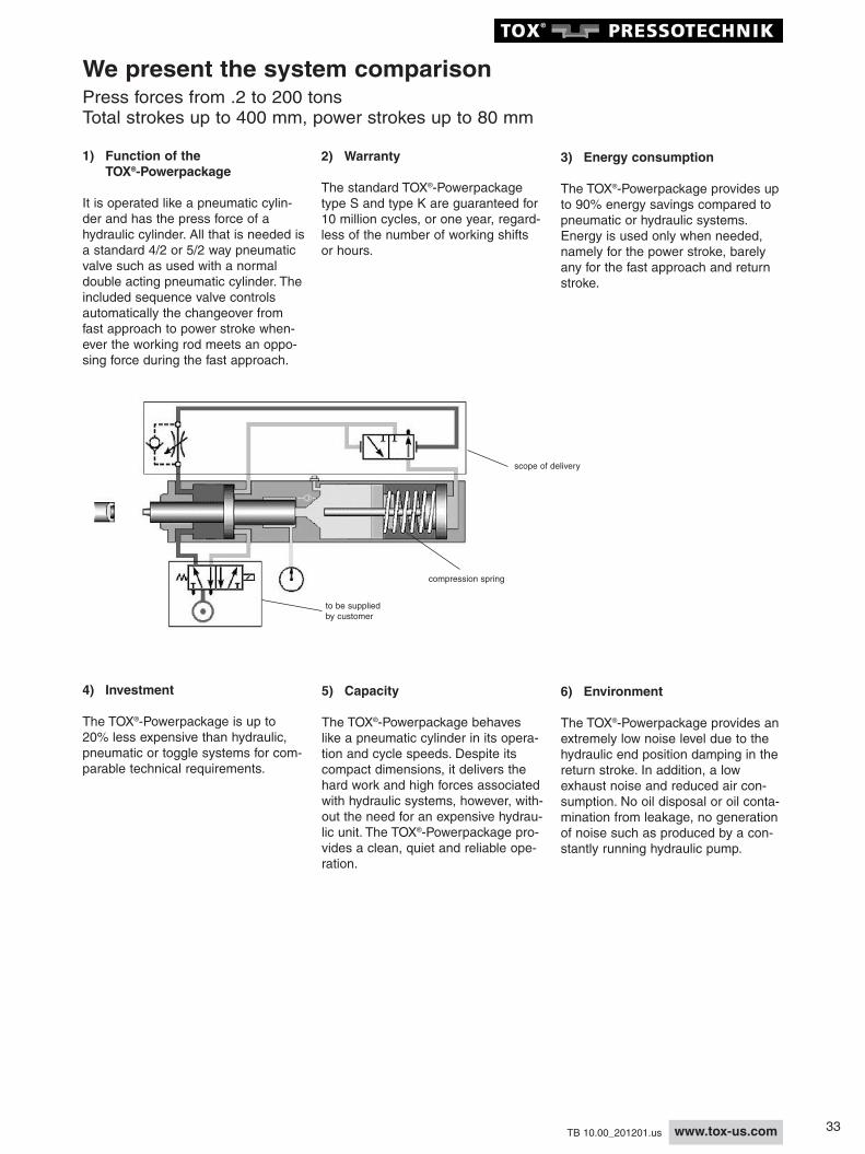
1) Function of the TOX®-Powerpackage
It is operated like a pneumatic cylin-der and has the press force of ahydraulic cylinder. All that is needed isa standard 4/2 or 5/2 way pneumaticvalve such as used with a normaldouble acting pneumatic cylinder. Theincluded sequence valve controlsautomatically the changeover fromfast approach to power stroke when-ever the working rod meets an oppo-sing force during the fast approach.
4) Investment
The TOX®-Powerpackage is up to20% less expensive than hydraulic,pneumatic or toggle systems for com-parable technical requirements.
to be suppliedby customer
scope of delivery
compression spring
34 www.tox-us.com TB 10.00_201201.us
- The patented power bypass pro-tects the oil system from negative pressure, which can be generated in applications, such as punching, shearing, etc. or high cycle speeds. The power bypass is the basic requi-rement for trouble-free operation of pneumo-hydraulic systems in such applications.
- Patented, hydraulic end positiondamping in the DC for a quiet andmaterial-protecting operation
If short fast approach strokes arerequired, please contact TOX®
PRESSOTECHNIK. This is a stan-dard feature for all TOX®-Power-packages type S 4 – S 170,K 75 – K 170 and line-Q.
- The ingenious double function of the mechanic spring entails energysavings. No additional air is neededfor the return stroke of the transdu-cer and the automatic preroading ofthe feed piston allows for any moun-ting position of the cylinder. It is a matter of course that these elementsare also included in the 10 million stroke guarantee. Because of the spring, no additional air connectionon the unit is required.
- Sealing system: The use of longlifeseals and a continuous developmentare guaranteed with the TOX®-Powerpackage, the evidence in the10 million strokes guarantee.
- Patented absolute air/oil separati-on is a prerequisite for a troublefreeoperation over a long period of time. A ring groove connected to theatmosphere avoids the "carry-over" of air into the oil.
- The double-bearing arrangementof the working rod ensures an extra-ordinary good guidance.
7) Technology of the TOX®-Powerpackage
8) Service maintenance
TOX® companies and agents throug-hout the world are at your service. Ifneeded e.g., in case of a service, areplacement cylinder can be providedof a nominal charge, during the ser-vice period.
- Stroke monitor type ZHU and analo-goue absolute position framducertype ZKW to determine the preciseposition of the working rod.
- Special types and accessoriesWe will find a solution for all your requirements and problems.
Transducer
Air
Air
Oil
work area
patented
air/oil separation
with air spring
damping slot bypass valve
35www.tox-us.comTB 10.00_201201.us
TOX®-PowerpackageAir pressure/oil pressure/press forceTOX®-Powerpackage type S, K
Oil pressure - press force table for 10 bar
Oil pressure - press force table for 6 bar
Tolerance ± 5%
Tolerance ± 5%
Specifications only apply to TOX®-Powerpackages of measure A = A2, all other types on request.
Specifications only apply to TOX®-Powerpackages of measure A = A2, all other types on request.
Air consumption type S and Kseries 10 bar (145 psi)
At 70 % effective force, fast approach stroke 38 mmand 10 % of the fast approach stroke force
Operation at 6 bar (87 psi) air pressure.
Stroke frequency of types S and Kseries 10 bar (145 psi)
At 70 % effective force, fast approach stroke 38 mmand 10 % use of the fast approach stroke force
Operation at 6 bar (87 psi) air pressure.Max. stroke frequency requires ZLB or ZHD.