WMH-188/288 SERIAL INDEX GENERAL DESCRIPTION 1 BLOCK DIAGRAM OF MAJOR COMPONENTS 2 PLAY INSTRUCTIONS 3 MAIN PC BOARD WIRING DIAGRAM 4 DIP SWITCH SETTINGS 6 SETTING CLAW STRENGTH 7 BOARD SELECTABLE VALUES OPTIONS 8 TEST MODES & ERROR CODES 9 CLAW CORD WINDING INSTRUCTIONS 11 TROUBLE SHOOTING 12 GANTRY & ASSEMBLY I 15 GANTRY & ASSEMBLY II 16 SCHEMATICS 17
GENERAL DESCRIPTION
Overview:
Your Toy Soldier consists of two main systems the hardware and the firmware.
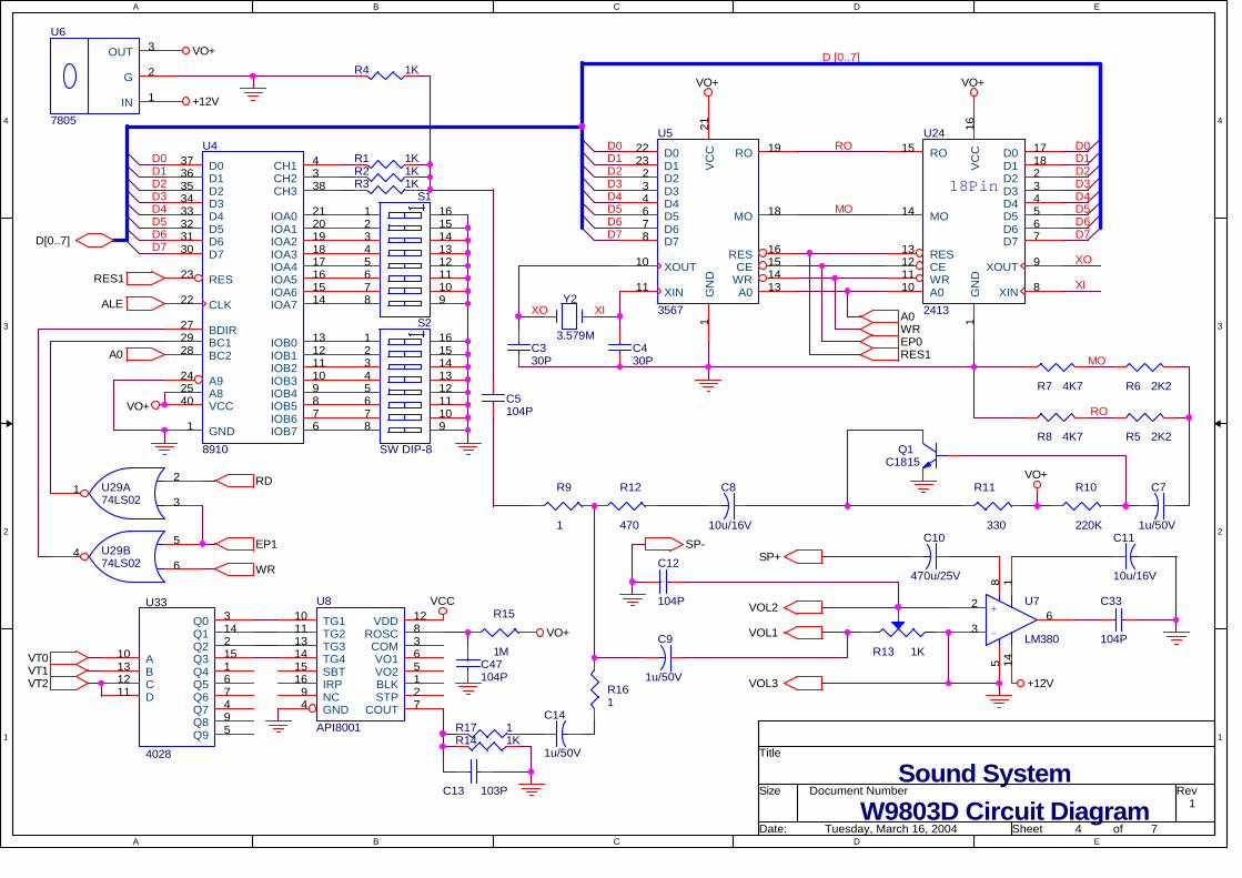
The firmware is located in U3 a 27C512 EPROM and is processed by U1 a (78C32C-40) 8-BIT micro controller. The voice sound bytes are stored on U8 (API8108A). The games music is controlled by the processor and is generated by U4 (JFC95101) and U5 (YM2413) stores music files. The games main logic board will retain credits accumulated even after power is removed.
The hardware consists of the crane gantry, the control panel, the coin mechanism (and/or bill acceptor), payout sensors and Lighting systems.
The gantry consists of a sturdy metal frame, which rides steel rails built into the cabinet and is driven by the front/back motor located in the left side of the gantry structure when you are facing the machine. The up/down and left/right motors are contained in the carriage that rides the gantry’s rails.
The control panel consists of either a joystick and drop button, or control buttons, and the digital display. Joystick control is intuitive, and the button-equipped models are clearly labeled. The display shows at various times, accumulated credits, game time remaining, and diagnostic information.
The coin door can either support two (coin comparator type) coin mechanisms, or one comparator and a bill acceptor. The crane harness has wiring provided to install a bill acceptor, and a plate to neatly cover the area where the coin comparator was removed.
The prize chute is equipped with photoelectric sensors and reflectors to keep a tally of the number of prizes dispensed.
A fluorescent light fixture in the ceiling of the unit provides lighting for the prize floor, and the marquee. Rope lights flash down the two forward corners also drawing the attention of passers by.
Behind the coin door you will find on the left the speaker, a voltmeter, and three adjustment knobs, VR1 VR2 and VOLUME. On the right a brass pendulum senses if the machine is shaken or moved suddenly, causing the main board to give the warning, “Don’t Shake The Machine!”
These components combine to give you a reliable, sturdy, and fun addition to your redemption enterprise, the Toy Soldier.
1
Block Diagram of Major Components
SWITCHES
V
SPEAKER
VOLUME CONTROL
CONTROL PANEL
ACCOUNTING METERS
CLAW POTENTIOMETERS
GANTRY
PUSHER PLATE
MOTOR & SWITCHES
DOOR FLAP
MOTOR &
DOOR FLAP CONTROLLER
POWER SUPPLY
MAIN PCB
FLUORESCENT LIGHTS
ROPE LIGHTS
ROPE LIGHT CONTROLLER
AC POWER SWITCH
2
PLAY INSTRUCTIONS: 1. Open the coin door, on the top of the coin comparator you will see a black plastic module
with a blue sticker on the side held by a retaining spring. You have to insert a sample of the coin/token that you are going to use in the slot of this module. After inserting the coin/ token the comparator will accept this type of coin/token.
2. Once the comparator is set up, insert coins, each coin makes the machine give the voice prompt “way to go “ and advances the coin 1 meter one increment. After the proper number of credits is reached (default setting is 2 coins/tokens per play.) The game will enter play mode with the voice prompt “good luck.” The display will show the credits accumulated.
3. The joystick is intuitive, moving the crane gantry and carriage in the direction that it is pushed, once the claw is positioned the drop button allows the claw to lower, the drop button is inactive until the joystick has been used to move the gantry or carriage. If the machine is equipped with buttons they are used as follows: BACK button moves the gantry backward and the RIGHT button moves the carriage to the right for positioning the claw, pushing either button a second time causes the claw to lower or it will lower when game time expires.
4. Once the limit switches in the carriage detect that the claw has reached the bottom of its descent the claw will automatically close and wind up. During this phase the claw strength is determined by the main PCB and the setting of VR1.
5. When the claw returns to the carriage, the second stage of claw power is engaged which is controlled by VR2 and the main PCB. The gantry and carriage then return to the “home” position and release any prize that has been won.
6. If a prize been won, the optical sensors will be triggered, a voice says “congratulations” and the prize meter will register the win. The prize can then be retrieved through the flap door.
3
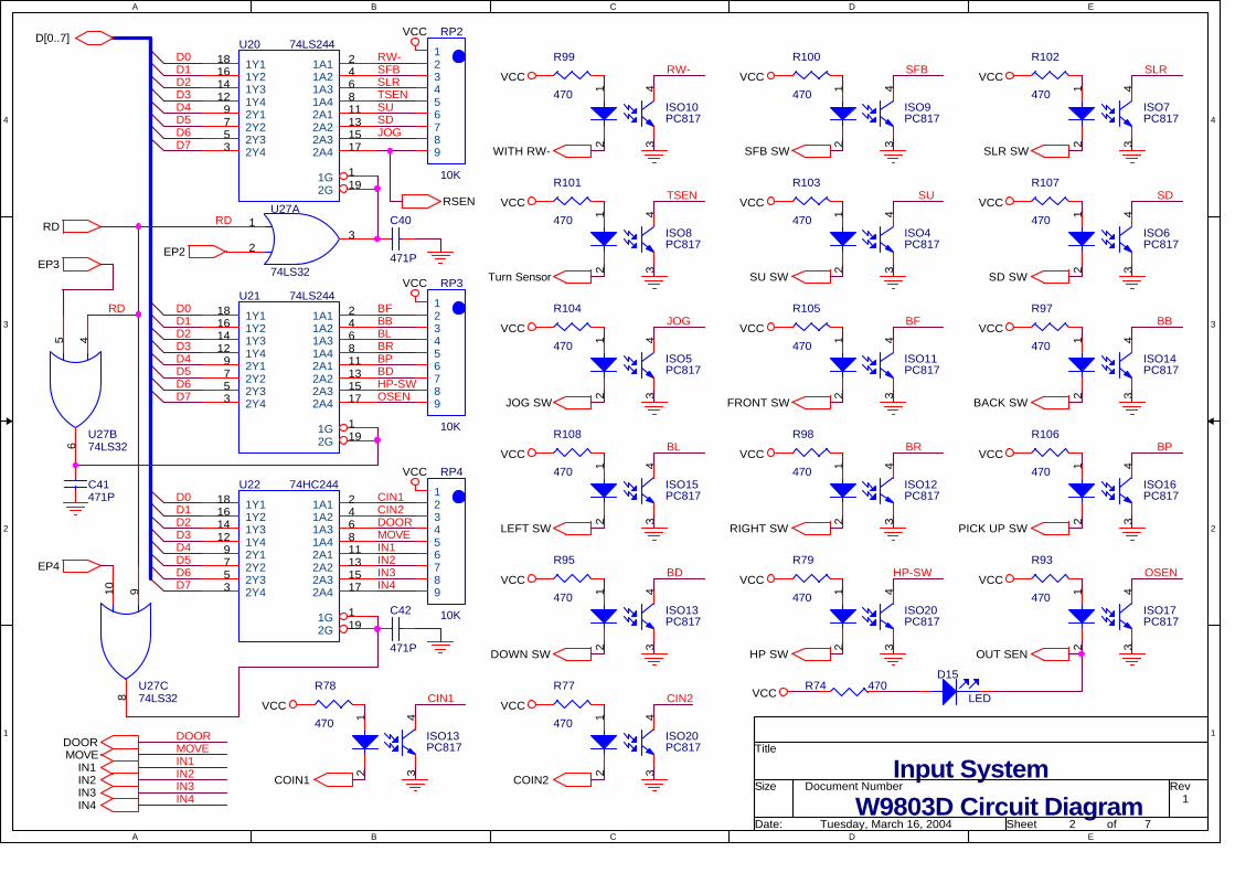
WMH-188/288 series Main PCB Wiring diagram
1 1 1 1 1 1 1
J10 J11 J8 J7 J2 J3 J1 JP4 1
J12 1
J13 DIP SWITCH 2 DIP SWITCH 1 J6 J5 JP1 J4 1 1 1
RL6
RL5
RL4
RL7
RL8
RL9
RL10
EPROM U3
J7 COLOR CONNECTION
1 Rd/Wht +12 VDC 2 Or/Wht Coin 1 meter 3 Ye/Grn Coin 2 Meter 4 Grn/Wht Prize Meter 5 Blu/Wht Ticket Meter
J1 COLOR CONNECTION 1 Black Ground 2 Brown Joystick Front SW (N.O.) 3 Red Joystick Back SW (N.O.) 4 Orange Joystick Right SW (N.O.) 5 Yellow Joystick Left SW (N.O.) 6 Green Descend SW (N.O.) 7 Blue Running SW (N.O.) 8 Black Ground 9 Grey Descend (RIGHT) Button Light 10 White Running (FRONT) Button Light
J8 COLOR CONNECTION 1 Brown Tilt Sw (N.O.) 2 Purple Pusher Sw (N.O.)3 Black Ground 4 Black Coin Sw. 1 Gnd. 5 Wht/Grn Coin Sw. 1 Sig. 6 Red Coin Sw. 1 +12V 7 Red Coin Sw. 2 +12V 8 Wht/Blu Coin Sw. 2 Sig. 9 Black Coin Sw. 2 Gnd. 10 Black Test Coin Sw Com.11 Grn/Wht Test Coin Sw. (N.O.)12 White NOT USED 13 Red NOT USED 14 Red +12 VDC Pusher Motor15 Grn/Wht Bill Acceptor Inhibit16 Black Ground 17 Coin Inhibit Output Pos.18 Green Coin Inhibit Output Neg.
J3 COLOR CONNECTION 1 Black 2 Green 3 Yellow 4 Orange 5 Red 6 Brown 7 8 Blue
Super Card Connections
4
JP1 COLOR CONNECTION1 Black Ground 2 Black Ground 3 Black Ground 4 Yellow +5 VDC In 5 Yellow +5 VDC In 6 Red +12 VDC In 7 Red +12 VDC In 8 Orange +24 VDC In 9 Orange +24 VDC In 10 Violet +48 VDC In
J11 COLOR CONNECTION 1 Black to
Orange IN 2
2 Brown to Red IN4
3 Red to Brown EO 4
4 5 Orange
to Black EO 5
JP 3 W9833 B
oard
J10 COLOR CONNECTION 1 Blue Prize Sensor Ground 2 Grey Prize Sensor Signal 3 Brown Prize Sensor +12VDC
JP4 RESERVED J12 COLOR CONNECTION 1 2 3 OUT 4 GROUND 5 IN 6 GROUND 7 OUT 8
RE
SER
VE
D
J4 COLOR CONNECTION 1 Brn/Org Front/Back Motor + 2 Rd/Blk Left Right Motor - 3 Org/Blk Up Down Motor - 4 White Claw Coil 5 6 Blu/Org Front/back limit sw. 7 8 Vio/Yell Left/Right limit sw. 9 Pink Claw up limit sw. 10 Black Claw Down limit sw. 11 12 13 14 Brown Front/Back Motor - 15 Red Left Right Motor + 16 Orange Up Down Motor + 17 Yellow Claw Coil 18 19 Blue Front/back limit sw. Common 20 Violet Left/Right limit sw. Common 21 Grey Claw Up/Dn. Limit sw.’s Common 22 23 24 25
J13 COLOR CONNECTION 1 CLOCK 2 RESERVED GROUND J6 COLOR CONNECTION 1 White Volume Control Pin 1 2 Red Volume Control Pin 2 3 Black Volume Control Pin 3 4 Black Speaker (-) 5 Violet Speaker (+) J5 COLOR CONNECTION 1 Red Pot. VR1 Signal 2 Orange Pot. VR1 Common 3 Yellow Pot. VR2 Signal 4 Green Pot. VR2 Common 5 Pink Claw Voltmeter (+) 6 Black Claw Voltmeter (-)
5
DIP SWITCH SETTINGS DIP SW 1 1 2 3 4 5 6 7 8
NOT USED OFF Lower, Then release ON Claw Drop Position Release at top OFF Installed Super Card Not Installed OFF On ON Catch in Air Off OFF Opposite of Home ON Prize Chute Position
Front to Rear Same as Home OFF RANDOM ON Highest Power
to Claw FIXED OFF ON Plays every 5min. (claw doesn’t close) ON Attract Mode
Demo Game OFF OFF Installed ON Motorized Exit
Door Function Not Installed OFF
DIP SW 2 1 2 3 4 5 6 7 8 6 ON ON 4 OFF ON 2 ON OFF Coins/Tokens Per Play
1 OFF OFF 4 ON ON 3 OFF ON 2 ON OFF Bill Acceptor Pulses per Play
1 OFF OFF ON ON Attract Mode Music OFF OFF ON Credit deduction on win* ON Play Until Win Function OFF Credit deduction every game OFF YES ON Editable Menu Settings NO OFF
Button ON Control Panel Type Joystick OFF* In order for the play until win function to operate the crane must be equipped with a prize sensor.
Note: HOME and EXIT Positions
6Control Panel
LEFT REAR RIGHT REAR LEFT FRONT RIGHT FRONT
SETTING CLAW STRENGTH – The voltage level going to the claw coil can be adjusted with two
potentiometers VR1 & VR2. VR1 controls the power going to the claw during the time that the claw is being retracted to the carriage. VR2 controls the power going to the claw as the gantry returns the claw to the “Home” position. Specific claw strength settings are very dependent on the prizes that are stocked in the crane. It is recommended that the claws lifting ability be tested with a variety of the prizes being used.
The Voltage levels being sent to the claw can be easily adjusted using the following procedure:
1 Adjust the switch on the rear of either coin comparator to the NORMALLY CLOSED position. (During normal operation the switch is set to NORMALLY OPEN.) Then power up the crane. The Digital display should show (CO). Reset the switch on the rear of the coin comparator to the NORMALLY OPEN position.
2 Push the joystick BACK and HOLD, the voltmeter above VR1 & VR2 will show the voltage that VR1 is currently set to. Turn VR1 potentiometer until the desired voltage is displayed on the voltmeter. The display shows (C1)
3 Move the joystick to the RIGHT and HOLD, the voltmeter above VR1 & VR2 will show the voltage that VR2 is currently set to. Turn VR2 potentiometer until the desired voltage is displayed on the voltmeter. The display shows (C2)
4 Pull the joystick FRONT and HOLD, the voltmeter above VR1 & VR2 will show the maximum voltage that can be sent to the claw. The display shows (C3) *
5 Turn the machine off and then back on to reenter normal operation.
* The Voltmeter supplied in the crane is for reference purposes only, please use calibrated test equipment for troubleshooting.
7
Board Selectable Values Options
With the machine off, switch pole 7 of DIP switch 2 to the ON position. Power up the unit and the
displays should show a blinking (00). Your are now ready to proceed with set up. Momentarily moving the joystick to the BACK or LEFT increases the right (one’s) digit by one increment (1,2,3…), moving it momentarily to the RIGHT or FRONT increases the left (ten’s) digit one increment (10,20,30…). When the display matches the option number that you wish to modify press the DESCEND button, the display will stop flashing and show the value that the selected option is presently set to. You may use the joystick as described above to modify the value of the selected option. When you have modified the option to your desired value press DESCEND again, you will hear a double “beep” and the display will return to its flashing mode. You can either modify additional options or shut down the machine and return DIP switch 2 pole 7 to OFF and power up again to return to normal operation.
ITEM* SECTION DEFAULT VALUE
NOTES
00 Welcome to set up - 01 Tickets awarded for coin insertion 0 02 Tickets awarded for bill insertion 0 07 Tickets awarded if prize is won 0 08 Mercy Tickets 0 09 The number of games that the machine will treat as
a “group” for claw strength award purposes. 10 Setting a value of “0” sets the “group” size to 256
10 Game Play time (Seconds) 50 Inputting a value less than 5 will give 5 seconds.
* Values other than those shown in this table may be selectable from the set up menu; changing values for items not shown may affect machine reliability and operation. †If a number less than 11 is set for item 15 the following values will result:
Test Modes AUTOPLAY- This will put the gantry through its paces assuring the operation of all gantry motors and
limit switches. Either push the joystick to the BACK & RIGHT Position or press the BACK & RIGHT buttons and then turn machine on. The crane will automatically proceed through the following steps and repeat the sequence after completion.
DISPLAY ACTION
9 Gantry goes to home position* 2 Gantry Carriage runs to RIGHT limit 3 Gantry Carriage runs to BACK limit 4 Gantry Carriage runs to LEFT limit 5 Gantry Carriage runs to FRONT limit 6 Gantry Centers and Drops Claw, 8 Claw Closes and Lifts
*While at the home position the claw will close momentarily. SYSTEM CHECKS- To perform the following tests first turn the unit off, then set one of the coin
comparator switches to normally closed, and the bill acceptor credit signal line must be jumped to ground. CAUTION MUST BE USED COMPLETING THIS STEP, BE SURE THAT THE MACHINE IS UNPLUGGED, PINS 6 AND 4 OF THE BILL ACCEPTOR INTERFACE CONNECTOR CARRY 120VAC, DAMAGE OR INJURY CAN RESULT FROM CONTACT WITH THESE CONNECTIONS.
The credit signal line (White/Blue) is pin 7 on the bill acceptor interface connector. Pins 2,8,and 9 are ground. Jump pin 7 to pin 2,8, or 9. After the coin comparator switch is set to normally closed and the jumper has been properly set, plug the unit in and turn the power on. After the machine initializes the display will show (CC) to show that it is in test mode. The coin comparator switch can now be returned to normally open and the jumper CAREFULLY removed from the bill acceptor interface harness.
(Looking into plug)
The tests are selected with DIP switch 2 the values covered by the test can be scrolled through with the DESCEND button. After testing is completed be sure to return all switch poles to their operating settings.
DIP
SW 2 ITEM Description
1 Display Both display digits light single segments in step followed by each digit blinking all segments, one’s digit first, then ten’s digit.
2 DIP switches Each pole on each DIP switches light a segment of the digital display, with the eighth pole causing all segments of the display to blink. Dip switch 1 is displayed on the right digit and DIP switch 2 on the left digit.
3 NOT USED NOT USED 4 YM2413 Pressing any button steps through the music files. 5 API8108A Pressing any button steps through the voice files 6 JFC95101 Pressing any button steps through the music and sound effects files
7 CLEAR RECORD Digital display shows (CL) pressing any button clears the record of values stored on the board to be reset to zero.
8 ENTER VALUES Digital display shows (Ld) flashing, when the flashing stops values on the board are stored in memory.
9
CLAW STRENGTH With the unit off set one of the switches on the rear of either coin comparator to normally closed and
then power up the unit. The digital display will show (CO). The comparator switch can be returned to normally open. Follow the table below to check voltages going to the claw.
JOYSTICK POSITION ITEM TESTED DIGITAL DISPLAY
PUSH BACK VR1 C1 PUSH RIGHT VR2 C2 PULL FRONT CLAW Voltage (MAX) C3
GANTRY
The bill acceptor credit signal line must be jumped to ground. CAUTION MUST BE USED COMPLETING THIS STEP, BE SURE THAT THE MACHINE IS UNPLUGGED, PINS 6 AND 4 OF THE BILL ACCEPTOR INTERFACE CONNECTOR CARRY 120VAC, DAMAGE OR INJURY CAN RESULT FROM CONTACT WITH THESE CONNECTIONS. The credit signal line (White/Blue) is pin 7 on the bill acceptor interface connector. Pins 2,8,and 9 are ground. Jump pin 7 to pin 2,8, or 9.
JOYSTICK POSITION ACTION DIGITAL DISPLAY
PULL FRONT Claw Lowers a3 PUSH BACK Claw Raises a4 DESCEND BUTTON + JOYSTICK RIGHT
Carriage moves right b1
DESCEND BUTTON + JOYSTICK LEFT
Carriage moves left b2
DESCEND BUTTON + JOYSTICK BACK
Gantry moves back b3
DESCEND BUTTON + JOYSTICK FRONT
Gantry moves forward b4
ERROR CODES
ERROR CODE EXPLANATION E0 CPU bit checksum error E1 Gantry not connected or stop up switch not operational. E6 Flap door motor or control board malfunction E9 Accounting meter malfunction.
10
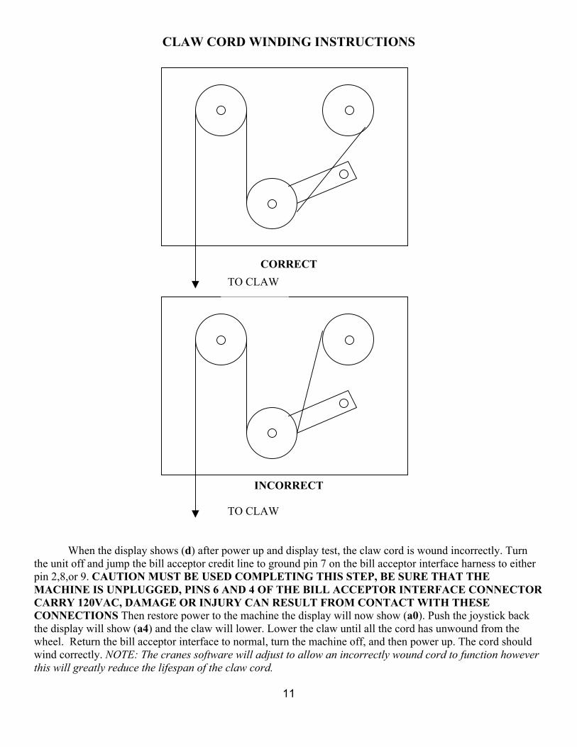
CLAW CORD WINDING INSTRUCTIONS
CORRECT
INCORRECT
TO CLAW
TO CLAW
When the display shows (d) after power up and display test, the claw cord is wound incorrectly. Turn
the unit off and jump the bill acceptor credit line to ground pin 7 on the bill acceptor interface harness to either pin 2,8,or 9. CAUTION MUST BE USED COMPLETING THIS STEP, BE SURE THAT THE MACHINE IS UNPLUGGED, PINS 6 AND 4 OF THE BILL ACCEPTOR INTERFACE CONNECTOR CARRY 120VAC, DAMAGE OR INJURY CAN RESULT FROM CONTACT WITH THESE CONNECTIONS Then restore power to the machine the display will now show (a0). Push the joystick back the display will show (a4) and the claw will lower. Lower the claw until all the cord has unwound from the wheel. Return the bill acceptor interface to normal, turn the machine off, and then power up. The cord should wind correctly. NOTE: The cranes software will adjust to allow an incorrectly wound cord to function however this will greatly reduce the lifespan of the claw cord.
11
TOY SOLDIER CRANE TROUBLE SHOOTING
1. Upon receipt of your crane all packing materials should be carefully removed. Care should be taken to ensure that ALL ties securing the claw and gantry are removed BEFORE operation is attempted. The unit should be placed on a smooth level surface and the wheel locks engaged to prevent accidental movement or “tilting” during game play.
2. This unit is designed FOR INDOOR USE ONLY exposure to the elements will cause premature failure.
3. Any repairs or maintenance that you Toy Soldier may require should only be carried out by FULLY QUALIFIED PERSONNEL failing to do so may result in unnecessary damage to the machine or injury. Please feel free to contact Coastal Amusements with any concerns that you may have. We may be contacted at:
4. Caution should be taken to observe power supply polarity when repairing this machine, damage to components can occur from improper connections. Precautions should be taken when handling integrated circuits (chips) to avoid static discharge; machine should always be powered off before changing any components.
5. Coin Comparator will not accept coins/tokens.- If coins cannot be inserted into slot check slot for debris or damage. Check that a comparison coin has been inserted in the correct slot in the coin comparator. Ensure that coin comparator is compatible with coin/ tokens being used.
6. Coins/ Tokens are returned after insertion or no credit is given after coin insertion.
a. Check that coins/tokens are not malformed or damaged. b. Check that wiring harness is correctly connected to coin comparator. c. Check that “comparison” coin is of correct type and that it is inserted correctly (not cocked) in slot. d. Check that comparator model is compatible with coins/tokens being used
7. No credit after coin/token insertion-
a. Ensure that coin path is clear and aligned from coin comparator to cash box. b. Check that J8 is connected properly to main logic board.
a. Cord is improperly wound. Hold “stop- down” switch located on gantry (Item 28 Gantry & Assembly II), cycle power taking care that hands and fingers are not in a position to be pinched or otherwise injured, the cord should wind correctly.
b. Check that claw cord is not “out of track” if it is, hand wind cord correctly (see cord winding instructions pg. 12 of manual) normal operation should be restored. Note: Front and Top gantry covers must be unscrewed and removed in order to access claw cord.
c. Activation of “tilt” due to excess shaking play can cause this error code to appear.
9. If display shows C0 blinking-
a. Coin comparator switch is in wrong (normally closed) position; restoring switch to normally open and cycling power should restore normal operation.
b. Attempts to “fool” the coin comparator can also cause the display to blink C0. A shorted or blocked coin comparator can also cause this condition.
10. Gantry does not “home” properly-
a. Cycling power should restore normal operation, If it does not then check back or front depending on home position and left stop switches (Gantry &Assembly I items #23, #22 and #21 respectively).
b. The main logic board has developed a fault.
11. Gantry does not move front or back with joystick operation-
a. Ensure that the front back switches of the joystick are connected and operating properly. b. Check that J1 is properly connected to main logic board. c. Check front and back stop switches (Gantry assembly I #’s 22 & 23 respectively) for correct operation
and harness connection. d. Check front/back motor for proper operation and correct connection to harness. e. Check front/back fuse. f. Ensure that shaft pinion (Gantry assembly I # 13) is properly positioned. g. Check that J4 is properly connected to main logic board and that no pins are damaged or missing. h. Check all connections along gantry harness.
12. Gantry does not move left or right-
a. Ensure that the left right switches of the joystick are connected and operating properly. b. Check that J1 is properly connected to main logic board. c. Check that left stop switch is connected and operating properly. d. Check left/right motor for proper operation and correct connection to harness. e. Check left/right fuse. f. Ensure that shaft pinion (Gantry assembly II # 24) is properly positioned. g. Check that J4 is properly connected to main logic board and that no pins are damaged or missing. h. Check all connections along gantry harness.
13. Claw does not descend upon pushing “drop” button, only when game times out-
a. Check “drop” button for proper operation and connection to harness. b. Check that J1 is properly connected to main logic board.
13
14. Claw does not drop down at all-
a. Check up/down motor for proper operation and correct connection to harness. b. Check up/ down fuse. c. Ensure that shaft pinion (Gantry assembly II # 19) is properly positioned. d. Check that J4 is properly connected to main logic board and that no pins are damaged or missing.
15. Claw does not drop or does not travel a to game floor before stopping-
a. Check for stuck, knotted, or otherwise obstructed claw cord. b. Check stop up (Gantry assembly II # 29) switch for proper function and connections. * Stop up switch is
normally closed as opposed to the other stop switches. c. Ensure that claw cord is of proper length.
16. Claw does not release prizes upon returning to “home” position-
a. Depending on home position check either front or back and left stop switch for proper function and connection. (Gantry &Assembly I items #23, #22 and #21 respectively)
b. Check that J4 is properly connected to main logic board and that no pins are damaged or missing.
17. Claw does not return to up position, gantry moves to “home” position.
a. Check stop down switch for proper operation and connections.
18. Claw does not return to up position, no gantry movement-
a. Check up down motor for proper function and connections. b. Check up/ down fuse. c. Ensure that shaft pinion (Gantry assembly II # 19) is properly positioned.
19. Claw does not close, gantry returns to home position-
a. Check 48V on power supply. b. Check claw fuse. c. Check coil continuity and connections. d. Ensure VR1 &VR2 are set correctly.
14
GANTRY ASSEMBLY DRAWINGS I ITEM # DESCRIPTION COASTAL PART # WU-MAR PART # 1,3,18,20 Front/Back Wheel PE-WHL-FB-002 S002